ie e.' - apps.dtic.mil
TRANSCRIPT

--R66 545 STRUCTURRL INELASTICITY (28TH) A FINITE ELENENT /'VECTORIZATION' METHOD FO..(U) MINNESOTA UNIVMINNEAPOLIS DEPT OF AEROSPACE ENGINEERING AND M.
UNCLASSIFIEDP G HODGE FEB 86 REM 142 4 N88814-82-K-U20 F/G 2911/LiIIlEEllEEliI
IIflI.ll
IE E.'

2 .
mwRn~p REOUTO IF'25I""R
%=

Report AE-H2-4
ISTRUCTURAL INELASTICITY XXVIII
q• .Ln
p
Final Report on A Finite Element "Vectorization"co Method for the Solution of Crack Growth Problems(0 in two or three Dimensions
Philip G. Hodge, Jr., Professor of Mechanics
.
Department of Aerospace Engineering and MechanicsUniversity of Minneosta
Minneapolis, Minnesota 55455
February, 1986
Final Report
Prepared for
OFFICE OF NAVAL RESEARCH
CD Arlington, VA 22217
~APR 1 i8OFFICE OF NAVAL RESEARCH "Chicago Branch Office536 South Clark St.
I..' Chicago, IL 60605
dkm- I862 1 @34
%-

SaICUMIT CLASSIFICATION OF THIS5 PA4E MW9v Due& Enteo..V _________________
REOTDCMNAINPAGE READ INSTRUCTIONSREPOT CCU~ETATONBEFORE C0~dPLEThG FORMICrW REPORT11 WUBE L RECIPIENT'S CATALOG siumiSef
AEM-H2-4 54. TIL9(md~ubdfeS. Tyra OF 4REPORT a pEr4OO COVERED
Technical ReportFinal Report . ~ OG EOTNME
AurNORS. CONTRACT 0R GAAT NUMUeR(.e)
Philip G. Hodge, Jr., Prof. of Mechanics N01-2K02
8. 09ERFORMINO ORGANIZATION NMA ANDORS 0119111. PROGRAM E1L9iiEN7T PROJECT. TA39
University of MinnesotaAn.9AvoiWHT"hssMinneapolis, Minnesota 55455 NF 064-429
11. CONTROLLING OFFICE MNZ AND ADDRUS IS. REPORT DATE
OFFICE OF NAVAL RESEARCH Ferur 1986 O P~
Arlington, VA 22217 32 UM6 f A4
14- MONITORIN13 AGENCY NAME A ADDIRESS(It difloeftn how Ca,4a.Jiln Offoe) I&. SECURITY CLASS. (.of .5
OFFICE OF NAVAL RESEARCH UnclassifiedChicago Branch Office &DSSIAOWOGRIN536 South Clark St. k'uChica o. IL 60605
16 IITRIUTION STATEMENT (a# Wei Ropet
17. OISTRIDUTION STATEMNT (of a,* abeirpi nodm In &1"&* 20. It I11foenE ban *0APO
IS. SUPPLEMENTARY MOTES
Plasticity, Crack propagation, Finite-element method.
20. ABSTRACT (C.ando. M ,1,o#8 of4 #1110"000 and IWmaaf Oph by oo M i)
* -A summary and bibliography are presented of the investigations of
structural inelasticity.which were carried out at the University ofMinnesota under the sponsorship of. the Office of Naval Research during
6the period 198 1-1985. Also included is- a, report on an investigation .completed after expiration of the contract. W*-
DD 1473 EDITION OP I NOV 651 IOSOLTE
SN 10*0I*,*IsEcumRTy CLMIIPICATiON OF THIS PAGE (Who Onto 8#*

.:
DISCLAIMER NOTICE
THIS DOCUMENT IS BEST QUALITYPRACTICABLE. THE COPY FURNISHEDTO DTIC CONTAINED A SIGNIFICANTNUMBER OF PAGES WHICH DO NOTREPRODUCE LEGIBLY.
'C
-a,.
5
V
'--a

FINAL REPORT
iiesearch conducted under this contract Included two distinct
projects. The first was concerned with using simple truss models to
illustrate certain critical aspects of nonlinear material behavior Results
obtained were Issued In two reports listed as Items I and In the
bibliography on page 2. This project was carried out by the Principal
Investigator, Philip G. Hodge, Jr.
The other project was concerned with using a constant-strain finite
element method to find complete solutions for the stress and
displacement in a plate with a centered crack .This research was carried
out by James Malone, Research Assistant,* under th' joint direction of the
Principal Investigator and of Professor Robert Plunkett.AlThe elastic
solution was obtained first*,t was presented in the report listed as item
* 3 in the bibliography. 1he elastic/plastic solution was completed after the
expiration of this contract. A description of this phase constitutes the
main body of this Final Report; it is planned to submit the material for
publication.
Now Dr. James Malone, Research Engineer, GeneralMotors Laboratory, Warren, Michigan.
S

FILIAL opT p 2
Acces!7ion For
NTITSC &
Dist, ,, :/
Avnil-' - BIBLIOGRAPHY
Dist Si -
Report AEM-H-2-1Philip G. Hodge, Jr.SIMPLE EXAMPLES OF COMPLEX PHENOMENA IN PLASTICITYa"Mechanics of Material Behavior, R. T. Shield & G. Dvorak,
* eds., Elsevier Scl. Publ. Co., Amsterdam, 1984,pp 147-173.
Report AEM-H2-2Philip G. Hodge, Jr.SIMPLE EXAMPLES OF NON-LINEAR TRUSS BEHAVIORInternational Jomnal of Solids and Structre 20,1001-1008 (1984).
Report AEM-H2-3James 6. Malone, Philip 6. Hodge, Jr., aid Robert PlunkettFINITE ELEMENT MESH FOR A COMPLETE SOLUTION OF APROBLEM WITH A SINGULARITYJoral of Computers and Structres (in press)
L ' -." ~.-~- * .

M FINAL IEPMT FskvwV 4. ItM pop
A.
AN ELASTIC -PLASTIC FINITE ELEMENT
SOLUTION FOR A CRACKED PLATE
byPhilip G. Hodge, Jr., James G. ralone, Robert Plunkett
ABSTRACT
In this paper, the finite element method is applied to a center-cracked platesubject to opening mode tensile loading. A complete elastic-plastic plane-stresssolution for strain hardening materials obeying a von Ilises yield condition andPrandtl-Reuss stress-strain relations is obtained using only constant strain elements.An accurate representation of the stress-strain field, even at distances veru close tothe crack tip, is achieved by the use of a mesh arrangement in which the size of theelements decreases In a geometric series as the crack tip Is approached. Thenumerical solution is compared with and used to discuss the range of validity of thewell known HRR (Hutchinson-Rice-Rosengren) crack tip solUton valid for small scaleielding. The influence of different amounts of hardening and the effect of changes inIhe mesh arrangements are also considered. Features orthe finite element algorithm
which reduce tte total computing time are discussed. The finite element program isexecuted on the Cray-I computer and the effect or vectorization on computationalspeed is discussed for this problem.
1. INTRODUCTION.
In a recent paper [11 we have shown, for the particular problem of acenter-cracked elastic plate under tensile loading, that a finite element formulationwhich uses oni constant-strain elements can provide an accurate representation ofthe stress-strafn field even In the neighborhood of the stress and strain singularitlesat the crack-tip. This was achieved Dy using a large ruimber of triangula elementsarranged In a mesh In which the size or the e ements decreases in a geometric seriesas the crack tip is approached. The present paper extends this technique to handlenonlinear material iihavior and discusses te resulting complete elastic-plasticsolution for crack problems.
Miethods commonly used in nonlinear finite element analysis are discussed byBathe 12 and Zierklewlcz [3); practical procedures for varlots applications have beenpresented by Bathe and Cimento [41 and also by Bergan et al 15]. In an elastic-plasticUnite element analysis, the most effective wag of dealing with the materialnonlinearity is by an incremental approach in which he load is apied in a number ofsmall Increments. Within each increment. the true stress-strain relations areapproximated and an Iterative process is applied to ensure that the equilibrium
equations are satisfied to within some specified level of accuracy. At each iterativestep tVe solution of a banded system of linear algebraic equations Is required whichaccounts for a large portion of the computational cost. For a given f Inite elementmesh, the aocuracy of the solution can ie improved by reducing the size of the loadIraements and/or Imposing a tighter convergoence criterion. However, this may causea substantial increase in tlie total computing time so that in practice a balance has to
.4. be struck between accuracy and computational cost.

M FOW UAL 3T Fiekua, 4. W2S "P 4
Access to a CRAY-I supercomputer has made it feasible for us to consider a- - technique for nonlinear finite element analysis which uses a large number of unknowns
and ma small load Increments. This is possible because the computational speed andmemory capacity of this machine are much reater than revous. generations ofcomputers. For example, rates of 69 MFLOPS million floating point operations persocond) hav been recorded [6.71 on the CRAY-I Sfor the solution of dense sstems oflinear equations of order 300 usirgLLU decomposition with pivoting ( without resortingto the use or assembly langu ).This is about 28 times faster tan the 1&113033 and800 tImes faster then thd V ; I In8o. Rates in excess o 140 MFLOPS have beenachieved by the use of assembly language [81.
In this paper, we consider the particular problem of a center-cracked plate subjectto mode-I (tensile opening mode) loading. Small strains and displacements areassumed. This means that material nonlinearities but not geometric nonlinearities areconsidered. This problem has been the subject of considerable interest. In thefollowing we will mention only some of the many analitic and numerical paws whichhave aieared In the literature. A more detail accbunt is contained In the reviewarticle by Rice [91.
The asymptotic form of the plastic crack tip stress-strain field in plane strain andplane stress has been established analytically by Rice [101. Rice and R.s. en [1 I].and Hutchinson [12, 131 for strain hatdening and perfectly plastic materials. Thissolution, frequently referred to as the HRR solution, is based on the deformation theoryof plasticity and is valid under conditions of small scale yielding [141. It will bIdiscussed In more detail later in this paper.
For power law hardening materials, Tracey [151 used the finite element method todetermine the plane-strain stress state at the tip of a crack under conditions of smallscale yielding. He used special singu laritU elements at the crack tip in which thedisplacement shape functions were chosen to represent the form of the HAR solution;elsewhere 4-nodeid isoparametric elements were used. Hilton and Hutchinson [161,carried out a plane-stress finite element analysis for both small and large scaleplastic yielding. Their method used constant strain triangular elements together witha special singular element surrounding the crack tip in which the HRR solution wasembedded.
We have recently shown [1], for an elastic analysis, that constant strain elements-.can. be use to obtain an ac rate representation of the stress-strain field in the
region near the crack tip. For the elatic-plastic analysis, our. approach has also beento use a large number of comstant strain triangular elements and a mesh which issimilar to tat Iused in the elastic finite element analysis 111. Our nonlinear finiteelement procedure yields a complete elastic-plastic solution at a reasonablecomputational cost wh executed on the CRAY-1. We demonstrate that on a scale inwhich the crack length eqals one it is possible to obtain a sufficiently accuratesolution for the stress field at distances as close as 10 -0 from the crack tip. Thissolution is used to discuss both the spatial range over which the HRR solution holdsand the level of applied load at which the HRR solution no ionger accurately representsthe crack tip stress-strain field. Our solution provides a good representation of thestress-strain field at all levels of applied load.
In section 2, we describe the element mesh and the algorithm which Implementsour elastic-plastic finite element analysis. The numericat results are discussed inSection 3. The effect of different element meshes on the computed solution and the

a mAL IEPC Fdnbuuy 4. ING pop
Influence of hardening are also reported in that sectIon. In Sect ion 4. computing times
for different meshes and for different amounts of hardening are discussed. Featuresof the algorithm including vectorization which reduce the computational cost are alsodescribed. Finally. some conclusions are presented in Section 5.
2. METHOD OF SOLUTION.
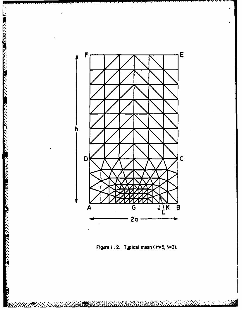
In this paper the particular problem of a reC taMlar plate containing a centrallulocated ct to mode-iopening mode) Ioding is considered. The cracklength is 2a anda the pate is of height 2h and width 4a (see Fig. 1). The boundaryconlitions along the top and bottom edges are uniform displacements In the verticaldirection and zero traction components in the horizontal direction. Zero tractions areprescribed on the remaining edges of the plate and along the crack faces SG. By theusual summetru argument, the problem can be reduced to that of solving for onequadranf ABEF Csha-ed area) of the plate with boundary conditions as shown in Fig. 1.
-,= (a) Finite element mesh.
usesThe finite element program is based on the well known displacement method andUses only co tant strain elements. The rectangular domain ABEF.(Fig. 1) is
iscr..etize into tri .ular elements by a mesh generating program which has beendeveloped so that different mesh arrangements can be automatically produced. Atypical mesh arrangement using 216 eFements is shown in Fig. 2. Meshes rangin insize from 564 to 2064 elements and having elements as small as 10 - a at thecrack tip have been used in this study.
The mesh over portion ABCO of the plate is formed from the quadrilaterals definedby a set of rectangular rings intersected by rays. Let M numbers rt be defined by
rn:a, r==oM-1 , I-1,M-2,....2.1 (2. 1)
where = is a constant. The rings are a set of nested r x 2r rectangles with lowercorners along .AGB (see Fig. 2) at distances ±t r, from ihe crack tip G. Let N-Ierioista points be inserted along BC and the same spacing contirnie along CD andD1 DA. The rags are straight lines from 6 through these points. The innermost ring isdivided Into 4N equal scosceles triangles ad the quadrilaterals in the remainingrings are each spli into two triangles b! their i sagnals as shown In Fig. 2. Finally
athe mesh 1 t by filli ng the remainino portion DCEF with approximatelu squarerectangles of constant size which are split into triangles. The mesh shown in tg. 2 isfor M=5 and W-3.
The aspect ratio F of a generic triangle JKL in ring i+l along GB is given by
F = IJKI/IJLI = (r,, - r,)/(rN) = N [1/ac-I (2.2)Hence the geometric coefficient oc in Eq (2.2) is related to a typical aspect ratio by
o: = (I F/N)- 1 (2.3)
We have found that good results are obtained by taking F:1.
A similar mesh has been used [11 in an elastic study of an Infinite plate containipga centrally located crack. The main features of this mesh arrangement are more fully

OWEIFW. AL WT FWbruuy 4, VW iup C
discussed In Ref. [ I].
(b) Material properties.
The plate material Is assumed to be ho nea.s and initially isotropic, obegingHooke's law In the elastic range with initial yielding determined bD the Von Mlsesyield conditior After Vielding, plastic strain increments are defined an associatedlow rule with linear Iardening. Isotropic growth of the uleld condit oan Is assumed.
At any point where unloading occurs the incremental form of Hooke's law will againappi. These assumptions lead to the well known Prandtl-Reuss stress-strainrel aions in the incremental theory of plasticity. The solution presented in this paperis for a state of plane-stress. It is a so assumed that both strains and rotations aresmall. The validity of these assumptions will be discussed in Section 3.
The elastic-plastic stress-strain matrix D(o) which relates changes in stress tochan in strain at points of the material which have ielded and are loading has beenderived under the above assumptions by Yamada et al [I71. During anuj time incrementAt the stress increments AO and strain increments At are related
A0 = D(ol) &e (2. 4)
where A = [AO Y At IT A [AE E AV ,T and V is theengineering shear comporent of Wrain. If the m'teriaPis elast%, Do) is t~constantmatrix
D() : ,E/(I-_2) U 1 0 (2.5)0 0 (1 ,-u)/2j
whether or not earlier plastic behavior has taken place. If it is plastic,or 0, + 2P
D(d)= De, m (E/Q) / - * o 12up
.- [ u(2. 6)--0 ,,'O.+2oP -Ir ( ,, 1
'1ii2 ( +v -" ( +U )/(l O J: where a"Is the deviatoric stress and U' is the equivalent stress.
.. 3: [(3/2) (Wi &'i& ) 1/2
P (2H/E) U2T'2 /(I V)
,.-.....~~~~~~~~~~~.....-.... ........... ..... .. .: ,........,...;.-....-....,.:' , '

R FUS ALEPORT F minuy 4. iN pop 7
Q a R 2(1-0 2)P (2.7)
R 2 m +20O s a y'2
H EET /(E- ET)
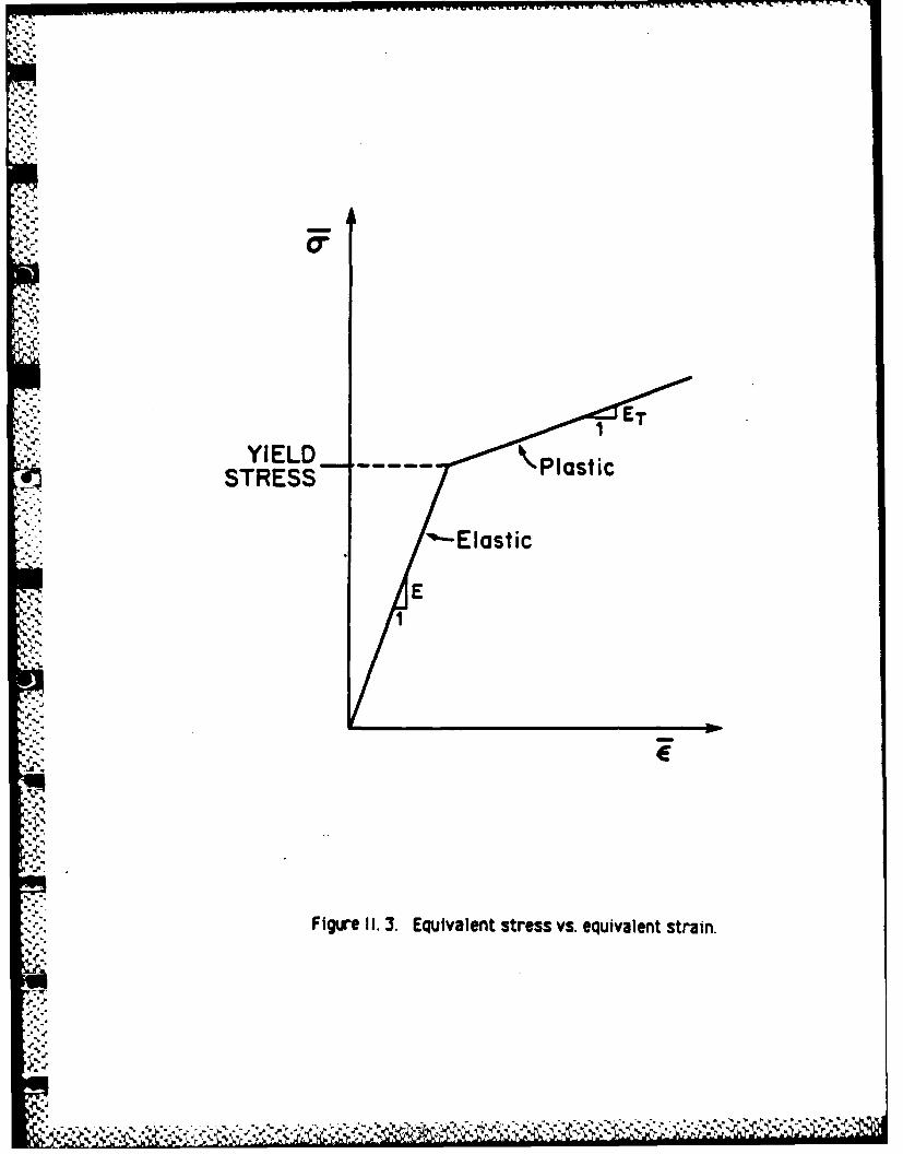
where a is the Poisson's ratio, E is Young's Modulus, and ET Is the plastic modulus.A plot of equivalent stress U versus equivalent strain r' for a material
satisfqing our constitutive assumptions is shown in Fig. 3. The equivalent strain !-is
- = [(3/2XE'ij eij) 2 (2.8)where E'i are the deviatoric components of strain. in practice a piecewise linearstress-strain law can be determined from data obtained I a simple tension test for areal material. We have chosen the most simple case, i.e. a bilinear stress-strain law,but the above discission can be modified in an obvious manner to handle any piecewiselinear curve.
(c) Nonlinear finite element analysis.
Since the strain is constant in each element, the column matrix of element strainse and the column matrix of nodal displacements u are related by
e=B u (2.9)
. where the constant matrix B depends only on geometry and not on material behavior.
The nodal force matrix F and the stress matrix o are related by the similarrelation
.F :A c (2. 10)
where A also depends onl on eometry. Equations (2. 9) and (2. 10) must be valid foreither total or Incremental behavior.
During ay incremental time step At. the stress and strain increments are related
JCY.fe+AE (o) De =(cf) AE (2. 11)where o* Is some mean value of the stress state durin the strain interval Ae.
.. Combining Eqs, (2. 4), (2. 9), and (2. 10) we obtain Rhe usual matrix equation
K(O)Au = AF (2. 12)iwhere the "stiffness' matrix K is given by
K (a) = A D(O) 8 (2. 13)
Due to the incremental nature of the stress-strain relations (see Eq. (2. 11)), thisproblem is best solved by an Incremental procedure in which the load is applied in a

0m FNAL EPORT Febrway 4, 1"6 1e.
series or Increments AF",. Thus the load at the end of Increment M isIM =Fm- +*AFn Ml19l2,..q (2. 14)
where FO . F. are the initial and final loads respectively.
The problem can be psel s follows: Given a complete slution u efl,~heco~et I) stepg to ofthe~ sptep correspondi
the external load F.By I~ 4ite 'aolution . we mean column matrices for noal
duilcngt.' tQodal focs element strains, and element stresses. The processduring the M M step is to obtain incremental changes Au A d idisplacements, strains, and stresses. respectively. correkspondin~to hmrken inload AF, which satisfy Eqs. (2. 9) to (2. 11), i.e.
Ae mBAU m (2. 15)Aam ~am e m(2. 16)
Fm zAc (2. 17)
where 0 a + Aa agdo a is some mean value of the stress state during thestrain inervaiA , ("a;,~ will be defined later).
The first step is fully elastic and the solution is obtained by direct solution of theelastic finite element equations. For each later step an iterative method is used tosolve the kinematic, constit tive, and equilibrium equations (2. 15, -16, -17) at stepM. The first estimate Au m "Is given by
where At;,.. is tItff change in jpplacement which occurred during the previous (M- 1)~step. NetAE ,.and Aoa" are obta" in order from Eqs. (2. 15) and (2. l*usi r, a thei initial (meanstress cr, ; the first total stress estimate crt
iso iWby add Ing Aam t the initial value 0l,-..~
In general a (1) will not satisfy equilibrium. We begin the iterative process bydefining a residu 1 force:
Pm(l) = Fm, -Aorm~1 (2. 19)
* and obtain a correction to the displacement increment f ield by solving
Km Sum(i): =pM(l (2. 20)
where
Km 2A D(Ym-) 8(2.21)
KM is factored (CholeskV algorithm) in the first iteration. This factored form isMerter retained for the current step so that only a back suistltlon need beperformed Ive (2. 20) for each sJWeedIinIteration. Then Au is obtained bMj
q adding SC to A l)adA " s obtainied from (2. 15). A'lean stress am,adding Su. m to Aum ad e
M! FMU NiT Fehry 4. 196 pep 9
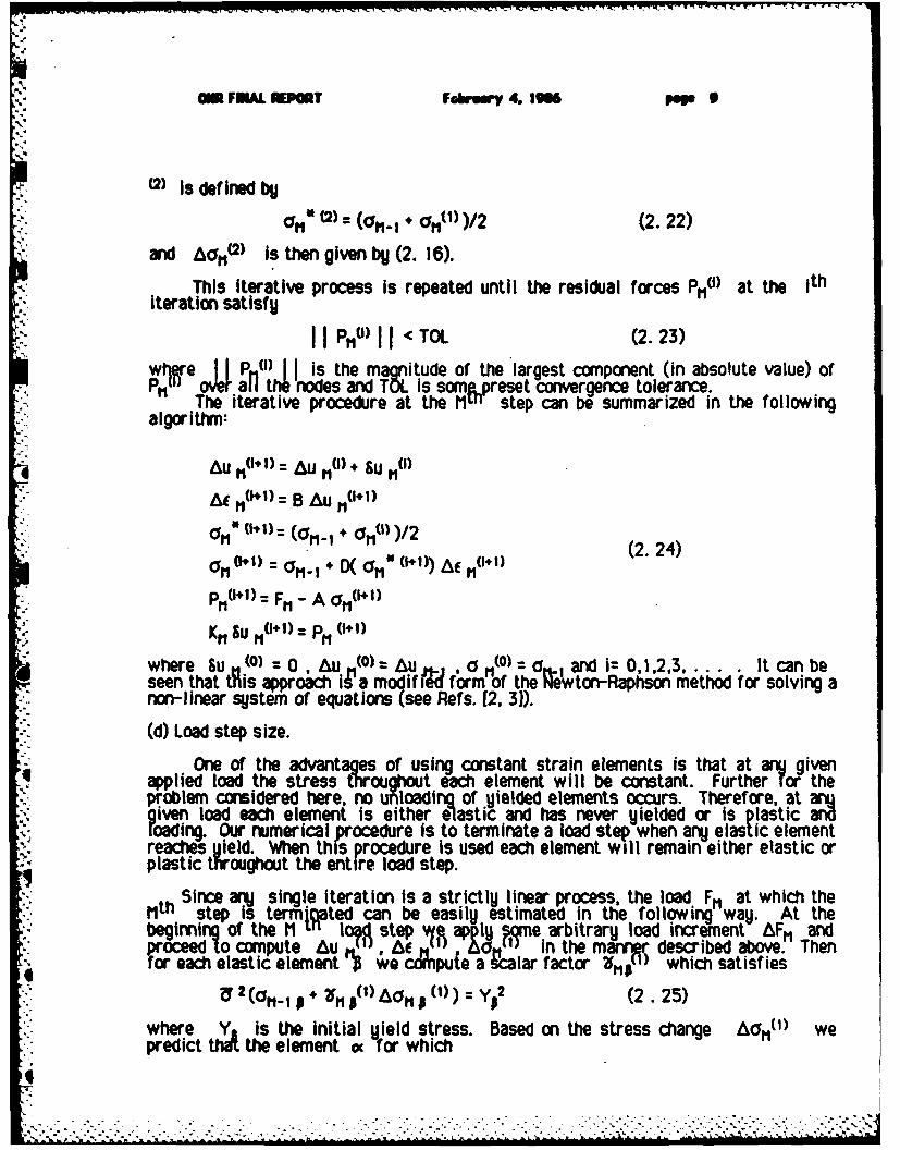
(2) Is deflinedb
":" (2) :(=1 '. + o,())/2 (2.22)and AO.0 is then given by (2. 16).
This iterative process is repeated until the residual forces Pmu) at the ithiteration satisfy
P,11 )I < TOL (2.23)wjjre is the magnitude of the largest component (in absolute value) of-PM, oJer all te nodes and TOL Is somep.jreset convergence tolerance.
The iterative procedure at the Mu step can be summarized in the following•"algorithm:
Au MO+ 1): Au MO) + Lu M(i)
At M(+1) : B AU MO1+ 1)
a 0+ 1) r(I1I) ( a 0+0 1Am)2 (2. 24)-01o (I) * . IX o," (141)) & 11(14)
p1 (t+ 1) = Fm - A O(r11 11
KM Su M + 1) p 0( 11
where Su (0 - 0, Au(O) = Au .,, () o and i= 0,1,2,3..... It can beseen that tAis approach iN'a modif d form of the Nnon-linear system of equations (see Refs. [2, 3)).
(d) Load step size.
One of the advantages of using constant strain elements is that at an givenapplied load the stress throughout ech element will be constant. Further for theprotem consldered here, no unloading of Ulelded elements occurs. Therefore, at arggiven load each element is either elastic and has never yielded or is plastic anroading. Our numerical procedure is to terminate a load step when anij elastic elementreaches yield. When this procedure is used each element will remain either elastic orplastic throughout the entire load step.
Since arvj single iteration Is a strictly linear process, the load F. at which theMth step is termiated can be easily estimated in the following way. At thebegiming of the M U I lo step 9e app i 'e arbitrary load increment AF1 andproceed to compute Au A ,d in the marvnr described above. Thenfor each elastic element " A e ccnpuie a alar factor p which satisfies
U 2 (O i. 0 + 2FM )o 1 8 )) 0) y 2 (2.25)
where Y is the initial yield stress. Based on the stress change A011O) wepredict thA the element o for which
,:,: :.:.:- .:::.: -::-,... . ...... :....,....... ._........ .,....... . ....... -. ,,,',:

MU FLIMPORT Few. 4. IM pep. 1S
",.(') z min$( In;1)) (2.20)
will be the element most likely to first reach yield dunrh the frrent load step. Theentire Incremental solution can now be scaled QO the fact 2rr l e
A0TMO ) -(i)n WAO() (2.27)
so that element oc will have just reached yield when the load is Incremented by anamount
A = 16 ) AF (2.28)At each Iteration, improved estimates of the load Increment AF requiredelement oc just reach Vield can be obtained by compling scalin factors 2( felement cc correspondig to the stress change Ad"- using Eq. 2. 25).
It was found that computin scal ing factors for only the first three iterations ineach load step was the most eflicient procedure. The load increment AiF Is then heldfixed for the remaining Iterations of the load step. At the end of the load s'4ep, the yieldcondition may not be satisfied exactly by element a but this Is taken care or bij theuse of a smeared yield condition.
The idea of a smeared yield condition is based on a technique used by Yamada et al[171 and, in a different context, by Hodge and Van Rij [18. 19 to substatially reducethe total number of load steps. At the end of each load step, arj elastic elementfor which the equivalent stress U satisfies
0.99 YO < U' <1.02 Yj (2. 29)
has its yield stress Y, redefined so that Y, = 3 .
This means that elements which have not yet reached yield but which are closeenough to satisfy (2. 29) can be treated as plastic in the next step. This avoids theneed for one or more additional steps to bring these elements to yield. It also meansthat the solution at the end of the step can be accepted even if some elements exceedthe yield stress, provided (2. 29) is satisf led. The alternative would be to repeat theload step using an improved estimate for the Initial size of the load increment.
The main features of the program have been described above. A more detaileddescription of the program algorithm may be found in Ref (201 which contains theprogram documentation and Fortran co e.
3. RESULTS AND DISCUSSION.In this section an assessment of the accuracu of the solution particularly in the
region close to the crack tip will be given. The effect of different mesh arrangementson the solution will also be discussed. Comparisons will be made Detweenelastic-plastic solutions .correspoling to different amounts of h. dening and alsowith the purely elastic solution. The numerical elastic-plastic solution in the regionsurrounding thi crack tip will be compared with an analytic solution which is validunder conditions of small scale yielding In which the plastic zone is small compared tothe plate dimensions.
p.
Mr FWL. INEMI Feb=., e4. Is p II
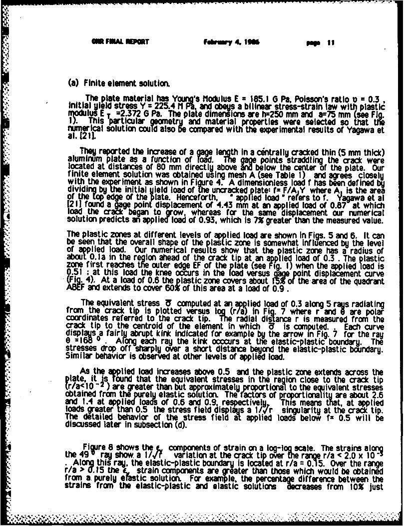
(a) Finite element solution.
The plate material has Young's Modulus E - 185.1 0 Pa, Potsson's ratio v = 0.3,Initial yield stress Y =_225.4 M P, and obeys a billnear stress-strain law with plasticMvodulusE T =2.372 6 Pa. The plate dimensions are h=250 mm and a=75 mm (see Fig.I). Ths particular goometru and material properties were selected so that thenumerical solution could also 5e compared with the experimental results of Yagawa atal. [21.
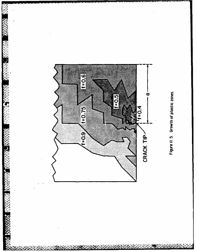
They reported the increase of a gage length in a centrall U cracked thin (5 mm thick)aluminum plate as a function ofol..The game points straddling the crack werelocated at distances of 80 mm directly above W below the center of the plate. Ourfinite element solution was obtained using mesh A (see Table 1) and acres closelywith the experiment as shown in Figure 4. A dimensionless load f has been defined Ndividing bUThe initial yield load of the uncracked plate: f- F/A Y where A is the areaof the top edge of the Pilate. Henceforth, *apidld re~ers to f. _agawa ta
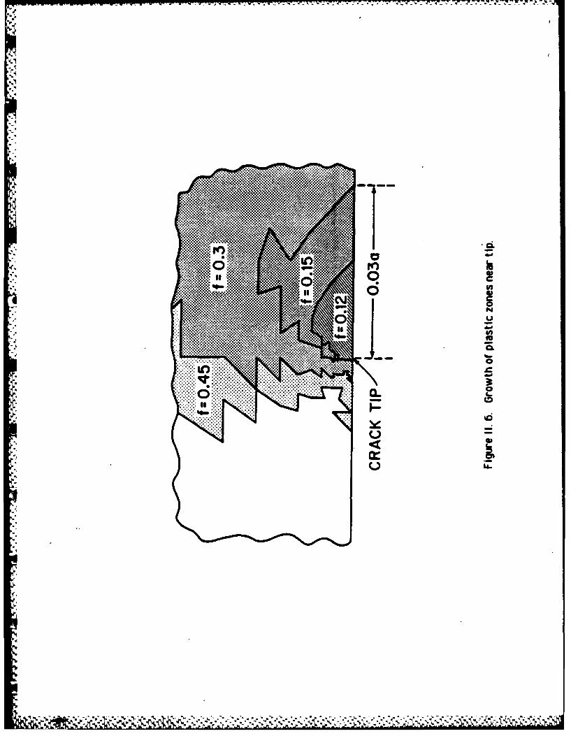
Spoint displacement of mm at an applied load of 0.87 at whichload the cratc began to grow, whereas for the same displacement our numerical* solution predicts an applied load of 0.93, which is 7% greater than the measured value.The plastic zones at different leves of lied load are shown in Figs. 5 and 6. It canbe seen that the overall shape of the pItic zone is somewhat influenced by the levelof applied load. Our numerical results show that the plastic zone has a radius ofabout O.la in the region ahead of the crack tip at an applied load of 0.3. The plasticzone first reaches tho uter edge EF of the plate (see Fig. 1) when the applied load is0.51 ; at this load the knee occurs in the load versus ant curve(Fig. 4). At a load of 0.6 the plastic zone covers about 15 or the area of the quadrantABEF and extends to cover 60% of this area at a load of 0.9.
The equivalent stress U computed at an applied load of 0.3 along 5 rays radiatingfrom the crack tip is plotted versus oIog ( n Fig. 7 where r and 0 are polarcoordinates referred to the crack tip. Te radial distance r is measured from thecrack tip to the centroid of the element in which U is computed. . Each curvedisplays a fairly abrupt kir* Indicated for example N the arrow in Fig. 7 for the ray0 :168 .. ARong each ray the kink ocurs at the elastic-plastic boundary. Thestresses drop off sharply over a short distance beyond the elastic-plastic bDoUndary.Similar behavior is observed at other levels of applied load.
As the applied load Increases above 0.5 and the plastic zone extends across theplate, It is tound that the equivalent stresses in the region close to the crack tip(r/a<10- ) are greater than but approximately proportionali to the equivalent stressesobtained from the prelu elastic solution. The factors of proportionality are about 2.6and 1.4 at applie Ioa of 0.6 and 0.9, respectively This means that, at appliedloads greater than 0.5 the stress field displays a lI/r singularity at the crack tip.The detailed behavior of the stress field al applied loads below f= 0.5 will bediscussed later in subsection (d).
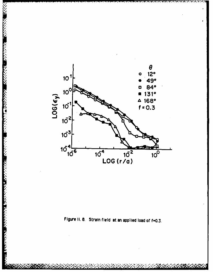
Figure 8 shows the C components of strain on a log-log scale. The strains alongthe 49u ra show, a I/./f variation at the crack tip over the range r/a< 2.0 x 10Along this rag, the elastic-plastlc boundary is located at r/a : 0.15. Over the ranger/a > C.15 the e, strain components are greater than those which would be obtained
from a. purely elastic solution. For example, the p centage difference between thestrains from the elastic-plastic and elastic solutions decreases from 10% just
• ," ,%.,. ' ,,', '. '. .',. ..',. ,,','.,. .,',, ..','-'..',/ ..'... -, .'... -''.' . ,.. ... ....... ... .- ."..... . . ..-.. .-.- -.. . . ...- .-. .. ,-.

PIC GI1E F ,OINAL T Fsbrpy 4. 906 pop 12
outside the elastic-plastic boundary to less than 3% near the edge of the plate (for r/a> 0.9). As the lplied load Is increased the distance from the crack tip over whichdisplas a I/v/r variation increases in extent up to a maximum distance of about
r/a .02 along the 49 v r.a at an applied load or 0.9. The behaviour of the strainalong other raus Is qua litativelu similar; the largest ey, strain components Occurai- the raifr which 9=81'
We have also considered a material with a higher amount of hardening ( E -18.51 6 Pa ). The behavior of the stress-strain field for this materiar is
alitativelg similar to that obtained for the lower hardening material (E T = 2.372 Ga) which has been discussed above.
(b) Effect of different mesh arrangements.
The presence of a singularity in the stress-strain field at the crack tip requiresthat the arrangement of 1lements in the mesh must be carefully selected if anaccurate solution is to be achieved at a reasonable computational cost. The elasticfinite element solution for a crack problem, using a mesh similar to that described inSec. 2 is discussed in Ref. [I11. it was found thatncreasi the number of rings In the
S-' mesh produced more accurate results in the region close to the crack tip, whereas anincrease in the number of rays gave more accuracy over the rest of the plate. It wasalso shown that for a given mesh, increasing the rumber of rings while holding thenumber of rays fixed ( thereby increasing the density of elements only at the crack tip) produced less than 0. 1% improvement In the accurac of the solution over the range r>lOOr where rl is the position of the irmermost ring in the original mesh. We nowshow that similar observations hold for the elastic-plastic problem.
Four specific mesh arrangements have been considered (Table 1). Solutions for thehigl-hardenin material CE 18.51 . Pa )were obtained for each mesh over a range ofloads up to 0.. At this 1ad the plastic zone extended to touch almost all of the edgeEF (see Fig. 2). To facilitate a comparison with the results of Ref. [II], we w 1Icompare the vertical components of displacement v at nodes along the crack faceobtained from each mesh. Similar behavior is observed for v atong other radialdirections and also for the strain field.
Meshes A and B v - xmien to stuclkjthe effect of changing the number of ringswhile keeling the umrnbW. of raus fixed. -The Solutions obtained from meshes A and Bshow nodiffermnceinvover t rane 10- < r/a < I at all levels of loading.However, over the rane 10 T'< rTa < 10 -2 the vertical displacements v obtainedfrom mesh B are less than those obtained from mesh A. The difference between thetwo solutions increases as the crack tip is approached. For example. at an appliedload of 0.3 the differences in v are apppr~lmatelu 0.5X 5.5%, and 16% at r/a equalto 10 -3 , 10 , and 3.33x10 " (the position of the node on the crack face adjacentto the crack tip in mesh B), respectively.
The effect of increasing the density of the elements over the entire plate bydoubling the number of rays while holding the number of rings fixed, was studied bicomparrig meshes C and D. The vertical displacements v along the crack face obtaiQnefrom the coarse mesh C are smaller than those obtained from the refined mesh D. Forexample, at an applied load of 0.3 the fferences in v were approximately 1.4%, 2%,3X, and 7X at r/a equal to 1, 10 " , 10 , and 4.6x10 , respectively.
An assessment of the accuracy of the finite element solution for the elasticproblem [1] was made possible by a comparison with an exact analytic solution. It

ME ALEPO- Febuary, 4. IM pop 13
was found that the elastic strain and displacement fields obtained by the use of meshA were in very good agreement with the analytic solution. For example, the error Invertical dislacement v along the crack face was 2X, 4U, 6%. and 14X at r/a equal to1. 0-z. 10"4. arnd 10-6. respectively.
In the absence of a complete analytic solution for the elastic-plastic problem, itIs not possible to determine the accuracy of the finite element solution directl,, aswas done for the elastic problem. However, the observations which have been made onthe effect of different mesh arrangements for the elastic-plastic problem areualitativelU the same and in close quantitative agreement with those made in Ref. I]
for te elastic problem. Given this agreement, we can infer from the results of [Ithat mesh A should also be expected to provide an element arrangement for Which anaccurate elastic-plastic solution can be obtained over the range r/a > 10 . Thisassertion is borne out later in the paper when the numerical solution is compared withthe analytical HRR crack tip solution under conditions of small scale yielding.
For the elastic-plastic problem, it is found (see Section 5) that the computationalcos increases by a. factor of about 10 when the number of rays in the mesh is doubledie. changing N=3 to N=6). However, from the elastic results [11, it would be expected
that this change in the mesh would only slightly improve the accuracy of the solutior)e.g. by approximately 1 2 3%., and 6% in v at r/a alto 1,10 - ,10-4, and 10
respectively. It was concluded that mesh A can be expected to provide the bestelement arrangement in terms of balancing computational cost and accuracy over therange r/a >10o for the elastic-plastic analysis.
(c) Small scale yielding and the HRR solution.
The analytic crack tip HRR solution [10,113 and 121 is based on a deformation theoryof plasticity and is valid under conditions of small scale yielding. The term smallscale yielding refers to the situation in which the applied lbad is sufficiently low sothat the size of the plastic zone is small compar ed to the length of the cratk; it issmall eroughthat the plastic zone Is embedded in an elastic field vened by thedominant 1Ir tprm in the asymptotlc elastic series solution. In obtaining the HRRsolution, the IVr elastic term is the assumed boundar condi tion for large r.However, the HAR analysis cannot predict how large the plastic zone may become sothat the' i/Ir elastic term is still a good approximation for the solution in theregion surrounding the plastic zone. Further, the HRR solution represents the
-: elastic-plastic solution only over a small region of the plastic zone located at thecrack tip. The extent o this region cannot be determined from the HRR analysis.
Our rumerical results provide a solution over the entire plastic zone and are basedon an incremental flow theory of plasticit. It has been shown [221 that a solutionobtained using deformation theor. will "be similar to that obtained using anIncremental flow t heory of plastici V provided the condition of proortional stressingis sat isf ied. It has been pointed ou [j131 that proportional stressing can be expectedto hold under the assumption of small scale yielding for a material obeying a bilinearstress-strain law.
For such a material Hutchinson [121 has shown that the radial and angularvariation of the stresses in the HRR solution has the same form as the dominant termin the elastic solution. In the HRR solution the equivalent stress oNM at a point (r, e)can be represented by
Krn- 1 2 cos 2 (e/2) (3/4) sin2 011/ (3. 1)
,-..,,, .-... ,-;..-.....-,/..-.;. .... / ............. -.......-.- , -.. -. .. ..-.....- . ..... ..-- -,'.-;...- .,/ ,'.? ,

r FIAL REPOT Fubruy 4. 1966 I6gs 14
where r and 0 are polar coordiates referred to the crack tip. The amplitude K Is
given by
K = (ET/E)1n K, (3.2)where K Is the elastic stress irtensity factor which replaces K in Eq. (3. 1) to yieldthe elastic singular term.
Confidence In the accuracy of the numerical solution In the crack tip region canbe gained from a comparison with the HRR solution. On the other hand the accuratenumerical solution can be used to assess the range over which the HR solution isvalid at different levels of applied load and also to determine the behavior of thesolution over the remainder of the plastic zone in which the HRR solution does nothold. In addition, the level of applied load up to which the HRR solution provides anaccurate description of the crack tip stress field can be estimated. These topics willbe the subject of the discussion that follows.
(d) Comparison with the HRR solution for small scale yielding.
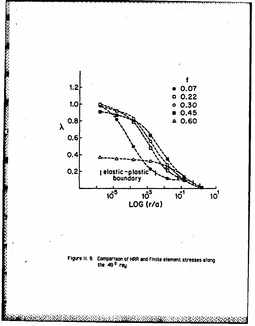
T, heelastic stress Intensity factor K [used to compute , . see Eqs. (3. 1) and(3 . 2)) has been determined from the elastic finite element"Alution bY the methoddescribed in Refs. [I and 231. It has been shown [II that KI conputed Ij this methodwill be accurate to within 3% of the correct value. For this prohlem, we havecomputed K, / . a Y = 1.23 . We com are the HRR and finite element solutions for thelow hardening material by examinin he ratio X = U, U along the 490 ray whereU is the equivalent stress obtained from the nuMficai soluflon. The results are.-.-: shown in Fig. 9.
For the elastic finite element analysis we know, by considering the analticsolution for o (gjven by the I/ /r elas ic term in the region near thecrack tIp),that the error in a increases as the crack tip is approached. The error is about 20%in those elements nearest the crack tip but is less than 15% for rla > 10- . Asdiscussed in subsection (b) above, similar behaviour regarding the accuracy of U canbe expected from the elastic-pl3tic finite element solution. As a result, we can bereasonably confident that the difference between U and U at points for which X< 0.8 can not be caused solelu I inaccurac, in the numMical solution. The HRRsolution provides an accurate r e~ entat Ion of-the near tip stress field over the range./a< p where r Is u .nnown. o/ever, from Fig. 9 we can easily determine an upperttoundan b using the criterion that the HRR solution can be considered to represent.-thme stressel only at points for which X > 0.8.
By comparing the X curves for f equal to 0.07, 0.22, and 0.3 in Fig. 9, it can beseen that p rncreases in magnitude as the applied load is Increased. However, thesecurves shdw that the HRR solution represents the stress field only over a very smallportloi of the plastic zone. For example, at f= 0.3 the elastic-plastic boundary alongthe 349 rag Is at r/a a 0.15 but the HRF solution is certainly not valid beyond r/a
As the load is Increased above 0.45 the numerical solution for the stress field
at the crack tip begins to differ increasinglu from the HRR solution. For example,consider the curve corresponding tof = 0.6. This is expected because the plastic zonehas extended to the ede of the plate (see Fig. 5)sj that It can no loner be regardedas embedded in an elastic field governed by tMe 1/1/r term. Therefore, the small-scaleyielding conditions assumed for the HRR solution are no longer true at these higher

MUE FEW CEPT Febuumy 4. 1986 P 15
-applied loads. From our numerical results we conclude, for this particular crackproblem, that the HRR solution does not represent the stress field were in thevicinitu of the crack tip when the applied load f exceeds about .0.5.11 a be seenfrom tie curve fcr f = 0.6 that the stress field displays the I/r sin laitg overthe range r/a < I0"z but its amplitude is no longer determined b K in Eq.(3. 2).
Similar behaviour Is exhibited bu the elastc-plastic solution for the high hardeningmaterial (ET = 18.51 G Pa). For Nis material it is found that the range over whicthe HRR solution represents the crack tip stress field is slightlu larger In size thanthat found for the low hardening material at the same applied load.
(e) Validity of the small strain and small rotation assumptions.
a The v componentsof strain are shown in Figure Q for the low- hardening materialat an applied lad of 0.3. The strains along the 49P ra are greater than 0.1 overthe range r/a <10 -3. It is clear that the assum tion of small strains is violated inthe region near the crack tip. The rotations of the elements in this region are alsolarge.
A formulation which accounts for large strains and large rot tion would be amore appropriate model. However, in our discussion (subsectIon (b)) on the effect ofthe different meshes, it was shown that changes in the solution over the region nearthe crack tip do not produce significant changes in the region awa from the crack tip.The large-strains are limited to a very small region at the crack tip. It might then beexpecte that a large strain formulation would not significantly alter the solution overmuch of the remainder of the plate.
The same conclusions cannot be drawn at higher levels of applied load, e.g. f= 0.5or greater, for which the plastic zone has reached the outer edge of the plate. Athese loads the region of large strains has increased in size (for example, r/a < 101at f= 0.6) to the extent that a large strain solution would be expected to differ fromthe small strain solution over much of the plate.
4. COMPUTING TIME AND VECTORIZATION.
In our finite element analUsis, the use of a large number of degrees of freedom,many small load steps, and a 1 i t converigence citerion is feasibre because of thespedd of the CRAY-I computer. Por example, a t ical load step involves the solutionof 1300 linear equations and requires about 0 iterations for convergence; thecomputations for such a step take onlg 1.2 c. p. u. seconds.
For both the low and the high hardening materials the size of the load incremtntswhen usi mesh A ranged from f: 10 "- at lower applied loads up to Af- 10 -. atNW n loads. The tolerance used In the convergence criterion (2.23) was set at TOL=
IT 1 and was held fixed for each load step. A this tolerance the solution for u .e,
a- and nodal forces F converged to 3 places of decimals.
Information about the computations performe usin different meshes for both thelow and high hardening materials is displayed in Table 2. Fo the same mes, th totalc. p. u. time for the low-hardening material is about twice that required for thehigh-hardening material. For a particular material, the number of iterations requiredper step is Independent of the choice of mesh and is governed only by the amount ofnonlinearltg present in the problem, Ie. on the extent of the plastic zone at the
SMI UAUL EPOT Fabkuy 4. 1196 pop 16
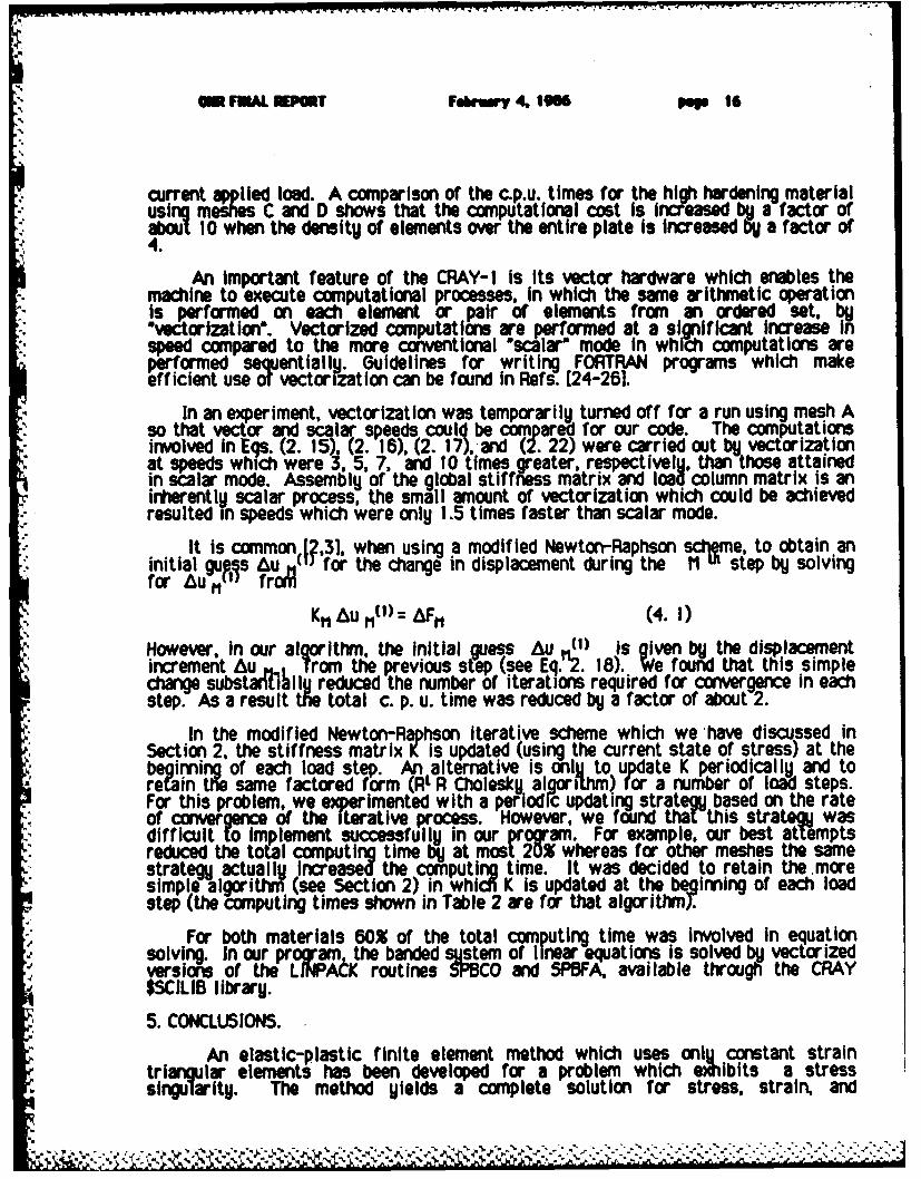
current applied load. A comparison of the c.p.u. times for the high hardening materialusing meshes C and D shows that the computational cost Is Incfeased by a factorofabct 10 when the density of elements over the entire plate is increased by a factor or4.
An important feature of the CRAY-1 is its vector hardware which enables themachine to execute computational processes, In which the same arithmetic operationis performed on each element or pair of elements from an ordered set. byvectorization'. Vectorized computations are performed at a significant increase in
speed compared to the more conventional scalar" mode in which computations areperformed sequentially. Guidelines for writing FORTRAN programs which makeefficient use of vectorization can be found in Refs. [24-261.
In an experiment, vectorization was temporarily turned off for a run using mesh Aso that vector and scalar speeds could be compared for our code. The computationsinvolved in Eqs. (2. 15), (2. 16), (2. 17), and (2. 22) were carried out by vectorlzatlonat speeds which were 3, 5, 7, and 10 times greater, respectively, than those attainedin scalar mode. Assembly of the global stifffness matrix and load column matrix is anirerently scalar process, the small amount of vectorization which could be achievedresulted in speeds which were only 1.5 times faster than scalar mode.
It is common.[?,31, when using a modified Newton-Raphson sctteme, to obtain aninitial gu¢.s Au for the change in displacement during the M L step by solvingfor Au ,, frotd
K"Au M(l) = AFM (4. 1)
However, in our alqorithm, the Initial guess Au (1) is given by the displacementincrement Au Trom the previous step (see Eq.2. 18). We found that this simplechange subst 11till reduced the number of iterations required for convergence In eachstep. As a result te total c. p. u. time was reduced by a factor of about 2.
In the modified Newton-Raphson iterative scheme which we have discussed inSection 2. the stiffness matrix K is updated (using the current state of stress) at thebeoining of each load step. An alternative is oniU to update K periodically and toretain the same factored form (Rt R Cholesky algoriuhm) for a number of load steps.For this problem, we experimented with a periodic updating strategy based on the rateof convergence of the Iterative process. However, we found that this strategy wasdifficult olmplement successfully in our program. For example, our best attemptsreduced the total computing time by at most 20% whnereas for other meshes the samestrategy actually increased the computing time. It was decided to retain the.moresimple algorithm (see Section 2) in whicni K is updated at the be inning of each loadstep (the computing times shown in Table 2 are for that algorithm?
For both materials 60% of the total computing time was involved in equationsolving. In our program. the banded sgstem of linear equations is solved by vectorizedversions of the LWACK routines SPBCO and SPOFA, available through the CRAYSSCILIB library.
5. CONCLUSIONS.
An elastic-plastic finite element method which uses only constant straintriangular elements has been developed for a problem which exlibits a stresssingularity. The method yields a complete solution for stress, strain, and

ir FIlALIN PT Felrry 4, Ig* p 17
displacement which is accurate even at points which are very close to the singularity.The method does not require any spii knowledge of the form of the singularit.The load Is applied In a series of small Increments. The size of each Increment
- determined bd the load at which the next element (out of all those that are currentlyelastic) is predicted to reach yield. The nonlinear material behavior is accounted forby a modified Newton-Raphson Iterative process which ensures that the equilibriumequations are satisfied at the end of each load Increment. The solution for the
r. particular problem of a centrally cracked plate under tensile loading in a state ofplane-stress has been presented.
The finite element solution was obtained by using a mesh in which the size of theelements decreases in a geometric series as Me crack tip is approached (see Sec. 2).In section 4, it was shown that the effect of different element arrangements on theelastic-plastic solution is similar to that observed for the purely elastic Solution(Ref.[l]). Features are included in the finite element algorithm which significantlyreduce the total c.p.u. time. In addition, the finite element code was written to takeadvantage of the vectorizing capabilities of the CRAY-i computer. therebysubstantially decreasinl the computational cost. A mesh was chosen, for ourparticular problem, which provided the. best balance between accuracy andcomputational cost.
Confidence in the accuracy of the solution was gained from a comparison with theanaltic HRR (Hutchinson-Rice-Rosengren) [10,11, and 121 solution in the neighborhoodof tMe crack tip under conditions of small-scale .ieldig. It was shown that the HRRsolution represents the behavior of the crack tip stress-strain field provided theapplied average stress does not exceed about one half of the yield stress. Lderconditions of small-scale yielding, the HRR solution characterized the stress-strainfield in the vicinity of the crack tip only over a very small portion of the plastic zonelocated at the crack tip.
The method presented here could easily be extended to materials which obey apiecewise linear stress-strain law. Yield conditions other than Von Mises could alsoDe considered. Other fracture problems such as edge cracks, non-uniform loading,shear loading, cracks in bending, etc. could all be trivially handled by changing Meboundary conditions. For these problems, the influence of geometry and boundaryconditions on the HRR solution could be studied. This has applications in determiningminimum size requirements for specimens used to establish a "one parameter" fracturecriterion based on the J-integral. The method could be modified to deal with cracks ininomogeneous and/or anisotropic materials such as composites.
The method could also be extended, admittedly not without some effort, to studythe state of stress at the tip of a growing crack for which the form of the singularityis not well understood in most materials. In a broader context, problems involvingother forms of singularity such as point loads and reentrant corners could also beconsidered.
In this paper, the emphasis has been on showing that a finite element method whichuses only constant strain elements can provide a complete elastic-p lastic solution fora state of plane-stress even in the region of hiph stress gradient close to thesingJlarity. However for real plates the state of s ress in the vicinity of the cracktip is fully three dimensional. The plane-stress solution can be expected to hold onlyat distances from the crack tip which exceed the plate thickness. This means, for th§particular geometry which we have 'considered, that the solution can have physicalmeaning only over a range of about r/a >0.05. As discussed in Section 3(b), accurate
.. A . ..--
-A.::., A . .. . . , . . , -_. , , ,, > . ., . . .. . ,. . .. . . . . ..-. . . ._.. .. , ,.,., - .,.,
011 FIAL REPOT Fhrm y 4. 1966 p Is
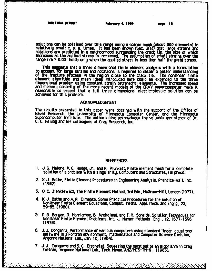
solutions can be obtained over this range using a coarse mesh (about 600 elements) inrelatively small c. p. u. times. It has been Shown (Sec. 3(e)) that large strains androtations are predicted in a neighborhood surrounding the crack tip, the size or whichn iroreases me applled stress is increased. The assumption or small strains over the
range r/a > 0.05 holds only when the applied stress is less than half the yield stress.
This suggests that a three dimensional finite element analysis with a formulationto acca nt for large strains and rotations Is required to obtain a better understandingof the fracture process in the region close to the crack tip. The nonlinear finiteelement algorithm and mesh idea! introduced here could be extended to the threedimensionar problem using constant strain tetrahedral elements. The increased speedand memory capacitu of the more recent models of the CRAY supercomputer make itreasonable to expect that a full three dimensional elastic-plastic solution can beachieved for this problem.
ACKNOWLEDGEMENT
The results presented In this paper were obtained with the support of the Office ofNaval Research the University of Minnesota Computer Center, and the MinnesotaSupercomputer Institute. The authors also acknowledge the valuable assistance of Dr.C. C. Hsiung and his colleagues at Cray Research, Inc.
REFERENCES
1. J. 6. Malone, P. G. Hodge Jr., and R. Plunkett, Finite element mesh for a completesolution of a problem with a singularity, Computers and Structures, (In press).
2. K. J. Bathe, Finite Element Procedures in Engineering Analysis, Prentice-Hall, Inc.(1982).
3. 0. C. Zlenkiewicz, The Finite Element Method, 3rd Edn., McGraw-Hill, London (1977).
4 K J. Bathe and A P. Cimento, Some Practical Procedures for the solution ofNonlinear Finite Element Equations, Comput. Meths. Appl. Mech. and Engrg., 22,59-85, ( 980).
5. P. . Bergan G. Horrigmoe, B. Krakeland, and T. H. Sorelde, Solution Techniques forNonlinear Fnlte Element Problems, Int. J. Numer. Methods Eng., 12, 1677-1696(1978).
6. J. J. Dongarra, Performance of various computers using standard linear equationssoftware I a Fortran environment, Mathematics and Computer Science Division,Argonne National Lab., Jan. 10, (1984).
7. J. J. Dwoarra and S. C. Elsenstat, Squeezing the most out of an algorithm in CrayFortran, Argonne National Lab., Tech. Memo. ANZ/MCS-TM-9, (1983).
-8" 1.

gm FWAL NP T Felry 4. 1966 Pe.; It.1.,
8. V. R. Saunders and t F. Guest Aplicatlons of the Cray- I for quantum chemistrycalculations, Comput. Phys., 26 389-395, (1982).
9. J. R Rice, Elastic-plastic fracture mechanics In The Mechanics of Fracture, ASIEWinter Annual Meeting, New York, December, (1 976).
10. J. It Rice A path Independent Integral and the approximate analysis of strainconcentration by notches and cracks, J. Appl. Mech., 35, 379-386, (1968).
11. J. R. Rice and G. F. Rosengren, Plane strain deformation near a crack tip in a powerlaw hardening material, J. Mech. Phys. Solids, 16,1-12, (1968).
12. J. W. Hutchinson, Singular behavior at the end of a tensile crack In a hardeningmaterial, J. Mech. Phys. Solids, 16, 13-31, (1968).
13. J. W. Hutchinson Plastic stress and strain fields at a crack tip, J. Mech. Phys.Solids, 16, 337-147, (1968).
14 J. R. Rice, Mathematical analysis in the mechanics of fracture, In Fracture (editedby H. Liebowitz), Vol. 2, Mathematical Fundamentals, p. 191, Acadamic Press, NewYork, (1968).
15. D. I. Tracey, Finite elements solutions for crack-tip behavior In small scale.ielding, Transactions ASE, J. Engineering Materials and Technology, 98, 146-151,-,- (I1976)..'
. 16. P. D. Hilton and J. W. Hutchinson, Plastic Intensity factors for plates, Eng. Fract.M ech.3, 435-451, ( 197 1).
17. Y. Yamada, N. Yoshimura and T. Sakurai, Plastic stress-strain matrix and itsapplication for the solution of elastic-plastic problems by the finite elementmethod, Int. J. Mech. Sc ., 10, 343-354, (1968).
18. H. It Van RI and P. G. Hodge, Jr., A slip model for finite element plasticity, J. Appl.Mech., 45, 527-532, ( 1978).
19. P. G.Hodge, Jr. and H. I. Van R1, A finite element model for plane strain plasticity,J. Appl. Mech., 46, 536-542, (1979).
.' 20. J. 6. Malone, Minnesota Supercomputer Institute Tech. Rep. (in preparation).
21. G. Yaawa, Y. Takahashi, and K. KashIma, Elastic-plastic anal Usis on stable crack-owth for center cracked plate: a benchmark study, Eng. Fract. Mech., 19, 4,755-769, (1984).
22. L. M. Kachanov, Foundations of the Theory of Plasticity, North-Holland, (1971).23. S. K Chan, I. S. Tuba and W. K. Wilson, On the finite element method in linear
fracture mechanics, Eng. Fract. Mech. , 2, 1-17, (1970).
24 P. J. Sydow, Cray computer systems technical note, Optimization Guide SN-0220,
p,.
mm Fuw. EMT F9uWY 4. 1961 pop 20
Crayj Research Inc., 1982)
25. I. Higble, Vectorization and conversion of Fortran programs for the Cray-I (CFT)compiler, Publication no. 2240207, Cray Research, Inc., (1979).
26. Cra -I computer systems, Fortran (CFT) Reference Manual, Publication * SR-0009,Crag Research, Inc.
LIST OF TABLES AND FIGURES
Table 1. Mesh parameters.Table 2. Computing times for both materials using different meshes (each program run
Is for a maximum applied load of f-0.98).Figure 1. Center cracked plate.
Figure 2. Typical mesh ( M-5, N-3).Figure 3. Equivalent stress vs. equivalent strain.
Figure 4 Load vs. gage point displacement.
Figure 5. Growth of plastic zones.
Figure 6. Growth of plastic zones near tip.
Figure 7. Equivalent stress field at an applied load of f- 0.3.
Figure 8. Strain field at an applied load of f=0.3.
Figure 9. Comparison of HRR and finite element stresses along the 49 0 ray.
A
,I
4-

number number
mesh M N of of d o. f. r
elements noe
A 49 3 1260 6a94 1319 1.0 x 10⁶a
B 33 3 876 486 91g 1.0 x10⁻⁴a
C 19 3 564 304 569 I5.56xI0 3a
D 34 6 '2064 10,98 22161x0a
Table 11. 1. Mesh parameters.
I.
k
-

m no. of total average total average
E1 e iterations per no. of no. of c. p. u. c. p. u.
(G Pa) s load step at load elements time time d.o.f.
h applied load f steps yielded (secs.) per step
mo- -,-
-o-° --
.-- 0.07 0.310.5 0.g per step (secs.)
,-. 2.372 A 16 31 37 149 608 2.0 740 1.217 13191
""2.372 B 18 32 35'151 425 2.0 416B 0.979 919
18.510 A 10 14 17 19 510 2.4 338 0.553 131918.510 B 10 14 17 19 353 2.4 178 0.504 919
18.510 C 9 15 15 18 221 2.3 55 0.299 559
18.510 D 9 16 1 6 20 373 5.0 709 1.901 2122
Table II. 2. Computing times for both materials using differentmeshes (each program run is for a maximum applied loadof f-0.98).
I
9'
.v .*p*-*%V. .-.- .. '. -&**:.~.*

"7
yI
V=V* F 30E
uz0
Dh I
2hs A Fx*0 G' F z0 B xIF0 z VZ0
Figure 11. 1. Center cracked plate.
4 h
2a
Figure 11. 2. Typical mesh 1 1-5, N=3).
.ET
YIELDSTRESS ,lsi
Figure 11. 3. Equivalent stress vs. equivalent strain.

• . -1.0
0.9
0.81
0.7
f 0.6
0.5 Experiment" Numerical~0.4
.. , 0.3
" 0.2
0.1
0.0 2.0 4.0 6.0
DISP (mm)
Figure I1. 4. Load vs. gage point displacement
-1-s/t.f * *~* . .' ~ f -t... -t...f.. -f t ' f. -t f.. f f.f tf
VV-P
y~M-VN .7
gf o.- .j.f .C-
. ......... zo . ....
X I
IX-.
M... (
.. *: ........ 0
... . .... ....---------
I ... .... .. . ....
..... .. .. ....-
..... ..... ..xxX-X-:........ ........
.. . . . . . .
... .. ..:-':X ----:.0
... ......- ~- .... * * ,..,-~- ,* ~
~ ...........
.. . . . .
. . . .. .
X.N."
.W.
XXXX 00-4
vre-eee. Veo0
Mm doe
...... ......-v X
--'- - - - - - - --4;-* . . .

ET ,. 3 7 2
22.5 f - 0.3 2.25
change of sale 820.0 0 120 2.00
I"* 490
17.5 0 4 1.75m 131*
is ;"o A 168.-. 150 - -1.50
iI: l:I 12.5 -1.25__
(GPa) (GPo)10.0 I1.00
7.5 -0.75
5.0- -050.', .*).
2.5 -0.25I ink '
0001-7 10 4S 1 0 -4 03l 10-1 10 0
, LOG (r /a)
Figure II. 7. Equivalent stress field at an applied load of f- 0.3.
k i t , . . , , , , ' , ,, . . . - . . . . . - - . .. - . . . .
101 0 12* 490
10 0 •1314
0 31S0A 168I(5f f=0.3
10
166 10
LOG r/a)
Figure u1. a. Strain fielId at an app lied load of t*O.3.
1 6. S *' ~ S 1 6 1
f1.2 - 0.07
0 0.221.0. o 0.30
4z* 0.45S0.8 '4 , A 0.60
•0.2- % elstcplsicS %%0.60
0.4- %% %
0.2- elastic -plastice%.boundary -
103 161 101LOG (rio)
Figure II. 9. Comparison of HRR and finite element stresses along
the 490o ra
-I

'S
D'S.
p.
P.
-S K-~S.
45*'S'S
.5
A