identification of machine parameters in...
TRANSCRIPT

IDENTIFICATION OF MACHINE PARAMETERS IN INDUCTION MOTOR
DRIVE
JASON CHONG NAO CHEN
This thesis is submitted as partial fulfillment of the requirement for the award of the
Bachelor Degree of Electrical Engineering (Power Systems)
Faculty of Electrical & Electronics Engineering
University Malaysia Pahang
OCTOBER, 2010

ii
“I declare that this thesis entitled „Identification of Machine Parameters in Induction
Motor Drive‟ is the result of my own research except as cited in the references”.
Signature :
Author : JASON CHONG NAO CHEN
Date : 29 NOVEMBER 2010
iv
ACKNOLWDEGEMENT
This thesis is one of the requirements in obtaining the Bachelor of Electrical
Engineering with Power Systems. I have been accompanied and supported by many
people in this journey. It is a pleasant aspect that I have now the opportunity to
express my gratitude to all of them.
First, a very special thank to my supervisor, Dr. Ahmed N Abd Alla of his
great patient and efforts in explaining things clearly. He always impressed me with
his outstanding professional conduct and his strong conviction for science. I
appreciate his consistent support from the first day I started this project. I am truly
grateful for his progressive vision about my training in science and his tolerance of
my mistakes.
By the way, I would like to thank all members of the staff of the Electrical
Engineering Department, UMP, who helped me in many ways and made my stay at
UMP pleasant and unforgettable.
Lastly, I would like to thank to all my fellow friends for giving me supports
and advice to me to keep looking forward when I am facing a lot of problems and
boundaries in completing my Final Year Project.

vi
ABSTRAK
Penggunaan motor aruhan yang meluas dalam industri disebabkan ianya
mudah dihasilkan dan ‘rugged’, boleh dipercayai dan mempunyai kebolehan yang
baik dalam permulaan pergerakan. Selaras dengan penggunaannya yang meluas
dalam industri, adalah amat penting dalam menghasilkan suatu teknik untuk
menjangkakan perubahan parameter dalam motor tersebut yang mana tidak boleh
ditentukan secara terus atas pelbagai faktor. Selepas beberapa tahun beroperasi,
model asli berdasarkan data yang dikeluarkan oleh syarikat pengeluaran tersebut itu
sendiri tidak lagi tepat. Dalam situasi berlainan, sifat sistem yang dihasilkan manusia
akan mengalami perubahan terhadap umur, tahap penggunaan ataupun perubahan
dalam parameter sistem yang dianggap pegun. Perubahan dalam parameter motor
aruhan turut dipengaruhi oleh suhu, frekuensi dan saturasi. Projek ini adalah untuk
mengenal pasti parameter mesin motor aruhan dengan menggunakan aplikasi
perisian Matlab dan pengenalan terhadap kaedah penggunaan Artificial Intelligent
(AI). Beberepa bentuk persamaan dihasilkan dan digunakan dalam membentuk
sistem tersebut. Dalam menyelesaikan persamaan tersebut, kaedah Newton Raphson
telah digunakan. Dengan menjalankan simulasi menggunakan kaedah AI yang telah
dihasilkan, parameter mesin motor aruhan boleh ditentukan. Hasil daripada nilai
parameter mesin yang telah ditentukan, keadaan motor aruhan itu sendiri boleh
dipastikan samada beroperasi secara stabil ataupun bergerak di bawah keupayaan
asal.

v
ABSTRACT
Induction motors (IM) are the most widely used motors in industry because
they are simple to build and rugged, reliable and have good self-starting capability.
Due to their wide spread in industry, it is of great importance to devise a technique
that can estimate different parameters of these motors which cannot be measured
directly for different reasons. Planners models based on the original manufacturers’
information may not be accurate enough after a few years’ operation. In other
situations, some simple man-made systems deviate from its designed behavior due to
aging, wearing out, or change in a system parameter that was assumed to be static.
Induction motor parameters change with temperature, frequency, and saturation. This
project basically is based on identifying the machine parameters of induction motor
drive by using Matlab software and introducing of Artificial Intelligent(AI) method
through it. The set of differential equation was produced and used to model the
system. To solve the set of differential equation, the Newton Raphson method have
been used. By running the simulation using the Artificial Intelligent(AI) method that
have been created, the machine parameters of the induction motor can be determine.
As the result of the machine parameters been determined, the condition of the
induction motor itself can be observe whether it still on under stable condition or
running with lower performance.

vii
TABLE OF CONTENTS
CHAPTER CONTENT PAGE
TITLE PAGE i
DECLARATION ii
DEDICATION iii
ACKNOWLEDGEMENTS iv
ABSTRACT v
ABSTRAK vi
TABLE OF CONTENTS vii
LIST OF TABLES x
LIST OF FIGURES xi
LIST OF ABBREVIATIONS xiii
LIST OF APPENDICES xiv
1 INTRODUCTION
1.1 Introduction 1
1.2 Background 2
1.3 Objective 2
1.4 Scope 3
1.5 Problem Statement 3
1.6 Thesis Organization 4
2 LITERATURE REVIEW
2.1 Introduction 6

viii
2.2 Induction Motor 7
2.2.1 Stator Construction 8
2.2.2 Stator Windings 9
2.2.3 Stator Coil Arrangement 9
2.2.4 Rotor Construction 11
2.2.5 Rotor Rotation 12
2.3 Type of System Identification 15
2.3.1 Parameter calculation from motor 15
construction data
2.3.2 Parameter estimation based on 16
steady-state motor models
2.3.3 Frequency-domain parameter 16
estimation
2.3.4 Time-domain parameter estimation 16
2.3.5 Real-time parameter estimation 17
2.4 Induction Motor Parameter Identification 17
2.4.1 Induction Motor Model 17
2.5 Matlab Software 18
2.6 Artificial Neural Network 19
2.7 Particle Swarm Optimization 20
3 METHODOLOGY
3.1 Introduction 22
3.2 Identification Process 23
3.2.1 Software 25
3.2.2 Analyze the Differential Equation 26
3.3 Particle Swarm Optimization 27
3.4 Experiments 28
4 RESULT AND DISCUSSION
4.1 Introduction 30
4.2 Interface Of The GUI 31

ix
4.3 Identification With PSO 32
4.3.1 Initialization of Identification Process 33
Without PSO
4.3.2 Rerun of Identification Process With 36
PSO
5 CONCLUSION AND RECOMMENDATIONS
5.1 Introduction 39
5.2 Conclusion 40
5.3 Recommendations for Future Work 41
REFERENCES 42
APPENDICES 46

x
LIST OF TABLES
TABLE TITLE PAGE
3.1 Comparison of Matlab GUI with others software 25
3.2 Data for Induction Motor 26
3.3 Machine Parameters 28
3.4 Real values for motor parameters and their 29
corresponding initialization ranges
xi
LIST OF FIGURES
FIGURE TITLE PAGE
2.1 Induction Motor Parts 7
2.2 Stator Construction 8
2.3 Stator Windings 9
2.4 Stator Coil Arrangement 10
2.5 Phase Of Stator Coil Arrangement 10
2.6 Pole Of Stator Winding 11
2.7 Rotor Construction 1 11
2.8 Rotor Construction 2 12
2.9 Rotor Construction 3 12
2.10 Rotor Rotation 1 13
2.11 Rotor Rotation 2 13
2.12 Rotor Rotation 3 14
2.13 Rotor Rotation 4 14
2.14 Reference Frames And Space Vector Representation 18
4.1 GUI Interface of Starting of the Program 31
4.2 GUI Interface of Short Description about the Project 31
4.3 GUI Interface of Running of the Simulation 32
4.4 Speed Vs Time of the Induction Motor 1 33
4.5 Voltage Vs Time of the Induction Motor 1 33
4.6 Stator Current Vs Time of the Induction Motor 1 34
4.7 Rotor Current Vs Time of the Induction Motor 1 34
4.8 Torque Vs Time of the Induction Motor 1 35
4.9 Speed Vs Time of the Induction Motor 2 36
4.10 Voltage Vs Time of the Induction Motor 2 36
xii
4.11 Stator Current Vs Time of the Induction Motor 2 37
4.12 Rotor Current Vs Time of the Induction Motor 2 37
4.13 Torque Vs Time of the Induction Motor 2 38
xiii
LIST OF ABBREVIATION
IM - Induction Motor
AI - Artificial Intelligent
AC - Alternating Current
NEMA - National Electrical Manufacturers Association
EMF - Electromagnetic Field
CI - Computer Intelligent
EA - Evolutionary Algorithm
ANN - Artificial Neural Network
CNS - Central Nervous System
PSO - Particle Swarm Optimization
GUI - Graphical User Interface
RLS - Recursive Least Squares

xiv
LIST OF APPENDICES
APPENDIX TITLE PAGE
A Programming for Main GUI Interface 46
B Programming for PreRun GUI Interface Coding 50
C Programming for Initialization of Identification 54
Process
D Programming for Rerun of Identification 58
Process
E Programming for State Equation 62
F Programming for PSO 65

CHAPTER 1
INTRODUCTION
1.1 Introduction
Accurate models of power plant components are essential for realistic
simulation and analysis of the dynamic performance of electrical power systems.
Generator models have received considerable attentions during last decade, but
Induction motors (IM) model are less addressed in the published papers. Induction
motors (IM) are the most widely used motors in industry because they are simple to
build and rugged, reliable and have good self-starting capability. Due to their wide
spread in industry, it is of great importance to devise a technique that can estimate
different parameters of these motors which cannot be measured directly for different
reasons. This project is being developed the equations by using the Newton Raphson
method to be run in Matlab software. By running the equations in Matlab software
programming, all the data that have been collected can be put in the equations as
actual value of the machine system. Particularly, by doing the simulation using the
Artificial Intelligent (AI) method that have been created, the machine parameters of
the induction motor can be determine. As the result of the machine parameters been
determined, the condition of the induction motor itself can be observe whether it still
on under stable condition or running with lower performance.

2
1.2 Background
This project basically is based on identifying the machine parameters of
induction motor drive by using Matlab software and introducing of Artificial
Intelligent (AI) method through it. The set of differential equation was produced and
used to model the system. To solve the set of differential equation, the Newton
Raphson method has been used. After the differential equations of the system are
solved, the three-phase currents are evaluated and compared to their counterpart in
the real system. The absolute value of the difference between the estimated and
measured currents over a certain period of time indicates how well the model
resembles the real system, and henceforth, how well the estimated parameters match
their real counterparts.
1.3 Objectives
The main objectives of this study are:
i. To identify the unknown machine parameters in induction motor.
ii. To illustrate the analytical results and to demonstrate the practical capabilities.
iii. An approaching the Artificial Intelligent (AI) method to identify the
induction motor parameters.
Through the way to achieve all the three objectives, the understanding on
how the actual induction motor behavior should be observed. The technique of
running Matlab program also needs to be understood because this project basically to
run the set of equation and model the system itself. By approaching an Artificial
Intelligent (AI) technique to run the simulation, the data or the machine parameters
of induction motor drive can be solved.

3
1.4 Scopes
Under this project sources, research and methodology that already been
planned, there is scope that being the border for this project to look more specific:
i. Three phase machine parameters of induction motor drive.
ii. Using Matlab software as the tool to run the simulation.
iii. Newton Raphson method as an equation solver.
iv. A nonlinear AI approach for identification of the induction motor parameters.
According to industrial condition for nowadays, the needs of identification
for the parameters of induction motor drive should be done because of wide spread
used of induction motor in industry. As a capable software that can be approach by
Artificial Intelligent (AI) technique, Matlab software have been chose as a tools to
solve the differential equation and run the simulation. Newton Raphson method
being chooses to solve the set of differential equation and particularly model the
system.
1.5 Problem Statement
Although some of the systems, such as motor induction system, are a man-
made system, its exact behavior cannot be determined given current and past inputs
to this system. This uncertainty in such systems is due, in large part, to the
complexity of the system in question. Planners models based on the original
manufacturers’ information may not be accurate enough after a few years’ operation.
4
In other situations, some simple man-made systems deviate from its designed
behavior due to aging, wearing out, or change in a system parameter that was
assumed to be static. Induction motor parameters change with temperature,
frequency, and saturation.
The consequence of any mismatch between the parameter values used in the
controller and those in the motor is that the actual rotor flux position does not
coincide with the position assumed by the controller. This leads to a loss of
decoupling flux and torque control. Performance of the drive therefore deteriorates
from that desired. Such models are often derived from the off-line tests and by the
estimation of each individual parameter separately and the combination of each part
of the system to get an integrated system model. System identification involves
creating a model for the system in question that, given the same input as the original
system, the model will produce an output that matches the original system output to a
certain degree of accuracy. The input or excitation to the system and model, and their
corresponding output are used to create and tune that model until a satisfactory
degree of model accuracy is reached.
1.6 Thesis Organization
This thesis basically consist of 5 chapter altogether. Chapter 1 is focus on
overall overview for the whole project what is all about including objectives, scopes
and problem statement.
For the Chapter 2, its description of literature review of the project which has
been got from different sources such as internet, journal, thesis and books.

5
Chapter 3 is consisting of methodology of the project, mostly focus on the
project flow and how it’s being organized.
Chapter 4 is about the result of the project which comes out from the program
that has been created.
The last chapter which is Chapter 5 is the conclusion for the whole project.
There are also suggestions that can be used for future implementation or upgrading
for this project.

CHAPTER 2
LITERATURE REVIEW
2.1 Introduction
The understanding on this project basically come from the research that have
been done through many type of sources such as internet, journal, thesis, books and
supervisor knowledge based on his experience before. The main thing that must be
understood is induction motor itself, the part of the induction motor and its function.
From this we can know and understand why the machine parameters of induction
motor have change. Then, the study on Matlab software as a main program that need
to be used to get and check the data acquisition. By using the Newton Raphson
method, the equations that we have can be run just by putting the data that have been
collected. Artificial Intelligent (AI) technique being used in the program that being
create in the Matlab programming to solve and specified the data needs.

7
2.2 Induction Motor
The Induction motor is a three phase AC motor and is the most widely used
machine. Its characteristic features are:
i. Simple and rugged construction.
ii. Low cost and minimum maintenance.
iii. High reliability and sufficiently high efficiency.
iv. Needs no extra starting motor and need not be synchronized.
An Induction motor has basically two parts which are stator and rotor. The
stator is made up of a number of stampings with slots to carry three phase windings.
It is wound for a definite number of poles. The windings are geometrically spaced
120 degrees apart. Two types of rotors are used in Induction motors are squirrel-
cage rotor and wound rotor. Figure 2.1 shows the induction motor parts.
Figure 2.1: Induction Motor Parts
The enclosure consists of a frame (or yoke) and two end brackets (or bearing
housings) .The stator is mounted inside the frame. The rotor fits inside the stator
with a slight air gap separating it from the stator. There is no direct physical
connection between the rotor and the stator. The enclosure also protects the
electrical and operating parts of the motor from harmful effects of the environment in
which the motor operates. Bearings, mounted on the shaft, support the rotor and

8
allow it to turn. A fan, also mounted on the shaft, is used on the motor shown below
for cooling. All loads moved by electric motors are really moved by magnetism.
The purpose of every component in a motor is to help harness, control, and use
magnetic force. When applying an AC drive system it helps to remember you are
actually applying magnets to move a load. To move a load fast does not require
more magnets, you just move the magnets fast. To move a heavier load or to
decrease acceleration time (accelerate faster) more magnets (more torque) are needed.
This is the basis for all motor applications.
2.2.1 Stator Construction
The stator and the rotor are electrical circuits that perform as electromagnets.
The stator is the stationary electrical part of the motor. The stator core of a NEMA
motor is made up of several hundred thin laminations. Figure 2.2 shows the stator
construction.
Figure 2.2: Stator Construction
9
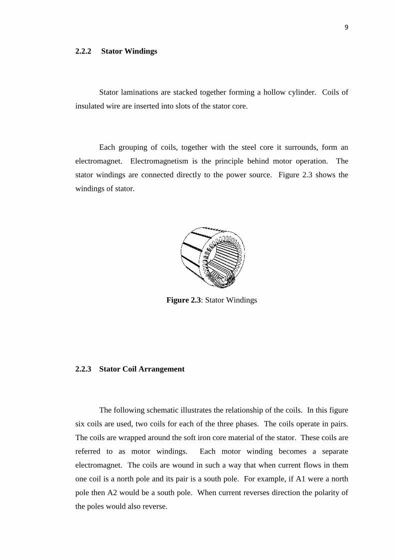
2.2.2 Stator Windings
Stator laminations are stacked together forming a hollow cylinder. Coils of
insulated wire are inserted into slots of the stator core.
Each grouping of coils, together with the steel core it surrounds, form an
electromagnet. Electromagnetism is the principle behind motor operation. The
stator windings are connected directly to the power source. Figure 2.3 shows the
windings of stator.
Figure 2.3: Stator Windings
2.2.3 Stator Coil Arrangement
The following schematic illustrates the relationship of the coils. In this figure
six coils are used, two coils for each of the three phases. The coils operate in pairs.
The coils are wrapped around the soft iron core material of the stator. These coils are
referred to as motor windings. Each motor winding becomes a separate
electromagnet. The coils are wound in such a way that when current flows in them
one coil is a north pole and its pair is a south pole. For example, if A1 were a north
pole then A2 would be a south pole. When current reverses direction the polarity of
the poles would also reverse.

10
Figure 2.4 shows the arrangement of stator coil. The stator is connected to a
3-phase AC power supply. In the following illustration phase A is connected to
phase A of the power supply. Phase B and C would also be connected to phases B
and C of the power supply respectively.
Figure 2.4: Stator Coil Arrangement
Figure 2.5: Phase Of Stator Coil Arrangement
Phase windings (A, B, and C) are placed 120° apart. Figure 2.5 shows the
phase of stator coil arrangement. In this diagram, a second set of three-phase
windings is installed. The number of poles is determined by how many times a
phase winding appears. In this figure, each phase winding appears two times. This
is a two-pole stator. If each phase winding appeared four times it would be a four-
pole stator. When AC voltage is applied to the stator, current flows through the
windings. The magnetic field developed in a phase winding depends on the direction
of current flow through that winding. Figure 2.6 shows the pole of stator winding.

11
Figure 2.6: Pole Of Stator Winding
2.2.4 Rotor Construction
The rotor is the rotating part of the electromagnetic circuit. The most
common type of rotor is the "squirrel cage" rotor. Other types of rotor construction
will be mentioned later in the course. The construction of the squirrel cage rotor is
reminiscent of rotating exercise wheels found in cages of pet rodents. Figure 2.7
shows construction of rotor.
Figure 2.7: Rotor Construction 1
The rotor consists of a stack of steel laminations with evenly spaced
conductor bars around the circumference. Figure 2.8 shows the rotor construction 2.
2-Pole Stator Winding