identificação por rfid
TRANSCRIPT

19-10-2010
1
RFID UHF
Radio Frequency
Radio frequency RFID systems usually include :
• Passive RFID’s
Mainly based on Backscatter • Active RFID’s
Based on typical wireless communications
f1
f2
Reader
(transmitter/receiver)
Tag
Ts
Ts
X
Modulator
X
19-10-2010
2
Radio Frequency
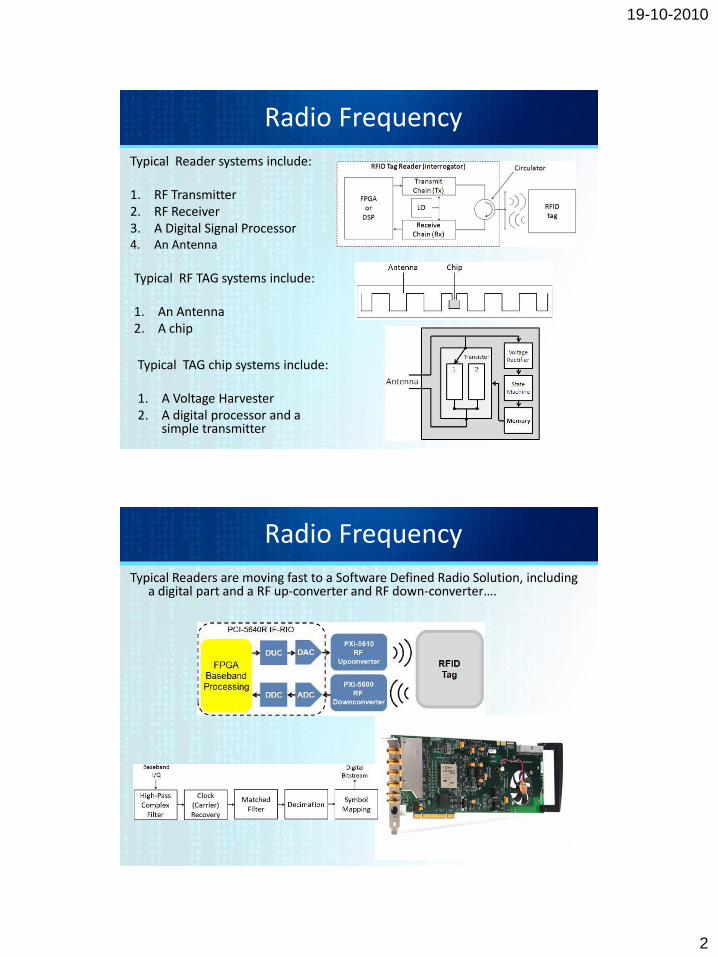
Typical Reader systems include: 1. RF Transmitter 2. RF Receiver 3. A Digital Signal Processor 4. An Antenna
Typical RF TAG systems include: 1. An Antenna 2. A chip
Typical TAG chip systems include: 1. A Voltage Harvester 2. A digital processor and a
simple transmitter
Radio Frequency
Typical Readers are moving fast to a Software Defined Radio Solution, including a digital part and a RF up-converter and RF down-converter….

19-10-2010
3
Radio Frequency
RF RFID Tags are most of the time based on electromagnetic backscatter configurations.
Backscatter is similar to radars. The TAG Antenna reflects part of an incoming electromagnetic wave back to the reader.
Electromagnetic wave are reflected by most objects that are larger than half the wavelength.
The backscatter reflection efficiency is maximized for antennas that are resonating with the incoming radar frequency.
The short wavelengths of UHF facilitate the construction of antennas with smaller dimensions and greater efficiency.
• The energy reflected from the tag is radiated into free space. A copy of this signal severely attenuated due to the free-space attenuation is received by the reader’s antenna.
• The reflected signal is returned back to the reader antenna and interpreted conveniently.
Electromagnetic Backscatter

19-10-2010
4
Far field operation
• Contrary to inductive coupling, electromagnetic backscatter operates in the far field.
• The range can be calculated based on the energy available at the transponder which is calculated using the Friis formula:
rtinTinin
eT GGr
PPGr
PGG
r
PAP
2
122
2
1224444
Backscatter RFID

19-10-2010
5
The received power can be related to the transmitted power by using the Friis formula that states:
where is the free space attenuation, and l the wavelength
UHF Electromagnetic Propagation
rtinTinin
eT GGr
PPGr
PGG
r
PAP
2
122
2
1224444
2
4
r
http://www.cdt21.com/resources/siryo3_01.asp
Electromagnetic Backscatter
• Main frequencies for backscatter are at UHF frequencies: 868 MHz (Europe) and 915 MHz (USA); and microwave frequencies: 2.5 GHz and 5.8 GHz
• The signal is modulated mainly in ASK and BPSK configurations.
• Main use for long-range systems – Distance between reader and tag > 1m
• For higher distances >15m – backscatter tag’s usually use a battery
• The tag in this situation is normally put in a stand-by mode for saving
battery time, when out of the reader range
• The battery of an active backscatter tag never provides power for the transmission of data between tag and reader. The battery is used exclusively for supply power to microchip.

19-10-2010
6
400-1000 MHz UHF RFID-Systems (UHF)
• Electromagnetic propagation • The energy collected (harvested) is related to the gain (aperture) of the
receiving antenna, which in simple terms is related to the wavelength of the received signal
• The operation range is actually dependent on the Friis formula
400-1000 MHz UHF RFID-Systems
19-10-2010
7
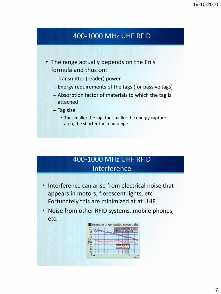
400-1000 MHz UHF RFID
• The range actually depends on the Friis formula and thus on:
– Transmitter (reader) power
– Energy requirements of the tags (for passive tags)
– Absorption factor of materials to which the tag is attached
– Tag size
• The smaller the tag, the smaller the energy capture area, the shorter the read range
400-1000 MHz UHF RFID Interference
• Interference can arise from electrical noise that appears in motors, florescent lights, etc Fortunately this are minimized at at UHF
• Noise from other RFID systems, mobile phones, etc.

19-10-2010
8
400-1000 MHz UHF RFID Directivity
• UHF is a frequency that can be used combined with directional antennas
• It is useful to increase gain of antennas, and thus range in a certain direction.
5.2 RFID UHF RFID Systems

19-10-2010
9
5900 MHz RFID Systems
5900 MHz RFID Systems
• 5900 MHz have been used significantly for over 10 years in transportation applications
– Rail car tracking
– Toll collection
– Vehicle access control

19-10-2010
10
• Operation based on Modulated backscatter
• 5.9 GHz systems operate in the “far field” long range systems
• These signals are attenuated and reflected by materials containing water or human tissue and are reflected by metallic objects
• Line of sight is not usually required for operations
5900 MHz RFID Systems
• Tags can be smaller than LF and UHF systems, and more efficient
• Compared to inductive systems, the UHF and microwave systems can have longer range, higher data rates, smaller antennas, more flexibility in form factors and antenna design
• Object penetration and no line-of-sight readability can be better for LF systems
5900 MHz RFID Systems

19-10-2010
11
5.850-5.925 GHz
Multi-Application
OBU
(retrofit installation)
87.5-107.9 MHz
FM sub carrier
800 to 900 MHz
Cellular Phone
1575.42 MHz
GPS Receiver
1800 to 1900 MHz
PCS Phone
Other ITS
Communications
Equipment
Multiple Bands
Two-way Radio
76-77 GHz
Collision
Avoidance Radar
2322.5-2345 MHz
for XM Radio
Satellite Radio band
909.75-921.75 MHz
Toll & Parking
OBU
(Add-on when
needed)
5900 MHz RFID Systems
• Approach: Active
• Bandwidth: 75 MHz (5.850 - 5.925 GHz)
• Modulation: QPSK OFDM (with 16QAM and 64QAM options) (BPSK
preamble)
• Channels: 7 - 10 MHz channels (optional combinations of 10 and 20 MHz
channels)
• Data Rate: 6, 9, 12, 18, 24, and 27 Mbps with 10 MHz Channels (3 Mbps
preamble)
• (or 6, 9, 12, 18, 24, 36, 48, and 54 Mbps with 20 MHz Channel option) (6
Mbps preamble)
• Max Tx Pwr: 28.8 dBm (at the antenna input)
• RSU EIRP: Nominal 0 - 33 dBm (1 mW - 2 W) / Max. 44.8 dBm (30 W)
• OBU EIRP: Nominal 0 - 20 dBm (1 - 100 mW) / Max. 44.8 dBm (30 W)
• RSU and OBU Sensitivity: - 82 dBm (QPSK) / - 65 dBm (64QAM)
• C/I: 4 - 6 dB (for QPSK @ 10-4 BER coded) / 16 - 17 dB (for 64QAM @
10-4 BER coded)
• Band Sharing Strategy - Frequency Coordination. Selection of alternate
channels for adjacent zones. Use CSMA to prevent interference between
users in the channel.
5900 MHz RFID Systems

19-10-2010
12
SPECTRUM USED
DATA RATE
COVERAGE
ALLOCATION STATUS
INTERFERENCE
POTENTIAL
MAXIMUM RANGE
MINIMUM SEPARATION
CHANNEL CAPACITY
POWER (Downlink)
POWER (Uplink)
12 MHz (909.75 to 921.75 MHz)
0.5 Mbps
One communication zone at a time
No protection
Many 900 MHz Phones,
Many Rail Car AEI Readers,
Many Spread Spectrum Devices,
Wind Profile Radars
300 ft (at required- 30 dBm sensitivity)
1500 ft (except where carefully planned)
1 to 2 channels
Nominally less than 40 dBm (10 W)
Nominally less than 6 dBm (< 4mW)
75 MHz
6 Mbps - 27 Mbps
Overlapping communication zones
Primary Status (high protection)
Sparsely located Military Radars,
Very Sparsely located Satellite
Uplinks
1000 m (~ 3000 ft)
50 ft (on small zone channels)
7 channels
Nominally less than 33 dBm (2 W)*
Nominally less than 33 dBm (2 W)*
902 - 928 MHz Band PARAMETERS 5850 - 5925 MHz Band
RED – Substantial Limitation
GREEN – Substantial Advantage
5900 MHz RFID Systems
Range (ft)
10
00
12
00
14
00
16
00
18
00
20
00
22
00
24
00
26
00
28
00
30
00
32
00
34
00
36
00
20
0
40
0
60
0
80
0
Data
Rate
(Mb
ps)
33
30
27
24
21
18
12
9
6
3
0
~
~
0.5 Mbps
902 - 928 MHz Band Performance Envelope
5850 - 5925 MHz Band
Performance Envelope
Emergency Vehicle Services Safety Message Services
Data Transfer and
Internet Access Services
Toll and Payment Services
(Approximate)
5900 MHz RFID Systems

19-10-2010
13
• PUBLIC SAFETY and PRIVATE APPLICATIONS share the band
• INTEROPERABILITY
• LICENSED OPERATION
• PUBLIC SAFETY INSTALLATION PRIORITY
• NON-MUTUAL EXCLUSIVITY FOR PRIVATE INSTALLATIONS
• LIMITED RANGE FOR PRIVATE OPERATIONS
• FREQUENCY COORDINATOR USED TO ASSIGN LICENSES
5900 MHz RFID Systems
5.850-5.925 GHz
Multi-Application
OBU
(connected to the IDB)
5.850-5.925 GHz
Multi-Application
OBU
(360 deg horizontal pattern)
The multi-application OBUs use a 360 deg. horizontal pattern for all applications.
909.75-921.75 MHz
Toll & Parking
OBU
(360 deg horizontal pattern)
5900 MHz RFID Systems
19-10-2010
14
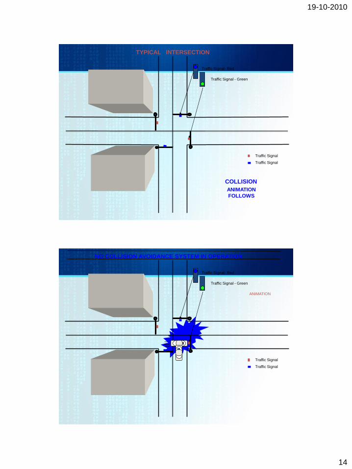
Traffic Signal
Traffic Signal
Traffic Signal - Green
Traffic Signal- Red
COLLISION
ANIMATION
FOLLOWS
TYPICAL INTERSECTION
Traffic Signal
Traffic Signal
Traffic Signal - Green
Traffic Signal- Red
NO COLLISION AVOIDANCE SYSTEM IN OPERATION
ANIMATION

19-10-2010
15
EMERGENCY VEHICLE APPROACH WARNING
VEHICLE
FRONT
EMERG.
VEHICLE
REAR
EMERG.
Note 1: The Emergency OBU transmits a warning to
ALERT other vehicles that it is coming.
In-Vehicle
Displays and
Annunciations
Traffic Signal
Traffic Signal
Emergency
Vehicle
Not to Scale
up to 1000 m (3281
ft)
OBUs on Control Ch
Emergency Vehicle
Approach Warning
Communication Zone
VEHICLE
LEFT
EMERG.
VEHICLE
RIGHT
EMERG.
ANIMATION
FOLLOWS
5.2 DSRC – DEDICATED SHORT RANGE COMMUNICATION
EMERGENCY VEHICLE APPROACH WARNING
VEHICLE
FRONT
EMERG.
VEHICLE
REAR
EMERG.
Note 1: The Emergency OBU transmits a warning to
ALERT other vehicles that it is coming.
In-Vehicle
Displays and
Annunciations
Traffic Signal
Traffic Signal
Emergency
Vehicle
Not to Scale
up to 1000 m (3281
ft)
OBUs on Control Ch
Emergency Vehicle
Approach Warning
Communication Zone
VEHICLE
LEFT
EMERG.
VEHICLE
RIGHT
EMERG. ANIMATION
5.2 DSRC – DEDICATED SHORT RANGE COMMUNICATION