ict-terranova.eu · web viewthis project has received funding from horizon 2020, european...
TRANSCRIPT
D2.2 – TERRANOVA system architecture
This project has received funding from Horizon 2020, European Union’s Framework Programme for Research and Innovation, under grant agreement
No. 761794
Deliverable D2.2TERRANOVA system
architectureWork Package 2 - System Requirements, Concept and Architecture
TERRANOVA Project
Grant Agreement No. 761794
Call: H2020-ICT-2016-2
Topic: ICT-09-2017 - Networking research beyond 5G
Start date of the project: 1 July 2017
Duration of the project: 30 months
TERRANOVA Project Page 1 of 117

D2.2 – TERRANOVA system architecture
DisclaimerThis document contains material, which is the copyright of certain TERRANOVA contractors, and may not be reproduced or copied without permission. All TERRANOVA consortium partners have agreed to the full publication of this document. The commercial use of any information contained in this document may require a license from the proprietor of that information. The reproduction of this document or of parts of it requires an agreement with the proprietor of that information. The document must be referenced if used in a publication.
The TERRANOVA consortium consists of the following partners.
No. Name Short Name Country
1 (Coordinator)
University of Piraeus Research Center UPRC Greece
2 Fraunhofer Gesellschaft (FhG-HHI & FhG-IAF) FhG Germany
3 Intracom Telecom ICOM Greece
4 University of Oulu UOULU Finland
5 JCP-Connect JCP-C France
6 Altice Labs ALB Portugal
7 PICAdvanced PIC Portugal
TERRANOVA Project Page 2 of 117

D2.2 – TERRANOVA system architecture
Document InformationProject short name and number TERRANOVA (653355)
Work package WP2
Number D2.2
Title TERRANOVA system architecture
Version v1.0
Responsible unit FhG
Involved units JCP-C, FhG, ICOM, UOULU, UPRC, ALB, PIC
Type1 R
Dissemination level2 PU
Contractual date of delivery 28.02.2018
Last update 12.03.2018
1 Types. R: Document, report (excluding the periodic and final reports); DEM: Demonstrator, pilot, prototype, plan designs; DEC: Websites, patents filing, press & media actions, videos, etc.; OTHER: Software, technical diagram, etc.2 Dissemination levels. PU: Public, fully open, e.g. web; CO: Confidential, restricted under conditions set out in Model Grant Agreement; CI: Classified, information as referred to in Commission Decision 2001/844/EC.
TERRANOVA Project Page 3 of 117
D2.2 – TERRANOVA system architecture
Document HistoryVersio
nDate Statu
sAuthors, Reviewers Description
v0.1 09.01.2018 Draft Robert Elschner (FhG-HHI)
Initial version, definition of a structure
v0.2 17.01.2018 Draft Alexandros-Apostolos A. Boulogeorgos (UPRC)
Contribution on Abbreviations and Acronyms, Section 2.3 and 5
v0.3 18.01.2018 Draft Robert Elschner (FhG-HHI)
Merge in of partner contributions
v0.4 24.01.2018 Draft Robert Elschner (FhG-HHI)
FhG contribution to Sections 2 and 3
v0.5 25.01.2018 Draft Alexandros-Apostolos A. Boulogeorgos (UPRC)
Update Abbreviations and Acronyms and Contribution on Sections 2.3 and 5
v0.6 29.01.2018 Draft Janne Lehtomaki (UOULU)
Contribution on Section 5
v0.7 31.01.2018 Draft Robert Elschner (FhG-HHI)
Merge of partner contributions
v0.8 04.02.2018 Draft Alexandros-Apostolos A. Boulogeorgos (UPRC)
Update Abbreviations and Acronyms and Contribution on Sections 2 and 5
v0.9 10.02.2018 Draft Alexandros-Apostolos A. Boulogeorgos (UPRC)
Update Abbreviations and Acronyms and Editing in Section 5
v0.10 12.02.2018 Draft Robert Elschner (FhG-HHI)
Contributions on Section 3
v0.11 18.02.2018 Draft Francisco Rodrigues(PICa)
Typo review on all sections
Contribution on Section 3
v0.12 19.02.2018 Draft Robert Elschner (FhG-HHI)
Merge of FhG-IAF contribution on section 4
v0.13 20.02.2018 Draft Alexandros-Apostolos A. Boulogeorgos (UPRC)
Update Abbreviations and editing on all sections
TERRANOVA Project Page 4 of 117

D2.2 – TERRANOVA system architecture
v0.14 26.02.2018 Draft Robert Elschner (FhG-HHI)
Introduction and conclusions, merge of JPC contribution to 5.4
v0.15 26.02.2018 Draft Alexandros-Apostolos A. Boulogeorgos (UPRC)
Contribution in Section 2.2.1, Review of Section 5.4, abbreviation update and editing on all sections
v0.16 27.02.2018 Draft Robert Elschner (FhG-HHI)
Formatting, list of figures and tables, references
v0.17 01.03.2018 Draft Robert Elschner (FhG-HHI)
Addressing remaining comments
v0.18 07.03.2018 Draft Thomas Merkle (FhG-IAF)
Contributions to section 4
v0.19 08.03.2018 Draft Robert Elschner (FhG-HHI)
Addressing remaining comments
v0.20 08.03.2018 Draft Thomas Merkle (FhG-IAF)
Contributions to section 4
v0.21 08.03.2018 Draft Alexandros-Apostolos A. Boulogeorgos (UPRC)
Contribution on Sections 1 and 6, Replace Figure 3-1, Update Abbreviations, and editing on all sections.
v0.22 09.03.2018 Draft Angeliki Alexiou (UPRC) Contribution on Sections 1 and 6
v0.23 09.03.2018 Draft Alexandros-Apostolos A. Boulogeorgos (UPRC)
Proofreading and editing on all sections.
v0.24 09.03.2018 Draft Robert Elschner (FhG-HHI)
Proofreading and editing on all sections, merging partner proofreads.
v0.25 12.03.2018 Draft Robert Elschner (FhG-HHI)
Final edits
v1.0 12.03.2018 Final Robert Elschner (FhG-HHI)
Final version, document ready for submission
TERRANOVA Project Page 5 of 117
D2.2 – TERRANOVA system architecture
Acronyms and AbbreviationsAcronym/Abbreviation Description
2G Second Generation
3G Third Generation
3GPP Third Generation Partnership Project
5G Fifth Generation
A-BFT Associate BeamForming Training
ACK Acknowledgement
ACO Analog Coherent Optics
ADC Analog-to-Digital Converter
AFC Automatic Frequency Correction
AFE Analogue FrontEnd
AGC Automatic Gain Control
AiP Antenna-in-Package
AM Amplitude Modulation
AMC Adaptive Modulation and Coding
AP Access Point
ASIC Application-Specific Integrated Circuit
ATDE Adaptive Time Domain Equalizer
ATI Announcement Transmission Interval
AWG Arrayed Waveguide Gratings
AWGN Additive White Gaussian Noise
AWV Antenna Weight Vector
BB BaseBand
BC Beam Combining
BER Bit Error Rate
BF BeamForming
BHI Beacon Header Interval
BI Beacon Interval
BOC BackOff Counter
TERRANOVA Project Page 6 of 117
D2.2 – TERRANOVA system architecture
BPSK Binary Phase Shift Keying
BRP Beam Refinement Protocol
BS Base Station
BTI Beacon Transmission Interval
CA Consortium Agreement
CAP Contention Access Period
CAUI 100 gigabit Attachment Unit Interface
CBAP Contention-Based Access Period
CapEx Capital Expenditure
CC Central Cloud
CCH Control CHannel
CDR Clock and Data Recovery
CFP C-Form Factor Pluggable
CMOS Complementary Metal–Oxide–Semiconductor
CoMP Coordination Multi-Point
COTS Commercial Off-The-Shelf
CPR Carrier Phase Recovery
CRC Cyclic Redundancy Code
CSI Channel State Information
CSMA/CA Carrier Sense Multiple Access with Collision Avoidance
CTA Channel Time Allocation
CTAP Channel Time Allocation Period
CTS Clear-To-Send
CTS-NI Clear-To-Send-Node-Information
CW Continuous Wave
D2D Device-to-Device
DAC Digital to Analog Converter
DC Direct Current
DCH Data CHannel
DDC Digital Down Conversion
DEMUX DE-MUltipleXer
DL DownLink
TERRANOVA Project Page 7 of 117

D2.2 – TERRANOVA system architecture
DMG Directional Multi-Gigabit
DMT Discrete Multi-Tone
DoA Direction of Arrival
DoF Degree of Freedom
DP Detection Probability
DP-IQ Dual Polarization In-phase and Quadrature
DPD Digital PreDistortion
DSB Dual-Side Band
DSP Digital Signal Processing
DTI Data Transfer Interval
DUC Digital Up Conversion
DWDM Dense Wavelength Division Multiplexing
EC European Commission
EDCA Enhanced Distributed Channel Access
EDMG Enhanced Directional Multi-Gigabit
E/O Electrical-Optical
ESE Extended Schedule Element
ETSI European Telecommunications Standards Institute
eWLB embedded Wafer Level Ball grid array
FAP False-Alarm Probability
FEC Forward Error Correction
FCS Frame Check Sequence
FD Full Duplex
FDD Frequency Division Duplexing
FDMA Frequency Division Multiple Access
FIFO First In First Out
FM Frequency Modulation
FPGA Field-Programmable Gate Array
FSO Free-Space Optics
FSPL Free Space Path Loss
FTTH Fiber To The Home
TERRANOVA Project Page 8 of 117
D2.2 – TERRANOVA system architecture
FWA Fixed Wireless Access
GA Grant Agreement
GaAs Gallium Arsenide
HEMT High Electron Mobility Transistor
HFT High Frequency Trading
HSPA High Speed Packet Access
HSPA+ evolved High Speed Packet Access
I/Q In-phase and Quadrature
I2C Inter-Integrated Circuit
IA Initial Access
ICF Intermediate Carrier Frequency
IEEE Institute of Electrical and Electronics Engineers
IF Intermediate Frequency
IoT Internet of Things
IM/DD Intensity Modulation/Direct Detection
IP Internet protocol layer
ISI InterSymbol Interference
ISM Industrial Scientific and Medical band
ITU International Telecommunication Union
ITU-R Radiocommunication sector of the International
Telecommunication Union
IQ COMP. In-phase and Quadrature impairments COMPensator
IQD Indoor Quasi Directional
KPI Key Performance Indicator
LDPC Low-Density Parity-Check
LO Local Oscillator
LoS Line of Sight
LTE-A Long Term Evolution Advanced
MAC Medium Access Control
MCE MAC Coordination Entity
MID Multiple sector IDentifier
TERRANOVA Project Page 9 of 117

D2.2 – TERRANOVA system architecture
MIMO Multiple Input Multiple Output
MMIC Monolithic Microwave Integrated Circuit
mmWave Millimeter Wave
MUE Mobile User Equipment
MUX MUltipleXer
MZI Mach-Zehnder Interferometer
NAV Network Allocation Vector
NETCONF NETwork CONFiguration
NI Node Information
NGPON2 Next-Generation Passive Optical Network 2
nLoS Non-Line Of Sight
NR New Radio
NRZ Non-Return to Zero
OFDM Orthogonal Frequency Division Modulation
OIF Optical Internetworking Forum
OLT Optical Line Terminal
ONUs Optical Network Units
OOK On-Off Keying
OpEx Operating Expenses
P2MP Point-to-Multi-Point
P2P Point-to-Point
PA Power Amplifier
PAM Pulse Amplitude Modulation
PBSS Personal Basic Service Set
PCB Printed Circuit Board
PCP Personal basic service set control point
PDM Polarization-Division Multiplexing
PDM-QAM Polarization Multiplexed Quadrature Amplitude
Modulation
PER Packet Error Rate
PFIS Point coordination Function Inter-frame Space
TERRANOVA Project Page 10 of 117

D2.2 – TERRANOVA system architecture
PHY PHYsical
PIN Positive-Intrinsic-Negative
PLL Phased Locked Loop
PNC Picocell Network Coordinator
PONs Passive Optical Networks
PSP Pulse Shaping Filter
PSF Primary Synchronization Signal
PtMP Point-to-Multi-Point
QAM Quadrature Amplitude Modulation
QoE Quality of Experience
QoS Quality-of-Service
QSFP Quad Small Form-Factor Pluggable
RA Random Access
RAT Radio Access Technology
RAR Random Access Response
RAU Remote Antenna Unit
RF Radio Frequency
RoF Radio over Fiber
RRM Radio Resource Management
RSRP Reference Signal Received Power
RSSI Received Signal Strength Indicator
RTS Request-To-Send
RTS-NI Request-To-Send-Node Information
RX Receiver
SC Small Cell
SD-FEC Soft-Decision Forward-Error Correction
SDM Space Division Multiplexing
SDMA Space Division Multiple Access
SDN Software Define Network
SFF Small Form Factor
SFP Small Form-Factor Pluggable
TERRANOVA Project Page 11 of 117
D2.2 – TERRANOVA system architecture
SiGe Silicon-Germanium
SISO Single Input Single Output
SLS Sector Level Sweep
SM Spatial Multiplexing
SME Small and Medium-sized Enterprise
SMF Single Mode Fiber
SNR Signal to Noise Ratio
SOTA State Of The Art
SP Service Period
SPI Serial Parallel Interface
SRC Sample Rate Conversion
SSB Single-SideBand
SSW Sector SWeep
SSW-FBCK Sector SWeep FeedBaCK
STA STAtion
STM-1 Synchronous Transport Module, level 1
STS Symbol Timing Synchronization
TAB-MAC Terahertz Assisted Beamforming Medium Access Control
TDD Time Division Duplexing
TDM Time Division Multiplexing
TDMA Time Division Multiple Access
TERRANOVA Terabit/s Wireless Connectivity by Terahertz innovative
technologies to deliver Optical Network Quality of
Experience in Systems beyond 5G
THz Terahertz
TIA TransImpedance Amplifier
TWDM Time and Wavelength Division Multiplexed
Tx Transmitter
TXOP Transmission Opportunity
UL Uplink
UE User Equipment
TERRANOVA Project Page 12 of 117

D2.2 – TERRANOVA system architecture
VCO Voltage Controlled Oscillator
VGA Variable Gain Amplifier
VLC Visible Light Communication
WLAN Wireless Local Area Network
WDM Wavelength Division Multiplexing
WiFi Wireless Fidelity
WiGig Wireless Gigabit alliance
WLBGA Wafer Level Ball Grid Array
WM Wireless Microwave
XG-PON 10 Gbit/s Passive Optical Network
XPIC Cross Polarization Interference Cancellation
YANG Yet Another Next Generation
TERRANOVA Project Page 13 of 117

D2.2 – TERRANOVA system architecture
Contents1. INTRODUCTION.....................................................................................................................22
1.1 Scope............................................................................................................................24
1.2 Structure.......................................................................................................................24
1.3 References....................................................................................................................24
2. Application scenarios and required functionalities...............................................................26
2.1 Review of application scenarios....................................................................................26
2.1.1 Scenario 1: Point-to-point.....................................................................................27
2.1.2 Scenario 2: Point-to-multi-point...........................................................................27
2.1.3 Scenario 3: Indoor quasi-omnidirectional.............................................................27
2.1.4 TERRANOVA objectives and challenges................................................................27
2.2 Required functionality of PHY layer..............................................................................28
2.2.1 Fundamental characteristics of THz systems from PHY perspective.....................28
2.2.2 Pencil beamforming..............................................................................................29
2.2.3 Adaptive modulation and coding..........................................................................29
2.2.4 Transmission through multiple frequency windows.............................................30
2.2.5 Spatially-multiplexed transmission.......................................................................30
2.3 Required functionality of MAC/RRM layer....................................................................31
2.3.1 Fundamental characteristics of wireless THz systems from MAC perspective......31
2.3.1.1 Directed THz wireless channel..........................................................................31
2.3.1.2 Heterogeneity...................................................................................................32
2.3.2 Physical Control Channels.....................................................................................32
2.3.3 UE detection and tracking.....................................................................................33
2.3.4 Interference management....................................................................................34
2.3.5 Multiple access schemes.......................................................................................35
2.3.6 Caching..................................................................................................................36
2.3.7 Handover between multiple beams......................................................................36
2.4 References....................................................................................................................37
3. Hybrid Optical/THz System Co-Design..................................................................................39
3.1 Reference system architectures....................................................................................39
3.1.1 Wireless transmission reference systems and relevant standards........................39
TERRANOVA Project Page 14 of 117
D2.2 – TERRANOVA system architecture
3.1.1.1 Scenario 1: Microwave/mmWave P2P links......................................................39
3.1.1.2 Scenario 2: P2MP microwave/mmwave, fixed wireless access (FWA)..............42
3.1.1.3 Scenario 3: Wi-Fi (IEEE 802.11ad)......................................................................43
3.1.1.4 Architecture of a wireless transmission system................................................43
3.1.1.5 Digital Baseband Processing Unit......................................................................44
3.1.1.6 ADC/DAC...........................................................................................................44
3.1.1.7 Analogue Front-End..........................................................................................44
3.1.2 Optical transmission reference systems and relevant standards..........................45
3.1.2.1 IEEE Standards for Ethernet..............................................................................45
3.1.2.2 IEEE EPON Standards, ITU-T XG-PON and NG-PON2 Recommendations..........46
3.1.2.3 OIF CFP2-ACO “Analogue Coherent” and OIF 400ZR “Coherent Interface”......47
3.1.2.4 Radio-over-fibre systems..................................................................................50
3.2 Interface implementation options................................................................................52
3.2.1 Analog media converter & digital optical link.......................................................52
3.2.2 Transparent analogue optical link.........................................................................54
3.2.3 Digital media converter and digital optical link.....................................................55
3.3 Comparative evaluation of functionality and complexity.............................................56
3.4 References....................................................................................................................56
4. THz frontend.........................................................................................................................60
4.1 Reference components/technologies...........................................................................61
4.1.1 ISM-60 GHz frontends...........................................................................................61
4.1.2 E-band frontends..................................................................................................65
4.1.3 First generation THz frontend research prototypes..............................................68
4.1.4 Beamforming frontends for 5G, 60 GHz WiGig and 300 GHz THz links.................71
4.1.4.1 ISM-60 GHz beamforming frontend [4-9], [4-10]..............................................71
4.1.4.2 5G-NR beamforming frontend at 28 GHz [4-12]...............................................72
4.1.4.3 THz phased array communications prototype at 300 GHz [4-14]......................73
4.2 Baseband up/down-conversion subsystem..................................................................74
4.2.1 Available technologies..........................................................................................75
4.2.2 Implementation options.......................................................................................77
4.2.3 Evaluation of functionality and complexity...........................................................78
4.3 Beamforming subsystem..............................................................................................78
4.3.1 Implementation options.......................................................................................78
TERRANOVA Project Page 15 of 117

D2.2 – TERRANOVA system architecture
4.3.2 Evaluation/comparison.........................................................................................80
4.4 THz antenna options.....................................................................................................81
4.4.1 Implementation options.......................................................................................81
4.4.2 Evaluation of functionality and complexity...........................................................82
4.5 References....................................................................................................................83
5. MAC/RRM protocols.............................................................................................................85
5.1 Reference MAC protocols.............................................................................................85
5.1.1 MAC protocol of IEEE 802.15.3c............................................................................85
5.1.2 MAC protocol of IEEE 802.11ad............................................................................86
5.1.3 MAC protocol of IEEE 802.11ay.............................................................................87
5.1.4 TAB-MAC...............................................................................................................89
5.2 MAC protocols..............................................................................................................90
5.2.1 Implementation options.......................................................................................90
5.2.1.1 Physical Control Channels implementation options..........................................90
5.2.1.2 UE detection and tracking.................................................................................91
5.2.1.3 Initial access......................................................................................................93
5.2.1.4 Random access..................................................................................................95
5.2.1.5 Scheduled access..............................................................................................95
5.2.1.6 Handover between multiple beams..................................................................96
5.2.2 Evaluation methodology of functionality and complexity.....................................96
5.3 RRM schemes................................................................................................................97
5.3.1 Implementation options.......................................................................................98
5.3.1.1 Dynamic Cells....................................................................................................98
5.3.2 Evaluation methodology of functionality and complexity...................................101
5.4 MetaMAC and caching schemes.................................................................................102
5.4.1 System building blocks........................................................................................103
5.4.2 MetaMAC role and description...........................................................................104
5.4.3 In-network caching schemes...............................................................................104
5.4.4 PHY caching.........................................................................................................105
5.4.5 Caching related to upper layer information........................................................105
5.4.5.1 Caching related to handover...........................................................................105
5.4.5.2 Caching related to network condition.............................................................106
5.5 References..................................................................................................................106
TERRANOVA Project Page 16 of 117

D2.2 – TERRANOVA system architecture
6. TERRANOVA candidate architectures.................................................................................109
6.1 Scenario 1: Point-to-point...........................................................................................109
6.2 Scenario 2: Point-to-multipoint...................................................................................110
6.3 Scenario 3: Indoor quasi-omnidirectional...................................................................113
6.4 References..................................................................................................................114
7. Conclusions.........................................................................................................................115
TERRANOVA Project Page 17 of 117
D2.2 – TERRANOVA system architecture
List of FiguresFigure 2.1: Application scenarios of TERRANOVA: a) Point-to-point,
b) Point-to-multi-point and c) Indoor quasi-omnidirectional.................................26Figure 3.1: The basic baseband components...........................................................................44Figure 3.2: Example of IM/DD architectures for 25G NRZ and 100G PAM4 systems [3-28].. . .46Figure 3.3: Opto-electronic realization of standard-conform Tx in CFP2-ACO IA [3-33]..........48Figure 3.4: Opto-electronic realization of standard-conform Rx in CFP2-ACO IA [3-33]..........49Figure 3.5: PHY DSP realization for a state-of-the-art digital-coherent optical transmission
system [3-36]: (a) Transmitter side DSP (egress path), (b) receiver side DSP (ingress path).........................................................................................................50
Figure 3.6: Configuration of (a) an analog, (b) a digital, (c) a digitized RoF system using RF-band transmission [3-41]..................................................................................51
Figure 3.7: General architecture of the digital optical link architecture with analog media converter based on Ethernet and/or PON compliant transceivers........................53
Figure 3.8: Realization of the analogue media converter as (a) TDM MUX and (b) FDM MUX.......................................................................................................................54
Figure 3.9: General architecture of the transparent analogue optical link architecture based on coherent CFP2-ACO transceiver modules...............................................55
Figure 3.10: General architecture of the digital optical link architecture with digital media converter based on Ethernet and/or PON compliant transceivers........................56
Figure 4.1: Typical frontend architecture at 60 GHz based on Analog Devices HMC6300/HMC6301 chipset [4-1].........................................................................62
Figure 4.2: ISM-60 GHz frontend RX/TX chipset (HMC6300/HMC6301) from Analogue Devices [4-1], (a) Tx chip, (b) Rx chip.....................................................................63
Figure 4.3: Implementation of the 60 GHz reference frontend (HMC6300/6301 chipset) in a test link [4-1]...................................................................................................64
Figure 4.4: Typical frontend architecture at E-band based on Infineon’s BGT70/BGT80 chipset [4-4]...........................................................................................................66
Figure 4.5: Implementation of the E-band reference frontend based on Infineon’s BGT70/BGT80 chipset [4-5]...................................................................................67
Figure 4.6: Research prototype frontend for the 275-325 GHz band based on the Fraunhofer IAF chipset...........................................................................................69
Figure 4.7: Fraunhofer IAF’s M170M03H frontend with Rx respectively Tx chip for the 275-325 GHz band.................................................................................................69
Figure 4.8: Fraunhofer IAF’s M185X12W multiplier-by-12 module for generating the LO at 100 GHz........................................................................................................69
Figure 4.9: Fraunhofer IAF’s M185X12W multiplier-by-12 module for generating the LO at 100 GHz........................................................................................................70
Figure 4.10: SiBeam’s 60 GHz chipset, presented in 2008.........................................................72Figure 4.11: IBM / Ericsson’s 5G beamforming transceiver chipset [4-12]................................72
TERRANOVA Project Page 18 of 117

D2.2 – TERRANOVA system architecture
Figure 4.12: Implementation of the 5G 28 GHz beamforming antenna by IBM / Ericsson [4-13].......................................................................................................73
Figure 4.13: Fraunhofer IAF’s testbed for phased array communications at 300 GHz using the M170M03H-TX/RX frontend modules [4-14]: (a) photograph of the Tx frontend, (b) block diagram of the setup....................................................74
Figure 4.14: Generic Functions of the TERRANOVA media-converter.......................................75Figure 4.15: Major options for IQ modulation and up-conversion............................................76Figure 4.16: Digital beamforming at the transmitter.................................................................79Figure 4.17: Analogue RF beamforming at the transmitter.......................................................79Figure 4.18: Hybrid beamforming at the transmitter - array of subarrays.................................80Figure 5.1: Superframe of IEEE 802.15.3c................................................................................85Figure 5.2: The components of the IEEE 802.11ad BI. In this figure, SSW-FBCK, BRP,
MID, and BC stand for sector sweep feedback, beam refinement protocol, multiple sector identifier, and beam combining, respectively...............................86
Figure 5.3: The components of the IEEE 802.11ay BI...............................................................87Figure 5.4: Beamspace channel synchronization during initial access.....................................93Figure 5.5: IA procedure..........................................................................................................94Figure 5.6: Dynamic cell network topology...........................................................................100Figure 5.7: System view of the different MetaMAC and caching building blocks..................103Figure 5.8: In-network caching schemes................................................................................105Figure 6.1: Candidate architectures for the implementation of scenario 1
(point-to-point)....................................................................................................109Figure 6.2: Candidate architecture (a) for the implementation of scenario 2
(point-to-multi-point)..........................................................................................111Figure 6.3: Candidate architecture (b) for the implementation of scenario 2
(point-to-multi-point)..........................................................................................112Figure 6.4: Candidate architecture for the implementation of scenario 3 (indoor quasi-
omnidirectional)..................................................................................................113
TERRANOVA Project Page 19 of 117

D2.2 – TERRANOVA system architecture
List of TablesTable 2.1: Mapping between the use cases presented in Section 2 and the defined
scenarios [2-1]..........................................................................................................28Table 3.1 Main features of 802.11ad.......................................................................................43Table 3.2: Possible formats and symbol rates for general architecture of the digital
optical link architecture based on Ethernet and/or PON compliant transceivers.. . .53Table 3.3: Possible formats and symbol rates for general architecture of the transparent
analog optical link architecture based on CFP2-ACO transceivers and digital ASICs..............................................................................................................55
Table 4.1: Technical key parameters of the ISM-60 GHz frontend reference [4-2], [4-3].........64Table 4.2: Technical key parameters of the E-band frontend reference [4-5], [4-6].................67Table 4.3: Technical key parameters of the THz frontend reference........................................70Table 4.4: Frontend architectures for hybrid THz/optical links.................................................77Table 6.1: Specifications of candidate architectures for the implementation of
scenario 1 (point-to-point).....................................................................................109Table 6.2: Specifications of candidate architecture (a) for the implementation of
scenario 2 (point-to-multi-point)............................................................................111Table 6.3: Specifications of candidate architecture (b) for the implementation of
scenario 2 (point-to-multi-point)............................................................................112Table 6.4: Specifications of the candidate architecture for the implementation of
scenario 3 (indoor quasi-omnidirectional).............................................................114
TERRANOVA Project Page 20 of 117
D2.2 – TERRANOVA system architecture
Executive SummaryThe present deliverable “D2.2 TERRANOVA system architecture,” focuses on the system architecture for realizing Terabit/s wireless connectivity by using Terahertz innovative technologies to deliver optical network quality of experience in systems beyond 5G. Section 2 is based on the previously submitted deliverable “D2.1 TERRANOVA system requirements” and recapitulates the identified key performance requirements for three specific technical scenarios, namely outdoor fixed point-to-point (P2P), outdoor/indoor individual point-to-multipoint (P2MP), and outdoor/indoor “quasi”-omnidirectional. Next, an overview of the required new functionalities in both physical (PHY) layer and medium access control (MAC) layers in the TERRANOVA system architecture are given. In the following Sections 3, 4 and 5, implementation options for the main constituents of the TERRANOVA architecture, i.e. the co-design of the hybrid optical/THz system (Section 3), the THz RF frontend (Section 4) and the related THz MAC and radio resource management (RRM) protocols (Section 5) are motivated and evaluated in more detail. Particular emphasis is put on the identification of technology gaps between commonly known reference systems representing the state-of-the-art (SOTA) relevant to TERRANOVA. Finally, in Section 6, the individual aspects of Sections 3, 4 and 5 are synthesized to develop specific candidate architectures for each of the three technical scenarios of TERRANOVA.
The main outcomes of the deliverable are:
An overview of the required new functionalities in both PHY layer and MAC layer to support the identified use cases of the TERRANOVA system
The identification of reference optical/THz systems, RF frontend technologies and MAC/RRM protocols representing the SOTA relevant to TERRANOVA and the identification of technology gaps with regard to the TERRANOVA system implementation
The description of implementation options for the co-design of the optical/THz system, the THz RF frontend and the THz MAC/RRM protocols
The presentation of candidate architectures for the implementation of the three specific technical use-scenarios, namely outdoor fixed point-to-point (P2P), outdoor/indoor individual point-to-multipoint (P2MP), and outdoor/indoor “quasi”-omnidirectional.
TERRANOVA Project Page 21 of 117

D2.2 – TERRANOVA system architecture
1. INTRODUCTION
Over the last years, the proliferation of wireless devices and the increasing number of bandwidth consuming internet services have significantly raised the demand for high data-rate transmission with very low latency. While the wireless world moves towards the fifth generation (5G), several technological advances, such as massive multiple-input multiple-output (MIMO) systems, full duplexing, and millimeter wave (mmW) and visible light communications (VLCs) as well as free space optics (FSOs), have been recognized as promising enablers. However, there is a lack of efficiency and flexibility in handling the huge amount of quality of service (QoS) and experience (QoE) oriented data [1-1].
Since the used frequency spectrum for 5G has limited capacity, wireless THz became an attractive complementing technology to the less flexible and more expensive optical-fibre connections as well as to the lower data rate systems, such as VLCs, microwave links, and wireless fidelity (Wi-Fi) [1-2], [1-3]. Motivated by this, the objective of the project TERRANOVA is to provide unprecedented performance excellence, not only by targeting data rates in the Tbit/s regime, but also by inherently supporting novel usage scenarios and applications, such as virtual reality, virtual office, etc., which combine the extreme data rates with agility, reliability and almost-zero response time. Additionally, in the near future, users in both rural and remote regions, in which the access is not easily established (e.g., mountains and islands), should be able to connect with high data rates up to 10 Gbit/s per user since it has been proven that access to high-speed internet for all is crucial in order to guarantee equal opportunities in the global competition. Nowadays, using solely optical fibre solutions is either infeasible or prohibitively costly. As a result, the use of wireless THz transmission as backhaul extension of the optical fibre is an important building block to bridge the ‘divide’ between rural areas and major cities and to guarantee high-speed internet access everywhere, in the beyond 5G era. Finally, the increasing number of mobile and fixed end users as well as in the industry and the service sector will require hundreds of Gbit/s in the communication to or between cell towers (backhaul) or between remote radio heads located at the cell towers and centralized baseband units (fronthaul).
In all the above-mentioned scenarios, the proposed TERRANOVA system concept is expected to be used for wireless access and backhaul networking; hence, it will influence the main technology trends in wireless networks within the next ten years and beyond. Its implementation will have to leverage breakthrough novel technological concepts. Examples are the joint-design of baseband digital signal processing (DSP) for the complete optical and wireless link, the development of broadband and highly spectral efficient radio frequency (RF) frontends operating at frequencies higher than 275 GHz, and new standardized electrical-optical (E/O) interfaces. Additionally, to address the extremely large bandwidth and the propagation properties of the THz regime, improved channel modelling and the design of appropriate waveforms, physical (PHY) layer techniques, multiple access control (MAC) schemes and antenna array configurations are required.
TERRANOVA Project Page 22 of 117

D2.2 – TERRANOVA system architecture
In this sense and with the vision to provide reliable and scalable connectivity of extremely high data rates in the Tbit/s regime at almost ‘zero-latency’, TERRANOVA proposes to extend the fibre optic systems’ QoS and QoE as well as performance reliability into the wireless domain, by exploiting frequencies above 275 GHz for access and backhaul links.
In this context, this deliverable aims at identifying the state-of-the-art implementations of a hybrid optical/THz system architecture, as well as the technology gaps for THz frontends and discussing the different RF front-end implementation options. Moreover, it provides reference physical layer schemes, MAC/RRM protocols and mechanisms and highlights their particularities and the new challenges associated with the THz specificities. Furthermore, considering the target future applications, where THz is expected to play a decisive role, three basic topological application scenarios are identified and described along with the mapping between specific use cases and applications scenarios. Based on the identified scenarios, a first selection of features, functionalities and enabling technologies requirements is possible. In this respect, the initial TERRANOVA candidate architectures are determined and a short list of their respective capabilities and features is provided.
TERRANOVA Project Page 23 of 117

D2.2 – TERRANOVA system architecture
1.1 ScopeThe objective of this deliverable, titled “D2.2 TERRANOVA system architecture” (henceforth referred to as D2.2), is to provide the required functionalities of TERRANOVA system architecture on PHY and MAC layer to support the identified use cases of the TERRANOVA system and their target KPIs. Reference architectures are identified, which provide the state-of-the-art (SOTA) as well as technology gaps with regard to the TERRANOVA system implementation. Moreover, implementation options for the TERRANOVA architecture are discussed. Finally, candidate architectures are presented, for the implementation of the three specific technical scenarios, namely outdoor fixed point-to-point (P2P), outdoor/indoor individual point-to-multipoint (P2MP), and outdoor/indoor “quasi”-omnidirectional.
1.2 Structure The structure of this document is as follows:
Section 2 (Application scenarios and required functionalities) after revising the defined technical scenarios, presents the required functionalities of the TERRANOVA system architecture on the PHY and MAC layers, which need to be implemented in order to support the identified use cases of the TERRANOVA system and their target KPIs.
Section 3 (Hybrid Optical/THz System Co-Design) discusses the reference systems (SOTA) as well as technology gaps with regard to the implementation of hybrid optical/THz systems and provides different implementation options for the TERRANOVA system.
Section 4 (THz frontend) presents reference radio frequency (RF) frontend SOTA implementations as well as technology gaps, with regard to the implementation of extremely broadband, high fractional bandwidth THz frontends and identifies different implementation options.
Section 5 (MAC/RRM protocols) presents reference MAC and radio resource management (RRM) SOTA protocols as well as technology gaps, with regard to the implementation of MAC/RRM protocols for THz systems.
Section 6 (TERRANOVA candidate architectures) combines the contents of sections 3-5 and determines the TERRANOVA candidate architectures for the implementation of the specific technical scenarios, namely outdoor fixed P2P, outdoor/indoor individual P2MP, and outdoor/indoor “quasi”-omnidirectional.
Section 7 (Conclusions) summarizes the main messages and findings of D2.2, draws conclusions and sets the consortium’s future goals.
1.3 References[1-1] A.-A. A. Boulogeorgos, A. Alexiou, T. Merkle, C. Schubert, R. Elschner, A. Katsiotis, P. Stavrianos, D. Kritharidis, P.-K. Chartsias, J. Kokkoniemi, M. Juntti, J. Lehtomaki, A. Teixeira, and F. Rodrigues, “Terahertz technologies to deliver optical network quality of experience in wireless systems beyond 5G,” to appear in IEEE Comm. Mag., 2018.
[1-2] H. J. Song and T. Nagatsuma, “Present and future of Terahertz communications,” IEEE Trans. Terahertz Sci. Technol., vol. 1, no. 1, pp. 256–263, Sep. 2011.
TERRANOVA Project Page 24 of 117

D2.2 – TERRANOVA system architecture
[1-3] A. J. Seeds, H. Shams, M. J. Fice, and C. C. Renaud, “Terahertz photonics for wireless communications,” J. Lightwave Technol., vol. 33, no. 3, pp. 579–587, Feb. 2015.
TERRANOVA Project Page 25 of 117

D2.2 – TERRANOVA system architecture
2.APPLICATION SCENARIOS AND REQUIRED FUNCTIONALITIES
This section is focused on presenting the required functionalities and challenges in the design of the TERRANOVA system architecture. In this sense, it first reviews the basic application scenarios, in which the TERRANOVA system is expected to be used. Next, it focuses on the objectives and THz-specific challenges. Finally, the PHY, MAC and RRM layers functionalities are further elaborated.
2.1 Review of application scenarios
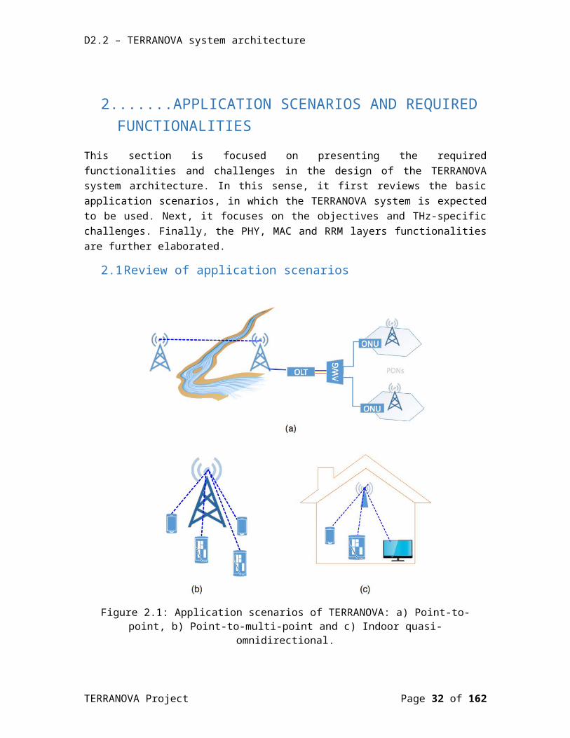
Figure 2.1: Application scenarios of TERRANOVA: a) Point-to-point, b) Point-to-multi-point and c) Indoor quasi-omnidirectional.
As illustrated in Figure 2.1 and according to TERRANOVA’s deliverable “D2.1: TERRANOVA System Requirements” [2-1], the TERRANOVA project aims to address three fundamental application scenarios, namely P2P, P2MP, and indoor quasi-omnidirectional access. For the sake of completeness, in this section, we revisit and briefly discuss these scenarios.
TERRANOVA Project Page 26 of 117

D2.2 – TERRANOVA system architecture
2.1.1 Scenario 1: Point-to-pointAs demonstrated in Figure 2.1.a, Scenario 1 considers a THz P2P connection with a single THz beam. This scenario is most relevant for stationary outdoor connections with large range and high capacity requirements. In this case, the THz beam requires no or only limited steering capability. Therefore, no beam-tracking is necessary.
2.1.2 Scenario 2: Point-to-multi-pointAs presented in Figure 2.1.b, Scenario 2 considers a THz P2MP access case, with multiple THz beams, which are used to realize individual, independent communication links. The application use cases of this scenario include stationary, nomadic or even mobile indoor and outdoor connectivity, with information broadcast or multiple independent data streams. For nomadic or mobile applications, the individual beams need to follow the receiver (RX); as a consequence, significant and dynamic beam steering and tracking capabilities are required, depending on the solid angle to be served. Moreover, this scenario demands the development and implementation of suitable handover schemes.
2.1.3 Scenario 3: Indoor quasi-omnidirectionalAs illustrated in Figure 2.1.c, Scenario 3 also considers a THz P2MP connection, with multiple THz beams. The main difference from Scenario 2 is that, the objective of this scenario is to cover a certain indoor area, room or solid angle with uninterrupted THz connectivity. In this sense, the individual THz beams should complement each other to realize complete coverage for a nomadic or mobile “virtual” link rather than serving individual links. Each base station (BS) beam serves multiple “users” within its coverage with virtual links, sharing the PHY channel by employing multiplexing techniques and protocols. Beam steering (fixed or slow) may be only needed to generate multiple, slightly overlapping beams, while nomadic and mobile applications are served with handover techniques between the different beams or different BSs. As a result, this scenario demands the utilization of coordinate multipoint (CoMP) schemes.
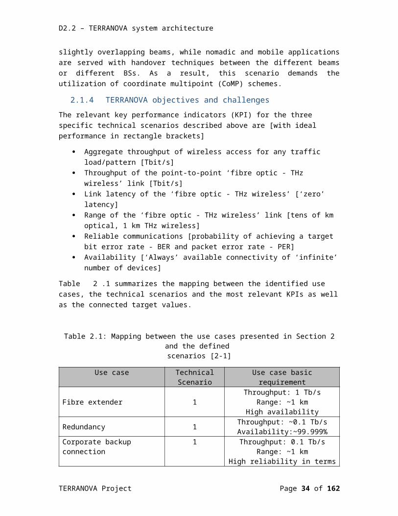
2.1.4 TERRANOVA objectives and challenges The relevant key performance indicators (KPI) for the three specific technical scenarios described above are [with ideal performance in rectangle brackets]
Aggregate throughput of wireless access for any traffic load/pattern [Tbit/s] Throughput of the point-to-point ‘fibre optic - THz wireless’ link [Tbit/s] Link latency of the ‘fibre optic - THz wireless’ [‘zero’ latency] Range of the ‘fibre optic - THz wireless’ link [tens of km optical, 1 km THz wireless] Reliable communications [probability of achieving a target bit error rate - BER and
packet error rate - PER] Availability [‘Always’ available connectivity of ‘infinite’ number of devices]
Table 2.1 summarizes the mapping between the identified use cases, the technical scenarios and the most relevant KPIs as well as the connected target values.
TERRANOVA Project Page 27 of 117
D2.2 – TERRANOVA system architecture
Table 2.1: Mapping between the use cases presented in Section 2 and the defined scenarios [2-1]
Use case Technical Scenario
Use case basic requirement
Fibre extender 1Throughput: 1 Tb/s
Range: ~1 kmHigh availability
Redundancy 1 Throughput: ~0.1 Tb/sAvailability:~99.999%
Corporate backup connection 1
Throughput: 0.1 Tb/sRange: ~1 km
High reliability in terms of BER and PER
IoT dense environment 2 and 3
Throughput: 0.1 Tb/sLatency< 1 ms
Reliability (target BER): Application dependent
Data centres 2 Throughput: 0.2 TbpsRange < 100 m
Short range THz access indoors 2 and 3 Throughput: up to 0.3 TbpsRange < 20 m
Ad-hoc access 2 and 3Throughput: 0.1 Tbps
Range ~ 500 mTarget installation time < 1 hour
Sport events, music events, etc. 2 Throughput: 0.2 TbpsRange ~ 500 m
Last mile access 2 Throughput: 0.1 Tb/sRange: ~1 km
2.2 Required functionality of PHY layer In this section, we present the PHY layer functionalities, which are necessary in order to achieve the objectives discussed in Section 2.1.4. In particular, in Section 2.2.1, we discuss the fundamental characteristics of wireless THz systems from a PHY perspective, whereas in Section 2.2.2, we discuss the need to adopt pencil beamforming schemes in order to countermeasure the high channel attenuation. Additionally, Section 2.2.3 is devoted to illustrate the concept of adaptive modulation and coding (AMC), which is expected to contribute in increasing the link data rate, while, at the same time, satisfying reliability requirements. Moreover, in Section 2.2.4, the concept of simultaneous multi-window transmission is revisited, whereas, in Section 2.2.5, the use of multiple input multiple output (MIMO) schemes is discussed in order to achieve 1 Tb/s over 1 km line of sight (LOS) link.
2.2.1 Fundamental characteristics of THz systems from PHY perspective
In this section, we focus on the fundamental characteristics of THz systems that will affect the design of the PHY layer architectures. The main characteristics can be summarized as follows:
TERRANOVA Project Page 28 of 117
D2.2 – TERRANOVA system architecture
In the THz region, because of the small wavelength, we are able to design high directional transmit antennas and receive antennas with low receive angle. These antennas are employed to countermeasure the high channel attenuation. However, at the same time, they require an extremely accurate alignment between the communication nodes.
The high material absorption in the THz band imposes limitations in the use of the non-line of sight (NLOS) communications principles. As a consequence, beam tracking schemes as well as CoMP needs to be used in order to guarantee uninterrupted communication.
Molecular absorption in the THz frequencies causes frequency- and distance-dependent pathloss, which makes specific frequency windows unsuitable for establishing a communication link. Therefore, despite the high bandwidth availability in the THz region, windowed transmission with time varying loss and per-window adaptive bandwidth usage is expected to be employed.
In order to increase the links capacity, suitable MIMO techniques in combination with beamforming should be used.
In order to countermeasure the impact of transmitter (TX) and RX misalignment and support tracking of mobile or moving user equipment (UE), adaptive beamsteering is expected to be utilized. Adaptive beamsteering enables the low-complexity link installation and guarantees that the TX and RX antennas are aligned.
In all cases, due to small wavelengths, there are high requirements on intra and inter beam coherence.
Furthermore, due to small wavelengths, multi-path fading in case of NLOS link will be quickly changing already at small spatial movements, leading to highly time-variable non-flat channel characteristics in nomadic applications.
Finally, AMC schemes should be employed in order to increase both the range and the throughput of the THz system, while, at the same time, guarantee a pre-defined degree of reliability.
2.2.2 Pencil beamforming Due to their high carrier frequencies, THz signals experience increased attenuation. This is due to pathloss as well as molecular absorption. Particularly, free space path loss grows with the square of the carrier frequency, if isotropic (receive and transmit) antennas are employed [2-2], [2-3]. Furthermore, atmospheric absorption, mainly from water vapour molecules, becomes significant in the THz band [2-3]. Finally, the large bandwidths to be used by THz communication systems lead to a significant signal-to-noise ratio (SNR) reduction, because of the wideband noise [2-2].
Beamforming is an efficient technique that can be employed in order to countermeasure the aforementioned phenomena [2-2]-[2-5]. Fortunately, the small wavelengths, and hence the small-sized antenna elements, enable the use of a large number of antenna elements, which leads to the development of powerful “beamformers”. Here, it is worth noting that beamforming can be employed either at the TX, or/and at the RX.
TERRANOVA Project Page 29 of 117

D2.2 – TERRANOVA system architecture
2.2.3 Adaptive modulation and coding It is widely known that the wireless channel experiences a time-varying behaviour. As a consequence, a wireless system that is not able to adapt to the environment and is always working for the worst channel conditions results to an inefficient management of the available spectrum. Therefore, in order to improve their efficiency and performance, modern wireless systems have to adapt their transmission to the channel conditions. In particular, they should adapt the modulation order, as well as their channel code rate in a hitless fashion, i.e., without relaxing a reliability predefined requirement, such as the BER, during changes.
As shown in [2-1], the bandwidth of the LOS THz transmission windows drastically changes even with small variations in the transmission distance, thus the development of distance-aware AMC schemes that take into account the distance-dependent bandwidth is required. Distance-adaptive AMC should be developed that employs either: (i) the entire transmission bandwidth (for short-distance communications), (ii) the central part of the transmission window (to serve close and far nodes), or (iii) the sides of the transmission window (for short-distance links) [2-6]. Within an individual transmission windows, both single-carrier (such as quadrature amplitude modulation - QAM) as well as multi-carrier modulation schemes (such as orthogonal frequency division multiplexing - OFDM and/or discrete multi-tone - DMT) should be considered to account for the required adaptation to the time varying channel conditions.
Additionally, due to small wavelengths, multi-path fading in case of NLOS links will be quickly changing already at small spatial movements leading to highly time-variable non-flat channel characteristics in nomadic applications. This phenomenon is expected to play an important role especially in indoor communications, i.e., Scenario 3.
2.2.4 Transmission through multiple frequency windowsAs described in [2-1], by utilizing multiple carriers across the different non-contiguous transmission windows, a higher aggregate capacity could be achieved. On the other hand, this also leads to an increased complexity of the system, as parallel, individually optimized THz frontends would have to be used, due to the large differences in carrier frequencies. In [2-1], initial estimations for the theoretical PHY layer data rates in the different windows by utilizing higher order modulations that help to increase the capacity at the expense of higher SNR requirements was presented. Under the assumption of considering only frequency windows above 275 GHz, no individual frequency band is able to support high data rates and achieve 1 Tbps at 1 km link distance. One option would be to consider at least parallel transmission in the first three windows including frequencies up to 450 GHz, which would be sufficient to aggregate most of the available capacity. The other option would be to extend the first frequency window to frequencies below 275 GHz to achieve a higher bandwidth and capacity. An additional advantage of the multiple frequency windows transmission would be that by selecting the available transmission windows which has the lower path loss, the antenna gain requirements can be relaxed or the available SNR increased.
TERRANOVA Project Page 30 of 117

D2.2 – TERRANOVA system architecture
2.2.5 Spatially-multiplexed transmissionAnother option, in order to achieve the 1 Tb/s over 1 km LOS link, would be to use spatial multiplexing (SM) schemes together with MIMO techniques in digital signal processing (DSP). SM can be achieved by using the following approaches:
two polarizations (factor 2); several antennas (factor N).
Due to the small wavelength of the THz wave, compact antenna arrays can be realized still satisfying the requirements of MIMO transmission. By employing a 2x2 MIMO transmission with polarization would already allow to reduce the required transmission bandwidth by factor of 2, i.e., from 200 GHz to 100 GHz, as well as the RX noise floor by 3 dB. Since each MIMO channel can use its own power amplifier (PA), this also results in a decrease of the required per-antenna directivity of 1.5 dB. Using higher NxN MIMO with antenna arrays would result in higher savings in required bandwidth and directivity; however, at the same time, the energy consumption might significantly increase.
2.3 Required functionality of MAC/RRM layerIn this section, we first identify the particularities of THz systems that bring multiple challenges to the design of MAC and RRM approaches, mechanism and protocols. Next, we discuss and briefly compare different PHY layer channel realization options and we give the trade-off between these options. Finally, we present the requirements of the basic MAC and RRM layer mechanisms, namely UE detection/tracking, interference management, caching and handover beams, as well as multiple access schemes.
2.3.1 Fundamental characteristics of wireless THz systems from MAC perspective
In this section, we focus on the fundamental characteristics of THz systems that will affect the design of the MAC mechanisms and schemes. In more detail, Section 2.3.1.1 discusses the impact of the directed THz wireless channel, whereas Section 2.3.1.2 reviews the characteristics and effect of heterogeneity in THz networks.
2.3.1.1 Directed THz wireless channelDue to the fundamental characteristics of the THz systems, which was presented in Section 2.2.1, the propagation environment suffers from sparse-scattering. This causes to the majority of the channel direction of arrivals (DoAs) to be below the noise floor. As a consequence, a channel in a wireless THz system can be established in a specific direction with a range that varies according to the directionality level.
However, the directionality of wireless THz channels results in two consequences, namely:
Blockage, which refers to the high penetration loss, due to obstacles and cannot be resolved by just increasing the transmission power; and
TERRANOVA Project Page 31 of 117
D2.2 – TERRANOVA system architecture
Deafness, which refers to the situation, in which the main beams of the transmitter and the receiver are not aligned to each other. This prevents the establishment of the communication link.
To overcome blockage, the wireless THz system is required to search for and identify alternative directed spatial channels, which are not blocked. However, this search entails a new beamforming overhead of significant amount and hence it introduces a new type of latency, in which we will refer to as beamforming latency. The MAC design for cellular networks is therefore more complicated than the one of the conventional wireless local area networks (WLANs), in which short range communications can be also established through nLOS components. Additionally, the conventional notion of cell boundary becomes questionable in these systems, due to the randomly located obstacles. As a result, a redefinition of the notion of the “traditional cell” into “dynamic cell” is required.
On the other hand, deafness has a detrimental effect on the complexity of establishing the link and causes a synchronization overhead increase. This indicates the importance of redesigning the initial access (IA) procedures.
2.3.1.2 Heterogeneity To countermeasure the physical limitations of wireless THz systems, the MAC mechanisms may simultaneously exploit both the microwave and THz bands [2-7]. This was initially presented in [2-7], where the authors provided a MAC protocol that employs microwave frequencies for establishing the control channels (CCHs), and THz frequencies for the data channels (DCH). Additionally, MAC mechanisms may need to facilitate the co-existence of several communication technologies with different coverage. In this respect, two different types of heterogeneity are observed in wireless THz networks, namely:
Spectrum heterogeneity; and Deployment heterogeneity.
By spectrum heterogeneity, we refer to the scenarios in which wireless THz UEs use both high (THz) and lower frequencies (e.g. in the microwave band). On the one hand, THz frequencies provide a massive amount of bandwidth for high data rate communications. On the other hand, the microwave frequencies are used for control message exchange, which demands much lower data rates, but higher reliability than data communications. This facilitates the deployment of wireless THz networks, due to possible omnidirectional transmission/reception of control messages, as well as higher link stability, at lower frequencies. However, the use of both microwave and THz bands in UEs increases the fabrication cost and may result to an important reduction of the mobile UE (MUE) energy autonomy. Moreover, due to the blockage and deafness effects, the establishment of a microwave CCH might not result in establishing the corresponding THz data transmission channel.
The deployment heterogeneity introduces two scenarios for THz cellular network, namely:
stand-alone networks; and integrated networks.
TERRANOVA Project Page 32 of 117

D2.2 – TERRANOVA system architecture
In the stand-alone scenario, a complete THz network (from macro to pico levels) will be deployed, whereas the integrated network solution is an amendment to existing microwave networks for performance enhancement, and includes wireless THz small cells (SCs) and/or THz hotspots [2-8].
2.3.2 Physical Control ChannelsIn general, a wireless link can be established in:
Omni-directional mode, in which both the BS and the UE are omni-directional; Semi-directional mode, in which either BS or UE is omnidirectional, and the other
operates in directional; or Fully-directional, in which both the BS and the UE are working on directional
communication modes.
The inter-cell interference in both the downlink (DL) and the uplink (UL) is significantly reduced by fully directional pencil-beam communication. On the other hand, a microwave PHY CCH can facilitate broadcasting and network synchronization.
By taking the above into account, two types of trade-offs arise, when realizing a PHY CCH, namely:
Fall-back trade off; and Directional trade off
The fall-back trade-off refers to the option of sending control messages for synchronization, cell search, user association, etc., over microwave or THz frequencies, in low data-rates. Although, the realization of PHY CCH in THz bands will enable the use of a single transceiver, resulting to lower-cost devices, the established channels would suffer from high attenuation and blockage. On the other hand, a microwave PHY CCH facilitates broadcasting and network synchronization, due to larger coverage and higher link stability compared to the corresponding THz CCHs, at the expense of higher hardware complexity and energy consumption, since a dedicated transceiver should be tuned on the microwave physical control channel.
The directional trade off refers to the option of establishing a physical channel in omni-directional, semi-directional, or fully-directional communication modes. Omnidirectional channels have a shorter communication range compared to semi-directional and fully-directional options. On the other hand, omnidirectional channels allow to all the devices within the communication range to receive the messages without any deafness problem. The semi-directional option increases the transmission range and introduces less interference to the network compared to the omni-directional option. However, mitigating the deafness problem in this case may require a spatial search that introduces extra delay. Finally, the fully-directional wireless communication mode further increases coverage and decreases the interference caused to the network at the expense of even higher spatial search overhead. Note that these trade-offs do not exist in conventional cellular networks, which operate in lower frequencies.
TERRANOVA Project Page 33 of 117
D2.2 – TERRANOVA system architecture
2.3.3 UE detection and trackingAt THz frequencies, high antenna gains are needed to overcome the large path loss and other losses. In order to support this scenario, IA, where UE discovers THz access point and forms link-layer connection, needs to support beamforming/directionality at least in one end of the link (unless communication distances are very small or very long preambles/high coding gain are used to make it easier to discover users even with omnidirectional antenna modes). However, the use of low-complexity and low-power THz devices, along with the massive number of antennas, make traditional digital beamforming based on instantaneous channel state information (CSI) very expensive and in several cases infeasible. On the other hand, the use of analog beamforming, based on predefined beam steering vectors (beam training codebook), each covering a certain direction with a certain beamwidth, is considered as a feasible and effective alternative solution. However, one of the main drawbacks of analog beamforming is the lack of multiplexing gain, which is addressed by the hybrid digital/analog beamforming architecture (for more details, please see Section 4.3).
Based on the assumed beamforming (fully digital, fully digital but low-resolution converters, hybrid, analog, etc.) multiple beams could be transmitted/received at the same time, helping to reduce IA time. Otherwise, options include sequential scanning of all possible beamforming directions at the THz access point and UE (exhaustive search), using hierarchical search, etc. The reliance on the directional transmission in the IA in the mmWave communications calls for initial cell search procedures considerably different from these followed in the existing microwave systems. In the existing microwave systems, sophisticated beamforming is used only after the IA procedures have been completed. To reduce the time overhead, a hybrid approach has been proposed in several papers, where microwave bands (omnidirectional search) are used for the BS discovery and then reverting to mmWave bands for subsequent beam alignment and data transmission. As a result, the required functions for UE detection therefore depend on the chosen approach for initial access. For example, for hierarchical search, it is needed to support successively narrower beams.
Once the THz access point (AP) and the associated UE have discovered the proper beamforming directions, the UE can be tracked in order to support nomadic mobility of UE or small movements at the transceivers of a fixed P2P link. The MAC and RRM should therefore support beam-tracking method that consumes fewer resources compared with the full exhaustive beam discovery. For example, we can search just the beam direction adjacent to the current direction; this assumes that changes are small, which may not always be the case. Motivated by this, one of the main objectives of TERRANOVA MAC protocol is to design suitable UE detection and tracking mechanisms which involve a reduced alignment overhead.
2.3.4 Interference managementIn the wireless THz networks, there are five types of interference that should be managed:
Intra-cell interference: This is the interference among UEs within a cell. It can be managed and mitigated by employing proper scheduling and beamforming designs. Pencil-beam operation substantially facilitates the intra-cell interference management strategy, due to spatial orthogonality of the directed channels of different UEs.
TERRANOVA Project Page 34 of 117

D2.2 – TERRANOVA system architecture
Inter-cell interference: This type refers to the interference among different cells. It is an important degradation factor in several conventional cellular networks; especially at the performance of devices located in cell edges, where the reuse of the same resource block in adjacent cells causes strong interference. On the other hand, in THz cellular networks, it is expected not to play a decisive role, since the scheduling based on time–frequency–space resource blocks along with fully-directional communication significantly contributes in the reduction of the inter-cell interference. In the rare case of inter-cell interference, the UEs/BSs can initiate an on-demand interference management strategy (see for example [2-9]).
Inter-layer interference: It refers to interference among different layers, macro, micro, femto, and pico, which may be more severe compared to inter-cell interference among cells of the same layer due to directional communications.
Sidelobes interference: Due to the pencil beam nature of THz transmissions, interference from sidelobes of the antenna can be ignored in many cases; similarly, interference from non-LOS transmitters can be negligible. Therefore, typical interference could be modelled with on/off behaviour with quite low probability of interference. In some cases, this could lead to noise-limited behaviour instead of interference-limited behaviour. In other cases, scheduling and proper beamforming design can be used. This also leads to challenges for MAC/RRM, as to how to extract maximum performance from systems taking into account spatial reuse.
Inter-symbol interference (ISI): In case of multipath propagation, ISI may occur.
To sum up, directional communications with pencil-beam operation drastically reduce multiuser interference in THz networks. An interesting question is whether in this case a THz network is noise-limited, as opposed to interference-limited networks. This fundamental question affects the design principles of almost all MAC layer functions. For instance, as the system moves to the noise-limited regime, the required complexity for proper resource allocation and interference avoidance functions at the MAC layer is substantially reduced. On the other hand, pencil-beam operation complicates negotiation among different devices in a network, as control message exchange may require a time consuming beam training procedure between transmitter and receiver [2-10]. In [2-11], the authors confirmed the feasibility of a pseudowired (noise-limited) abstraction in outdoor mesh networks, operating in high frequencies. However, as shown in [2-12], activating all links may cause an important performance drop compared to the optimal resource allocation in dense deployment scenarios due to non-negligible multiuser interference.
2.3.5 Multiple access schemesMAC may need to be able to combine different kinds of approaches such as contention-based approach, polling, and scheduling as in IEEE 802.11ad. With huge amounts of bandwidth available at THz frequencies, it is envisaged that simplified multiple access schemes could be developed.
Novel MAC protocols are required for THz band communication networks, since classical solutions are unable to accommodate the following characteristics:
The THz band provides devices with a very large bandwidth. As a consequence, the THz devices do not need to aggressively contend for the channel. In addition, this very large
TERRANOVA Project Page 35 of 117
D2.2 – TERRANOVA system architecture
bandwidth results in extremely high bit-rates; hence, very low transmission durations are achieved. This causes a very low collision probability.
The use of very large arrays and very narrow directional beams can also clearly reduce the multi-user interference. This comes with the cost that high-bit-rates and pencil-beams significantly increase the synchronization requirements [2-13].
As a result, a new MAC protocol need to be designed and developed that accommodates the following objectives:
To support both random and scheduled access; To countermeasure deafness, by guaranteeing alignment between the transmitter and
the receiver, through the development of receiver-initiated transmission schemes. To exploit fast-steerable narrow beams for network-wide objectives. The fast steering
and pattern control capabilities of very large antenna arrays enable new functionalities that can be exploited to control interference. For example, in the downlink, a transmitter can simultaneously send messages to multiple receivers, by transmitting time-interleaved pulses in different directions, so that the pulses intended for each user add coherently at the desired receiver, with no interference. There exists a tradeoff between user acquisition complexity and communication robustness, in terms of beam-width choice. A possible scheme to fully harness the huge antenna array is to adapt wider beamwidth during scanning phase for fast user acquisition, and intelligently steer focused thin beam for the subsequent data communication.
2.3.6 CachingThe benefits of device caching in the offloading and the throughput performance have been demonstrated in [2-14]-[2-19]. In more detail, in [2-14], the spectrum efficiency of a device to device (D2D) wireless network, in which the UEs cache and exchange content from a content library, is shown to scale linearly with the network size, provided that their content requests are sufficiently redundant. Additionally, in [2-15], the previous result is extended to the UE throughput, which, by allowing a small outage probability, is shown to scale proportionally with the UE cache size, provided that the aggregate memory of the UE caches is larger than the library size. In order to achieve these scaling laws, the impact of the D2D interference must be addressed by optimally adjusting the D2D transmission range to the UE density. In this context, in [2-16], the authors proposed a cluster-based approach in order to countermeasure the D2D interference, where the D2D links inside a cluster are scheduled with time division multiple access (TDMA). The results corroborate the scaling of the spectrum efficiency that was derived in [2-14]. In [2-17], a mathematical framework based on stochastic geometry is proposed to analyze the cluster-based TDMA scheme, and the trade-off between the cluster density, the local offloading from inside the cluster, and the global offloading from the whole network is demonstrated through extensive simulations. Finally, in [2-18], the system throughput is maximized by jointly optimizing the D2D link scheduling and the power allocation, while in [2-19], the offloading is maximized by an interference aware reactive caching mechanism. Based on the above, it is expected that device caching can significantly enhance the offloading and the delay performance of the THz cellular network, especially when the UEs exchange cached content through device to device (D2D) communication.
TERRANOVA Project Page 36 of 117

D2.2 – TERRANOVA system architecture
2.3.7 Handover between multiple beamsThe suppression of interference in THz systems with pencil-beam operation comes at the expense of more complicated mobility management and handover strategies. In contrast with the long term evolution advanced (LTE-A), frequent handover, even for fixed UEs, is a potential drawback of THz systems, due to their vulnerability to random obstacles.
As a consequence, the MAC/RRM should be able to recover from user mobility outside the coverage of the current AP or from sudden blockage such as human blockage preventing to use current AP, preferably without full initial access after current connection has been lost. Due to cost reasons, it is not expected that THz networks will cover entire areas. Therefore, after losing current THz connection it may be necessary to move to lower frequency communication networks such as WLAN/LTE. Multi-connectivity may be required.
2.4 References[2-1] EU Project TERRANOVA (grant agreement 761794), D2.1: TERRANOVA System
Requirements, public deliverable, v1.0, December 2017[2-2] S. Kutty and D. Sen, “Beamforming for millimeter wave communications: an inclusive
survey,” IEEE Communications Surveys & Tutorials, Vol. 18, Issue 2, pp. 949 – 973, Second quarter 2016.
[2-3] C. Lin and G. Ye Li, “Terahertz communications: an array of subarrays solution,” IEEE Com. Mag., vol. 54, issue 12, pp. 124 – 131, Dec. 2016.
[2-4] W. Roh, J. Seol, J. Park, B. Lee, J. Lee, Y. Kim, J. Cho, and K. Cheun, “Millimeter-Wave beamforming as an enabling technology for 5G cellular communications: theoretical feasibility and prototype results,” IEEE Com. Mag., vol. 52, issue 2, pp. 106 – 113, Feb. 2014.
[2-5] S. Han, C. I., and C. Rowell, “Large-scale antenna systems with hybrid analog and digital beamforming for millimeter wave 5g,” IEEE Com. Mag., vol. 53, issue 1, pp. 186 – 194, Jan. 2015.
[2-6] A.-A. A. Boulogeorgos, A. Alexiou, T. Merkle, C. Schubert, R. Elschner, A. Katsiotis, P. Stavrianos, D. Kritharidis, P.-K. Chartsias, J. Kokkoniemi, M. Juntti, J. Lehtomaki, A. Teixeira, and F. Rodrigues, “Terahertz technologies to deliver optical network quality of experience in wireless systems beyond 5G,” IEEE Commun. Mag., May 2018.
[2-7] X.-W. Yao, J. M. Jornet, “TAB_MAC: Assisted beamforming MAC protocol for Terahertz communication networks,” Nano Communivations Networks, vol. 9, pp. 36-42, Sep. 2016.
[2-8] C. Dehos, J. Gonzalez, A. Domenico, D. Ktenas, and L. Dussopt, “Millimeter-wave access and backhauling: The solution to the exponen- tial data traffic increase in 5G mobile communications systems?” IEEE Commun. Mag., vol. 52, no. 9, pp. 88–95, Sep. 2014.
[2-9] H. Shokri-Ghadikolaei, C. Fischione, P. Popovski, and M. Zorzi, “Design aspects of short range millimeter wave wireless networks: A MAC layer perspective,” IEEE Network, vol. 30, no. 3, May 2016.
[2-10] H. Shokri-Ghadikolaei et al., “Millimeter Wave Cellular Networks: A MAC Layer Perspective,” IEEE Trans. Commun., vol. 63, no. 10, Oct. 2015, pp. 3437–58.
TERRANOVA Project Page 37 of 117

D2.2 – TERRANOVA system architecture
[2-11] S. Singh, R. Mudumbai, and U. Madhow, “Interference Analysis for Highly Directional 60-GHz Mesh Networks: The Case for Rethinking Medium Access Control,” IEEE/ACM Trans. Net., vol. 19, no. 5, Oct. 2011, pp. 1513–27.
[2-12] H. Shokri-Ghadikolaei, L. Gkatzikis, and C. Fischione, “Beam-Searching and Transmission Scheduling in Millimeter Wave Communications,” Proc. IEEE ICC, 2015.
[2-13] W. Na, L. Park and S. Cho, "Deafness-aware MAC protocol for directional antennas," IEEE International Conference on Consumer Electronics (ICCE), Las Vegas, NV, 2013, pp. 625-626.
[2-14] N. Golrezaei, A. G. Dimakis, and A. F. Molisch, “Scaling behavior for device-to-device communications with distributed caching,” IEEE Trans. Inf. Theory, vol. 60, no. 7, pp. 4286–4298, Jul. 2014.
[2-15] M. Ji, G. Caire, and A. F. Molisch, “The throughput-outage tradeoff of wireless one-hop caching networks,” IEEE Trans. Inf. Theory, vol. 61, no. 12, pp. 6833–6859, Dec. 2015.
[2-16] N. Golrezaei, P. Mansourifard, A. F. Molisch, and A. G. Dimakis, “Base-station assisted device-to-device communications for high- throughput wireless video networks,” IEEE Trans. Wireless Commun., vol. 13, no. 7, pp. 3665–3676, Jul. 2014.
[2-17] A. Altieri, P. Piantanida, L. R. Vega, and C. G. Galarza, “On fundamental trade-offs of device-to-device communications in large wireless networks,” IEEE Trans. Wireless Commun., vol. 14, no. 9, pp. 4958–4971, Sep. 2015.
[2-18] L. Zhang, M. Xiao, G. Wu, and S. Li, “Efficient scheduling and power allocation for D2D-assisted wireless caching networks,” IEEE Trans. Commun., vol. 64, no. 6, pp. 2438–2452, Jun. 2016.
[2-19] J. Jiang, S. Zhang, B. Li, and B. Li, “Maximized cellular traffic offloading via device-to-device content sharing,” IEEE J. Sel. Areas Commun., vol. 34, no. 1, pp. 82–91, Jan. 2016.
TERRANOVA Project Page 38 of 117
D2.2 – TERRANOVA system architecture
3.HYBRID OPTICAL/THZ SYSTEM CO-DESIGNWith the vision to provide reliable and scalable connectivity of extremely high data rates in the Tbit/s regime at almost ‘zero-latency’, TERRANOVA proposes to extend the fibre optic systems’ QoS and QoE as well as performance reliability into the wireless domain, by exploiting THz frequencies predominantly above 275 GHz for access and backhaul links.
This will be achieved by co-designing hybrid optical/THz systems supporting the identified main technical scenarios with P2P, P2MP and quasi-omnidirectional links.
The development should find guidance in the co-design principle: The co-designed hybrid optical/THz systems should allow seamless integration into legacy networks on PHY and MAC layers. In order to allow this, the THz link should be designed to provide data rate compatibility with standard optical transmission systems and transceivers and should use common baseband interfaces. In a step beyond this, it could be also possible to provide fully transparent optical/THz links with common baseband signal processing.
3.1 Reference system architecturesIn this section, we first discuss and compare currently relevant systems and standards that will be used as references for the design of the TERRANOVA system architecture in “D5.1 - Report on preliminary THz RF-frontend and antenna, phased array beamforming, baseband algorithms and optical RF-frontend ready for implementation in offline tests”. Then, we present the system and interface implementation options.
As the optical/THz baseband interface has no reference equivalent, we will consider reference systems for the basic functions, i.e., standard photonic and wireless systems. Furthermore, we will consider the Radio-over-Fibre (RoF) architecture.
3.1.1 Wireless transmission reference systems and relevant standards
This section is devoted to present wireless transmission systems and standards that will be used as references throughout the project TERRANOVA. The systems are classified into the following categories:
Microwave/mmWave P2P links that corresponds in Scenario 1 and is discussed in Section 3.1.1.1;
P2MP microwave/mmwave, fixed wireless access, which refers in Scenario 2 and is presented in Section 3.1.1.2; and
Wi-Fi (IEEE 802.11ad) that corresponds in Scenario 3 and is presented in Section 3.1.1.3.
3.1.1.1 Scenario 1: Microwave/mmWave P2P linksMicrowave systems (MW)
TERRANOVA Project Page 39 of 117
D2.2 – TERRANOVA system architecture
Nowadays, the dominant transmission technology for mobile backhaul is wireless microwave (WM). It is estimated that over 60% of all sites worldwide are connected by MW, due to several benefits, such as [3-1]:
mature and field-proven technology; cost-effective backhaul over fibre and copper; rapid deployment and network rollout; and reliability based on spectrum licensing in the 6 GHz to 42 GHz range.
MW solutions are the fundamental component of LTE backhaul networks as they offer much higher internet protocol layer (IP) capacity compared to legacy MW systems. In order to continue serving the evolving LTE and LTE-A networks, IP MW backhaul solutions have to meet a number of technical requirements and demands, such as:
higher throughputs - in the order of 500 Mbit/s at tail nodes and more than 1 Gbit/s at aggregation nodes;
low latency and jitter; support of packet synchronization mechanisms for accurate frequency and phase
synchronization; advanced networking capabilities in line with software define network (SDN)
developments in other parts of the network; small form factors, which are expected to enable street level backhaul of SCs.
The key evolution challenge of MW systems has always been to increase radio data rates, while maintaining system availability and reliability within specified carrier-grade performance targets. P2P MW transmission over the air is realized on carrier frequencies from 6 to 42 GHz, and channels of 7, 14, 20, 40, and 56 MHz, as specified by various international telecommunication union (ITU) and European Telecommunications Standards Institute (ETSI) standards. Note that air is a very complex and tricky medium, due to the existence of several carrier frequency-associated factors that affect the transmission performance. These factors include the carrier frequency itself, the geographical zone, relevant climate conditions and terrain peculiarities.
The main approach for increasing data rates over the MW specified channel is the use of higher-order modulation schemes and multi-carrier schemes, such as OFDM. In more detail, in MW systems, the modulation scheme employed is based on the quadrature amplitude modulation (QAM) method, due to its high spectral efficiency. A decade ago, a typical MW modulation of 64-QAM has made possible the transmission of six bits per symbol over the same channel, achieving radio throughputs of 260 Mbit/s [3-1]. This was sufficient for the low-rate time division multiplexing (TDM) and synchronous transport module level-1 (STM-1) traffic of the second generation (2G) and early third generation (3G) mobile phone networks. Technological advances and the introduction of high speed packet access (HSPA) led to the launch of full-packet radios supporting higher-order modulation schemes up to 256-QAM. By using 256-QAM, eight bits could be transmitted concurrently; as a consequence, the throughput has been increased to 360 Mbit/s. In the last five years, modulations as high as 512-QAM and 1024-QAM (or even higher) gradually appeared and further increased system capacity supporting evolved High Speed Packet Access (HSPA+) and LTE system deployment. Nowadays, SOTA MW transceivers employ 4096-QAM, achieving actual air rates as high as 575 Mbit/s over a single 56
TERRANOVA Project Page 40 of 117

D2.2 – TERRANOVA system architecture
MHz channel [3-1]. Higher modulations up to 4096-QAM are not meant to be used as fixed modulation schemes in a MW link. They must always be combined with an advanced AMC scheme with improved switching margins. AMC enables the robust operation of the 4096-QAM in almost every case, temporarily switching to a lower modulation only when propagation conditions are adverse (e.g., during heavy storms).
Microwave bands are often limited to bandwidths of 56 to 112 MHz, for a P2P backhaul link. Thus, the latter offers up to 1 Gbps (by employing 4096-QAM). By using cross polarization interference cancellation (XPIC) technique, the throughput can be doubled. XPIC allows simultaneous transmission over the two polarization planes (i.e., horizontal and vertical) of the electromagnetic wave. Compact antenna systems, specially-designed for XPIC operation, offer compelling solutions for fully exploiting MW radio capabilities. Finally, if the transmission over both polarizations is combined with NxN MIMO transmission, then N times higher throughput can be achieved compared to the single input single output (SISO) case.
Millimeter-wave systems
The maximum throughput offered by microwave backhaul technology cannot support the demands of future wireless networks. On the other hand, millimetre-wave (mmWave) technology, and particularly E-Band technology (71-76GHz & 81-86GHz), appears to be a promising alternative.
The propagation of electromagnetic radiation in the millimetre-wavelength band is generally accompanied by higher atmospheric losses in relation to the propagation in microwave frequency bands [3-2]. E-Band systems experience higher free space path losses (FSPLs) and exhibit a significantly higher sensitivity to rain precipitation compared to conventional microwave systems. Both of these elements impact the link power budget and reduce the range of an E-band system relative to that of a conventional microwave of equal link budget.
Nevertheless, E-Band systems technology can partially compensate the disadvantage imposed by the propagation properties. The “brute force” approach of using a wide bandwidth channel enables the delivery of the very high capacities with simple, low order, modulation formats. Low order modulation formats relax the PA linearity requirements and enable higher transmit power. Today, a transmit power at the antenna port of more than 20 dBm can be achieved [3-2]. This is important to meet the required link power budget values for acceptable transmission distances. In addition, mmWave systems can benefit from high antenna gain values, even at relatively small antenna sizes. For example, more than 43 dBi and 51 dBi antenna gains can be achieved for 30 cm / 60 cm antenna radii (parabolic antennas), respectively. This facilitates the configuration of systems that reach acceptable distances with small antenna diameters, which can be deployed in a flexible and cost-effective manner.
It should be pointed out that mmWave systems in the E-band are relatively immune to molecular absorption, which is caused by atmospheric gasses, as well as, other atmospheric scattering agents, such as fog, clouds, and airborne particles, which are characterised by micrometre rather than millimetre dimension scales. Effective link lengths of P2P E-Band systems under LOS conditions can vary, depending on the required capacity and rain zone, from about 500 m up to several km.
TERRANOVA Project Page 41 of 117

D2.2 – TERRANOVA system architecture
Another important feature is that the steep propagation loss curve and narrow radiation beam width of E-band systems facilitate interference management in a high link density environment, such as urban environment. As mmWave radiation is confined to very narrow beam widths of the order of the fraction of a degree and it is attenuated strongly with distance, interference is minimised from a link to its nearby links.
From the above, it is evident that E-Band frequency links can be deployed more densely than the conventional microwave frequency links. On the other hand, E-Band links can be introduced to partially substitute microwave frequency links, reducing their density and alleviating interference in the below 38 GHz frequency bands. As a result, several country spectrum regulators view E-Band links as means for addressing microwave frequency congestion issues, which become increasingly common in major urban areas as the number of cellular base station sites grows.
State-of-the-art E-band backhaul systems can achieve throughputs of 10 Gbps, by employing channel bandwidths of up to 1.5-2GHz and modulation order of up to 256-QAM. In the case where the XPIC technology is used, throughput of 20 Gbps can be achieved [3-3], [3-4], [3-5].
3.1.1.2 Scenario 2: P2MP microwave/mmwave, fixed wireless access (FWA)
Compared to P2P coverage for the same area, P2MP technology demonstrates considerable capital expenditure (CapEx) reductions and major operating expenses (OpEx) savings, which is estimated to be more than 70%. P2MP treats each radio link independently and assigns bandwidth dynamically; thus, optimizing sector capacity planning and leveraging the radio resource-sharing nature of P2MP. Usually these systems combine frequency, time and space division multiplexing/duplexing. The DL and UL separation is based on frequency division duplexing (FDD) or time division duplexing (TDD). The DL can be time-division multiplexing (TDM), space-division multiplexing (SDM) or frequency division multiplexing (FDM), whereas the UL is based on TDMA schemes. When time division schemes are employed, unavoidably throughput is reduced compared to P2P systems.
Typical frequencies for P2MP are 10.5/26/28 GHz. Furthermore, a sector capacity of 1.8 Gbps aggregated with 112 MHz channel bandwidth, latency of 1 ms and sector density of >60 terminal stations have been currently achieved [3-6], [3-7], [3-8], [3-9]. On the networking side, SDN-based network automation has recently been employed within the microwave industry, with the initial focus being on automation and centralization of network and service configurations. Both open and standardized interfaces are now becoming available, which will enable the development of SDN applications, especially in multi-technology or multi-vendor environments (network slicing) [3-3], [3-10]. The network configuration (NETCONF) protocol and yet another next generation (YANG) models are currently the preference for SDN network automation.
P2MP systems are also used in FWA applications for corporate and residential access. Long range (~10 km) links for rural areas can be deployed. Mobile network operators view FWA as the first application for 5G in mmWave spectrum [3-11]. FWA is a compelling first application for several reasons. Operators can deliver high speed access to homes, apartments, or businesses with less cost and time compared to traditional cable and fibre-to-the-home (FTTH) installations.
TERRANOVA Project Page 42 of 117
D2.2 – TERRANOVA system architecture
This opens new markets that previously were available only to satellite, fibre, or cable providers. An additional attraction is the potential to directly extend FWA infrastructure investment towards providing 5G mobile access.
3.1.1.3 Scenario 3: Wi-Fi (IEEE 802.11ad)IEEE 802.11ad (or WiGig after the Wireless Gigabit Alliance that endorses it) provides higher data throughput and lower latency solutions in less crowded spectrum bands by operating in the 60 GHz mmWave band [3-12]. Four ultra-wideband channels are used in the 60 GHz band, each one of them having 2.16 GHz bandwidth. WiGig delivers data rates up to 7 Gbit/s. The 60 GHz signal cannot typically penetrate walls but can propagate off reflections from walls, ceilings, floors and objects using beamforming technology. Further, by employing beamforming, narrow beams are formed in 60 GHz spectrum, allowing several devices to simultaneously use the same channel. The table below gives a summary of the main features of 802.11ad:
Table 3.2 Main features of 802.11ad
802.11AD CHARACTERISTICS DESCRIPTIONOperating frequency range 60 GHz ISM bandMaximum data rate 7 GbpsTypical distances 1 - 10 mAntenna technology Uses beamformingModulation formats Various: single carrier and OFDM
The IEEE 802.11ad uses a MAC layer standard that is shared with current 802.11 standards to enable session switching between 802.11 Wi-Fi networks operating in the 2.4 GHz, and 5 GHz bands with those using the 60 GHz WiGig bands. In this way, seamless transition can occur between the systems.
.
3.1.1.4 Architecture of a wireless transmission systemA typical architecture for a wireless transmission system is shown in Figure 3.2 and is composed of the following main parts:
Digital baseband processing units; ADC/DAC; and Analogue frontend.
TERRANOVA Project Page 43 of 117

D2.2 – TERRANOVA system architecture
Figure 3.2: The basic baseband components.
3.1.1.5 Digital Baseband Processing UnitAs illustrated in Figure 3.2, the main parts of the baseband unit of a transceiver are the MAC and PHY layer blocks. Within the MAC layer, DL/UP mapping is performed, i.e., the proper timeslots are created for the traffic. Forward error correction (FEC) coding is employed in order to increase the quality of transmission. Furthermore, constellation mapping/demapping is performed. Within the PHY layer, advanced signal processing algorithms are implemented for the optimum exploitation of the available spectrum, highest possible transmission, synchronization, etc.
3.1.1.6 ADC/DACAnalogue signals received at the analogue frontend (AFE) are sampled, then converted to digital, and finally read in the baseband processing unit in the RX direction. Similarly, signals output from the baseband unit are converted to analogue and fed to the AFE in the TX direction. The ADC/DAC part plays an important role in increasing throughputs and accordingly bandwidths, as their technology imposes the limit on the achievable sampling rate.
3.1.1.7 Analogue Front-End
TERRANOVA Project Page 44 of 117
D2.2 – TERRANOVA system architecture
Up-conversion of the analogue signal takes place to either an intermediate frequency (IF) or directly to the final RF frequency, in the TX direction. Respectively, down-conversion from IF/RF to baseband frequency is performed in the Rx direction. The AFE is feeding the antenna through a duplexer in order to use a single antenna for both transmission and reception.
3.1.2 Optical transmission reference systems and relevant standards
For optical communication systems, the relevant standardization bodies are the Institute of Electrical and Electronics Engineers (IEEE), the Optical Internetworking Forum (OIF) and the ITU. Thereby, the standardization (or de-facto standardization by multi-source agreements (MSA) or implementation agreements) differentiates the optical line side interfaces and systems (e.g., Ethernet [3-13], [3-14], PON [3-15], [3-16], [3-17], [3-18], OIF 400ZR [3-19]), the electrical client side interfaces (e.g. IEEE CAUI [3-20], OIF CEI [3-21]) and the pluggable modules (e.g., XFP MSA [3-22], CFP MSA [3-23], SFP/QSFP MSAs [3-24]). In the following, the different relevant standards will be shortly discussed with regard to their relevance for the design of the hybrid optical/THz TERRANOVA system architecture.
3.1.2.1 IEEE Standards for Ethernet These standards cover PHY and MAC as well as management parameters for optical fixed line data communication (such as intensity modulation and direct detection - IM/DD) transmission systems up to 100 Gb/s (802.3bm – 2015 [3-13]) and very recently also up to 400 Gb/s (IEEE 802.3bs – 2017 [3-14]). Additionally, there are several widely accepted MSAs closely connected to the IEEE Ethernet standards, such as the CWDM4 MSA [3-25] and the PSM4 MSA [3-26].
The standardization covers system architectures and transceiver specifications for different transmission media [3-27]. From a PHY layer perspective, all single-mode optical fibre (SMF)-based standards comprise similar IM/DD transceiver architectures exemplarily shown in Figure3.3 [3-28]. At the TX, a continuous wave (CW) laser signal is intensity modulated, using an Mach–Zehnder interferometer (MZI), while the DD RX consists of a single-ended photodiode. The modulation formats, which are employed, are non-return to zero (NRZ) and 4PAM at symbol rates of about 10 GBd, 25 GBd and 50 GBd. The gross rates of 100 Gb/s and 400 Gb/s are achieved by parallel implementation of several transceivers within a single module, with the individual sub-channel transmitted either on parallel fibres or wavelengths. The standardized transmission lengths reach from 500m up 40 km [3-27].
As presented in Figure 3.3, the required signal processing for each NRZ subchannel is typically performed in an analogue fashion only using analogue electronic continuous time linear equalization (CTLE) and clock and data recovery (CDR) circuits. This is possible since the client side interfaces directly support the same symbol rates as the optics side, e.g., 4x25 GBd for QSFP28 [3-29], CFP4 [3-30] or CFP2 [3-31] module sizes or 10x 10 GBd for CFP [3-32] and CFP2 [3-31].
To reach higher symbol rates on the line side, analogue multiplexing (MUX) circuits are used, generating 50 GBd NRZ signal from two 25 GBd NRZ signals. Similarly, a 4-PAM signal can be multiplexed from two NRZ signals either in analogue electrical or in optical domain [3-28].
TERRANOVA Project Page 45 of 117

D2.2 – TERRANOVA system architecture
Figure 3.3: Example of IM/DD architectures for 25G NRZ and 100G PAM4 systems [3-28].
3.1.2.2 IEEE EPON Standards, ITU-T XG-PON and NG-PON2 Recommendations
Recent standards under deployment either from IEEE or from ITU-T predict line rates of 10 Gb/s using IM. IEEE 802.3av-2009 also known as 10G EPON [3-15] and ITU-T XG-PON G987.1 [3-17] share the dual rate possibility of 2.5 and 10 Gb/s both on upstream and downstream using single channel and thus being only TDM networks.
ITUT-T G989.2 also known as NG-PON2 [3-18] differentiates from the other 10-Gb/s standards for predicting wavelength division multiplexing (WDM). NG-PON2 can use 4 or 8 channels in both downstream and upstream direction. First implementations and field trials comprise 4 channels at 10 Gb/s which represent an aggregated bandwidth of 40 Gb/s in each direction.
The current choice for pluggable optoelectronic transceivers for 10 Gb/s is the standard format XFP [3-22]. Typically, the XFP circuitry comprises data lanes for transmitter and receiver and signalling to control the laser and photodiode, monitor the transceiver and an inter-integrated circuit (I2C) bus. Internally the architecture consists on the transmitter side on a laser driver either for external or direct modulation, a CDR for the receiver and a micro-controller to control the optical module utilized and monitor the XFP. Current optic modules for the 10 Gb/s standard consist of cooled or un-cooled lasers (cooled is the most common option) that in the majority of the cases are externally modulated with intensity modulators. On the receiver side, a single avalanche photodiode is the choice since PONs have to operate on a high link budget and thus the receiver should achieve higher sensitivities than positive-intrinsic-negative (PIN) diodes can reach.
IEEE 802.3 NG-EPON task force
TERRANOVA Project Page 46 of 117

D2.2 – TERRANOVA system architecture
Standardization bodies are already working on the future generation PONs that will go beyond the 10 Gb/s. One example is the task force created by IEEE for the so-called NG-EPON that drafted the first guidelines in 2015 [3-16]. In short, the goal is to reach 100 Gb/s links using time and wavelength division multiplexed (TWDM) PONs with multilevel modulation such as 4-PAM. The choice of 4-PAM or duo-binary will enable a capacity increase, while, at the same time, will maintain the optical hardware relatively low-cost and therefore affordable for PON scenarios.
3.1.2.3 OIF CFP2-ACO “Analogue Coherent” and OIF 400ZR “Coherent Interface”
Only recently, OIF ‘de facto standardized’ also the line-side for optical fixed line telecom (coherent) transmission systems. In the OIF IA CFP2-ACO, the analogue opto-electronics required for coherent metro and longhaul transmission (some hundreds to some thousands of kilometres) is standardized for the CFP2 form factor [3-33], while OIF MSA 400ZR is currently defining the DSP application-specific integrated circuit (ASIC) properties needed for interoperability over 80 km coherent transmission [3-19].
The CFP2-ACO standardized transmitter part is shown in Figure 3.4. It consists basically of a TX laser and a dual-polarization in-phase and quadrature (DP-IQ) modulator comprising 4 inner MZI and 2 outer MZI (including driver amplifiers) for arbitrary polarization multiplexed quadrature amplitude modulation (PDM-QAM). Further functionalities are mainly related to the adaptive control of the biasing conditions of the different phase electrodes of the inner and outer MZI to ensure minimal IQ misalignment (“bias control”) as well as to the management of the module output power and wavelength.
As illustrated in Figure 3.5, the RX side consists basically of a local oscillator (LO) laser and a coherent RX frontend comprising a 2x8 90° hybrid, 4 pairs of balanced photodiodes and TIAs. An adaptive control of the transimpedance amplifier (TIA) gains is implemented in order to give a constant output electrical signal swing (automatic gain control - AGC) independent of the optical input power. This constant power need to match the input swing of the ADCs located outside of the module. Further functionalities are related to the management of the LO laser power and wavelength.
In the current version of the implementation agreement, symbol rates up to 32 GBd are supported by CFP2-ACO implementation agreement conform modules. This translates into supported net bitrates of 100 Gb/s and 200 Gb/s for typical modulation with PDM-4QAM and PDM-16QAM, depending on the used DSP ASIC outside of the module. Recent updates on the OIF implementation agreements on the TX side [3-34] and the RX side [3-35] subsystems show the support of symbol rates up to 64 GBd as a next step. This leads to net data rates up to 400 Gb/s and 600 Gb/s for modulation with PDM-16QAM and PDM-64QAM, respectively. Note that the modulation order depends on the used DSP ASIC, which is implemented outside the module.
TERRANOVA Project Page 47 of 117

D2.2 – TERRANOVA system architecture
Figure 3.4: Opto-electronic realization of standard-conform Tx in CFP2-ACO IA [3-33].
TERRANOVA Project Page 48 of 117

D2.2 – TERRANOVA system architecture
Figure 3.5: Opto-electronic realization of standard-conform Rx in CFP2-ACO IA [3-33].
The OIF 400ZR MSA [3-19] takes one step further and standardizes also ASIC DSP functions required for interoperability in 80-km transmission. In this MSA, the modulation format is 64-GBd PDM-16QAM carrying a gross data rate of 64 x 2 x 4 = 512 Gb/s which corresponds to a net data rate of 400 Gb/s and 28% overhead reserved for soft decision forward error correction (SD-FEC) and protocol signalling. The target form factors are e.g., CFP2 [3-31].
Figure 3.6 presents an example of a PHY DSP realization for a SOTA digital-coherent optical transmission system [3-36], which provides mostly similar functions as its wireless equivalent, however, on a much higher degree of parallelization (in the order of 100 samples), due to the much higher symbol and sample rates. Due to the flat optical channel characteristics, single-carrier modulation schemes are typically used; in contrast to wireless communications, where multi-carrier modulations schemes are employed to countermeasure the impact of frequency selectivity. Current DSP ASICs can handle net data rates up to 400 Gb/s (42-GBd PDM-64QAM with 26% FEC and protocol overhead) [3-37] and 2x 600Gb/s (Dual-Carrier 64-GBd PDM-64QAM with 28% FEC and protocol overhead) are announced [3-38]. The required DAC and ADC sample rates are in the order of 100 GS/s [3-39] to achieve oversampling ratios between 1.5 and 2. The
TERRANOVA Project Page 49 of 117

D2.2 – TERRANOVA system architecture
available analogue (3-dB) bandwidths above 30 GHz and typical ENOBs in the order of 5 bit are sufficient to generate and receive up to 64-QAM modulation with error floors below typical 20% SD-FEC limits around BER = 10-2 using digital pre-distortion (DPD) [3-40].
(a)
(b)
Figure 3.6: PHY DSP realization for a state-of-the-art digital-coherent optical transmission system [3-36]: (a) Transmitter side DSP (egress path), (b) receiver side DSP (ingress path)
3.1.2.4 Radio-over-fibre systemsA radio-over-fibre (RoF) system transmits a waveform for radiocommunication services over fibre without any intentional essential change to that waveform during fibre-optic transmission. The waveform includes the essential physical information for radiocommunication services, such as the format of the radio wave and payload.
ITU-T Recommendation on RoF (G.Sup55)
The ITU-T G.Sup55 supplement [3-41] introduces the general radio-over-fibre (RoF) technology types and their applications in optical access networks. In general, RoF technologies can be classified into two categories, which are analogue RoF and digital RoF while the latter can be further divided in digital and digitized architectures.
In Figure 3.7, the corresponding architectures are shown for the classic RF-band transmission, i.e. transmission of the RF subcarrier with an offset to the optical carrier that corresponds to the
TERRANOVA Project Page 50 of 117
D2.2 – TERRANOVA system architecture
radio frequency. Furthermore, also architectures with subcarriers on IF or in baseband (I/Q) are considered.
(a)
(b)
(c)
Figure 3.7: Configuration of (a) an analog, (b) a digital, (c) a digitized RoF system using RF-band transmission [3-41].
In an RF-band RoF transmission scheme such as depicted in Figure 3.7 (a), the system consists of an RF-band modulator, an RF-band demodulator, a pair of optical transceivers, a fibre-optic link, and two RF-band filters. The RF-band filters may be used to obey the radio regulation if needed. For the downlink, the RF-band carrier is modulated by DL payload data using the RF-band modulator at the local office end. The generated downlink RF-band subcarrier signal modulates an optical carrier using an E/O converter in the optical transceiver. The generated downlink analogue RoF signal is transmitted over the fibre-optic link. At the remote antenna end, the received downlink RoF signal is optically demodulated using an O/E converter in the optical transceiver. The demodulated electrical signal, which is the same as the modulating RF-band subcarrier signal, can be directly transmitted over the RF link. The uplink works similar to the downlink. The received uplink RF signal modulates an optical carrier in the optical transceiver. The generated uplink analogue RoF signal is transmitted over the fibre-optic link. At the local
TERRANOVA Project Page 51 of 117

D2.2 – TERRANOVA system architecture
office end, the received UL RoF signal is optically demodulated using an O/E converter in the optical transceiver. The electrically modulated RF carrier signal, which is the same as the UL RF-band subcarrier signal, is demodulated with the RF-band demodulator to recover the UL payload data.
The digital RoF system in Figure 3.7 (b) uses a pulsed RF transmission scheme (UWB) while the digitized RoF system Figure 3.7 (c) uses a digital RF modulation and transmits this digital signal to a remote DAC respectively from a remote ADC.
3.2 Interface implementation options Similar as for the RoF architectures discussed above, the implementation option for the hybrid THz/optical systems can be categorized into architectures with digital and analogue (transparent) optical links. Furthermore, a differentiation is possible with regard to whether or not digital signal processing is required in the media converter. In the following, we will present three options, which will be based on the above presented reference systems.
3.2.1 Analog media converter & digital optical linkFigure 3.8 shows the general block diagram of the digital optical link architecture (architecture 1) based on Ethernet and/or PON compliant IM/DD transceivers as discussed above. Starting from an Ethernet switch or a PON optical line termination (OLT), the digital data is transferred to the optical transceiver using a standardized client side interface (CEI) or a 100 gigabit attachment unit interface (CAUI). After optical transmission including E/O conversion similar to the one in Figure 3.3 and optical transmission, the data in the electrical domain is transferred to the analogue optical/THz baseband interface (media converter) again using the standardized client side interface.
The standard optical and electrical modulation formats are listed in Table 3.3. Assuming an available THz modem bandwidth of 80 GHz and an up-conversion using SSB modulation, a 100 Gb/s optical/THz interface can be realized with NRZ modulation, while 4-PAM modulation would allow for 200 Gb/s. Higher bitrates are not possible as the spectral efficiency of NRZ and PAM4 are very limited. Depending on the base channel rate, up to 10 client side channels have to be multiplexed by the media converter. Two possible realizations of the analogue media converter are shown in Figure 3.9 for the case of 4 base channels (e.g., 4x 25 GBd NRZ), which neither comprise a DAC/ADC nor a digital ASIC. Instead, a N:1 TDM or FDM MUX is used to collect N client-side IM data streams and map them to one single broadband, IM data stream compatible with the THz frontend. In case of TDM, the MUX must be analogue in order to be able to multiplex different 4-PAM streams, while it can be digital in the case of NRZ.
Due to the low spectral efficiency, the implementation of full-duplex (FD) operation by dividing the available bandwidth into two 40-GHz bands for up- and downlink would limit the available bitrate of the optical/THz interface to 100 Gb/s in case of 4-PAM, and below 50 Gb/s in case of NRZ. An alternative option is implementing full-duplexing by using two polarizations, since this degree of freedom (DoF) is not used by data transmission in this architecture.
The main challenges of the presented link architecture is the compliance of the media converter and the wireless THz link with the standardized channel specification for operation with the
TERRANOVA Project Page 52 of 117
D2.2 – TERRANOVA system architecture
client-side interfaces. For example, this means that amplitude and phase transfer functions have to be sufficiently flat and a sufficient SNR is required to keep the distortions of the intensity modulated data streams within the specification.
A further integration of the analogue media converter into the optical transceiver seem to be straightforward and could result in a module with superior performance and power consumption.
The digital optical link architecture naturally supports P2P as in application scenario 1, where the THz link is used as a fibre extension. To support P2MP links as in application scenario 2 or 3, the architecture allows for both broadcast and individual P2MP. In the former, TDM or packet-based solutions on the MAC layer have to be used to provide multi-user access, while in the latter, the individual client side date could be distributed to individual end points.
Ethernet/PON compliant
transceiver
Optical link(SSMF)
SSB-ModTHz frontend
Optical link(SSMF)
Wireless
Transmission
Media converterSwitch/OLT
Switch/ONU Media converter
Ethernet/PON compliant
transceiver
Ethernet/PON compliant
transceiver
Ethernet/PON compliant
transceiver
Line sideinterface
Line sideinterface
Client sideinterface
Client sideinterface
THz wirelessinterface
SSB-ModTHz frontend
Figure 3.8: General architecture of the digital optical link architecture with analog media converter based on Ethernet and/or PON compliant transceivers.
Table 3.3: Possible formats and symbol rates for general architecture of the digital optical link architecture based on Ethernet and/or PON compliant transceivers.
Bit rate / Format
Symbolrate
Req. RF BW per channel
Min. RF BW for 100 Gb/s Min. RF BW for 200 Gb/s
10 Gb/s NRZ 10 GBd 16 GHz 160 GHz / 10 chs. 320 GHz / 20 chs.
25 Gb/s NRZ 25 GBd 40 GHz 160 GHz / 4 chs. 320 GHz / 8 chs.
50 Gb/s NRZ 50 GBd 80 GHz 160 GHz / 2 chs. 320 GHz / 4 chs.
50 Gb/s PAM4 25 GBd 40 GHz 80 GHz / 2 chs. 160 GHz / 4 chs.
100 Gb/s PAM4 50 GBd 80 GHz 80 GHz / 1 chs. 160 GHz / 2 chs.
TERRANOVA Project Page 53 of 117

D2.2 – TERRANOVA system architecture
4:1
TDM
MUX
20GHz
80GHz 4:1
FDM
MUX
20GHz
80GHz
(a) (b)
Figure 3.9: Realization of the analogue media converter as (a) TDM MUX and (b) FDM MUX.
3.2.2 Transparent analogue optical link Figure 3.10 shows another architectural option for the hybrid optical/THz system, the transparent analogue optical link architecture (architecture 2). In this case, the optical transceivers are analogue coherent modules like CFP2-ACO [3-33]. These modules have an analogue baseband interface towards the client side and are driven by a digital ASIC (as shown in Figure 3.6) and DAC/ADCs. The analogue baseband interface can be directly mapped to a 2x I/Q THz baseband interface without an additional media converter, and is in that sense ‘transparent’. Since the optical coherent line-side interface uses polarization-division multiplexing (PDM), the THz link is also realized with 2x2 space-division multiplexing (SDM) using a horizontally/vertically or right-/left-handed circularly polarized antenna. This allows the digital coherent DSP ASIC to treat the complete link similar as a 2x2 MIMO optical link. In this way, it is expected that current DSP ASICs for digital coherent transmission can leverage the hybrid optical/THz link in terms of modulation, DAC/ADC and impairment mitigation.
The use of DSP allows the modulation with high spectral efficiency, as listed in Table 3.4. With up to PDM-256QAM modulation and a 20% overhead for FEC, up to 500 Gb/s net data throughput can be realized with 40 GHz RF bandwidth. Thus, with 80 GHz bandwidth of the THz modem, up to 1 Tb/s could be realized in one direction, i.e., half-duplex. Since the polarization is already used for data modulation, a full-duplex link can only be realized by using two distinct frequency bands for up- and downlink, realizing up 500 Gb/s per direction and 1 Tb/s total (full-duplex) capacity. Similar throughput could be achieved by using multi-carrier modulation schemes like OFDM/FDM which might be advantageous with regard to the required adaptivity in time- and distance-varying LOS links.
A challenge in this architecture is the coherence and the phase noise of the 2 LOs in the I/Q THz modem as well as I/Q impairments and SNR. The polarization mixing in the SDM THz link will be compensated by the digital ASIC, as well as the non-ideal linear transfer functions of the elements.
This transparent analogue optical link architecture naturally supports P2P as in application scenario 1, where the THz link is used as a fibre extension. To support P2MP links as in
TERRANOVA Project Page 54 of 117
D2.2 – TERRANOVA system architecture
application scenario 2 or 3, the architecture allows only for broadcast P2MP, and TDM or packet-based solutions on the MAC layer have to be used to provide multi-user access.
Digital ASIC
4x DAC Optical link(SSMF)
2x I/Q THzFrontend
Digital ASIC
Optical link(SSMF)
Wireless
Transmission
CFP2-ACOpluggable
2x I/Q THzFrontend
CFP2-ACOpluggable
CFP2-ACOpluggable
CFP2-ACOpluggable
4x ADCSwitch
Switch
Client sideinterface
Digitalbaseband
Analogbaseband
Coherentline-side interface
Coherentline-side interface
Analogbaseband
Egre
sspa
thEg
ress
path
Ingr
ess p
ath
Figure 3.10: General architecture of the transparent analogue optical link architecture based on coherent CFP2-ACO transceiver modules.
Table 3.4: Possible formats and symbol rates for general architecture of the transparent analog optical link architecture based on CFP2-ACO transceivers and digital ASICs.
Bit rate / Format
Bits per Symbol
Symbol rate (incl. 20% FEC)
Bit rate Req. RF BW per channel
PDM 4QAM 4 30 GBd 100 Gb/s 30 GHz
PDM 16QAM 8 30 GBd 200 Gb/s 30 GHz
PDM 16QAM 8 60 GBd 400 Gb/s 60 GHz
PDM 64QAM 12 40 GBd 400 Gb/s 40 GHz
PDM 64QAM 12 60 GBd 600 Gb/s 60 GHz
PDM 256QAM 16 38 GBd 500 Gb/s 38 GHz
OFDM/FDM with up to PDM 256QAM
Up to 16 n.a. Up to 500 Gb/s
38 GHz
3.2.3 Digital media converter and digital optical linkA third option for the realization of the hybrid optical/THz system is shown in Figure 3.11, the digital optical link with digital media converter. Similarly, as in Figure 3.8, Ethernet or PON compliant transceivers are used to realize a digital optical link. However, the analogue media converter is replaced by a ASIC and DAC/ADC similar to the one shown in Figure 3.6. While in this option, the ASIC at the THz frontend points to a high system complexity, it also provides the highest flexibility for the THz link as it resembles the standard system architecture of a wireless link as shown Figure 3.2. The digital ASIC can re-modulate the client side data to any of the high-
TERRANOVA Project Page 55 of 117
D2.2 – TERRANOVA system architecture
spectral efficiency formats listed in Table 3.4 and distribute it into several independent streams so that true P2MP links as well as higher order MIMO links can be realized.
The architecture of the digital optical link with digital media converter (architecture 3) has many similarities with the transparent analog optical link architecture (architecture 2) of the previous section. It can be also interpreted as a variation with a “zero length” transparent analogue optical link.
Optical link(SSMF)
THzfrontend
Optical link(SSMF)
Ethernet compliant
transceiver
Ethernet compliant
transceiver
Ethernet compliant
transceiver
Line sideinterface
Line sideinterface
Client sideinterface
Client sideinterface
Digital ASIC
Nx DAC
Digital ASIC
Nx ADC
Digitalbaseband
Analogbaseband
THzfrontend
Wireless
Transmission
Egre
sspa
thIn
gres
s pat
h
SwitchEthernet
complianttransceiver
Switch
Figure 3.11: General architecture of the digital optical link architecture with digital media converter based on Ethernet and/or PON compliant transceivers.
3.3 Comparative evaluation of functionality and complexityEach of the three presented architectures for the hybrid optical/THz link has its advantages and disadvantages, making the choice between them application dependent.
Besides the system performance and complexity analysis, a comparative evaluation should also take into account further boundary conditions of the system and the network (e.g., wavelength division multiplexing - WDM optical link, beamforming for the THz link) as well as electronic component requirements and availability (DAC/ADC, high-bandwidth modulators and photodiodes, etc.).
Furthermore, also the THz channel poses some important restrictions on the system capacity [3-42]. One important issue is the envisioned THz carrier frequency, which will impact and limit the available channel bandwidths.
This has to be evaluated in both system simulations and experiments, properly reflecting the channel, the components and the DSP algorithms.
3.4 References
[3-1] Boosting Backhaul Capacity with Market-leading 4096-QAM in IP MW Point-to-Point Systems, article, Intracom Telecom S.A. 2015, G. Athanasoulias, S. Spyridakis, and M. Dalakidis.
[3-2] Leveraging E-Band Spectrum Radios to Meet Present and Future Wireless Backhaul Challenges, white paper, Intracom Telecom S.A. 2015.
TERRANOVA Project Page 56 of 117
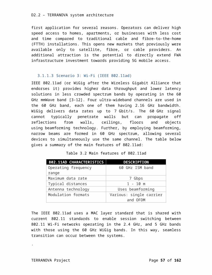
D2.2 – TERRANOVA system architecture
[3-3] Ericsson Microwave Outlook, Trends and Needs in the Microwave Industry, December 2017, © Ericsson AB 2017
[3-4] 5G Backhaul Challenges and Emerging Research Directions: A Survey, May 9, 2016, M. Jaber, M. A. Imran, R. Tafazolli, A. Tukmanov
[3-5] Jafari et al. EURASIP Journal on Wireless Communications and Networking (2015) 2015:206, https://link.springer.com/content/pdf/10.1186/s13638-015-0426-y.pdf
[3-6] SPEED-5G D4.4: Final definition of the RM solution options and recommendations, https://speed-5g.eu/wp-content/uploads/2018/01/speed5g-d4.4_final-definition-of-the-rm-solution-options-and-recommendations-public-version.pdf
[3-7] WiBAS™ OSDR, http://www.intracom-telecom.com/en/products/wireless_network_systems/home_business_access/wibas.htm
[3-8] MultiHaul™ Series, https://www.siklu.com/portfolio-posts/multihaul-point-to-multipoint/
[3-9] airMAX, https://community.ubnt.com/t5/tkb/articleprintpage/tkb-id/airMAX_FAQ/article-id/36
[3-10] P. K. Chartsias, A. Amiras, I. Plevrakis, I. Samaras, K. Katsaros, D. Kritharidis, E. Trouva, I. Angelopoulos, A. Kourtis, M.S. Siddiqui, A. Viñes, E. Escalona, “SDN/NFV-based End to End Network Slicing for 5G Multi-tenant Networks”, 2017 European Conference on Networks and Communications (EuCNC).
[3-11] Delivering 5G mmWave fixed wireless access, David Schnaufer, Bror Peterson, September 28, 2017.
[3-12] 802.11ad WILL VASTLY ENHANCE Wi-Fi, white paper, ABIresearch 2016, Philip Solis and Malik Saadi.
[3-13] IEEE Standard for Ethernet, Amendment 3: Physical Layer Specifications and Management Parameters for 40 Gb/s and 100 Gb/s Operation over Fiber Optic Cables, IEEE Ethernet 802.3bm – 2015.
[3-14] IEEE Standard for Ethernet, Amendment 10: Media Access Control Parameters, Physical Layers, and Management Parameters for 200 Gb/s and 400 Gb/s Operation, IEEE Ethernet 802.3bs – 2017.
[3-15] IEEE Standard for Information technology – Telecommunications and information exchange between systems – local and metropolitain area networks – specific requirements, Part 3: Carrier Sense Multiple Access with Collision Detection (CSMA/CD) Access Method and Physical Layer Specifications, Amendment 1: Physical Layer Specifications and Management Parameters for 10 Gb/s Passive Optical Networks, IEEE EPON 802.3av – 2009.
[3-16] IEEE P802.3ca 100G-EPON Task Force, Physical Layer Specifications and Management Parameters for 25 Gb/s, 50 Gb/s, and 100 Gb/s Passive Optical Networks, IEEE NG-EPON, http://www.ieee802.org/3/ca
[3-17] ITU-T Series G: Transmission systems and media, digital systems and networks, Digital sections and digital line system – Optical line systems for local and access networks, 10-
TERRANOVA Project Page 57 of 117
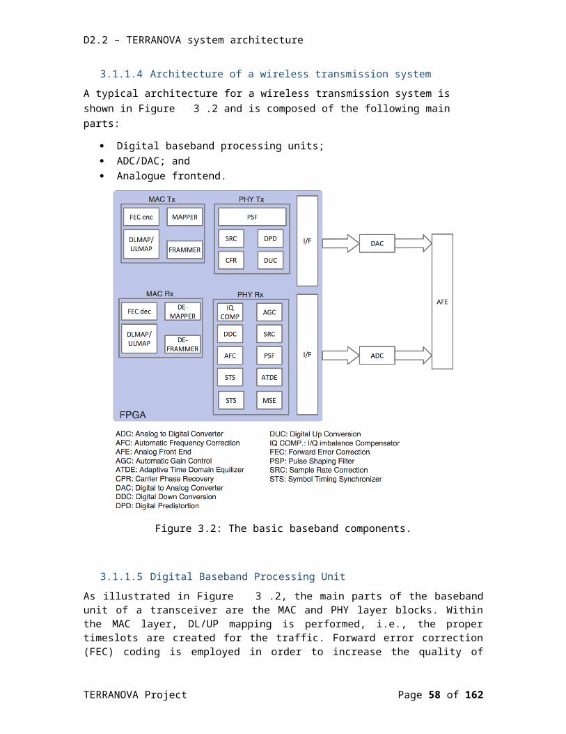
D2.2 – TERRANOVA system architecture
Gigabit-capable passive optical networks (XG-PON): General requirements, G.987.1, 03/2016
[3-18] ITU-T Series G: Transmission systems and media, digital systems and networks, Digital sections and digital line system – Optical line systems for local and access networks, 40-Gigabit-capable passive optical networks (NG-PON2): General requirements, G.989.1, 03/2013, and Amendment 1, 08/2015
[3-19] OIF project website, http://www.oiforum.com/technical-work/current-oif-work/, OIF 400ZR Interoperability
[3-20] 100Gb/s CAUI-10 (10x 10 Gb/s) is defined within IEEE Std 802.3ba-2010, 100 Gb/s CAUI-4 (4x 25 Gb/s) is defined with IEEE Std 802.3bm-2015, 100 Gb/s 100GAUI-2 (2x 50 Gb/s) will be defined within IEEE Std 802.3cd
[3-21] OIF Optical Internetworking Forum, Common Electrical I/O (CEI) - Electrical and Jitter Interoperability agreements for 6G+ bps, 11G+ bps,25G+ bps I/O and 56G+ bps, IA # OIF-CEI-04.0, December 29, 2017.
[3-22] SFF Committee, INF-8077i, 10 Gigabit Small Form Factor Pluggable Module, Revision 4.5, August 31, 2005, http://www.snia.org/sff/specifications.
[3-23] CFP Multi-Source Agreement, http://www.cfp-msa.org.
[3-24] SFF Working Committee, now SNIA Technology Affiliates, http://www.snia.org/sff/specifications.
[3-25] CWDM4 MSA Group, http://www.cwdm4-msa.org/.
[3-26] 100G PSM4 MSA, http://psm4.org/.
[3-27] Ethernet Alliance, The 2016 Ethernet Roadmap, http://ethernetalliance.org/roadmap/
[3-28] Brian Welch, Luxtera, 400G-PSM4: Design and Specification Exercises, http://www.ieee802.org/3/bs/public/14_09/welch_3bs_01b_0914.pdf.
[3-29] SFF Committee, SFF-8679, Specification for QSFP28 4x Base Electrical Specification, Rev 1.7, August 12, 2014, https://doc.xdevs.com/doc/Seagate/SFF-8679.PDF.
[3-30] CFP MSA, CFP4 Hardware Specification, Revision 1.1, 18 Mar 2015, http://www.cfp-msa.org/Documents/CFP-MSA_CFP4_HW-Spec-rev1.1.pdf.
[3-31] CFP MSA, CFP2 Hardware Specification, Revision 1.0, 31 July 2013, http://www.cfp-msa.org/Documents/CFP2_HW-Spec-rev1.0.pdf.
[3-32] CFP MSA, CFP MSA Hardware Specification, Revision 1.4, 7 June 2010, http://www.cfp-msa.org/Documents/CFP-MSA-HW-Spec-rev1-40.pdf.
TERRANOVA Project Page 58 of 117

D2.2 – TERRANOVA system architecture
[3-33] OIF Internetworking Forum, Physical and Link Layer (PLL) Working Group, Implementation Agreement for a CFP2 Analogue Coherent Optics Module, IA OIF-CFP2-ACO-01.0, Jan 22, 2016.
[3-34] OIF Internetworking Forum, Physical and Link Layer (PLL) Working Group, Implementation Agreement for High Bandwidth Integrated Polarization Multiplexed Quadrature Modulators, IA # OIF-HBPMQ-TX-01.0, Jan 19, 2017
[3-35] OIF Internetworking Forum, Physical and Link Layer (PLL) Working Group, Implementation Agreement for Implementation Agreement for Micro Intradyne Coherent Receivers, IA # OIF-DPC-MRX-02.0, June 21, 2017
[3-36] Damian Morero et al., Design Tradeoffs and Challenges in Practical Coherent Optical Transceiver Implementations, Journal of Lightwave Technology, vol. 34, no. 1, pp. 121-136, Jan 2016.
[3-37] Lightwave Online, Press release, “Acacia Communications offers 400-Gbps coherent transceiver module”, http://www.lightwaveonline.com/articles/2015/03/acacia-communications-offers-400-gbps-coherent-transceiver-module.html
[3-38] Lightwave Online, Press release, “Acacia Communications debuts 1.2-Tbps AC1200 coherent optical module”, http://www.lightwaveonline.com/articles/2017/09/acacia-communications-debuts-1-2-tbps-ac1200-coherent-optical-module.html
[3-39] Socionext, Press Release, “Socionext takes part in Record-breaking Transmission Field Trial of 38.4Tbps over 762 kilometers,” [Online] Available https://www.socionext.com/cn/pr/sn_pr20150630_01e.pdf, 30th June 2015
[3-40] R. Elschner et al., “Improving Achievable Information Rates of 64-GBd PDM-64QAM by Nonlinear Transmitter Predistortion”, Optical Fiber Communication conference (OFC) 2018, paper M1C.2.
[3-41] ITU-T Series G: Transmission systems and media, digital systems and networks, Radio-over-fibre (RoF) technologies and their applications, Supplement 55, 07/2015
[3-42] EU Project TERRANOVA (grant agreement 761794), D2.1: TERRANOVA System Requirements, public deliverable, v1.0, December 2017
TERRANOVA Project Page 59 of 117

D2.2 – TERRANOVA system architecture
4.THZ FRONTEND Today’s available THz frontends and their package integration still dramatically differ from mmWave reference systems. When discussing the SOTA of THz frontends one needs to be aware that there is no commercial THz wireless frontend product available as of today. The existing research prototypes need to still adopt many functionalities and features that are considered to be standard functions in microwave or mmWave wireless systems, for example automatic gain control or frontend calibration and impairment correction schemes. The functional integration density is little advanced and it is the great THz frontend development challenge of the next coming years to alter this. Conceptually, mere frequency scaling of proven mmWave frontend architectures is one possible strategy. However, the wireless baseband modem technologies have not evolved in the same way so far. For this reason, there is a significant gap between available modem technology and the possible capacities of the wireless THz channel. There are also technological limitations. With every transition to smaller semiconductor transistor nodes, whatever specific technology one favours, the chip manufacturing process complexity increases and the yield drops.
The development of THz packaging and antenna integration technologies needs to evolve as well. At THz frequencies, quasi-optical antenna solutions actually may shrink to an acceptable size in comparison to implementing them at low millimetre-wave frequencies, for example at 28 GHz. This offers for MIMO, P2MP and beamforming systems new options that need to be taken into account. Solutions that minimize the required number of channels or antenna elements are considered to be disruptive solutions at THz frequencies. The reason is only partly the integration density problem and the associated limitations of implementing larger active antenna arrays. Another important aspect is the energy efficiency requirement especially for mobile battery driven UE.
TERRANOVA follows a strategy other than mere frequency scaling though not in a dogmatic sense. Where frequency scaling is applicable, it should be used. The motivation is rather the pragmatic idea to exploit the progress of optical fibre transceiver technologies and the fibre optical infrastructure, technically and economically. The technical benefits are the available tremendous baseband capacity, circumventing today’s wireless modem performance bottleneck and complementing fibre optical networks. The economic charm is the access to available inexpensive and very advanced baseband ASICs and the ease to introduce modified DSP algorithms.
The electrical “baseband” interface of most common optical communication systems today and in future actually influences the frontend architectures in this scenario. For example, the baseband signal format determines the bandwidth or frequency plan, the number of channels and possible duplexing solutions of the wireless link. Vice versa, the available frontend capabilities partly determine if an optical DSP is required at the interface between the optical and THz wireless link and in that sense the design process attains the nature of a co-design. There are numerous frontend options suddenly to choose among and part of this chapter aims to summarize the major ones. The problem is also strongly related to multiplexing methods and
TERRANOVA Project Page 60 of 117

D2.2 – TERRANOVA system architecture
in some way time domain and frequency domain multiplexing plays an important role in the interface.
Overall, it is one of the major challenges and targets of WP5 to analyze and develop the building blocks of the TERRANOVA media converter. This media converter has to perform a mapping between the different optical transmission standards and the THz frontend including the THz antenna. Having an optical DSP available in that media converter offers the most flexibility to modify signal formats (modulation, symbol rates, bandwidth efficiency) but increases also the complexity.
Section 4 follows a similar structure as the previous sections. Based on typical reference solutions, in this section, we define what, in this project, is considered to be SOTA as a starting point for new research and innovation actions. Since there are no commercial THz frontend products available, commercial industrial scientific and medical (ISM)-60 GHz (57-64 GHz) and E-band (71-76 GHz, 81-86 GHz) radio frontends are discussed for this purpose. The latest 5G prototypes are used to derive the SOTA in mmWave beamforming frontend arrays. In the next steps, the chapter summarizes the fundamental frontend bandwidth and capacity limits at different THz transmission windows, followed by baseband interface solutions and available technologies. The section concludes with the revision of some THz antenna solutions and BF frontend architectures to be considered as potentially disruptive technologies.
4.1 Reference components/technologies This section presents the state-of-the-art of commercially available RF frontends and the key chipsets using a few selected widespread examples. The focus is on ISM-60 GHz and E-band radio links for P2P applications. In addition, there are several proprietary frontend solutions developed by telecom infrastructure vendors which will be not covered. Beamforming frontends for 60 GHz wireless gigabit alliance (WiGig) and upcoming 5G-NG are discussed next. It is also interesting to compare the typical technical specifications of commercial ISM band in 60 GHz and E-band frontends with a first-generation research prototype for THz links.
4.1.1 ISM-60 GHz frontendsThe frequency spectrum around 60 GHz is characterized by an atmospheric loss maximum due to oxygen absorption. For this reason, the ISM-60 GHz (57-64 GHz) band is mostly used for small cell and indoor applications. Although beamforming solutions are becoming increasingly popular the frontend solution based on the HMC6300/HMC6301 chipset from Analogue Devices is chosen as a reference design for typical 60 GHz applications. The main reason is that there are well documented evaluation kits and reference designs available, which include modem implementations based on XILINX’s Kintex®-7 field-programmable gate array (FPGA) series. This is very attractive for short time-to-market designs and explains the widespread use of this platform.
The HMC6300/HMC6301 is a two chip RX and TX solution and it is the second generation silicon-germanium (SiGe) technology based chipset release of Analogue Devices for the 60 GHz frequency band. The block diagram of Figure 4.12 gives an overview of the frontend and the interface to XILINX’s FPGA based modem, as suggested by the reference design of [4-1]. While the Analogue Devices HMC6000/HMC6001 frontend chipset integrates an antenna-in-package
TERRANOVA Project Page 61 of 117
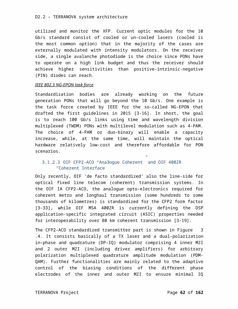
D2.2 – TERRANOVA system architecture
(AiP) this solution offers an RF board I/O. An off-board diplexer can be used to realize full-duplex using different carrier frequencies (i.e., FDD). Alternatively, the chipset also supports TDD operation. The HMC630x and HMC600x are also an example for the pros and cons of AiPs. AiPs are very attractive for consumer end products. For application prototyping, however, it is often asked to have the opportunity to explore different frequency bands and duplex operation, being not limited by a very specific antenna implementation.
Figure 4.12: Typical frontend architecture at 60 GHz based on Analog Devices HMC6300/HMC6301 chipset [4-1].
The block diagrams of the transmitter and receiver architecture are shown in Figure 4.13, taken from [4-1]. The chips are packaged in a wafer level ball grid array (WLBGA) compatible to standard surface mount technologies on PCBs (printed circuit board). The frontend becomes quite simple due to the integration levels of the RX/TX chips. For example, the chips integrate a voltage controlled oscillator (VCO), which is stabilized by an on-chip phased locked loop (PLL), reducing the external component count. The reference LO frequency can be adjusted between 16.3 GHz and 18.3 GHz. In order to operate at higher order modulation schemes (> 64-QAM) an external VCO can be used. The phase noise of the internal PLL-stabilized VCO is sufficient for modulation schemes up to 64-QAM. The chip also includes variable gain amplifiers, located at the transmitter side in the RF stages and at the receiver side in the baseband. All functions are controlled via a Serial Peripheral Interface (SPI). The carrier frequency can be selected via SPI programming interface for FDD operation and for adjusting to different international 60 GHz frequency spectrum regulations.
Analogue quadrature modulation and demodulation is properly the most widespread transceiver architecture for mmWave radios. The HMC6300/HMC6301 use an intermediate carrier frequency (ICF) between 8 GHz and 9.1 GHz. The complex modulated carrier is then frequency converted using 3x the reference LO frequency. Image rejection is achieved by an on-
TERRANOVA Project Page 62 of 117
D2.2 – TERRANOVA system architecture
chip 40-46 GHz band stop filter. The I, Q baseband signals and the RF signals are differential signals. Unless differential antennas are used an external balun is required on the PCB.
The photograph of Figure 4.14, taken from [4-1], shows a prototype link for lab tests according to the block diagram of Figure 4.12. The diplexer is omitted in this setup.
(a)
(b)
Figure 4.13: ISM-60 GHz frontend RX/TX chipset (HMC6300/HMC6301) from Analogue Devices [4-1], (a) Tx chip, (b) Rx chip.
TERRANOVA Project Page 63 of 117

D2.2 – TERRANOVA system architecture
Figure 4.14: Implementation of the 60 GHz reference frontend (HMC6300/6301 chipset) in a test link [4-1].
The typical technical key parameters of the ISM-60 GHz frontend reference chipset are summarized in Table 4.5 for the transmitter and receiver chip.
Table 4.5: Technical key parameters of the ISM-60 GHz frontend reference [4-2], [4-3].
Analog Devices HMC6300 / HMC6301 chipset
Frequency band: 57 GHz to 64 GHzRF signal bandwidth: up to 1.8 GHz (3% rel.)
Transmitter: Output power for 1 dB compression: 15 dBm, Psat = 17 dBm (balanced)
Receiver: Noise figure at maximum gain, typ. 8 dB, max. 13.5 dB
Architecture: IF IQ modulator and single sideband up/down-converterUniversal analog I/Q baseband interface
Local oscillator:Integrated synthesizer to support up to 64 QAM modulationTypical phase noise performance:
@ 100 kHz Offset −75 dBc/Hz@ 1 MHz Offset −93 dBc/Hz@ 10 MHz Offset −114 dBc/Hz@ 100 MHz Offset −122 dBc/Hz
External LO injection option for modulation schemes up to 256 QAM
Power dissipation: 1 W (balanced), 0.88 W (single-ended)
TERRANOVA Project Page 64 of 117

D2.2 – TERRANOVA system architecture
0.75 W (balanced, external LO)
Additional features:Digital and analog RF and intermediate frequency (IF) gain control featuresIntegrated AM and FM detectors3-wire serial digital interfaceOn-chip temperature sensor
Packaging:65-ball, 4.00 x 6.00 mm, wafer level ball grid array, surface mountable
4.1.2 E-band frontendsFrontends based on Infineon’s commercially available BGT70 / BGT80 chipset are probably one of the most widespread solutions for wireless P2P radio links at E-band [4-4], [4-5]. An ecosystem of application notes, evaluation boards and modem solutions is available in addition which makes the use of this frontend platform very attractive. Since it is a rather complete platform for the development of wireless P2P links it is chosen as a reference frontend on which major standard capabilities are discussed. The BGT70/BGT80 chipset has been developed in Infineon’s advanced SiGe transistor technology with a transit frequency fT of 200 GHz suitable for addressing high volume markets, packaged in a surface mountable embedded wafer level ball grid array (eWLB). Both chips integrate a full transceiver function with RX and TX, which can be used to realize uplink and downlink operation and the implementation of a full duplex system in FDD using the subbands 71-76 GHz and 81-86 GHz. In contrast, there has been not yet a full duplex system demonstrated at THz frequencies and neither is there a standardized surface mount compatible packaging technology available, for example.
The block diagram of the frontend reference design for the BGT70/BGT80, as recommended in [4-4], [4-5], is shown in Figure 4.15. It is neither a single chip frontend nor a single semiconductor technology frontend. Gallium arsenide (GaAs) low noise amplifiers and power amplifiers are added to enhance the link budget for long-range P2P applications. All components are integrated on a printed circuit board (PCB), which is also the interconnect board at the mmWave frequencies, suitable for cost-efficient mass manufacturing. The BGT70/BGT80 have each an internal VCO, which requires an external PLL for stabilization. An external passive waveguide diplexer is used to multiplex the two designated frequency bands, 71-76 GHz and 81-86 GHz between the RF module and the antenna. The E-band reference implementation uses a standard waveguide interface to the antenna. This offers more flexibility to customize the feed antenna and high gain antenna system independent of the frontend to be able to cover a greater variety of application scenarios.
The analogue baseband interface adds additional functions. The main tasks covered in the block diagram are IQ calibration and adjusting the signal levels by variable gain amplifiers (VGAs). IQ calibration is mainly applied to minimize the LO in the transmitter output signal which is a result of unwanted LO feed-through at the IQ mixer. The signal levels need to be adjusted to exploit
TERRANOVA Project Page 65 of 117

D2.2 – TERRANOVA system architecture
the maximum dynamic range and achieve the best SNR. All functions are controlled by an SPI bus, including the functions of the frontend chipset (for example, bias voltages, up/downlink selection, built-in-self test).
The BGT70/BGT80 chipset uses the direct conversion transmitter and receiver architecture, avoiding the additional mixer and image rejection filter that was encountered in the ISM-60 GHz reference design example. The simplified chip architecture comes at the expense of the required IQ calibration for improving the carrier suppression and minimizing the IQ imbalances. More related details on the direct conversion architecture similar to the one used in the BGT70/BGT80 can be found for example in [4-6].
Figure 4.15: Typical frontend architecture at E-band based on Infineon’s BGT70/BGT80 chipset [4-4].
The implementation in Figure 4.16 provides another insight of the typically encountered technologies and features. The PCB-to-waveguide transition is integrated in the PCB, whereas the diplexer is part of the housing of the PCB. Different board materials are in use for the RF frontend part and the host motherboard. Low-cost FR4 board materials can be used for the narrow bandwidths at baseband typically encountered (less than 5 GHz), while the interconnection board for the RF frontend uses lower loss board materials like Rogers’ RO3003 material for example.
TERRANOVA Project Page 66 of 117
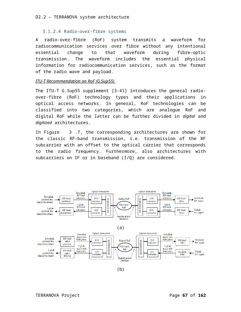
D2.2 – TERRANOVA system architecture
Figure 4.16: Implementation of the E-band reference frontend based on Infineon’s BGT70/BGT80 chipset [4-5].
The typical technical key parameters of the E-band frontend reference chipset are summarized in Table 4.6 for the transmitter and receiver chip. Please note that the noise figure of the total frontend with GaAs based reference low-noise and power amplifiers are higher.
Table 4.6: Technical key parameters of the E-band frontend reference [4-5], [4-6].
Infineon BGT70/BGT80 chipset and frontend
Frequency band: 71-76 GHz, 81-86 GHzRF signal bandwidth: (supported channel bandwidth) 50 MHz to 1 GHz (1% rel.)
Transmitter BGT80: BGT80: Psat = 9.2 dBfrontend incl. GaAs PA: Psat = 21 dBm, typ 12 dBm @ 64 QAM
Receiver: BGT80: noise figure of better than 11 dB (81-86 GHz)Frontend incl GaAs LNA: 8 dB at antenna portFrontend diplexer insertion loss: < 0.7 dB
Architecture: Zero IF – differential I/Q interface – direct conversion architecture
Tx I/Q amplitude / phase imbalance 0.5 dB / 8 degRx I/Q amplitude / phase imbalance 1 dB / 7 deg
Local oscillator:Built in VCO with external PLL, to support up to 64 QAM modulationTypical phase noise performance:
@ 100 kHz Offset −83 dBc/Hz@ 1 MHz Offset −105 dBc/Hz@ 10 MHz Offset −126 dBc/Hz
Power dissipation: 1.5 W (BGT Tx)
TERRANOVA Project Page 67 of 117

D2.2 – TERRANOVA system architecture
1.2 W (BGT Rx)4.8 W (GaAs PA)
Additional features:Built-in-test equipment for self-test and calibration in production SPI programming interfaceOn-chip temperature sensor
Packaging:119-ball, 6.0 x 6.0 mm, embedded wafer level ball-grid array (eWLB) package
4.1.3 First generation THz frontend research prototypesNowadays, there are no THz frontends commercially available above 200 GHz. For this reason, one of the first published monolithically integrated and packaged research prototype chipsets is used as a reference [4-8]. This chipset was developed and investigated between 2012 and 2015 by the Fraunhofer IAF, and operates over the frequency band from 275-325 GHz. In a laboratory environment, wireless transmission at data rates up to 64 Gbit/s was verified using QPSK modulation. The achieved date rates were limited by the available test equipment and baseband signal processing capabilities.
The block diagram of the reference design for a typical P2P test link is shown in Figure 4.17. The M170M03H is a multifunctional front-end module using the Fraunhofer IAF 35 nm InAlAs/InGaAs HEMT (high electron mobility transistor) MMIC technology with a maximum oscillation frequency of more than 1 THz. The LO reference signal of the M170M03H-TX/RX modules is provided by the M185X12W at an input frequency of 100 GHz, which is then internally multiplied-by-3. The M185X12W is a one-chip fully integrated multiplier-by-12. The local oscillator frequency can be adjusted over a wider range between 285-315 GHz. The 300 GHz front-end MMIC of the M170M03H-TX/RX implement a quadrature direct-conversion architecture with single-ended IF, LO and RF connections. In detail, the Rx and Tx MMIC integrate on a single chip several functions: broadband IQ-mixer, frequency tripler, buffer amplifier, and broadband low-noise amplifier (RX), respectively medium power amplifier (TX). The multifunctional MMIC is packaged in a split-block module with a WR-3 waveguide interface. Both modules, the TX (M170M03-TX) and the RX (M170M03-RX), have the same dimensions and connector types.
TERRANOVA Project Page 68 of 117
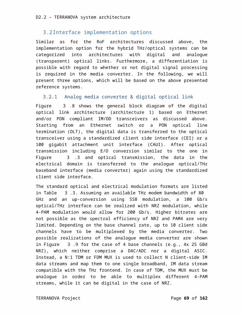
D2.2 – TERRANOVA system architecture
Figure 4.17: Research prototype frontend for the 275-325 GHz band based on the Fraunhofer IAF chipset.
In comparison to previous examples at 60 GHz and E-band, no analog baseband interface with variable gain amplifiers exist, and broadband baseband amplifiers are realized off-chip. The actual physical implementation of the frontend is shown in Figure 4.18 and Figure 4.19. The split block modules include a microcontroller for programming the bias supply “at factory” to guarantee optimum performance although there is no in-operation configuration or adjustment possible. The approximate module sizes are 35 x 30 x 20 mm for both modules. All baseband and RF signals are single-ended, provided to the modules using a 1.85 mm coaxial V-connector.
Figure 4.18: Fraunhofer IAF’s M170M03H frontend with Rx respectively Tx chip for the 275-325 GHz band.
Figure 4.19: Fraunhofer IAF’s M185X12W multiplier-by-12 module for generating the LO at 100 GHz.
A typical lab setup for the transmission experiments up to 64 Gbps is shown in Figure 4.20. No full-duplex operation has been tested so far. For emulating the FSPL, a 300 GHz broadband waveguide attenuator in front of the 20 dBi horn antenna is used at the transmitter side. RX and
TERRANOVA Project Page 69 of 117

D2.2 – TERRANOVA system architecture
TX can be pre-synchronized using a manual phase shifter, while the carrier estimation is performed using DSP at the baseband.
Figure 4.20: Fraunhofer IAF’s M185X12W multiplier-by-12 module for generating the LO at 100 GHz.
The typical technical key parameters of the THz frontend reference chipset are summarized in Table 4.7. The performance was measured at module level with respect to the waveguide and coaxial interface. The listed power consumption of the M170M03H is lower since it has no integrated broadband baseband amplifiers. The typical power consumption is approximately 200 mW for the I and Q channel each.
Table 4.7: Technical key parameters of the THz frontend reference.
Fraunhofer IAF’s M170M03H-TX/RX frontend modules
Frequency band: 275-325 GHzRF signal bandwidth: (supported channel bandwidth) 50 GHz (16% rel).
Transmitter:Psat = 0 dBm, typ. -8 dBm @ 4-16 QAM
Receiver: Noise figure of better than 10 dB (275-325 GHz)Receiver sensitivity better than -50 dBm
Architecture: Zero IF – single-ended I/Q interface – direct conversion architecture
I/Q amplitude / phase imbalance 1 dB / 1 deg
TERRANOVA Project Page 70 of 117

D2.2 – TERRANOVA system architecture
Local oscillator:External local oscillator injection at 8.333 GHz.Typical phase noise performance (at 300 GHz) for DDS generated LO injection signal:
@ 100 kHz Offset −85 dBc/Hz@ 1 MHz Offset −90 dBc/Hz@ 10 MHz Offset −100 dBc/Hz@ 100 MHz Offset < -105 dBc/Hz
Power dissipation: (excluding external baseband amplifiers)0.45 W (M170M03H-TX/RX)1.1 W (M185X12W)0.4 W (IQ baseband amplifiers)
Additional features:Module integrated microcontroller for biasing
Packaging:Waveguide split-block package, typ. size of a module 35 x 30 x 20 mm
4.1.4 Beamforming frontends for 5G, 60 GHz WiGig and 300 GHz THz links
The state-of-the-art is defined on the example of beamforming frontends for two important mmWave phased array communication applications. Phased array frontends for ISM-60 GHz have been developed for more than 10 years [4-9]. Today, this work has become a commercially available reality, for example for indoor wireless transmission at Gbps data rates or for backhaul applications [4-10]. Phased array communication frontends are also evolving for 5G New Radio (NR) at 28 GHz [4-11]. Currently, there is a lot of proprietary 5G development work in progress by telecom infrastructure vendors in collaboration with chip manufacturers. A research prototype is chosen to define the SOTA within those activities.
No commercial THz phased array communication system exists so far and the SOTA is defined by a research prototype instead at the end of this section. The different general beamforming options will be discussed in Section 4.3.
4.1.4.1 ISM-60 GHz beamforming frontend [4-9], [4-10]Indoor wireless media streaming at Gbps data rates was one of the main drivers for the development of phased array communication systems at the ISM-60 GHz band. Both digital baseband PHY/MAC and RF chips were developed to end at a very small form factor of the complete system suitable for UE markets. This application advanced the state-of-the-art of RF frontend and antenna-in-package integration drastically. The first chipset that was commercially available from SiBeam, shown in Figure 4.21, had 32 TX and 4 RX channels integrated on a single
TERRANOVA Project Page 71 of 117
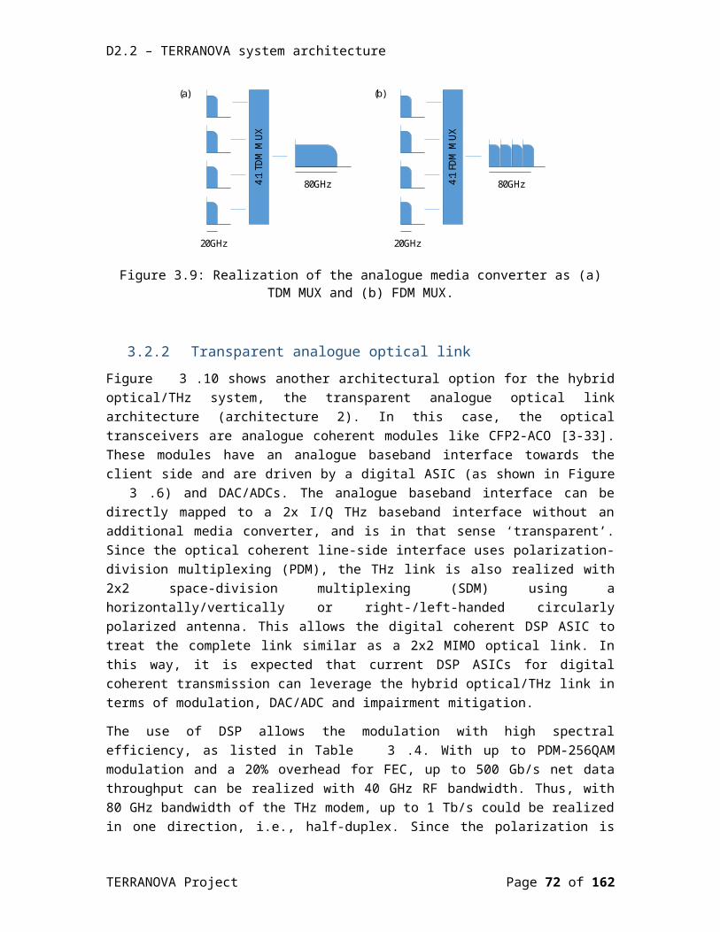
D2.2 – TERRANOVA system architecture
chip in 90 nm complementary metal–oxide–semiconductor (CMOS). An analogue RF beamforming architecture was used, and the resulting chip size was approximately 8 x 8 mm.
Figure 4.21: SiBeam’s 60 GHz chipset, presented in 2008.
4.1.4.2 5G-NR beamforming frontend at 28 GHz [4-12]Beamforming systems at 28 GHz follow similar architectural paradigms as the first 60 GHz phased array communication frontends demonstrated; mostly RF beamforming architectures are encountered. In comparison to 60 GHz data streaming / broadcasting applications, 5G applications expect a FD symmetric operation. For that reason, IBM / Ericsson propose a 64 element dual polarized antenna array which is defined as the state-of-the-art in upcoming 28 GHz 5G-NR applications. Four 2x16 channel transceiver monolithic microwave integrated circuits (MMICs) are used to drive the antenna. The chip size is 10.5 x 15.8 mm. The frontend transceiver chip is depicted in Figure 4.22 and the implementation of the antennal is shown in Figure 4.23 [4-12], [4-13].
TERRANOVA Project Page 72 of 117
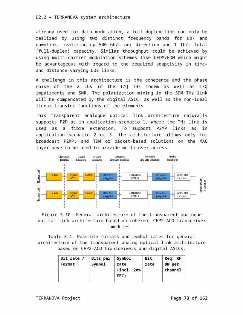
D2.2 – TERRANOVA system architecture
Figure 4.22: IBM / Ericsson’s 5G beamforming transceiver chipset [4-12].
Figure 4.23: Implementation of the 5G 28 GHz beamforming antenna by IBM / Ericsson [4-13].
The frontend has a power consumption of 4.6 W per polarization / per chip for the 16 transmitters and 3.3 W per polarization / chip for the 16 receivers, resulting in a total power consumption of 15.8 W per transceiver chip or approximately 60 W for a 64 element Tx/Rx antenna, or approximately 1 W per transceiver antenna element.
4.1.4.3 THz phased array communications prototype at 300 GHz [4-14]The integration of wireless THz frontends is currently limited by the functional integration density. In theory, the chipsets should become smaller at THz frequencies. However, due to the increasing FSPL with increasing frequency, the phased array antenna gain has to also increase. This results in a prohibitively large number of array elements, which cannot be realized at THz frequencies today. It also means that the chips are effectively not becoming smaller than for example at ISM-60 GHz. One of the future key research topics will be to minimize the required number of active antenna elements for this reason. The direct current (DC) power consumption is a further important motivation to reduce the number of active elements; obviously a power
TERRANOVA Project Page 73 of 117

D2.2 – TERRANOVA system architecture
consumption of 60 W per antenna is for many UE applications not acceptable. The power consumption per amplifier is reduced at THz frequencies in comparison to 28 GHz for example, but only due to the lower output power levels which need to be compensated by more active antenna elements. For this reason, it is still an overall very high power consumption expected for a THz beamforming array.
A research prototype at the Fraunhofer IAF for testing beamforming at 300 GHz is shown in Figure 4.24. Although this is not an integrated solution at all, it is considered as the state-of-the-art for testing 300 GHz phased array communications today. The frontend architecture uses phase shifting in the LO path. A full transmitter respectively receiver is used behind each antenna element making the platform also attractive to test MIMO schemes. The modular concept allows a modification of the antenna for testing different scenarios quite easily. The testbed was used up to now for testing modulation formats up to 32-QAM at 4 Gbaud, limited by the available test equipment for signal generation and analysis. Another important aspect is the differential phase stability, which must be considered for MIMO solutions. In contrast, RF beamforming installs only one common local oscillator for all antenna elements.
a)
(b)
Figure 4.24: Fraunhofer IAF’s testbed for phased array communications at 300 GHz using the M170M03H-TX/RX frontend modules [4-14]: (a) photograph of the Tx frontend, (b) block
diagram of the setup.
TERRANOVA Project Page 74 of 117
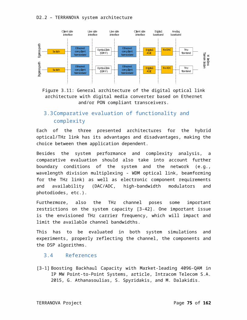
D2.2 – TERRANOVA system architecture
4.2 Baseband up/down-conversion subsystemThe previous sections have summarized typical standard transceiver architectures encountered at millimetre-wave frequencies, and compared them to a currently available THz solution. The comparison revealed that a quite significant functional gap has to be closed between the millimetre-wave and THz frontends. The TERRANOVA media-converter dictates additional boundary conditions and specifications.
The basic function of the TERRANOVA frontend and TERRANOVA media-converters under discussion is the mapping between a number of modulated optical carriers and a number of modulated electrical THz carriers. A generic solution needs to be found which is applicable to different fibre optical standards. In this section the main options from section 3 are discussed from the perspective of the THz frontend. Figure 4.25 gives a very generic overview of the required functions for introducing a common terminology in this section. From the optical to the THz wireless media, the modulated optical carrier is demodulated and in that process also an electro-optical conversion takes place. The signal mapping is typically implemented in the electrical domain and can be an analogue time or frequency multiplexing operation, for example. The new signal format modulates one or more electrical carriers. From the THz wireless media to the optical media, the functions are reversed.
Figure 4.25: Generic Functions of the TERRANOVA media-converter
There are some aspects that should be highlighted first. The signal mapping can be a linear or nonlinear operation. In a simple transparent case, the demodulated signals are just forwarded to the modulator with optional level shifting. In this case, the symbol rate is maintained and bandwidth requirements are rather dictated by the optical link. The spectral efficiency cannot be changed, and for that reason it is important to work with higher order modulation schemes in the optical domain. If there is a digital signal processing function available for signal mapping, then the symbol rate and modulation format can be changed almost arbitrarily on the expense of losing the “transparency”. Signal mapping can also occur by an analog operation, as mentioned above for example by multiplexing in the time or frequency domain.
The electrical demodulation is one of the most critical functions to be focused on since it requires an accurate estimation of the carrier frequency and phase. Modern millimeter-wave modems implement this function in the Rx PHY. In the transparent analog optical link and the digital optical link with DSP this must be part of the optical digital ASIC. The proper algorithms need to be further developed and tested. A special case is the digital optical link with a DSP-less
TERRANOVA Project Page 75 of 117
D2.2 – TERRANOVA system architecture
media converter (“analog media converter”). Here, analog functions for coherent demodulation need to be developed and implemented, which are often limited to a rather specific set of modulation schemes. Classical carrier recovery solutions either based on frequency doubling or Costas loops are possible candidates. All of those analog approaches have in common to drastically increase the complexity of the THz frontend.
4.2.1 Available technologiesThe quadrature modulator is the most common and flexible architecture in modern wireless communication systems. There are occasions were simplified amplitude modulation (AM) or frequency modulation (FM) architectures can be used, but mostly on the expense of limited spectral efficiency and data rates. For example, very simple on-off-keying (OOK) does not require the generation of IQ components and non-coherent envelope detection can be used. This resembles the IM/DD system architectures of optical systems with all the required functionalities. Some of the commercial off-the-shelf (COTS) integrated circuits may be applied to the THz wireless demodulation.
The quadrature modulator generates the in-phase and quadrature complex signal components in the baseband, and an IQ mixer generates the modulated carrier out of those signal components. In that way amplitude and phase can be modulated most generally at the same time leading to a high spectral efficiency. The modulated carrier can be at the RF transmit frequency (direct conversion) or at an IF. Both IQ-modulation architectures are found at millimetre-wave frequencies, e.g. the E-band reference design based on the BGT70/BGT80 chipset uses a direct conversion approach, while the ISM-60 GHz reference design based on the HCM6300/6301 uses an intermediate carrier frequency for the IQ carrier modulation. At THz frequencies, the direct conversion architecture was implemented and experimentally tested at the Fraunhofer IAF and it was shown that a bandwidth of 40 GHz can be realized at the baseband which results in an 80 GHz RF bandwidth.
There is an interesting option of the quadrature modulator to be further investigated in the course of this project. The progress of modern wideband ADC/DAC frontends for optical communication systems renders also the implementation of all-digital IQ modulation architectures at an intermediate carrier frequency feasible. Most of the IQ-imperfections found in analogue IQ modulators can be easily eliminated with this approach. The hardware complexity shifts to the development of fast ADC/DAC frontends which need to be calibrated by DSP.
The major options for IQ modulation and up-conversion in TERRANOVA are listed in Figure 4.26.
TERRANOVA Project Page 76 of 117

D2.2 – TERRANOVA system architecture
Figure 4.26: Major options for IQ modulation and up-conversion
The corresponding down-conversion and demodulation resemble those cases. Filter blocks were neglected in the schematics for simplification of the drawings. The generation of the LO signals, which provide the carrier signal for modulation, or the frequency-translating signal for up-conversion, are generated by cascaded frequency multipliers. All LOs are derived from a common reference signal source. Synchronous demodulation requires that the LO for demodulation corresponds to the carrier frequency, having the same phase.
4.2.2 Implementation optionsThe different frontend options for the hybrid THz/optical, as discussed in Section 3.2, are summarized in Table 4.8. The important key parameters are the required bandwidth, the modulation scheme and the number of channels respectively the implementation of the duplex operation.
The IQ modulation schemes are limited to 128 QAM by the current receiver, whereas 64 QAM is the preferred to guarantee sufficient margin. The digital media converter allows the most flexible mapping of modulation schemes and bandwidths. For the coherent optical links, 2 IQ- channels exist at the baseband that will be mapped to two polarizations.
Full-duplex operation can be implemented by space division duplexing (SDD) using two different polarizations or by frequency division duplexing (FDD) using two different frequency bands. In addition, time division duplexing (TDD) is a viable option for P2MP scenarios but requires
TERRANOVA Project Page 77 of 117

D2.2 – TERRANOVA system architecture
additional synchronization overhead. Since the polarizations will be used to map the two optical polarizations, FDD is the remaining option for full-duplex operation.
The early THz prototypes at 300 GHz carrier frequency showed that a bandwidth of 40 GHz at baseband can be realized which results in an RF bandwidth of 80 GHz for IQ modulation or DSB (double sideband) modulation. For a single sideband (SSB) modulation, about 40 GHz RF bandwidth seems to be feasible, extrapolating from existing AM-OOK prototypes at 80 GHz. A more realistic frequency plan would target a frequency window from 220 – 300 GHz to exploit the full bandwidth capabilities of the frontend and the atmospheric absorption window. In case of FDD, the definition of a guard band of 10 – 20 GHz for passive waveguide diplexers is required and must be further investigated by test designs. This would lead to a FDD scheme with a down-channel from 210 – 250 GHz and an up-channel from 260 – 300 GHz for example.
Table 4.8: Frontend architectures for hybrid THz/optical links.
Digital optical link - analogue media converter – non-coherent opticalRx: Analogue carrier phase recoveryOptical modulation: IM/DD (NRZ / PAMx) <-> electrical modulation: AM or IQChannels: H/V-pol for duplex, 2x RF channels with 40 GHz bandwidth
Digital optical link – digital media converter – coherent opticalRx: Digital carrier phase recoveryOptical modulation: 16/64/128/256 QAM <-> electrical modulation: 16/64/128 QAMChannels: H/V-pol for optical polarizations, 2x RF channels with 40 GHz bandwidth
Analogue transparent optical link – analogue media converter – coherent opticalRx: Digital carrier phase recovery, remote at optical modemOptical modulation: 16/64 QAM <-> electrical modulation: 16/64 QAMChannels: H/V-pol for optical polarizations, 2x RF channels with 40 GHz bandwidth
4.2.3 Evaluation of functionality and complexityThe successful implementation of IQ quadrature modulation architectures depends on the capability to calibrate and correct IQ impairments at the transceiver. The additional complexity of the implementation for correction schemes is a major decision on the final THz frontend architecture. From this point of view, the IQ digital heterodyne conversion frontend is the most attractive approach, requesting research in new ADC/DAC frontends as part of the media converter. The analogue IQ direct or heterodyne options will benefit from auxiliary calibration receivers. In conjunction with the DSP, it has to be explored to what extend such additional hardware functions will actually translate in improved performance.
Arriving at realistic frontend specifications and selection criteria requires a combination of “paper designs” with realistic transistor process models and actual manufacturing of promising candidates. The actual manufacturing provides valuable insight in performance deviations due to further imperfections hard to quantify only by simulations, e.g. introduced by packaging or the antenna-chip interface.
TERRANOVA Project Page 78 of 117
D2.2 – TERRANOVA system architecture
4.3 Beamforming subsystemReference designs for millimetre-wave beamforming frontends at 28 GHz and ISM-60 GHz were presented at the beginning of Chapter 4. A general classification of different beamforming options is summarized within the following subsections.
4.3.1 Implementation optionsBeamforming techniques can be classified in two main categories, namely, digital and analogue techniques [4-15]. Digital beamforming is applied to the digital baseband signal [4-15], [4-16]. Particularly, in the case in which beamforming is implemented at the transmitter, the samples are multiplied by the beamforming coefficients, before they enter the DAC, whereas in the case of the receive beamforming, the received baseband equivalent signal samples are multiplied with the beamforming coefficients, after the ADC. As it is depicted in Figure 4.27, in the case of transmit beamforming, each array element is driven by a dedicated RF chain.
Figure 4.27: Digital beamforming at the transmitter.
On the other hand, analogue beamforming is applied on the analogue signal, either at the baseband or more usually at the RF (after the upconverter) stage, by employing phase shifters and/or variable gain amplifiers [4-15], [4-16]. In this case, as illustrated in Figure 4.28, only one RF chain is needed.
TERRANOVA Project Page 79 of 117
D2.2 – TERRANOVA system architecture
Figure 4.28: Analogue RF beamforming at the transmitter.
Digital beamforming outperforms the corresponding analogue beamforming. Moreover, it offers more DoF, while, at the same time, it enables multi-stream transmissions. However, as the number of array elements increases, the hardware complexity and the energy consumption become prohibitive, since each antenna requires a dedicated RF-chain [4-15], [4-17]. On the contrary, analogue beamforming is a more practical technique (only one RF-chain is required), but less flexible [4-15], [4-16].
Therefore, the most promising beamforming techniques for future mmWave and THz communication systems involve the combination of both digital and analogue techniques, i.e., the so called hybrid beamforming [4-15], [4-16], [4-18], [4-19] since it offers a good trade-off between performance and complexity. A hybrid beamforming scheme requires a limited number of RF-chains (for the digital part of the beamforming), which is significantly smaller than the number of the antenna elements. Every RF chain drives each one of the antenna elements (fully connected design), through an analogue phase shifter (i.e., a phase shifter is required for every RF chain - antenna element connection) [4-16], [4-18], [4-19]. However, this fully connected structure leads to increased power consumption and implementation cost. Alternative hybrid beamforming designs have been developed, in order to reduce complexity and power consumption. One of the most popular is the array of subarrays is illustrated in Figure 4.29 [4-18], [4-19], where multiple array elements are combined into subarray modules. Each element within a subarray has a phase shift applied directly in the RF domain, while digital beamforming techniques are applied on the signals that feed each subarray. The smaller number of TX/RX chains leads to more efficient beamforming schemes, while performance is maintained at acceptable levels.
Finally, it is important to note that beamforming can be fixed or adaptive [4-15]. In the former, the beamforming coefficients are assumed to be constant, while in the latter, they are calculated dynamically by using sophisticated signal processing algorithms, offering the capability to adapt the beam direction, in real time. Adaptive beamforming is necessary, for instance, when the devices are moving.
TERRANOVA Project Page 80 of 117

D2.2 – TERRANOVA system architecture
Figure 4.29: Hybrid beamforming at the transmitter - array of subarrays.
4.3.2 Evaluation/comparisonDigital beamforming, compared to the other techniques, results to better performance and offers more degrees of freedom, while it can also enable multi-stream transmission. However, as the number of array elements increases, the hardware complexity becomes prohibitive, since each antenna requires a dedicated RF-chain. Analogue beamforming, on the contrary, is a more practical technique (only one RF-chain is required), but less flexible [4-15], [4-16].
The most promising technique for future THz communication systems is hybrid beamforming, since it offers a good trade-off between performance and complexity.
4.4 THz antenna optionsThe antenna options for the three different use-case scenarios of TERRANOVA, P2P (point-to-point), P2MP (point-to-multi-point) and indoor quasi directional (IQD) differ in their requirements on antenna beam forming, reconfiguration and directivity. Classical beamforming antenna arrays are certainly the most challenging antennas for a THz frontend since they require complex beamforming networks. The previous section has introduced the basic available beamforming network options to be further investigated for that purpose. This section is mainly focused on the quasi-optical antenna solutions for the three use case scenarios of TERRANOVA. It is important to consider that quasi-optical antenna solutions may shrink to an acceptable size
TERRANOVA Project Page 81 of 117
D2.2 – TERRANOVA system architecture
in comparison to implementing them at low mmWave frequencies. This offers new options for reducing the complexity of adaptive or reconfigurable high gain antenna arrays. Within this project, available manufacturing technologies and future low cost solutions need to be taken into account as well. The advent of 3D printing, precision metal injection moulding, and chemical micromachining technologies provides possibilities for an innovative antenna feed system design, suitable for the dimensions at THz frequencies> 100 GHz.
In essence, when talking on the merits of quasi-optical antennas for THz communications, three possible design targets can be identified. The first one is to improve the overall transmit power and to lower the antenna temperature by spatial power combining of many feeds (relevant to the P2P use-case scenario). This may be more effective and efficient than for example on-chip power combining. The second target is the design of high gain antennas having multiple beams pointing in different directions (relevant to the P2MP use-case scenario). The beams may be adjusted mechanically at installation or electrically during operation. The third option is the design of high gain antenna arrays for beam steering, switching or scanning with reduced number of array elements (relevant to the IQD use-case scenario) by use of special reflector and lens configurations. The following sections summarize those three targets and their importance for TERRANOVA briefly.
4.4.1 Implementation optionsThere are two major antenna types for the design of high gain antennas, reflector antennas and lens antennas [4-20]. Both antenna types are composed of a feed antenna and a large surface that forms the effective antenna aperture. The feed design of reflector antennas is critical since it blocks part of the antenna aperture, and several well-known configurations have been invented for that reason, e.g., the Cassegrain antenna or the Gregorian dual-reflector antenna. Lens antennas have in that respect an advantage, since they are transmissive by principle, the feed is not blocking. Some of the disadvantages are losses of the dielectric lens material, resulting in higher noise figures, and the tendency to be bulky, which suggests the use of zoned lens configurations to reduce their volume. The THz frequency regime is an interesting frequency spectrum since both, reflector antennas and lens antennas have some merits and drawbacks, and it is not clear which antenna type will be best for which use-case scenario.
The antenna feed design is another critical aspect. When on-chip feed antennas are used (“the MMIC-antenna interface”), bandwidth and gain of the feed antenna are important design parameters to be investigated. All MMICs will be designed in the Fraunhofer IAF 35-nm metamorphic high electron mobility transistor (HEMT) technology. With this technology, the semiconductor substrate can be used as a resonator, since it is semi-insulating. There are also multiple metal interconnect layers at the frontside of the chip available. Recently a new BEOL (back-end-of-line) process has been introduced, supported by WP5 of TERRANOVA, which offers thicker dielectrics at the front-side and removes the common air-bridge technology. This brings some mechanical advantages overall, since the MMIC can be, as part of a packaging process, coated with a final thick dielectric passivation layer without detuning the performance of the chip. The dielectric packaging layers can be much thicker than the MMIC itself (standard 50 µm), suitable to stack directive antenna elements on top of the MMIC to increase the bandwidth, or change the polarization. The bandwidth targets of TERRANOVA are challenging, and it is of
TERRANOVA Project Page 82 of 117

D2.2 – TERRANOVA system architecture
interest to investigate the limits of such antenna interfaces in that context. Alternatively, classical bondwire transitions from the MMIC to an antenna substrate are possible, which can be also replaced by 3D printing and micromachining technologies for mass production and better repeatability.
There are two major reconfigurable high gain antenna types, the focal plane array and the Rotman (1D) / Luneberg lens (2D), which this project will further investigate. The focal plane array concept has been extensively investigated for radio astronomy applications and satellite communications [4-21]. Depending on the focal length, different steering angles can be realized. Recently, the concept was also proposed for E-band applications to correct for motions of high gain antennas due to wind for example [4-22]. The Rotman lens has been used and investigated for radar applications and it has also found attention at THz frequencies [4-23]. This work also indicated that it is suitable for planar 2.5D micromachining processes. An adoption of this basic approach, referred also as discrete lens antenna, has been tested for 28 GHz MIMO applications [4-24].
4.4.2 Evaluation of functionality and complexityThe main paradigm for the evaluation of the different options is the electromagnetic decomposition of the design and its functional key building blocks. The replacement of the shaped reflector by a planar reflect-array configuration would be an important step towards reconfigurable reflectors. This step will be accompanied by the characterization of manufactured test antennas to assess critical key performance indicators that are hard to quantify by simulations only (for example antenna efficiency and temperature, sidelobe patterns, cross-polarization). The multi-beam feed design and miniaturization options using new micromachining technologies can be investigated by simulations, while the final design has to be tested together with the reflector. The focus is on multi-beam antenna designs first, since they are the prerequisite for electrically or mechanically reconfigurable solutions. Testing electrically scanning quasi-optical antenna solutions is likely only possible by a scaled down version for proof-of-concept. The scanning feed array can be experimentally tested for a small number of elements to verify simulation models.
4.5 References
[4-1] J. Kilpatrick, R. Shergill, M. Sinha, “60G millimeter-wave backhaul link is poised to boost cellular capacity,” XCell Journal, pp. 22-27, Q1/2015.
[4-2] Analog Devices, “HMC6300 - 60 GHz Millimeterwave transmitter, 57 GHz to 64 GHz,” Data Sheet, 2016.
[4-3] Analog Devices, “HMC6301 - Millimeterwave receiver, 57 GHz to 64 GHz,” Data Sheet, 2016.
[4-4] J. S. Bal, “E-band front-end module for multi-Gbps radio links,” Microwave Journal, pp. 124-127, Aug. 2015.
TERRANOVA Project Page 83 of 117

D2.2 – TERRANOVA system architecture
[4-5] Infineon Technologies, “SMT-ready E-Band radio frontend – reference design,” Product Brief, Order Number: B132-I0128-V1-7600-EU-EC-P, 04/2015.
[4-6] D. Kissinger, T. Girg, C. Beck, I. Nasr, H.P. Forstner, M. Wojnowski, K. Pressel, and R. Weigel, “Integrated millimeter-wave transceiver concepts and technologies for wireless multi-Gbps communication,” in IEEE MTT-S International Microwave Symposium (IMS), May 2015, pp. 1-4.
[4-7] Infineon, “Single-chip SiGe transceiver chipset for E-band backhaul applications from 81 to 86 GHz,” Application Note AN378, 2014-06-10.
[4-8] I. Kallfass, I. Dan, S. Rey, P. Harati, J. Antes, A. Tessmann, S. Wagner, M. Kuri, R. Weber, H. Massler, A. Leuther, T. Merkle, and T. Kürner, “Towards MMIC-based 300 GHz indoor wireless communication systems,” IEICE Trans. on Electronics, vol. E98, no. 12, pp. 1081-1090, Dec 2015.
[4-9] J. M. Gilbert, C. H. Doan, S. Emami, C. B. Shung, “A 4-Gbps uncompressed wireless HD AV transceiver chipset,” IEEE Micro, vol. 28, no. 2, pp. 56-64, March-April 2008.
[4-10] Lattice Semiconductor, “MOD6320-T & MOD6321-R WirelessHD,” Product Brief, http://www.latticesemi.com/Products/mmWave/UltraGig6400, 05/20/2017
[4-11] Qualcomm, "Making 5G NR a reality," White Paper Presentation, September 2016. https://www.qualcomm.com/documents/making-5g-nr-reality
[4-12] B. Sadhu et. al., "A 28GHz 32-Element Phased-Array Transceiver IC with Concurrent Dual Polarized Beams and 1.4 Degree Beam-Steering Resolution for 5G Communication", IEEE International Solid-State Circuits Conference, pp 6-8, 2017.
[4-13] A. Valdes-Garcia, “Silicon based ICs and organic packaging / antenna solutions for 5G mmwave communications,” IEEE IMS International Microwave Symposium, Workshop Notes WSC-5, 2017.
[4-14] T. Merkle, et. al., “Testbed for phased array communications from 275 to 325 GHz,” in IEEE Compound Semiconductor IC Symposium (CSICS), Oct. 2017.
[4-15] S. Kutty and D. Sen, “Beamforming for millimeter wave communications: an inclusive survey,” IEEE Communications Surveys & Tutorials, Vol. 18, Issue 2, pp. 949 – 973, Second quarter 2016.
[4-16] W. Roh, J. Seol, J. Park, B. Lee, J. Lee, Y. Kim, J. Cho, and K. Cheun, “Millimeter-Wave beamforming as an enabling technology for 5G cellular communications: theoretical feasibility and prototype results,” IEEE Com. Mag., vol. 52, issue 2, pp. 106 – 113, Feb. 2014.
[4-17] C. L. I, C. Rowell, S. Han, Z. Xu, G. Li, and Z. Pan, “Toward green and soft: a 5G perspective,” IEEE Commun. Mag., vol. 52, no. 2, pp. 66–73, Feb. 2014.
TERRANOVA Project Page 84 of 117
D2.2 – TERRANOVA system architecture
[4-18] C. Lin and G. Ye Li, “Terahertz communications: an array of subarrays solution,” IEEE Com. Mag., vol. 54, issue 12, pp. 124 – 131, Dec. 2016.
[4-19] S. Han, C. I., and C. Rowell, “Large-scale antenna systems with hybrid analog and digital beamforming for millimeter wave 5g,” IEEE Com. Mag., vol. 53, issue 1, pp. 186 – 194, Jan. 2015.
[4-20] T. A. Milligan, Modern antenna design, IEEE Press / J. Wiley & Sons, 2nd Edition, 2005.[4-21] D. B. Hayman, T. S. Bird, K. P. Esselle, Peter J. Hall, "Experimental demonstration of focal
plane array beamforming in a prototype radiotelescope," IEEE Transactions on Antennas and Propagations,, vol. 58, no. 6, June 2010.
[4-22] A. N. H. Al-Rawi, A. Dubok, M. H. A. J. Herben, and A. B. Smolders, "Point-to-point radio Link variation at E-band and its effect on antenna design," Progress In Electromagnetics Research Symposium Proceedings, Prague, pp. 913-917, 2015.
[4-23] Nüßler, D., "Design of a 32 Element Rotman Lens at 220 GHz with 20 GHz Bandwidth," GeMiC 2015 • Nürnberg, 2015, pp. 280-283.
[4-24] J. Brady, N. Behdad, and A. Sayeed, "Beamspace MIMO for millimeter-wave communications: system architecture, modeling, analysis, and measurements," IEEE Trans. on Antennas and Propagation, vol. 61, no. 7, pp. 3814-3827, 2013.
[1].
TERRANOVA Project Page 85 of 117

D2.2 – TERRANOVA system architecture
5.MAC/RRM PROTOCOLSIn this section, we first discuss and compare recent advances in MAC protocol design that will be used as references for the design of the TERRANOVA MAC protocol, in the upcoming deliverable “D4.1 - TERRANOVA’s MAC layer definition & resource management formulation”. Next, we present initial design principles and implementation options of the TERRANOVA MAC. Then we proceed to discuss RRM schemes and corresponding implementation options. Finally, MetaMAC and caching schemes are discussed.
5.1 Reference MAC protocolsExisting MAC solutions for the relevant millimeter-wave [5-1], [5-2] and the THz band [5-3] have not fully addressed the challenges mentioned in section 2.3. The THz MAC design in [5-4] relies on the one-way receiver-initiated handshake method. However, the effectiveness of the receiver initiation, the service discovery and the multi-user interference have not been addressed. On the other hand, multi-radio approaches have been proposed to leverage the microwave frequencies for service discovery while using THz only for data transmissions [5-5], [5-6]. Note that these two works consider ad-hoc network. Moreover, the disparity between the microwave and THz channels remains a concern, that is, the selected path from the service association at microwave frequencies might not be the best one for THz transmission.
Other MAC protocols have been designed for directional transmission [5-7], [5-8], [5-9], but they are considered to be unsuitable for THz communication networks. The main reason for this is that the existing directional MAC protocols consider that a wireless link can be established as long as at least one of the nodes has a directional antenna (usually only the transmitter). Next, we present reference MAC protocols proposed for pico- and larger-cells.
5.1.1 MAC protocol of IEEE 802.15.3c
Beacon CAPCTAP
CTA 1 CTA 2 … CTA N
Figure 5.30: Superframe of IEEE 802.15.3c.
The IEEE 802.15.3c [5-10] standard has been considered as one of the prominent MAC candidates to support mmWave wireless personal area networks (WPANs), known as piconets. This standard supports up to 5.78 Gb/s data rate, and enables several applications, such as high-speed Internet access, streaming content, video on demand, and high definition TV. The MAC protocol of IEEE 802.15.3c is based on selecting a picocell network coordinator (PNC), among a group of devices and dividing the time into successive super-frames, which, as presented in Figure 5.30, each consist of three portions, namely:
Beacon; contention access period (CAP); and channel time allocation period (CTAP).
TERRANOVA Project Page 86 of 117

D2.2 – TERRANOVA system architecture
In the beacon, the coordinator transmits an omnidirectional or multiple quasi-omnidirectional beacons to facilitate the discovery procedure. In the CAP, devices contend to register their channel access requests at the PNC, based on carrier sense multiple access with collision avoidance (CSMA/CA). Although some devices with low QoS requirements may use this period for data transmission, requests with high QoS demands, registered in CAP, are served by the PNC during CTAP. Resource allocation in CTAP is based on TDMA, in which dedicated channel time allocations (CTAs) are used to serve data traffic that requires QoS guarantees.
5.1.2 MAC protocol of IEEE 802.11adBHI DTI
BTI A-BFT ATI SP1 CBAP 1 CBAP 2 … CBAP N
SLS BRP
Data transmission
Data transmission
Data transmission
I-TXS
S
R-TX
SS
SSW
-FB
CK MID BC
Figure 5.31: The components of the IEEE 802.11ad BI. In this figure, SSW-FBCK, BRP, MID, and BC stand for sector sweep feedback, beam refinement protocol, multiple sector identifier, and
beam combining, respectively.
A MAC protocol has been defined in IEEE 802.11ad [5-12] for 60 GHz wireless networks, which performs the sequential search of the best beam configuration. IEEE 802.11ad defines a network as a personal basic service set (PBSS) with one coordinator, called a PBSS control point (PCP), and several stations. As illustrated in Figure 5.31, a superframe, which is called a beacon interval (BI), is divided into a beacon header interval (BHI) and a data transfer interval (DTI). A BHI consists of a beacon transmission interval (BTI), an association beamforming training (A-BFT), and an announcement transmission interval (ATI). DTI consists of several contention-based access periods (CBAPs) and service periods (SPs).
In BTI, the PCP transmits directional beacon frames, which are called sector level sweep (SLS) frames, and contain basic timing for the personal BSS, followed by beamforming training and association with the PCP in the A-BFT period. In A-BFT, UEs mainly perform responder transmit sector sweep (R-TXSS). An ATI is allocated for request-response services, where a PCP allocates transmission opportunities of DTI and sends information to the UEs. Depending on the required QoS level, a device will be scheduled in the contention-based access period (CBAP to transmit data using CSMA/CA adopting enhanced distributed channel access (EDCA)) or in the SP for contention-free access using time division multiple access (TDMA). This schedule is announced to the participating stations prior to the start of the DTI. A coarse search at the sector-level followed by a fine beam-level search are performed between the directional transmitter and receiver. Although, the latency for network association is much reduced owing to the two-level search, the latency could still be high, particularly in ultra-high-speed THz communication networks. The overhead for association needs to be strictly restricted.
TERRANOVA Project Page 87 of 117

D2.2 – TERRANOVA system architecture
5.1.3 MAC protocol of IEEE 802.11ayThe IEEE 802.11ad amendment to the 802.11 standard ratified in 2012 created the first multi-Gb/s Wi-Fi technology by using the large swath of unlicensed spectrum at the mm-Wave band. IEEE 802.11ay, the next-generation Wi-Fi standard for the 60 GHz band, increases the peak data rate to 100 Gb/s through supporting multiple independent data streams and higher channel bandwidth, among other advancements, while ensuring backward compatibility and coexistence with Directional Multi-Gigabit (DMG) stations (STAs). We use the terms DMG and Enhanced DMG (EDMG) stations to refer to devices that can support features of IEEE 802.11ad and IEEE 802.11ay standards, respectively.
BHI DTI
BTI A-BFT
ATI
SP 1
CBAP
1
SP 2
CBAP
2
Beac
on
Beac
on …
Beac
on
A-BF
T Sl
ot
…
A-BF
T Sl
ot
BRP
BRP
Data
BRP
BRP
Data
Figure 5.32: The components of the IEEE 802.11ay BI.
As demonstrated in Figure 5.32, IEEE 802.11ay organizes access to the medium in beacon intervals (BIs), similar to 802.11ad. A typical BI consisting of two main access periods, namely:
beacon header interval (BHI); and data transmission interval (DTI).
The BHI enables beam training of unassociated DMG and EDMG STAs and network announcements through a sweep of multiple directionally transmitted frames. The BHI is further subdivided into three sub-intervals:
Beacon transmission interval (BTI), which is used by the access points (AP) or the personal basic service set control point (PCP) for transmission of beacon frames.
Association beamforming training (A-BFT), which is used by STAs to perform beamforming training with the STA that transmitted beacon frames during the preceding BTI.
Announcement transmission interval (ATI), which is used for management frame exchange between the AP/PCP and beam-trained stations.
During the BTI, a PCP/AP must perform a TXSS using beacon frames. A transmit sector sweep (TXSS) consists of the transmission of a sequence of packets, with each of them using a different antenna weight vector (AWV), in such a way that the transmissions include all directions, i.e., the sectors, of coverage of the PCP/AP. The PCP/AP transmits 16 packets in as many sectors during the BTI. In the meanwhile, the STA continuously tries to detect a packet, and when it is able to lock to a beacon frame, it decodes its header and data field. The information contained
TERRANOVA Project Page 88 of 117
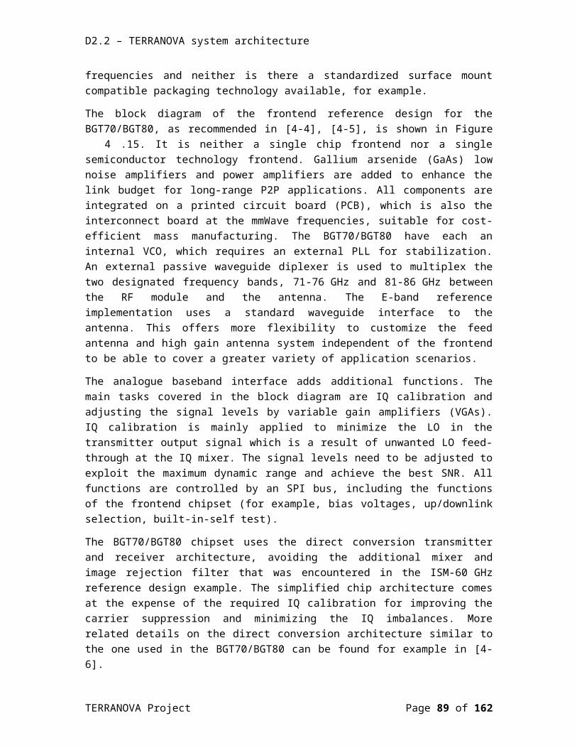
D2.2 – TERRANOVA system architecture
in the payload enables the station to associate to the PCP/AP in the association beamforming training (A-BFT) interval.
A-BFT is slotted and stations randomly choose one of the slots for transmitting sector sweep (SSW) or short SSW frames; consequently, collisions may occur when more than one STA chooses the same slot. Note that in order to accommodate a larger number of STAs attempting access during A-BFT, IEEE 802.11ay supports up to 40 A-BFT slots in each BI.
During an ATI, request and response frames are exchanged between the PCP/AP and any subset of STAs. The PCP/AP initiates all frame exchanges that occur during the ATI and schedules the transmissions to a non-PCP/non-AP STA. The non-PCP/non-AP STAs are not permitted to transmit, during the ATI except in response to a received individually addressed frame.
The BHI is followed by the DTI, which facilitates different types of medium access for data transmission and beamforming training. In the DTI, data frames can be exchanged either in contention-based access periods (CBAPs) or scheduled service periods (SPs) for contention-free communications.
In order to facilitate the coexistence of EDMG STAs with DMG STAs, the channel width of the primary channel is 2.16 GHz. When using channel aggregation, secondary channels might be adjacent or non-adjacent to the primary channel. EDMG STAs must be capable of performing physical and virtual carrier sensing (i.e., network allocation vector or NAV) in the primary channel and at least energy detection in the secondary channels. Physical carrier sensing is a measurement of the received signal strength of an incoming wireless fidelity (Wi-Fi) signal preamble, whereas energy detection determines if the medium is busy by measuring the total energy received at the station, regardless of whether it is a valid Wi-Fi preamble or not. Both methods compare the measurements with a pre-defined threshold. On the other hand, NAV maintains a prediction of future traffic on the medium based on duration information that is announced in RTS/CTS frames by non-DMG STAs and RTS/DMG CTS frames by DMG STAs prior to the actual exchange of data.
Moreover, in order to enable the coexistence of DMG and EDMG STAs, network announcement and management frames also need to be transmitted through the primary channel; hence, the BHI is present on the primary channel. IEEE 802.11ay supports the presence of A-BFT on secondary channels to provide more slots for contention-based transmission of SSW or short SSW frames in dense use cases. Transmissions within the DTI (CBAP or SP) can use more than one channel or be performed over a bonded channel. IEEE 802.11ay supports channel access over:
multiple channels through scheduling; and transmission opportunity (TXOP).
With multiple channels through scheduling, the AP/PCP specifies the channel width for the following DTI, whereas in TXOP, STAs expand their bandwidth opportunistically when secondary channels are idle. In more detail, in multiple channel access through scheduling, the AP/PCP is allowed to allocate aggregated and bonded channel(s) using the EDMG extended schedule element (ESE), which can be transmitted by the AP in the BTI. On the other hand, with TXOP, the
TERRANOVA Project Page 89 of 117
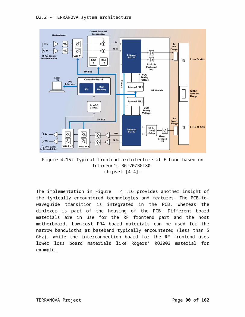
D2.2 – TERRANOVA system architecture
AP/PCP and STAs obtain a transmission opportunity (TXOP) either by winning an instance of EDCA contention or by receiving a Grant frame. When EDMG STAs and AP/PCP support multiple channel widths, an EDCA TXOP is obtained based solely on the activity of the primary channel, that is, if the primary channel is idle. However, the width of the transmission is determined by the occupancy status of the non-primary channels. Hence, the TXOP initiator monitors the status of its primary channel and possibly secondary channels during the point coordination function inter-frame space (PFIS) interval immediately preceding the expiration of the backoff counter (BOC) to determine the idle channels. Once the TXOP initiator finds the primary and secondary channels to be idle, it performs an RTS/DMG CTS exchange to inhibit collision on the secondary channel(s). The TXOP initiator sends RTS frames in the primary and secondary channels if they are determined to be idle to determine the available bandwidth at the responder. The TXOP responder then transmits a DMG CTS in the idle channels in order to help the TXOP initiator determine which channels are available for data transmission.
5.1.4 TAB-MACAssisted beamforming MAC protocol for THz communication networks (TAB-MAC) [5-13] exploits two different wireless technologies, namely, Wi-Fi at 2.4 GHz and THz-band communication, to drastically improve the throughput of wireless networks. The operation of the protocol is divided into two phases:
in Phase 1, nodes rely on the omnidirectional 2.4 GHz channel to exchange control information and coordinate their data transmissions; and
in Phase 2, nodes proceed with the actual data transfer at THz frequencies, after aligning their beams.
In more detail, during the phase 1, the transmitter sends one extended Request-To-Send (RTS) frame with Node Information, named as RTS-NI frame, which contains the information of node position. The receiver will reply an extended Clear-To-Send (CTS) frame with its Node Information, named as CTS-NI, when it is available. Once these two nodes obtained each other’s node positions, they can compute the LoS distance between them, and steer their beamforming antennas pointing to each other with a specific beamwidth. In order to be compatible with the existing MAC protocols, the frame header and footer are defined as in IEEE 802.11ac standard and the protocol specific information is transmitted as part of the Frame Body. The Frame Control field occupies 2 bytes. The type of frame is decided by the subfield type and subtype in Frame Control field as required. The Duration field with 2 bytes represents the life time of this frame. The size of the Address Information field depends on the frame type. For the RTS- NI and DATA frames, the Address Information field includes both the transmitter and receiver addresses, while it only contains the receiver address for the ACK and CTS-NI frames. Each address takes 6 bytes. The Sequence Control field is 2 bytes in length. The Frame Check Sequence (FCS) contains an IEEE 32-bit cyclic redundancy code (CRC).
After Phase 1, the beamforming antennas of the transmitter and receiver have been steered to point each other, i.e., the transmitter is ready to transmit data in the THz band. Firstly, in order to check the channel condition between the transmitter and the receiver, the transmitter will send one TTS frame to make sure that their directional antennas are pointing to each other and
TERRANOVA Project Page 90 of 117
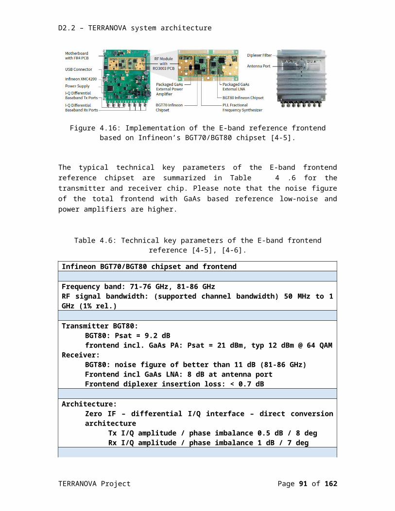
D2.2 – TERRANOVA system architecture
the LoS propagation between them is available. Once receiving the acknowledgement (ACK) from the receiver, the transmitter will begin the data transmission.
5.2 MAC protocolsThis section is focused on presenting the design principles and options of the TERRANOVA MAC. In more detail, in Section 5.2.1, we discuss the MAC protocol implementation options, whereas, in Section 5.2.2, we present the methods and tools that the Consortium will employ in order to evaluate their performance and quantify their effectiveness.
5.2.1 Implementation optionsAs we have seen in the discussion of reference methods in Section 5.1, different implementation options are available and have to be carefully balanced against each other in THz bands. For example, with pencil beamforming it is expected that contention-based schemes perform well since they naturally benefit from spatial multiplexing gain for concurrent transmissions. As shown in [5-1], even simple MAC methods such as slotted ALOHA may be very effective. Regarding, CSMA, a question has been raised as to how much the CA (collision avoidance) implementation option does really help. For TDMA-style options, if they do not take into account spatial multiplexing, they will lead to poor channel utilization. Polling is also an option. It must be ensured the mandatory silent periods in CSMA, such as DIFS/backoff etc., do not hinder transmission rate in the likely case of no interfering transmissions. These parameters could even be adaptive. However, there may be scenarios of very high deployment densities (such as in IoT) where we cannot ignore interference among simultaneous transmissions. It seems that MAC (and RRM) options for terahertz need to be able to deal with multiple different scenarios.
In the literature, received initiated MAC protocols have been presented as a way to guarantee alignment between the transmitter and receivers. This will be one implementation option for TERRANOVA, to be carefully evaluated. Based on the knowledge of location information (even possible indoors with the help of anchors), different MAC layers options become available. To support smooth operation and to reduce for example discovery times it is expected that out-of-band signalling in lower bands may be required, splitting parts of control and data planes into different frequencies. This has implications for MAC design.
Other implementation options to be considered include: ability to send within one packet to multiple directions either sequentially (by switching codebook) or by simultaneously (if hybrid or fully digital beamformers are used). These kinds of options will be very helpful for tracking the beam (once found). For example, within a packet using best-known current antenna pointing there could be small portion covering also adjacent antenna pointing in order to see if best parameters have changed.
5.2.1.1 Physical Control Channels implementation optionsBased on the trade-offs, provided in Section 2.3.2, as well as the communication modes, which will be used for the physical layer control channel realization, there are four possible realization options, namely:
TERRANOVA Project Page 91 of 117
D2.2 – TERRANOVA system architecture
Omni-directional-THz-control-channels-and-directional-data-channels: This option is useful for broadcasting/multicasting of control signals as well as for the utilization of random access inside small cells, since there is no need for spatial searching for UE detection and the deafness problem is eliminated. However, it is subject to the THz link instability and blockage. Additionally, this option leads to a mismatch between the transmission ranges of control and data (directional) channels, because of the much higher directivity gains of the latter.
Semi-directional-THz-control-channels-and-directional-data-channels: Again, this option is useful for multicasting of control signals inside small cells. Compared to the previous option, it extends the cell range and provides energy-efficiency transmission improvements, as well as efficient use of the spatial resources. However, this comes with an additional protocol complexity cost, due to the necessity of spatial search and the presence of the deafness and blockage problems. Finally, this option is subject to the THz link instability.
Fully-directional-THz-control-and-data-channels: This option demands a good BF alignment between the BS and UE, with a minimal use of the spatial resources. Compared to the second option, it further extends the cell range and improves the energy-efficiency and the efficiency in employing the spatial resources. On the other hand, this option requires the use of a spatial search mechanism for BS and UE discovery/tracking; hence, it comes with an additional complexity. Moreover, the complexity of the protocol is also increased, due to the deafness and blockage issues. Similarly, to the previous option, the fully-directional-THz-control-and-data-channels option is subject to the THz link instability.
Omni-directional-microwave-control-channel-and-directional-THz-data-channels: This option offers statistically larger range that is more stable in time than its THz counterparts. It was first introduced in the soft cell [5-2] and phantom cell [5-3] concepts, where the control plane is provided by a macrocell BS, whereas microcell BSs are responsible for providing only the data plane. Apart from being suboptimal in terms of energy efficiency, transmissions in a microwave band cannot provide accurate information for estimating the direction of arrival (DoA) in the THz band, due to different propagation characteristics. The main disadvantage of this option is its applicability for spatial synchronization and cell search procedures of THz networks.
Notice that in order to provide high-data rate communications in acceptable ranges, in all of the above realization options, we assumed that the data channels use the directional THz operation mode.
5.2.1.2 UE detection and trackingAn attractive solution for UE detection using analog beamforming, which has been suggested by several current standards, is a three-stage beam-searching technique to reduce alignment overhead. After a quasi-omnidirectional (low-resolution pattern) sweep, a coarse-grained sector-level sweep (second-level resolution pattern) is performed, followed by a beam-level refinement phase (the highest resolution pattern specified in the codebook). An exhaustive search over all possible transmission and reception directions is applied at each level through a sequence of pilot transmissions. The combination of vectors that maximizes the signal-to-noise
TERRANOVA Project Page 92 of 117
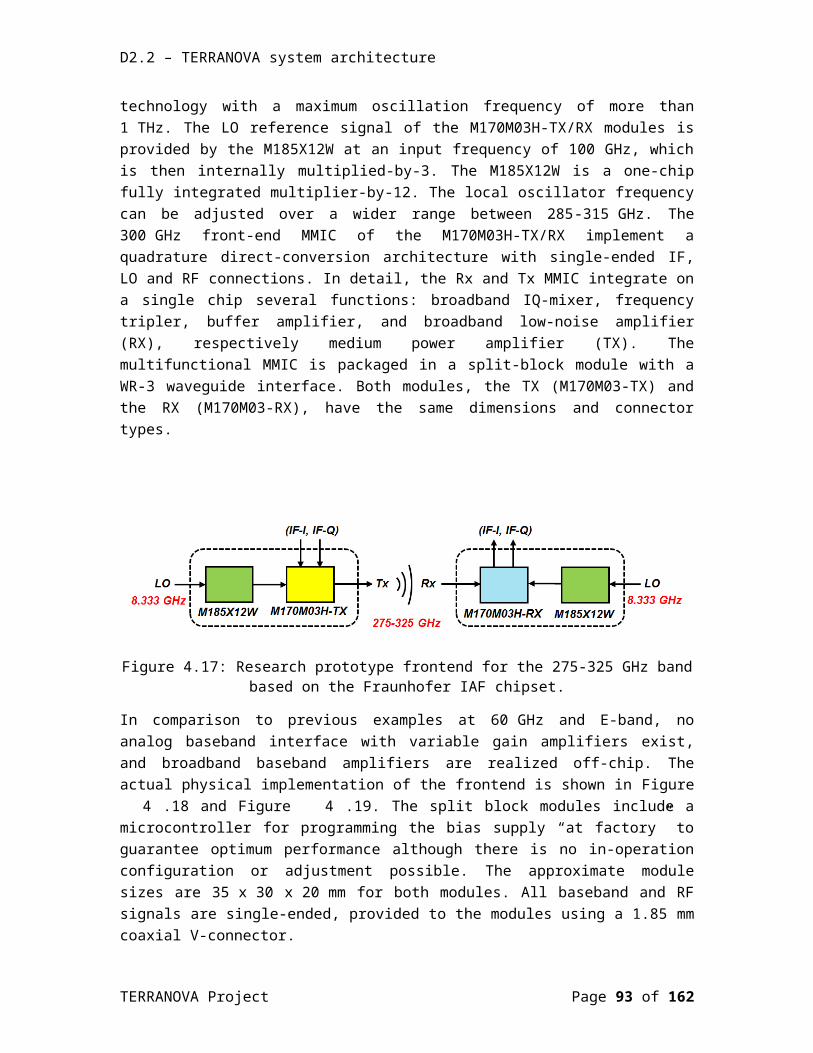
D2.2 – TERRANOVA system architecture
ratio (SNR) is then selected for the beamforming. For example, IEEE 802.11ad allows investigation of multiple beamforming vectors within a message, as opposed to sending separate training on each beamforming vector, which is the approach adopted in IEEE 802.15.3c. This modification makes it possible to explore multiple beam patterns with lower overall overhead in IEEE 802.11ad.
Moreover, in order to achieve the capacity-approaching performance, beamforming requires the BS to obtain the accurate information of the beamspace channel of large size. This is mainly caused by the fact that the user mobility usually leads to the fast variation of THz beamspace channels [5-14], [5-15], [5-16]. Conventional real-time channel estimation schemes require an unaffordable pilot overhead [5-17], [5-18]. As a consequence, more efficient (i.e. with lower pilot overhead tracking) schemes are employed in realistic applications. Existing beamspace channel tracking schemes can be classified into three categories. The first category is widely adopted at microwave frequencies, and its key idea is to model the time-varying channels in adjacent time slots by a one-order Markov process, and then the classical Kalman filter can be utilized to track the time-varying channels with low pilot overhead [5-19], [5-20]. However, the schemes, which belong in this category, require the modelling of the beamspace channels as one-order Markov process. On the other hand, the THz beamspace channels with special sparse structure cannot be modelled by the one-order Markov process. Therefore, this category of schemes cannot be directly extended to THz beamspace massive MIMO systems. The second category is usually applied at mmWave frequencies, which aims to search several candidate beam pairs for fast channel tracking by a beam training procedure between the BS and the UE [5-21], [5-22], [5-23], [5-24]. The con of the schemes in this category is that they are mainly designed for point-to-point scenarios, while for multiuser scenarios, the pilot overhead is still high [5-25]. Finally, the schemes in the third category, by considering practical user motion models, are able to excavate the temporal variation law of the physical direction between the BS and each mobile UE. After that, by combing the temporal variation law with the special sparse structure of the THz beamspace channels, they utilize the obtained beamspace channels in the previous time slots to predict the prior information of the beamspace channel in the following time slot without channel estimation. As a consequence, with the known supports, the time-varying beamspace channels can be tracked with low pilot overhead [5-26].
TERRANOVA Project Page 93 of 117

D2.2 – TERRANOVA system architecture
5.2.1.3 Initial access
Figure 5.33: Beamspace channel synchronization during initial access.
In this section, we consider the basic problem of initial access (IA), i.e., the procedure by which a UE discovers a potential THz BS and establishes a link-layer connection. IA is a basic prerequisite to any communication and is an essential component of all cellular systems. Although, it is relatively straightforward in 3GPP LTE, the IA procedure is complicated at THz frequencies, due to the highly-directional transmissions, which is needed in order to overcome the large free-space pathloss. In more detail, in LTE-A systems, acquiring time–frequency domain synchronization during cell search is facilitated by the so-called primary and secondary synchronization signals, transmitted omni-directionally in the downlink [5-27]. Each UE in the cell is aware a priori of when and where the synchronization control channel is, and thereby can extract synchronization signals along with cell identity. On the other hand, as illustrated in Figure 5.33, in addition to detecting the presence of the BS and access request from the UE, the THz IA procedure must provide a mechanism by which both the UE and BS can determine suitable BF directions, in which subsequent directional communication can be carried out. Note that due to the very high BF gains requirement, the angular search can cause a significant slowdown to the IA procedure, because of the potentially large beam search space. This potential increase in latency goes against one of the main objectives of the TERRANOVA system, which is to dramatically reduce latency. The added time for directional search in IA can slow what is known as control plane latency, which is the latency a UE experiences during the transition from idle mode to connected state.
TERRANOVA Project Page 94 of 117
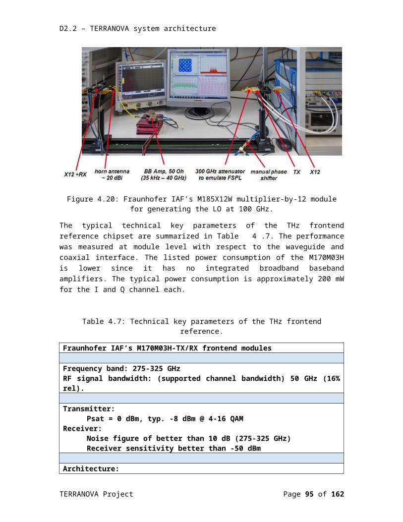
D2.2 – TERRANOVA system architecture
Figure 5.34: IA procedure.
In general, all the design options considered for IA follow the same basic steps shown in Figure5.34. The main steps of the IA procedure are identical to the ones used in the third generation partnership project (3GPP) LTE-A, which are described in [5-28]. However, the depicted procedure needs major modifications for THz to enable both the UE and the BS to determine the initial BF directions in addition to detecting the presence of the BS and the access request from the UE. In more detail, the IA steps are:
[S1] Synchronization and signal detection: During this step, each BS periodically transmits synchronization signals that the UE can scan to detect the presence of the base station and obtain the downlink frame timing. In LTE-A, the first synchronization signal to detect is the Primary Synchronization Signal (PSS). On the other hand, for THz systems, the synchronization signal will additionally be used to identify the UE’s BF direction, which (for analog BF) is related to the angles of arrival of the signal paths from the BS.
[S2] Random access (RA) preamble transmission: Motivated by the LTE-A uplink frame structure, we assume that the uplink contained dedicated slots exclusively for the purpose of RA messages. After [S1], the location of these slots is known to the UE. The UE transmits a RA preamble in one of the RA slots. Since the UE BF direction is known after step [S1], the RA preamble can be transmitted directionally. The BS scans for the presence of the RA preamble and learns the BF direction at the BS side.
[S3] RA response (RAR): After detecting a RA preamble, the BS transmits a RAR to the UE, which indicates the index of the detected response. At this point, both the BS and the UE know the
TERRANOVA Project Page 95 of 117

D2.2 – TERRANOVA system architecture
BF directions so all transmissions can obtain the full BF gain. The UE receiving the RAR knows its preamble was detected.
[S4] Connection request: After receiving RAR, the UE desiring initial access will send some sort of connection request message on the resources scheduled in the uplink grant in the RAR.
[S5] Scheduled communication: All subsequent communication can occur on scheduled channels with the full BF gain on both sides.
Note that this IA procedure was initially presented in [5-28].
5.2.1.4 Random accessAt the very beginning, a UE has no reserved channel to communicate with the BS(s) and can send a channel reservation request using contention-based or contention-free channel access. The contention-based requests, however, may collide due to simultaneous transmissions in the same cell, or not be received due to deafness. The comprehensive analysis of [5-4] shows that small to modest size mmWave networks operating with the slotted ALOHA protocol (a simple contention-based strategy) have a very small collision probability. In the contention-free scheme, the network defines and broadcasts multiple access signals that uniquely poll the individual UEs to avoid collisions. These signals should have spatial scheduling information to avoid deafness. Upon decoding a signal, each UE knows its uplink parameters: analog beam, random access preamble, and allocated resource for transmission of the preamble. Embedding all this information a priori is a challenging task especially due to the lack of spatial synchronization at the very beginning. As transmission and reception beamwidths become narrower, a reduced contention level makes contention-based procedures more justifiable than complex and wasteful contention-free ones [5-5].
5.2.1.5 Scheduled access Based on the directionality level, three scheduling scenarios are presented, namely:
Omni-directional communications; Semi-directional communications; and Fully-directional communications.
In omni-directional communications, the scheduling procedure is based on the orthogonal use of time-frequency resource blocks inside the cell.
In semi-directional communications, we assume that the BS can group UEs together based on the second order statistics of the channel and serves every UE group that have similar covariance matrix with one analog beamforming vector [5-29], [5-30]. In order to reuse time-frequency resource blocks for different groups, made by different analog beamformers, we need a time-frequency-space-dependent scheduling algorithm. As a result, the design of analog beamformers is a fundamental MAC layer problem, since analog beamforming vectors are spatial resources, which should be allocated to UEs together with time and frequency resources. Time-frequency scheduling should be recalculated after every channel coherence time and bandwidth, whereas spatial scheduling may be recalculated after a meaningful change in the covariance matrix of the channel, which is less frequent compared to the former. Moreover, in
TERRANOVA Project Page 96 of 117
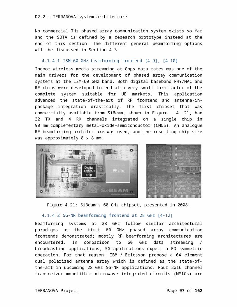
D2.2 – TERRANOVA system architecture
order to increase connection robustness to the blockages and provide smooth handover among groups, a UE can belong to several UE groups.
In fully-directional communications, the directionality of the communication links allows concurrent transmissions to take place at the same time without interfering with each other thus increasing the total throughput of the wireless system. To exploit this capability, the IEEE 802.11ad amendment defines a spatial sharing and interference mitigation mechanism to examine a set of established links for parallel communication. This mechanism relies on measuring the interference among communication links separated in time and space. A BS overlaps these links in time and assess the amount of interference introduced and its implication on the quality of the communication. If the BS foresees that the amount of interference induced to each link is negligible and does not affect the performance, then the BS schedule these links in the same time; thus, achieving spatial sharing and boosting system performance. As a result, the area spectral efficiency, measured in [bits/s/Hz/m2] is significantly increased.
5.2.1.6 Handover between multiple beamsIn order to avoid frequent handovers and reduce the overhead and the latency of re-association, the network should associate several BSs to each UE, by employing coordinate multi-point (CoMP) schemes. The cooperation among a UE, the associated BSs, and the macrocell BS can provide smooth seamless handover through efficient beam-tracking and finding alternative directed spatial channels in case of blockage. Here, two scenarios are foreseeable. A UE may receive data from several directions at the same time, but with a corresponding signal to noise ratio (SNR) loss for each beam, if we consider a fixed total power budget. Alternatively, a UE may be associated to several base (relay) stations, but only one of them is the serving BS whereas the others are used as backup.
This scenario demands joint scheduling. Moreover, backup connections enable switching without extra latency, if the alignment and association to backup BSs are done periodically. In the light of a user-centric design, the macro BS can record all connections of a UE, predict its mobility, give neighbouring BSs some side information indicating when the UE is about to make a handover, so they can better calibrate the directed channel and be ready for the handover. If the UE can be served from more than one BS, it will be connected to at least two of them in order to be able to conduct fast switch operation.
5.2.2 Evaluation methodology of functionality and complexityDifferent MAC protocols can be compared under the standard metrics such as throughput, latency, energy consumption, BER, support for various node densities and transmission ranges, etc. These values will be compared with the requirements of TERRANOVA use cases in order to confirm that the required QoS is reached. Other performance indicators, which will play significant roles in the case of IA and random access and are commonly used to evaluate the performance MAC protocols in systems that employ beamforming schemes, are the following:
False alarm probability (FAP); and Detection probability (DP) [5-31].
TERRANOVA Project Page 97 of 117
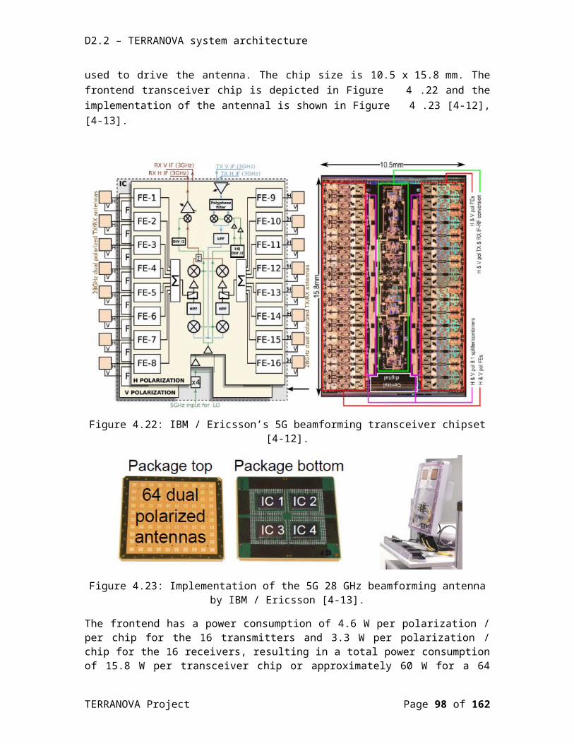
D2.2 – TERRANOVA system architecture
The FAP is the probability that a preamble sequence is detected when the preamble signatures are not transmitted from the BS or UE, during the corresponding random access frame. The miss DP is the probability that a preamble sequence is not detected when the preamble signature is transmitted in each random access slot in the corresponding random access frame.
Independently with the key performance indicator that will be evaluated, the comparisons will be carried out analytically and with simulation tools, such as in MATLAB and/or with specialized network simulation software such as ns-3.
5.3 RRM schemesRRM aims at utilizing the limited radio resources and radio network infrastructures as efficiently as possible in every communication system. In particular, RRM usually includes bandwidth management, transmission power management, antenna management and even access and data management. The ultimate goal of RRM is the optimization of overall system performance. Although, in the conventional wireless systems the RRM problems is becoming straightforward, the wireless communications in THz band have their unique characteristics inserting new challenges, requirements and even new fundamental performance limits. Specifically, the availability of high amounts of bandwidth, which is at the same time distance-dependent, the molecular absorption of the THz channel along with the pencil-beam antennas resulting in new channel and interference models with high propagation loss and consequently limited transmission range, lead the communication to take place in the extremely low SNR, but with an exceptionally large numbers of degrees of freedom. As a result, the conventional RRM approaches could not fit in the THz regime. Thus, new advanced RRM methods should be proposed taking into account the specific physical and medium access layers’ characteristics and fully addressing the emerged challenges. One of the major THz band peculiarities is the very strong relationship between the distance and the bandwidth requiring adaptation of the utilized bandwidth as a function of the distance. Moreover, the delay spread and the coherence bandwidth affect the physical parameters design in the communication scheme. Finally, the enormous usable bandwidth needs to be fully and efficiently exploited in multi-user/device networks, requiring a strategic spectrum utilization design, which simultaneously support multiple ultrahigh-speed links in the THz band.
Conventional RRM schemes do not take into consideration the particular characteristics of THz band channel and are designed mainly for omnidirectional antenna systems. As it is already mentioned, the super-wideband transmissions with pencil-beam antennas in THz systems and distance-dependent bandwidth, require new channel and interference models and as a result new information theoretic framework that will addressed by TERRANOVA. In such ultra-high data rates and ultra-low SNR regime, the trade-offs between the SNR, channel capacity, synchronization, transmission bandwidth and communication distance for the large amount of available transmission windows should be identified. Up to now, some studies have been presented for the RRM of 5G networks at mmWave frequencies [5-32], [5-33], while the literature for beyond 5G systems are extremely limited with [5-34] to discuss the modulation adaptation and the transmit power control problem in THz frequencies. Although taking into account the new proposed by TERRANOVA information theoretic framework, new RRM schemes will be presented. At first, since the antenna design is a major concept of the THz system
TERRANOVA Project Page 98 of 117
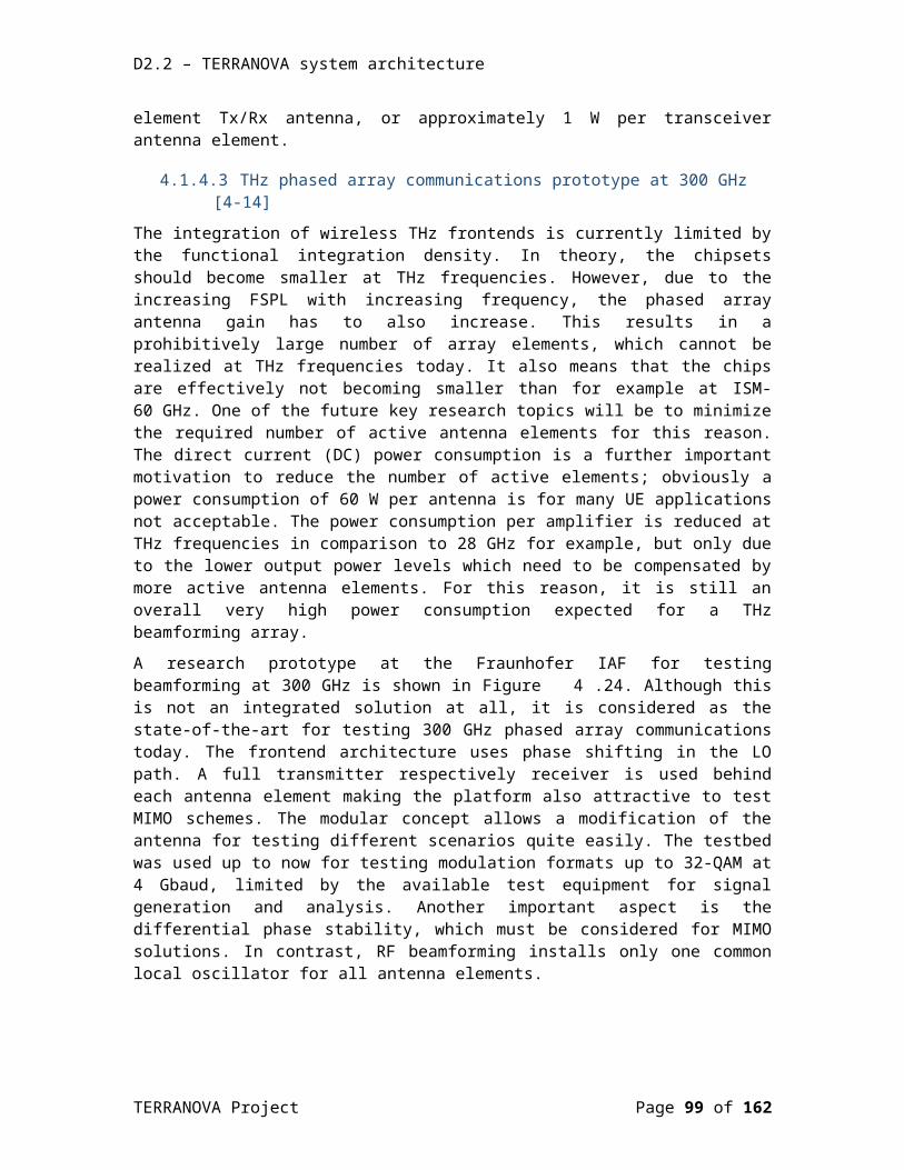
D2.2 – TERRANOVA system architecture
operation, TERRANOVA aims at an antenna management method for the effective operation of antennas adequate to the transformed THz channel and interference models. Cross-system hybrid beamforming methods and multi-spectrum approaches allowing for quick alignment based on lower frequency and refinements at higher frequency bands will be developed. Furthermore, new information encoding and modulation techniques as well as novel networking protocols more suited for THz devices will be proposed. Based on the aforementioned, i.e. the different nature of propagation and interference in terahertz networks and extreme directivity of THz links, a thorough rethinking of conventional multiplexing and network resources allocation approaches will be needed, examining how many ultrahigh-speed links can be simultaneously and efficiently supported in the THz band.
Having obtained the values of the fundamental, large-scale system parameters based on the analytical modelling studies, the next step towards an optimal resource allocation mechanism is the development of online algorithms for dynamically and efficiently allocating spectral and spatial resources to users/devices in various time-scales to guarantee differentiated QoS/QoE across multiple served users/devices (e.g., very fast for scheduling awaiting packets in the queues, modest for network reconfiguration due to the arrival of a new request). Each mechanism can be viewed as a solution to an optimization problem aiming at maximizing one or multiple key performance indicators (such as network and user throughput, energy efficiency, latency) without violating system operation assumptions. In particular, TERRANOVA will leverage latest developments in optimization theory and propose a highly adaptable framework for optimal RRM, combining various redesigned resource allocation techniques, in a distance-aware bandwidth-adaptive manner for multi-user/device highly densified THz band communication networks.
5.3.1 Implementation optionsIn this section, we present the implementation options for the RRM schemes. In more detail, in Section 5.3.1.1, we present the definition of the “Dynamic Cells”, which will be the building block of the BS-UE association scheme. Moreover, in the same section, we formulate the optimization problem, which will return the BS-UE association solution in a dense THz network.
5.3.1.1 Dynamic CellsAs mentioned above, due to the directionality of the THz link, the physical resource blocks should be defined not only in the time-frequency domain (as in LTE-A), but also in the space domain. This leads to a block in the time–frequency–space domain. Moreover, a group of UEs that are non-distinguishable in the transmitted beam should be grouped together.
Most of the current standards define a cell by the set of UEs that are associated using a minimum-distance rule, which leads to non-overlapping Voronoi tessellation of the serving area of every BS, exemplified by the well-known hexagonal cells [5-35], [5-36]. The minimum-distance rule leads to a simple association metric based on the reference signal received power (RSRP) and RSSI. However, the traditional RSRP/RSSI-based association may become significantly inefficient in the presence of non-uniform UE spatial distribution, and of heterogeneous BSs with a different number of antenna elements and different transmission powers [5-35], [5-37]. This association entails an unbalanced number of UEs per cell, which limits the available
TERRANOVA Project Page 99 of 117
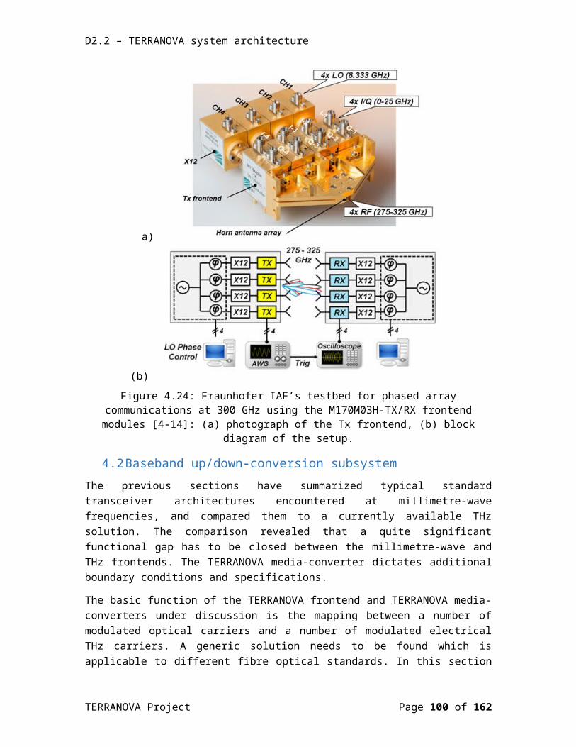
D2.2 – TERRANOVA system architecture
resources per UE in highly populated cells, irrespective of individual signal strengths, while wasting them in sparse ones. The main disadvantage of the current static definition of a cell, as a predetermined geographical area covered by a BS, is that the static cell formation is independent of the cell load as well as of the UE capabilities. Therefore, the parameters that should affect the cell formation are:
UE traffic demand; channel between UE and BSs; and BSs loads.
By taking into account, the massive number of degrees of freedom that fully-directional communication offers and possible MAC layer analog beamforming, we can define a dynamic cell as a set of not necessarily collocated UEs that are served by the same analog beamformer of the BS and dynamically selected to improve some objective function. Upon any significant fluctuations of the above three parameters, dynamic cell redefinition may be required. In this context, a full database in the macrocell BS is needed, which records the following attributes:
Dynamic cell formations; UE traffic demands; UE QoS levels; and UE connectivity to the neighboring BSs.
Depending on the UE demands, microcell BSs dynamically group UEs together and form new cells so that:
individual UE demands are met (QoS provisioning); the trade-off between macro-level fairness and spectral efficiency is improved - e.g.,
through proportional fair resource allocation (network utility maximization); and every UE is categorized in at least two groups, to guarantee robustness to blockage
(connection robustness).
TERRANOVA Project Page 100 of 117
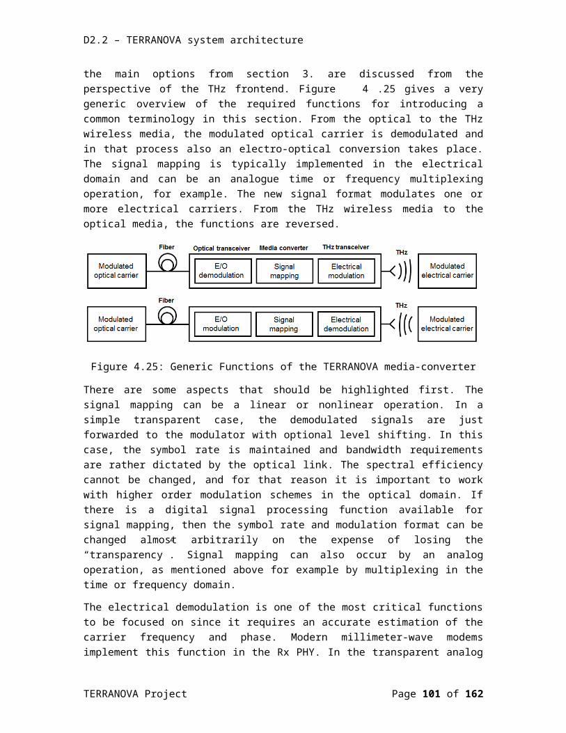
D2.2 – TERRANOVA system architecture
Figure 5.35: Dynamic cell network topology.
Based on the above criteria, we formulate the corresponding optimization problem for the BS-UE association, assuming a scenario, in which Nb BS can serve Nu UE (see Figure 5.35), in a full-directional mode. In this case the optimization problem can be formulated as follows:
TERRANOVA Project Page 101 of 117

D2.2 – TERRANOVA system architecture
where A is the set of UEs, B is the set of the BSs, θib and θ j
uare the operating beamwidths of the BS i and UE j, respectively, whereas, φ i
band φ ju the boresight angles of the BS and the UE.
Moreover, c ijdenotes the achievable rate of the link between the BS i and the UE j, while y ij represents the fraction of resources used by the BS i to serve the UE j. The association of the UE j with the BS i is represented by the binary variable x ij , which equals 1 if and only if the UE j is
associated to the BS i. The general utility function of r j=∑i∈Vy ij cijis represented as U j.
Additionally, θi , minb and θ j ,min
u are the minimum possible operating beamwidth of the BS i/UE j, whereas r j ,min is the minimum required bandwidth of the UE j. Finally, the matrices X and Y are formed by collecting all the control variables x ijand y ij ,respectively, whereas the vectors ϕb , ϕu ,θb ,θu are formed by the parameters ϕi
b , ϕ ju ,θ i
b ,θ ju , respectively.
Note that the solution of the above optimization problem provides a long-term association policy along with proper orientation and operating beamwidths. This solution ensures the optimal UE-BS association as long as the inputs of the optimization problem, namely network topology and UE demands, are unchanged. If a UE requires more resources or loses its connection, the optimization problem has to be re-executed.
5.3.2 Evaluation methodology of functionality and complexityThe functionality of all the proposed RRM schemes will be evaluated by respectful simulations, which will be carried out in MATLAB, or ns-3. Regarding on the type and the technical objective of the RRM scheme, it will be evaluated in terms of reliability, latency, and throughput. Moreover, in order to guarantee the feasibility and the practicality of the technique, the algorithm complexity will be derived.
TERRANOVA Project Page 102 of 117
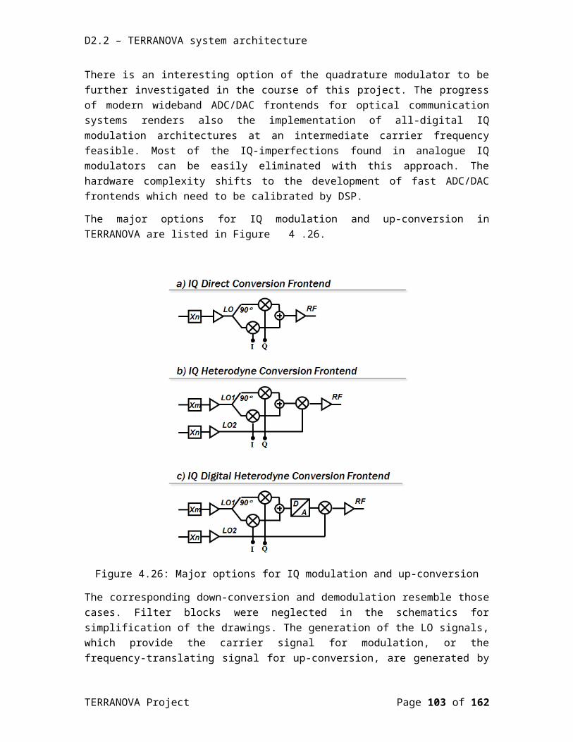
D2.2 – TERRANOVA system architecture
5.4 MetaMAC and caching schemesIn the P2MP scenario, the mobile user equipment (MUE) can be nomadic or mobile. In either case, the MUE can usually connect either simultaneously or sequentially to several access points (APs) using several Radio Access Technologies (RATs), such as THz, mmWave, microwave, etc. When the MUE initiates an application, this application may include several sessions, with different QoS requirements. As an example, a voice communication will require low latency and no disconnection, while video download will benefit from high capacity, with lower constraints on disconnection or latency. Therefore, it is particularly important to select the right RAT (or MAC domain) for each session, depending also on traffic load in each network.
Such coordination can be made usually by layer 4 protocols and above, with a central control. However, the case will often happen that local non-coordinated radio networks resources are also available. In that case network resources usage can be coordinated locally, taking into account layer 1 and 2 information from these different local RATs.
In such heterogeneous wireless network, the MetaMAC scheme is expected to contribute in selecting the suitable RATs, during session initiation and communication to respect the QoS requirement of a session [5-38]. Additionally, different caching schemes will mitigate the impact of specific channel impairments, such as disconnections or transmission capacity variations, and disconnection during handover. As described in 5.4.3, anticipating MUE handover by caching content in MUE, and prefetching content to the next cell will minimize disconnection effects. It is therefore important to ensure dynamic coordination between MetaMAC and caching schemes and strategy to optimize the MUE perceived QoS and to improve the bandwidth usage in the different RATs. The different mechanism and the principles of coordination between MetaMAC and caching are summarized below on a qualitative way.
The section details hereunder:
The MetaMAC or MAC coordination principles; The different caching schemes and coordination with MAC strategy.
TERRANOVA Project Page 103 of 117

D2.2 – TERRANOVA system architecture
5.4.1 System building blocks
Figure 5.36: System view of the different MetaMAC and caching building blocks.
Figure 5.36 describes the different building blocks including caching and (Meta) MAC:
The MAC Coordination Entity (MCE) communicates with the edge Signaling Entity and MAC controllers to select the appropriate network once a session is initiated by the MUE. Additionally, the MCE communicates with the Cache Controller to take into account caching strategies and decisions. An MCE controls a defined set of RAT. The number of RATs controlled by a unique MCE is just a question of implementation.
The Cache Controller controls the different cache nodes in the network, including definition of caching strategy, direct commands to cache content or transfer content from one cache to another caches. The Cache Controller has the knowledge of topology of cache nodes. The Cache Controller exchanges with the MAC Control Entity.
The MAC Controllers terminate and manage the MAC layer of each network connected to the MUE.
The Edge Signaling Entities are the edge terminating points for QoS signalling. They communicate with the MCE to transmit information of the QoS required by a session.
TERRANOVA Project Page 104 of 117
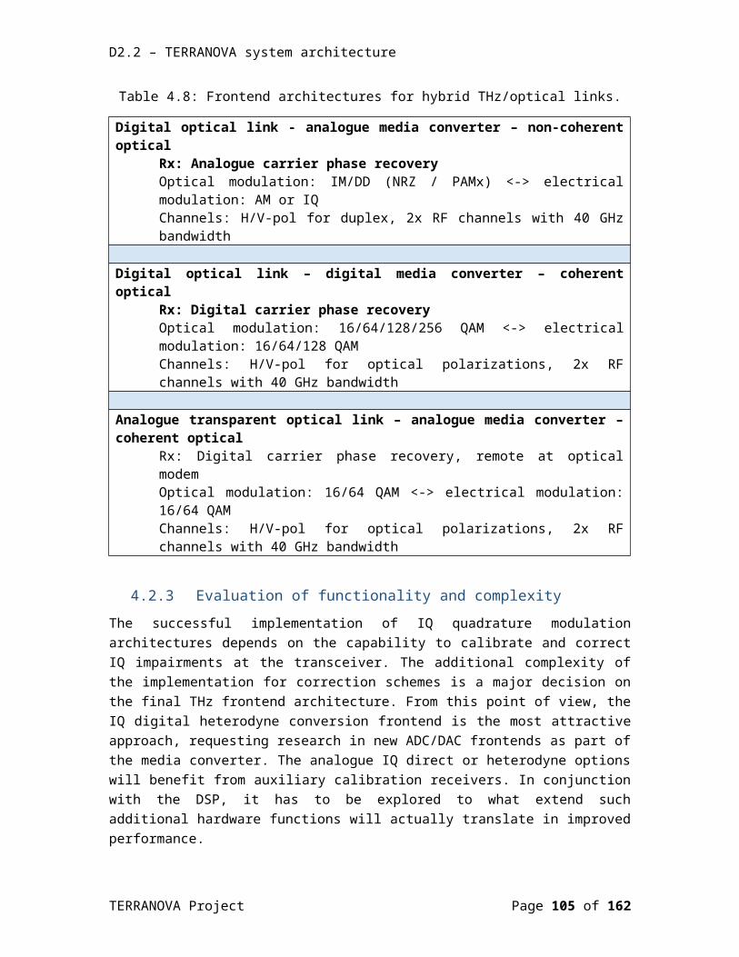
D2.2 – TERRANOVA system architecture
5.4.2 MetaMAC role and descriptionThe MetaMAC is performed by the MAC Coordination Entity. The authors, in [5-38], clarified that one option of MetaMAC is to coordinate several MAC domains (or RAT more precisely in our case) at the time slot level. This approach has several drawbacks, such as:
Requirement to have fine grain access to all MAC controllers; and Difficulty to consider a multi-operator case.
These drawbacks make this kind of implementation hardly applicable to current networks.
The preferred approach in the project is rather to define cross layer signaling between MAC controllers and MCE allowing to allocate and dynamically change sessions to different MAC domains. According to Figure 5.36, when a MUE opens a session:
The MUE can use an application layer protocol containing session requirements on QoS (in the form of a session description or QoS parameters); additionally, in the case the MAC layer is QoS aware, the user can send the same request at the MAC level.
The Edge entity then sends a cross-layer request to the MCE indicating the QoS requirement.
The MCE communicates with the different MAC controllers and takes the decision on the MAC layer to use. It sends back an acknowledgement to the Edge entity and the MAC controller
Once the MCE has selected the preferred MAC domains, it communicates with the Cache controller as some path could be preferred if content related to the session is already cached.
The same exchange can occur during the session if the MUE moves, or if changes occur in the network. Also note that the user could be connected to several MAC domain for the same session in the case the Layer 4 transport protocol allows it (MP-TCP, etc.)
5.4.3 In-network caching schemesThere are 2 mains caching schemes that are widely used:
PHY caching [5-39], which has an effect on the PHY layer performances; Caching unrelated to physical layer, taking into account content usage statistics, traffic
monitoring, and MUE handover [5-40].
The two caching schemes will work in coordination with the MAC layer selection; they are both controlled by the Cache Controller entity.
Only caching at the edge is addressed by the project. Referring to Figure 5.37, two main locations of cache node are:
CN cache (Central Node cache): at the MAC controller level; and Cache node at the cell location (PHY cache).
TERRANOVA Project Page 105 of 117

D2.2 – TERRANOVA system architecture
5.4.4 PHY caching
Figure 5.37: In-network caching schemes.
The PHY caching mechanism shown in Figure 5.37 will consist of downloading the same content chunks to several BSs, which are connected with the same MUE; by setting a virtual MIMO scheme. This is expected to improve the spectral efficiency of the PHY layer, at the expense of traffic in the fronthaul (and backhaul, if the content is not stored in the CN cache).
5.4.5 Caching related to upper layer informationCaching related to layer 2 and above will have 2 objectives:
Anticipate the handover of the MUE; this is particularly important in mmWave and THz cells, where the disconnection can be long during handover
Reduce traffic in the backhaul and/or fronthaul by caching individually content at the CN cache or PHY cache locations.
5.4.5.1 Caching related to handoverIn the case of a THz network, we can take the following assumptions:
The cell capacity is an order of magnitude higher than the session bit rate requirement, in order to allow fast content prefetching; and
The MUE can connect simultaneously to several cells (allowing mechanisms similar to CoMP).
The knowledge of both channel model and disconnection statistics due to handover will allow to determine the caching and prefetching strategies.
TERRANOVA Project Page 106 of 117
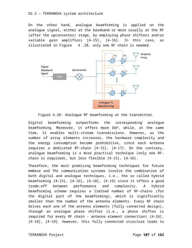
D2.2 – TERRANOVA system architecture
Under the assumptions above, caching can be made to improve the perceived QoS, even during disconnection (at the price of an additional latency). The caching strategy related to handover will also take into account MUE speed and direction, and will strongly interact with inter-cell coordination mechanisms and handover information. It will include content caching in the MUE and content prefetching in the next probable connected cells.
5.4.5.2 Caching related to network conditionUsually caching will be done in the CN cache to decrease the backhaul traffic, but it has also to take into account the usage statistics in each cell, and the storage capacity of each cache, requiring sharing the content between CN cache and PHY caches (hierarchical caching). These caching strategies will be under the control of the cache controller in coordination with the MCE.
5.5 References[5-1] H. Shokri-Ghadikolaei, C. Fischione, P. Popovski, and M. Zorzi, “Design aspects of short
range millimeter wave wireless networks: A MAC layer perspective,” IEEE Network, vol. 30, no. 3, pp. 88-96, May 2016.
[5-2] D. Astely, E. Dahlman, G. Fodor, S. Parkvall, and J. Sachs, “LTE release 12 and beyond,” IEEE Commun. Mag., vol. 51, no. 7, pp. 154–160, Jul. 2013.
[5-3] H. Ishii, Y. Kishiyama, and H. Takahashi, “A novel architecture for LTE-B: C-plane/U-plane split and phantom cell concept,” in Proc. IEEE GLOBECOM Workshops, 2012, pp. 624–630.
[5-4] H. Shokri-Ghadikolaei and C. Fischione, “The transitional behavior of millimeter wave networks,” KTH, Tech. Rep., May 2015.
[5-5] C. Jeong, J. Park, and H. Yu, “Random access in millimeter-wave beamforming cellular networks: Issues and approaches,” IEEE Commun. Mag., vol. 53, no. 1, pp. 180–185, Jan. 2015.
[5-6] N. Golrezaei, A. G. Dimakis, and A. F. Molisch, “Scaling behavior for device-to-device communications with distributed caching,” IEEE Trans. Inf. Theory, vol. 60, no. 7, pp. 4286–4298, Jul. 2014.
[5-7] L. Bao, J. Garcia-Luna-Aceves, “Transmission scheduling in ad hoc networks with directional antennas”, in Proc. 8th Annual International Conference on Mobile Computing and Networking, ACM, 2002, pp. 48–58.
[5-8] R.R. Choudhury, X. Yang, R. Ramanathan, N.H. Vaidya, “Using directional antennas for medium access control in ad hoc networks”, in Proc. 8th Annual International Conference on Mobile Computing and Networking, ACM, 2002, pp. 59–70.
[5-9] R. Ramanathan, J. Redi, C. Santivanez, D. Wiggins, S. Polit, “Ad hoc networking with directional antennas: a complete system solution”, IEEE J. Sel. Areas Commun., March 2005, pp. 496–506.
[5-10] T. S. Rappaport et al., “Millimeter Wave Wireless Communications”, Pearson Education, 2014.
[5-11] M. Ji, G. Caire, and A. F. Molisch, “The throughput-outage tradeoff of wireless one-hop caching networks,” IEEE Trans. Inf. Theory, vol. 61, no. 12, pp. 6833–6859, Dec. 2015.
TERRANOVA Project Page 107 of 117
D2.2 – TERRANOVA system architecture
[5-12] T. Nitsche et al., “IEEE 802.11ad: Directional 60 GHz Communication for Multi-Gigabit-per-Second Wi-Fi,” IEEE Commun. Mag., vol. 52, no. 12, Dec. 2014, pp. 132–41.
[5-13] X.-W. Yao and J.-M. Jornet, “TAB-MAC: Assisted beamforming MAC protocol for Terahertz communication networks,” Nano Communication Networks, vol. 9, Sep. 2016, pp. 36-42.
[5-14] S. Mumtaz et al., “Cognitive vehicular communication for 5G,” IEEE Commun. Mag., vol. 53, no. 7, pp. 109–117, Jul. 2015.
[5-15] S. Mumtaz, S. Huq, K. Mohammed, and J. Rodriguez, “Direct mobile-to-mobile communication: Paradigm for 5G,” IEEE Wireless Commun., vol. 21, no. 5, pp. 14–23, Oct. 2014.
[5-16] L. Dai, Z. Wang, and Z. Yang, “Spectrally efficient time-frequency training OFDM for mobile large-scale MIMO systems,” IEEE J. Sel. Areas Commun., vol. 31, no. 2, pp. 251–263, Feb. 2013.
[5-17] Z. Gao, L. Dai, Z. Wang, and S. Chen, “Spatially common sparsity based adaptive channel estimation and feedback for FDD massive MIMO,” IEEE Trans. Signal Process., vol. 63, no. 23, pp. 6169–6183, Dec. 2015.
[5-18] L. Dai, J. Wang, Z. Wang, P. Tsiaflakis, and M. Moonen, “Time domain synchronous OFDM based on simultaneous multi-channel reconstruction,” in Proc. IEEE Int. Conf. Commun., Jun. 2013, pp. 2984–2989.
[5-19] O. Mehannaand N. Sidiropoulos, “Channel tracking and transmit beamforming with frugal feedback,” IEEE Trans. Signal Process., vol. 62, no. 24, pp. 6402–6413, Dec. 2014.
[5-20] N. Kabaoglu, “Target tracking using particle filters with support vector regression,” IEEE Trans. Veh. Technol., vol. 58, no. 5, pp. 2569–2573, Jun. 2009.
[5-21] S. Hur, T. Kim, D. Love, J. Krogmeier, T. Thomas, and A. Ghosh, “Millimeter wave beamforming for wireless backhaul and access in small cell networks,” IEEE Trans. Commun., vol. 61, no. 10, pp. 4391–4403, Oct. 2013.
[5-22] J. Wang et al., “Beam codebook based beamforming protocol for multi-Gbps millimeter-wave WPAN systems,” IEEE J. Sel. Areas Commun., vol. 27, no. 8, pp. 1390–1399, Oct. 2009.
[5-23] M. Cudak, T. Kovarik, T. A. Thomas, A. Ghosh, Y. Kishiyama, and T. Nakamura, “Experimental mmWave 5G cellular system,” in Proc. IEEE Globecom Workshops, Dec. 2014, pp. 377–381.
[5-24] Z. Xiao, T. He, P. Xia, and X.-G. Xia, “Hierarchical codebook design for beamforming training in millimeter-wave communication,” IEEE Trans. Wireless Commun., vol. 15, no. 5, pp. 3380–3392, May 2016.
[5-25] R. Mendez-Rial, C. Rusu, A. Alkhateeb, N. Gonzalez-Prelcic, and R. W. Heath, “Channel estimation and hybrid combining for mmWave: Phase shifters or switches?” in Proc. Inf. Theory Appl. Workshops, Feb. 2015, pp. 90–97.
[5-26] X. Gao, L. Dai, Y. Zhang, T. Xie, X. Dai and Z. Wang, "Fast Channel Tracking for Terahertz Beamspace Massive MIMO Systems," in IEEE Trans. Vehicular Technology, vol. 66, no. 7, pp. 5689-5696, Jul. 2017.
[5-27] S. Sesia, I. Toufik, and M. Baker, LTE: The UMTS Long Term Evolution. New York, NY, USA: Wiley Online Library, 2009.
TERRANOVA Project Page 108 of 117
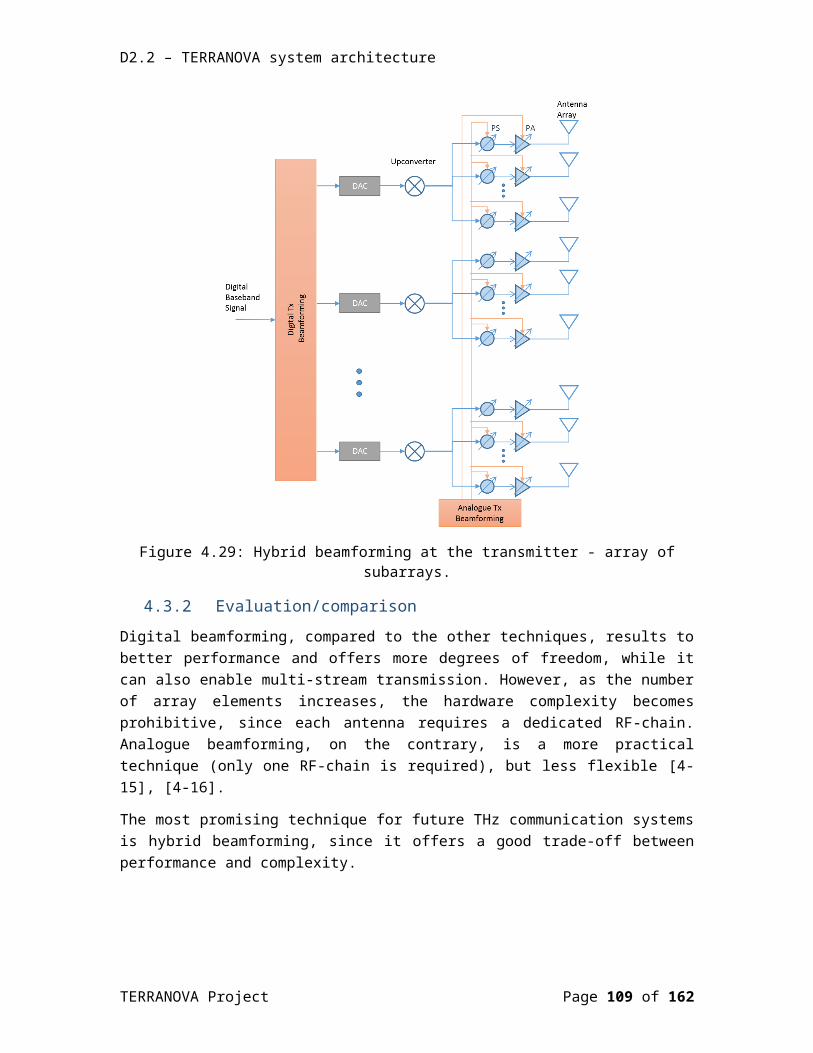
D2.2 – TERRANOVA system architecture
[5-28] C. N. Barati et al., "Initial Access in Millimeter Wave Cellular Systems," in IEEE Trans. on Wireless Communications, vol. 15, no. 12, pp. 7926-7940, Dec. 2016.
[5-29] A. Adhikary, J. Nam, J. Ahn, and G. Caire, “Joint spatial division and multiplexing-the large-scale array regime,” IEEE Trans. Inf. Theory, vol. 59, no. 10, pp. 6441–6463, Oct. 2013.
[5-30] R. Taori and A. Sridharan, “Point-to-multipoint in-band mmWave back- haul for 5G networks,” IEEE Commun. Mag., vol. 53, no. 1, pp. 195–201, Jan. 2015.
[5-31] C. Jeong, J. Park and H. Yu, "Random access in millimeter-wave beamforming cellular networks: issues and approaches," in IEEE Commun. Mag., vol. 53, no. 1, pp. 180-185, Jan. 2015.
[5-32] S.T. Shah, J.S. Kim, E.S Bae, J. Bae, M.Y. Chung, “Radio resource management for 5G mobile communication systems with massive antenna structure,” Trans. on Emerging Telecommunications Technologies, Volume 27, Issue 4, 2016.
[5-33] J. Park, S. L. Kim and J. Zander, "Tractable Resource Management With Uplink Decoupled Millimeter-Wave Overlay in Ultra-Dense Cellular Networks," in IEEE Trans. Wireless Commun., vol. 15, no. 6, pp. 4362-4379, June 2016.
[5-34] C. Han and I. F. Akyildiz, "Distance-Aware Bandwidth-Adaptive Resource Allocation for Wireless Systems in the Terahertz Band," in IEEE Trans. Terahertz Science and Technology, vol. 6, no. 4, pp. 541-553, July 2016.
[5-35] J. G. Andrews,S. Singh,Q. Ye,X. Lin,and H .S. Dhillon,“An overview of load balancing in HetNets: Old myths and open problems,” IEEE Wireless Commun., vol. 21, no. 2, pp. 18–25, Apr. 2014.
[5-36] H.-S. Jo, Y. J. Sang, P. Xia, and J. G. Andrews, “Heterogeneous cellular networks with flexible cell association: A comprehensive downlink SINR analysis,” IEEE Trans. Wireless Commun., vol. 11, no. 10, pp. 3484–3495, Oct. 2012.
[5-37] G. Athanasiou, C. Weeraddana, C. Fischione, and L. Tassiulas, “Optimizing client association in 60 GHz wireless access networks,” IEEE Trans. Netw., vol. 23, no. 3, pp. 836–850, Jun. 2015.
[5-38] András Faragó, Andrew D. Myers, Violet R. Syrotiuk, and Gergely V. Záruba, “Meta-MAC Protocols: Automatic Combination of MAC Protocols to Optimize Performance for Unknown Conditions,” IEEE J. Sel. Areas Commun., vol. 18, no. 9, Sep. 2000, pp. 1670 – 1681.
[5-39] Wei Han, An Liu, and Vincent K. N. Lau, “PHY caching in wireless networks: Design and Analysis,” IEEE Comm. Mag., Aug. 2016, pp. 30-36.
[5-40] Omid Semiari, Walid Saad, Mehdi Bennis, and Behrouz Maham, “Caching Meets Millimeter Wave Communications for Enhanced Mobility Management in 5G Networks“, IEEE Trans. Wireless Commun., Nov. 2017, pp. 779-793.
TERRANOVA Project Page 109 of 117

D2.2 – TERRANOVA system architecture
6.TERRANOVA CANDIDATE ARCHITECTURESIn the following, we will summarize the ideas from the previous chapters and present candidate architectures for implementation for each of the relevant TERRANOVA scenarios as defined in D2.1 [6-1] and recapitulated in Section 2.1.
6.1 Scenario 1: Point-to-point Figure 6.38 shows two candidate architectures for the implementation of the point-to-point link of scenario 1 while the specifications are listed in Table 6.9. The main research aspect of these architectures is the realization of a combined optical/THz link providing transparency for the signals on the physical layer without digital signal processing at optical/THz interface. For both architectures, a full-duplex symmetric link type is assumed, as well as the use of a single frequency window from 220 GHz – 300 GHz. Candidate (a) follows the transparent optical link architecture described in Section 3.2.2, while candidate (b) follows the digital optical link architecture with analogue media converter described in Section 3.2.1.
L2 switch L2 switch
CFP2ACO
CFP2 ACO
L2 switch L2 switch
N ×XFP
MUXDEMUX
DSP DAC
ADCADCDAC DS
PCFP2 ACO
CFP2 ACO
MUXDEMUX
THz frontend THz frontend
THz frontend THz frontend
N ×XFP
N ×XFP
N ×XFP
(a)
(b)
Figure 6.38: Candidate architectures for the implementation of scenario 1 (point-to-point).
Table 6.9: Specifications of candidate architectures for the implementation of scenario 1 (point-to-point).
Candidate architecture (a) Candidate architecture (b)Link type LOS, FD, symmetric LOS, FD, symmetricDuplex implementation Frequency Polarization or frequencyExpected throughput Up to 1 Tb/s full duplex Up to 200 Gb/s full duplex Used frequency window 220 GHz – 300 GHz 220 GHz – 300 GHz
Optical channel SSMF SSMFOptical transceiver CFP2-ACO XFP
TERRANOVA Project Page 110 of 117

D2.2 – TERRANOVA system architecture
Optical modulation Single-carrier PDM-QAM N x NRZTHz modulation Single-carrier PDM-QAM and
multi-carrier schemes (OFDM)
PAM4
Media converter typeNot required
Analog MUX:1:N/2 TDM rate conversionNRZ-to-PAM4 conversion
THz frontend type Double I/Q DSB AM + Envelope detectionTHz frontend bandwidth (RF)
40 GHz 80 GHz
THz antenna 2 polarizations (for polarization multiplexing)
2 polarization in case of polarization duplexing;1 polarization in case of frequency duplexing
Beam forming type High gain High gain
Dynamic beam steeringSmall angle Small angleDue to the fixed position, there is low beam steering requirements.
Dynamic UE detection Not requiredSpatial synchronization Required
Network Caching Required to reduce latencyPHY Caching Not required
CoMP Not required
6.2 Scenario 2: Point-to-multipointThe candidate architectures for scenario 2 (point-to-multipoint) are shown in Figure 6.39 and Figure 6.40, with the specifications listed in Table 6.10 and Table 6.11. Here, the main research aspect is the implementation of P2MP architectures that provide functionality beyond traditional broadcasting, thereby leveraging on THz pencil beamforming. Both architectures follow the “digital optical link and digital media converter” architecture described in Section 3.2.3. In candidate architecture (a), the link between the single (macro) site to multiple (micro) sites is realized by space- and –time-division multiplexing (downlink) and multiple access (uplink), as the macro site beam is steering sequentially to each of the micro sites. Therefore, the macro site beam must be steered over large angles, while micro site beam does not require this.
TERRANOVA Project Page 111 of 117
D2.2 – TERRANOVA system architecture
L2 switch
L2 switch
L2 switch
L2 switch
DSP DAC
ADC
THz frontend
THz frontend
THz frontend
THz frontend
ADCDAC DS
P
ADCDAC DS
P
ADCDAC DS
P
N ×XFP
N ×XFP
Figure 6.39: Candidate architecture (a) for the implementation of scenario 2 (point-to-multi-point).
Table 6.10: Specifications of candidate architecture (a) for the implementation of scenario 2 (point-to-multi-point).
Candidate architecture (a)Link type LOS, symmetric FD (per time slot)Duplex implementation Frequency Used frequency window 220 GHz – 300 GHzMulti-user access Space and time-division multiple access
Optical channel SSMFOptical transceiver XFPOptical modulation N x NRZMedia converter type Digital (DSP + DAC/ADC)
Downlink UplinkExpected throughput Up to 500 Gb/s
(e.g. 38-GBd PDM-256-QAM single carrier)
Up to 500 Gb/s shared by N users(e.g. 38-GBd PDM-256-QAM single carrier)
THz frontend type Double I/Q Double I/QTHz frontend bandwidth 40 GHz 40 GHzTHz antenna 2 Polarizations (for
polarization multiplexing)2 Polarizations (for polarization multiplexing)
Beam forming type High gain, space-division multiple access
High gain, space-division multiple access
Dynamic beam steering Large angle Small angle
Dynamic UE discovery Fast and accurate with low discovery overhead. -
Spatial synchronization Required
TERRANOVA Project Page 112 of 117
D2.2 – TERRANOVA system architecture
Network Caching Required to reduce latency
PHY Caching Required to manage mobility and handoversCoMP Required to manage mobility and handovers
Alternatively, the downlink can be realized by using spatial multiplexing only (candidate architecture b). That is, multiple fixed beams are employed to simultaneously transmit traffic to every micro site (Figure 6.40, Table 6.11). This option increases significantly the throughput per link (per user), but it also increases the hardware complexity (antennas, RF chains, etc.), in order to support multiple beams that are associated to multiple data streams.
L2 switch
L2 switch
L2 switch
L2 switch
DSP DAC
ADC
THz frontend
THz frontend
THz frontend
THz frontend
ADCDAC DS
P
ADCDAC DS
P
ADCDAC DS
P
N ×XFP
N ×XFP
Figure 6.40: Candidate architecture (b) for the implementation of scenario 2 (point-to-multi-point).
Table 6.11: Specifications of candidate architecture (b) for the implementation of scenario 2 (point-to-multi-point).
Candidate architecture (b)Link type LOS, symmetric (in terms of throughput per link)Duplex implementation FrequencyUsed frequency window 220 GHz – 300 GHzMulti-user access STMA
Optical channel SSMFOptical transceiver XFPOptical modulation N x NRZMedia converter type Digital (DSP + DAC/ADC)
Downlink UplinkExpected throughput Up to 500 Gb/s per link Up to 500 Gb/s per link
TERRANOVA Project Page 113 of 117

D2.2 – TERRANOVA system architecture
(e.g. 38-GBd PDM-256-QAM single carrier)
(e.g. 38-GBd PDM-256-QAM single carrier)
THz frontend type Double I/Q Double I/QTHz frontend bandwidth (RF)
40 GHz 40 GHz
THz antenna 2 Polarizations (for polarization multiplex)
2 Polarizations (for polarization multiplex)
Beam forming type High gain, SDMA High gain, SDMADynamic beam steering Large angle Small angle
Dynamic UE discovery Fast and accurate with low discovery overhead. -
Spatial synchronization RequiredNetwork Caching Required to reduce latencyPHY Caching Required to manage mobility and handoversDynamic UE discovery Fast and accurate with low discovery overhead.Spatial synchronization RequiredNetwork Caching Required to reduce
latencyPHY Caching Required to manage mobility and handoversCoMP Required to manage mobility and handovers
6.3 Scenario 3: Indoor quasi-omnidirectionalThe candidate architecture for scenario 3 (indoor quasi-omnidirectional) is shown in Figure 6.41, with the specifications listed in Table 6.12. Here, the main research aspect is the implementation of a THz system that can provide a high spatial and angular coverage for nomadic and mobile applications. The architecture follows the “digital optical link and digital media converter” architecture described in Section 3.2.3. It is assumed that only the downlink to multiple UEs is using THz while the uplink might be realized with other technologies. The downlink uses M beams which broadcast the same data to different parts of the room. The indoor scenario as well as the presence of multiple beams requires to consider the downlink as NLoS link with multipath fading.
L2 switch
DSP DAC
ADC
THz frontend
N ×XFP
N ×XFP
UE
UE
UE
Figure 6.41: Candidate architecture for the implementation of scenario 3 (indoor quasi-omnidirectional).
TERRANOVA Project Page 114 of 117
D2.2 – TERRANOVA system architecture
Table 6.12: Specifications of the candidate architecture for the implementation of scenario 3 (indoor quasi-omnidirectional).
Candidate architectureLink type NLOS, half duplexDuplex implementation THz downlink (uplink with other technologies)Used frequency window 220 GHz – 300 GHzMulti-user access TDMA
Optical channel SSMFOptical transceiver XFPOptical modulation N x NRZMedia converter type Digital (DSP + DAC/ADC)
DownlinkExpected throughput Up to 400 Gb/s shared by multiple users
(e.g. 64-GBd 256QAM single carrier)THz frontend type I/Q THz frontend bandwidth (RF)
80 GHz
THz antenna M antennas for multiple indoor beamsBeam forming type High opening angle for high coverageDynamic beam steering Not requiredNetwork Caching Required to reduce latencyPHY Caching Required to manage mobility and handoversDynamic UE discovery Fast and accurate with low discovery overhead.Spatial synchronization Not requiredCoMP Required to ensure coverage
6.4 References[6-1] EU Project TERRANOVA (grant agreement 761794), D2.1: TERRANOVA System
Requirements, public deliverable, v1.0, December 2017, ict-terranova.eu
TERRANOVA Project Page 115 of 117

D2.2 – TERRANOVA system architecture
7.CONCLUSIONS This deliverable presented the reference scenarios and implementation options for the TERRANOVA system architectures. Although the development of the THz wireless system and baseband interface is in its early stage and hence, it is difficult to state precisely what the final system will be, it is already possible to identify the critical technology gaps, the appropriate enablers, which will boost the system utilization and efficiency, and provide research directions.
In this deliverable, these aspects were discussed in detail with regards to the overall hybrid optical/THz system co-design, the broadband THz frontend as well as the PHY and the MAC/RRM protocols. In particular, reference (SOTA) architectures were presented for each of the main constituents of the TERRANOVA system, which provide important base lines for the development of new functionalities, which are required in order to cope with the particularities of each identified application scenario and achieve the targeted KPIs.
From the physical layer perspective, fundamental inherent characteristic of transmission in the THz regime were discussed, namely the extreme bandwidth, the extremely small wavelength and the associated high attenuation as well as the material absorption, molecular absorption and the resulting frequency and distance dependent pathloss. It was hence recognised that the employment of pencil beamforming techniques is required in order to cope with distance-dependent performance (w.r.t. SNR, available bandwidth, spectral efficiency, etc) along with adaptive modulation and coding techniques and transmission through multiple frequency windows and multiple spatial modes.
The directional, ‘beamspace’, channel system model, resulting from the employment of pencil beamforming, calls for a suitable (‘directional’) MAC and RRM design, capable to address the challenges blockage, deafness, spectrum heterogeneity, detection and tracking agility and interference management. Both random and scheduled access need to be considered in order to strike the right balance between complexity and adaptability and at the same time support the directional (‘beamspace’) and multi-user (point to multi-point) scenarios.
With respect to the hybrid optical/THz system co-design, a brief review of wireless transmission reference systems and relevant standards was first presented (associated with the identified three basic topological application scenarios) and then optical transmission reference systems and relevant standards were discussed. Three interface implementation options were then described for the realization of the hybrid optical/ THz. A comparative analysis of the three presented architectures for the hybrid optical/THz link was performed, where it became apparent that the final selection among them is to a large extent application-dependent.
With regards to THz frontend, reference components and technologies were analysed, namely ISM-60 GHz, E-band and first generation THz frontend research prototypes (non-commercially available) as well as beamforming frontends for 5G, 60 GHz WiGig and 300 GHz THz links. The analysis of typical standard transceiver architectures employed in millimetre-wave frequencies and comparison to the currently available THz solutions revealed that a quite significant functional gap has to be closed between the millimetre-wave and THz frontends. In that respect,
TERRANOVA Project Page 116 of 117
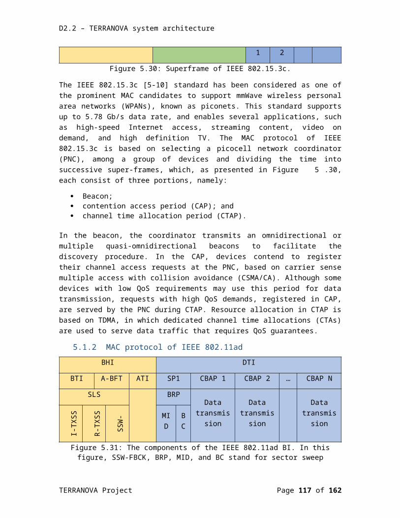
D2.2 – TERRANOVA system architecture
the TERRANOVA media-converter imposes additional boundary conditions and specifications. The basic function of the TERRANOVA frontend and TERRANOVA media-converters is the mapping between a number of modulated optical carriers and a number of modulated electrical THz carriers. A generic solution needs to be devised, which is applicable to different fibre optical standards and compatible with the selected options for the architectures of the hybrid optical/THz link.
With regards to the beamforming subsystem, a classification of different beamforming options was presented (relevant to the TERRANOVA system concept and application scenarios) and appropriate THz antenna options were discussed.
From MAC/RRM protocol perspective, relevant reference MAC protocols were analysed, namely the IEEE 802.15.3c, IEEE 802.11ad, and IEEE 802.11ay MAC protocols along with the assisted beamforming MAC protocol for THz communication networks (TAB-MAC). The most critical functionalities and their respective implementations options were then discussed, i.e. physical control channel implementation, UE detection and tracking, random access, scheduled access and handover between beams.
In terms of RRM, the importance of dynamic cell formation and UE-BS association was emphasized and the corresponding optimization problem formulation was briefly discussed. Moreover, the benefits of device caching in terms of offloading and throughput performance need also to be considered in the overall system architecture.
Finally, specific candidate system architectures were presented for the three main technical scenarios in TERRANOVA, namely outdoor fixed P2P, outdoor/indoor individual P2MP, and outdoor/indoor “quasi”-omnidirectional links. From today’s perspective, these candidate architectures are designed in order to provide full support for the previously identified target KPIs in each scenario. However, there are still several aspects and issues that need careful theoretical analysis, algorithm and protocol design, practical implementation and experimental validation to confirm their suitability to meet the KPIs. The required actions will be taken in the course of the TERRANOVA project within the framework of the corresponding tasks and workpackages.
TERRANOVA Project Page 117 of 117