icp ext-04-00659 · icp/ext-04-00659 project no. 22901 esp ... aa alternate action ... the project...
TRANSCRIPT
ICP/EXT-04-00659Project No. 22901
ESP-122-04
Field Sampling Plan for TSF-09/18 V-Tanks Phase I Treatment
January 2005
Idaho Completion Project Idaho Falls, Idaho 83415
Prepared for the U.S. Department of Energy
Assistant Secretary for Environmental Management Under DOE Idaho Operations Office
Contract DE-AC07-99ID13727
iii
ABSTRACT
This Field Sampling Plan establishes the procedures and requirements for
conducting sampling of treated V-tank contents waste after Phase 1 treatment (air-sparging) to confirm the non-characteristic nature of the waste, determine if
the treated waste meets the land disposal restrictions treatment standards for
organic constituents, and to determine the extent of additional treatment during
Phase 2, if necessary. This sampling and analysis activity supports the TSF-09/18 V-tanks remediation for Operable Unit 1-10 at Test Area North.

iv

v
CONTENTS
ABSTRACT .......................................................................................................................................... iii
ACRONYMS......................................................................................................................................... ix
1. INTRODUCTION...................................................................................................................... 1-1
1.1 Project Objectives.......................................................................................................... 1-2
1.2 Site and Waste Description ............................................................................................ 1-6
2. PROJECT ORGANIZATION AND RESPONSIBILITIES......................................................... 2-1
2.1 Environmental, Safety, Health, and Quality Assurance Support...................................... 2-1
2.2 TAN Completion Project Environmental Safety, Health, and Quality
Assurance Manager ....................................................................................................... 2-2
2.3 Quality Assurance.......................................................................................................... 2-2
2.4 Radiation Control .......................................................................................................... 2-3
2.5 Project Manager/Facility Manager ................................................................................. 2-3
2.6 Project Engineer ............................................................................................................ 2-3
2.7 Operations Technical Lead............................................................................................. 2-4
2.8 System Engineer ............................................................................................................ 2-4
2.9 Waste Generator Services Facility Representative.......................................................... 2-4
2.10 Packaging and Transportation Coordinator..................................................................... 2-5
2.11 Sample and Analysis Management Technical Representative ......................................... 2-5
2.12 Environmental Services Project Sampling Coordinator................................................... 2-5
2.13 Sampling Team Lead ..................................................................................................... 2-5
2.14 Data Storage Administrator and Closure Report Generator............................................. 2-5
3. DATA QUALITY OBJECTIVES .............................................................................................. 3-1
3.1 Problem Statement......................................................................................................... 3-1
3.2 Decision Statement ........................................................................................................ 3-2
3.3 Decision Inputs.............................................................................................................. 3-4
3.4 Study Boundaries........................................................................................................... 3-4

vi
3.5 Decision Rule ................................................................................................................ 3-5
3.6 Decision Error Limits .................................................................................................... 3-5
3.7 Design Optimization ...................................................................................................... 3-6
4. SAMPLE COLLECTION, ANALYSIS, AND DATA MANAGEMENT ................................... 4-1
4.1 Sample Collection.......................................................................................................... 4-1
4.1.1 Pre-Sampling Meeting.................................................................................. 4-1 4.1.2 Sampling and Analysis Requirements........................................................... 4-1 4.1.3 Sampling Equipment and Documentation ..................................................... 4-8 4.1.4 Field Equipment Calibration and Set-Up ...................................................... 4-9 4.1.5 Sample Designation and Labeling................................................................. 4-9 4.1.6 Chain of Custody ......................................................................................... 4-9 4.1.7 Sampling Design and Procedures................................................................ 4-10 4.1.8 Sample Transport ....................................................................................... 4-12 4.1.9 Waste Management .................................................................................... 4-12
4.2 Sample Analysis .......................................................................................................... 4-13
4.2.1 Analytical Methods .................................................................................... 4-13 4.2.2 Instrument Calibration Procedures.............................................................. 4-14 4.2.3 Laboratory Records .................................................................................... 4-14
4.3 Data Management and Document Control.................................................................... 4-14
4.3.1 Data Reporting ........................................................................................... 4-14 4.3.2 Data Validation .......................................................................................... 4-14 4.3.3 Data Quality Assessment............................................................................ 4-14 4.3.4 Final Characterization Report ..................................................................... 4-15 4.3.5 Document Control...................................................................................... 4-15
5. HEALTH AND SAFETY REQUIREMENTS............................................................................ 5-1
6. REFERENCES .......................................................................................................................... 6-1
Appendix A, Sampling and Analysis Plan Table.................................................................................. A-1
Appendix B, Sparging Calculations ......................................................................................................B-1
FIGURES
1-1. Flow chart for non-characteristic confirmation objective. ......................................................... 1-4 1-2. Determination of extent of Phase 2 treatment based on laboratory data..................................... 1-5 1-3. Process schematic for tank consolidation and Phase 1 treatment. .............................................. 1-6 3-1. Flow diagram for the Phase 1 treatment sampling decisions. .................................................... 3-7
vii
TABLES
1-1. Consolidated waste volume contents (data rounded)................................................................. 1-8 1-2. Major contaminants of concern in the consolidated waste......................................................... 1-8 1-3. Radionuclide content in the consolidated waste........................................................................ 1-9 2-1. Proposed personnel and job assignments .................................................................................. 2-1 3-1. Contaminants of concern, D-codes, and regulatory limits ......................................................... 3-2 3-2. F-listed constituents of concern and their treatment standards................................................... 3-4 4-1. Consolidated tank waste sample breakdown............................................................................. 4-4 4-2. Sample container volume summary.......................................................................................... 4-7 4-3. Sample container identification summary................................................................................. 4-7 B-1. Sparging time to ensure consolidated wastes are well mixed before sampling.......................... B-3

viii
ix
ACRONYMS
AA alternate action
ALARA as low as reasonably achievable
BEHP Bis-2-ethylhexyl phthalate
CERCLA Comprehensive Environmental Response Compensation Liability Act
CFC-11 trichloromonofluoromethane
CFC-113 1,1,2-trichloro-1,2,2-trifluoroethane COC contaminant of concern
COPC contaminants of potential concern
DAR Document Action Request DOE U.S. Department of Energy
DOE-ID Department of Energy, Idaho Operations Office
DOT Department of Transportation
DQO data quality objective
EDF Engineering Design File
EPA Environmental Protection Agency
ESH&QA Environmental, Safety, Health, and Quality Assurance ESP Environmental Services Project
FFA/CO Federal Facility Agreement/Consent Order
GC gas chromatograph GDE Guide
HASP health and safety plan
HEG hazard evaluation group
ICDF INEEL CERCLA Disposal Facility ICP Idaho Completion Project
IDEQ Idaho Department of Environmental Quality
IH industrial hygienist INEEL Idaho National Engineering and Environmental Laboratory
LDR land disposal restrictions
MCP Management Control Procedure mr/hr millirem/hour
MS mass spectrometry
NRC Nuclear Regulatory Commission
OSHA Occupational Safety and Health Administration OTL operations technical lead
P&T Packaging and Transportation Department
PCB polychlorinated biphenyl PCE tetrachloroethylene
x
PM project manager
PPE personal protective equipment ppm parts per million
PSQ principle study question
QA Quality Assurance
QA/QC quality assurance/quality control QAPjP Quality Assurance Project Plan for Waste Groups 1,2,3,4,5,6,7,10 and Inactive Sites
RCRA Resource Conservation and Recovery Act
RCT radiological control technician RD/RA Remedial Design/Remedial Action
ROD Record of Decision
RWP Radiological Work Permit
SAM Sample and Analysis Management
SIM Selected Ion Monitoring
SOW Statement of Work
STD Standard SVOA semivolatile organic analysis
SVOC semivolatile organic compound
TAN Test Area North TCA 1,1,1-trichloroethane
TCE trichloroethylene
TCP TAN Completion Project TCLP toxicity characteristic leaching procedure
TEM Template
TOS task order statement
TSCA Toxic Substance Control Act
UCL upper confidence limit
UHC underlying hazardous constituent UTS Universal Treatment Standard
VOA volatile organic analysis
VOC volatile organic compound
WAC Waste Acceptance Criteria WGS Waste Generator Services

1-1
Field Sampling Plan for TSF-09/18 V-Tanks Phase I Treatment
1. INTRODUCTION
This Field Sampling Plan was prepared in support of Phase 1 treatment activities for the V-tank consolidated waste remediation project. Sampling will be performed by the Environmental Services
Project (ESP) waste characterization samplers; the project will be tracked by ESP as ESP-122-04. The
plan was prepared to sample the waste after sparging of Test Area North (TAN) consolidated waste from V-Tanks V-9, V-1, V-2, and V-3, and four additional minor volume waste streams (ARA-16 sludge, OU
1-07B sludge, unaltered V-tank samples, and liquid removed from the lines between the V-tanks and
TAN 616). The characterization of materials specified in this Field Sampling Plan is required to confirm that the waste is non-characteristic, meets land disposal restrictions (LDRs) for disposal to the INEEL
Comprehensive Environmental Response Compensation Liability Act (CERCLA) Disposal Facility
(ICDF), and defines the approach as necessary for Phase 2 treatment. This activity, along with a
comprehensive discussion of the V-tanks, is provided in DOE/NE-ID-11150, Group 2 Remedial Design/Remedial Action Work Plan Addendum 2 for the TSF-09/18 V-Tanks and Contents Removal,
Phase 1 Contents Treatment, and Site Remediation at Test Area North, Waste Area Group 1, Operable
Unit 1-10 (DOE/NE-ID 2004).
Phase 1 treatment involves the use of air-sparging to reduce the level of halogenated hydrocarbons
in the waste to reduce the potential for corrosion and to attempt to meet the applicable F001 and F005
treatment standards. If air-sparging is successful, then there may be no need to proceed with chemical
oxidation. The waste would then be solidified and disposed of. For this reason, Addendum 1 of the Remedial Design/Remedial Action (RD/RA) Work Plan (DOE, EPA, IDEQ 2004) was revised (Rev. 2) to
address the potential of not needing chemical oxidation. In addition, an Explanation of Significant
Differences was prepared to address this change, since it would result in not having to proceed with the remedy selected in the 2004 Record of Decision (ROD; DOE, EPA, IDEQ 2004) Amendment.
Such a condition (not needing chemical oxidation prior to waste solidification) depends on the
waste also not being characteristic. While Engineering Design File (EDF)-4885 (2004) addresses this assumption, the agencies (Department of Energy Idaho Operations Office [DOE-ID], Idaho Department
of Environmental Quality [IDEQ], Environmental Protection Agency [EPA] Region 10) requested
confirmation of the non-characteristic nature of the consolidated waste. Therefore, the primary purpose of
Phase 1 treatment sampling is to confirm that the waste is non-characteristic and that it meets all F-listed treatment standards, following air-sparging activities. If the results indicate that the waste is
non-characteristic, and that air-sparging does meet the F-listed treatment standards for the waste, the
waste shall be solidified and disposed of at the ICDF, without additional chemical oxidation processing, as part of Phase 2 treatment. However, if the waste is found to be characteristic or air-sparging does not
meet the F-listed treatment standards, then a secondary objective shall be to perform a preliminary
laboratory study evaluating the degree of additional treatment (i.e., boiling or chemical oxidation) that may still be required prior to waste solidification and ICDF disposal.
This plan identifies the activities for the characterization project to perform sampling. The health
and safety requirements will be addressed under a separate health and safety plan (HASP) (ICP 2004) and
appropriate work control provided by TAN project personnel. This plan was prepared according to the requirements outlined in Idaho Completion Project (ICP) Management Control Procedure (MCP)-9439,
“Environmental Sampling Activities at the INEEL” and, in general, with Template (TEM)-104, “Model
for Preparation of Characterization Plans.”
1-2
DOE-ID-10587, Quality Assurance Project Plan for Waste Groups 1,2,3,4,5,6,7,10 and Inactive
Sites (DOE-ID 2004a) (QAPjP) governs Federal Facility Agreement/Consent Order (FFA/CO) project work performed by Idaho National Engineering and Environmental Laboratory (INEEL) employees,
subcontractors, and employees of other companies or U.S. Department of Energy (DOE) laboratories.
This Field Sampling Plan and work control will establish the procedures and requirements that will
be used to perform field sampling and analysis, as well as minimizing health and safety risks to persons sampling potentially hazardous and/or radioactive wastes resulting from V-tank consolidation operations.
These documents contain information about the characterization activity, analytical and quality
assurance/quality control (QA/QC) requirements, hazards involved in performing the task(s), and the specific actions and equipment that will be used to protect persons working at the task site.
1.1 Project Objectives
The objectives of this activity are to:
• Confirm the non-characteristic nature of the consolidated V-tank waste, particularly regarding the
eleven trace organic constituents that could not be conclusively determined via earlier evaluations
due to high detection levels in previous sampling efforts (see EDF-4885). These eleven organic constituents are as follows: 1,2-dichloroethane; benzene; 1,1-dichloroethylene; 2,4-dinitrotoluene;
hexachlorobenzene; hexachlorobutadiene; hexachloroethane; nitrobenzene; pyridine;
2,4,6-trichlorophenol; and vinyl chloride.
• Determine if Phase 1 treatment activities (i.e., air-sparging) are effective in meeting F-listed
treatment standards for the primary contaminants of potential concern (COPCs) in the waste
(trichloroethylene [TCE], tetrachloroethylene [PCE], 1,1,1-trichloroethane [TCA], and toluene), as
well as the other four trace organic contaminants that are identified as F001 constituents (carbon tetrachloride, methylene chloride, trichloromonofluoromethane [CFC-11], and 1,1,2-trichloro-
1,2,2-trifluoroethane [CFC-113]).
• Determine level of treatment needed for Phase 2. If conditions of either bullet one or two above are
not met, testing will identify appropriate level of treatment necessary for Phase 2 treatment.
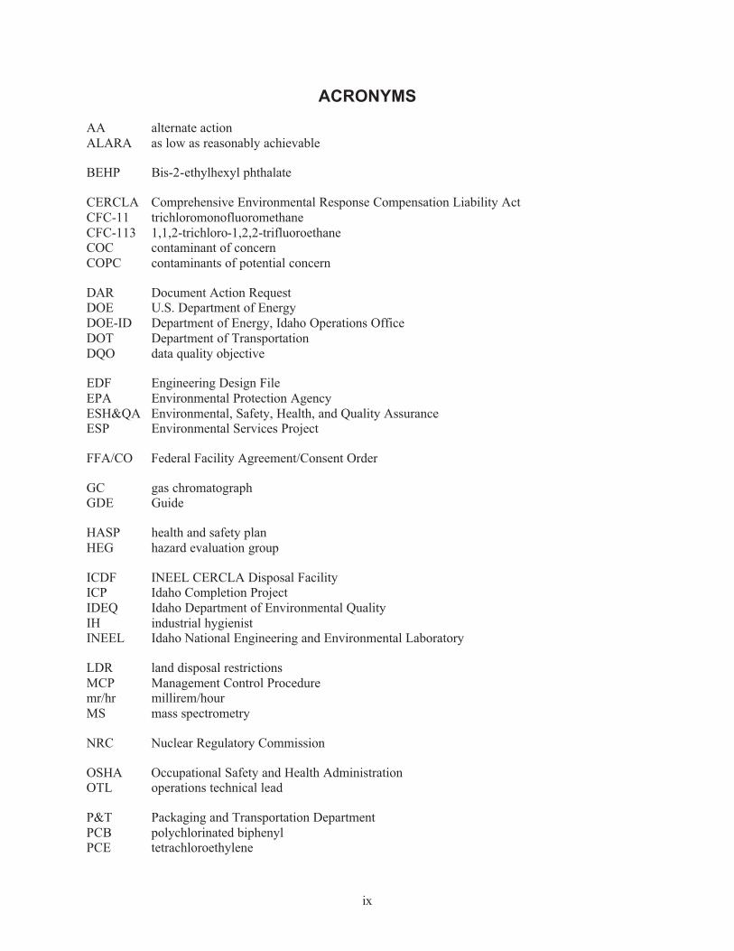
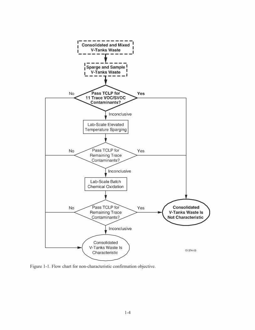
In support of the non-characteristic confirmation objective, plans are to perform a toxicity characteristic leaching procedure (TCLP) analysis for hazardous metals, volatile organic compounds
(VOCs), and semivolatile organic compounds (SVOCs) on the consolidated waste stream after sparging
operations have been completed. This shall be done using standard analytical methods. Additional analyses or treatments on the consolidated waste will be performed, if necessary, to confirm the non-
characteristic nature of the waste for the eleven trace organic constituents identified in EDF-4885. A
summary flow chart for the non-characteristic waste confirmation objective, applied to the eleven trace organic constituents, is shown in Figure 1-1. The flow chart was prepared based upon discussions with
the IDEQ. The agreed-upon approach was to remove the contaminants interfering with the analytical
determination of the eleven trace contaminants that had previously been identified as inconclusive.
Samples collected after the consolidated waste is sparged will be tested. If results are still inconclusive, lab-scale sparging at elevated temperatures (up to and including boiling) and/or chemical oxidation will
be conducted to attempt to remove or destroy the interfering contaminants. Results from such studies will
help define the conditions for batch processing of the waste as part of Phase 2 treatment (if Phase 2 treatment is required).
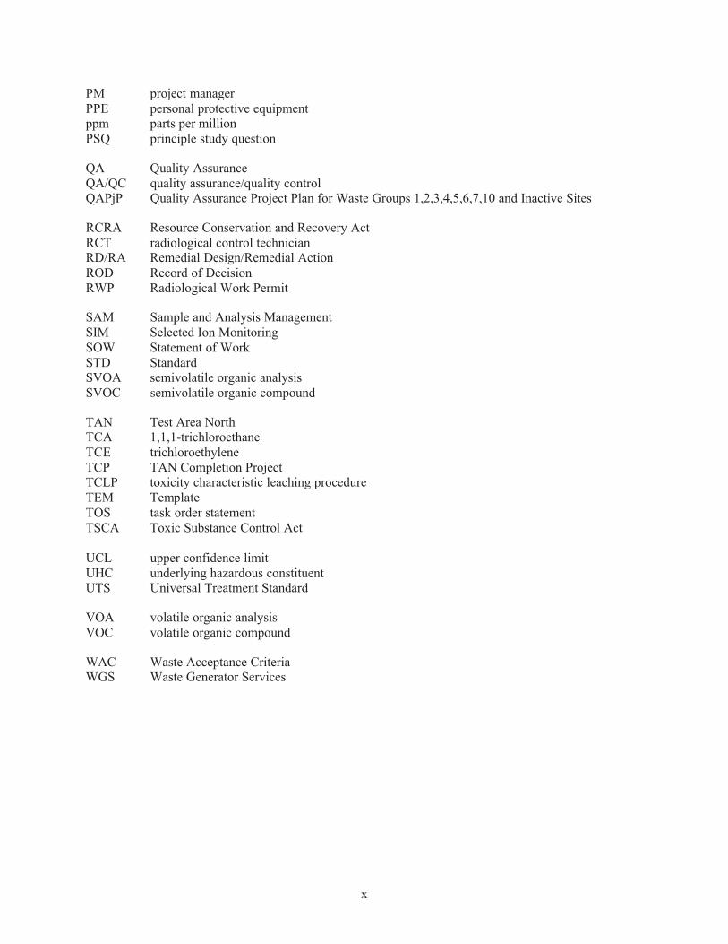
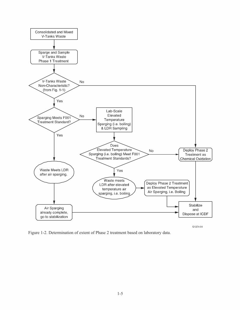
A summary flow chart for the Phase 1 treatment evaluation objective is shown in Figure 1-2. The
figure shows the process for determining whether or not additional Phase 2 treatment will be required
1-3
prior to solidification. If additional treatment is required, a secondary objective will be to determine the
initial details of Phase 2 treatment.
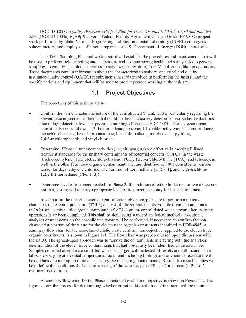
A schematic showing the V-tank Phase 1 treatment process, in combination with tank consolidation
activities, is shown in Figure 1-3.
1-4
Figure 1-1. Flow chart for non-characteristic confirmation objective.
1-5
Figure 1-2. Determination of extent of Phase 2 treatment based on laboratory data.

1-6
Figure 1-3. Process schematic for tank consolidation and Phase 1 treatment.
1.2 Site and Waste Description
The site description of the Idaho National Engineering and Environmental Laboratory (INEEL) is
provided in the QAPjP referenced in Section 1. The description of Test Area North (TAN) is also
provided in the referenced QAPjP.
Test Area North is located at the north end of the INEEL, about 27 miles northeast of the Central
Facilities Area. TAN was established in the 1950s by the U.S. Air Force and Atomic Energy Commission
Aircraft Nuclear Propulsion Program to support nuclear-powered aircraft research. Upon termination of
this research, the area's facilities were converted to support a variety of other DOE research projects. Today, TAN is composed of the Contained Test Facility (inactive) and the Technical Support Facility.
The V-tanks are being remediated as part of a Comprehensive Environmental Response
Compensation Liability Act (CERCLA) response action covered by the Federal Facility Agreement/Consent Order (FFA/CO). This document is being prepared in support of the V-tanks Record
of Decision (ROD) Amendment and Explanation of Significant Differences (DOE, EPA, IDEQ 2004).
The V-tanks are designated as INEEL CERCLA sites TSF-09 and TSF-18. These tanks were part
of the Intermediate Level Radioactive Waste Management System at TAN (see Figure 1-3). The V-tanks include three l0,000-gal (37,850-L) underground storage tanks (Tanks V-1, V-2, and V-3) and one
400-gal (1,514-L) underground storage tank (Tank V-9).
After consolidating the V-tanks’ waste into new consolidation tanks, additional minor volumes of similar wastes will be introduced into the consolidated waste stream (minor volumes of water may be
used for rinsing containers). These minor waste streams and their volumes are:
1-7
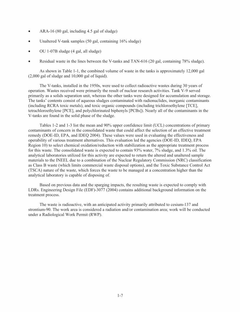
• ARA-16 (80 gal, including 4.5 gal of sludge)
• Unaltered V-tank samples (50 gal, containing 16% sludge)
• OU 1-07B sludge (4 gal, all sludge)
• Residual waste in the lines between the V-tanks and TAN-616 (20 gal, containing 78% sludge).
As shown in Table 1-1, the combined volume of waste in the tanks is approximately 12,000 gal
(2,000 gal of sludge and 10,000 gal of liquid).
The V-tanks, installed in the 1950s, were used to collect radioactive wastes during 30 years of
operation. Wastes received were primarily the result of nuclear research activities. Tank V-9 served
primarily as a solids separation unit, whereas the other tanks were designed for accumulation and storage. The tanks’ contents consist of aqueous sludges contaminated with radionuclides, inorganic contaminants
(including RCRA toxic metals), and toxic organic compounds (including trichloroethylene [TCE],
tetrachloroethylene [PCE], and polychlorinated biphenyls [PCBs]). Nearly all of the contaminants in the
V-tanks are found in the solid phase of the sludge.
Tables 1-2 and 1-3 list the mean and 90% upper confidence limit (UCL) concentrations of primary
contaminants of concern in the consolidated waste that could affect the selection of an effective treatment
remedy (DOE-ID, EPA, and IDEQ 2004). These values were used in evaluating the effectiveness and operability of various treatment alternatives. This evaluation led the agencies (DOE-ID, IDEQ, EPA
Region 10) to select chemical oxidation/reduction with stabilization as the appropriate treatment process
for this waste. The consolidated waste is expected to contain 93% water, 7% sludge, and 1.3% oil. The
analytical laboratories utilized for this activity are expected to return the altered and unaltered sample materials to the INEEL due to a combination of the Nuclear Regulatory Commission (NRC) classification
as Class B waste (which limits commercial waste disposal options), and the Toxic Substance Control Act
(TSCA) nature of the waste, which forces the waste to be managed at a concentration higher than the analytical laboratory is capable of disposing of.
Based on previous data and the sparging impacts, the resulting waste is expected to comply with
LDRs. Engineering Design File (EDF)-3077 (2004) contains additional background information on the treatment process.
The waste is radioactive, with an anticipated activity primarily attributed to cesium-137 and
strontium-90. The work area is considered a radiation and/or contamination area; work will be conducted
under a Radiological Work Permit (RWP).

1-8
Table 1-1. Consolidated waste volume contents (data rounded).
Tank
Liquid (gal)
Sludge (gal)
Total (gal)
V-1 1,160 520 1,680
V-2 1,140 460 1,600
V-3 7,660 650 8,310
V-9 70 250 320
ARA-16 75.5 4.5 80
Unaltered V-Tank Samples 42.1 7.9 50
OU 1-07B 0 4 4
V-Tanks to TAN-616 Lines Waste 4.4 15.6 20
Total 10,152 1,912 12,064
Source: EDF-4928, “Potential Feed Streams for Inclusion into V-tank Treatment Process,” 2004.
Table 1-2. Major contaminants of concern in the consolidated waste.
Constituent
Mean Concentration (mg/kg)
90% UCLa Concentration
(mg/kg)
Antimony 0.917 1.56
Arsenic 0.365 0.52
Barium 12.9 24.6
Beryllium 1.14 1.42
Cadmium 2.37 2.85
Chlorides 108 128
Chromium 299 384
Lead 37.0 43.6
Mercury 81.5 96.7
Nickel 16.9 20.9
Silver 19.2 20.4
Tetrachloroethylene (PCE) 118 176
1, 1, 1-Trichloroethane (TCA) 64.3 126
Trichloroethylene (TCE) 451 767
Bis-2-ethylhexyl phthalate (BEHP) 451 525
Aroclor-1260 (a PCB) 18.0 21.0
Toluene 6.49 16.6
Source: EDF-4928, “Potential Feed Streams for Inclusion into V-tank Treatment Process,” 2004.
a. UCL—upper confidence limit.

1-9
Table 1-3. Radionuclide content in the consolidated waste.
Radionuclide
Mean Concentration (nCi/g)
90% UCL a
Concentration (mg/kg)
Cesium-137 992 1,180
Strontium-90 1,840 2,360
Transuranics 4.34 5.56
Source: EDF-4928, “Potential Feed Streams for Inclusion into V-tank Treatment Process,” 2004.
a. UCL—upper confidence limit.
2-1
2. PROJECT ORGANIZATION AND RESPONSIBILITIES
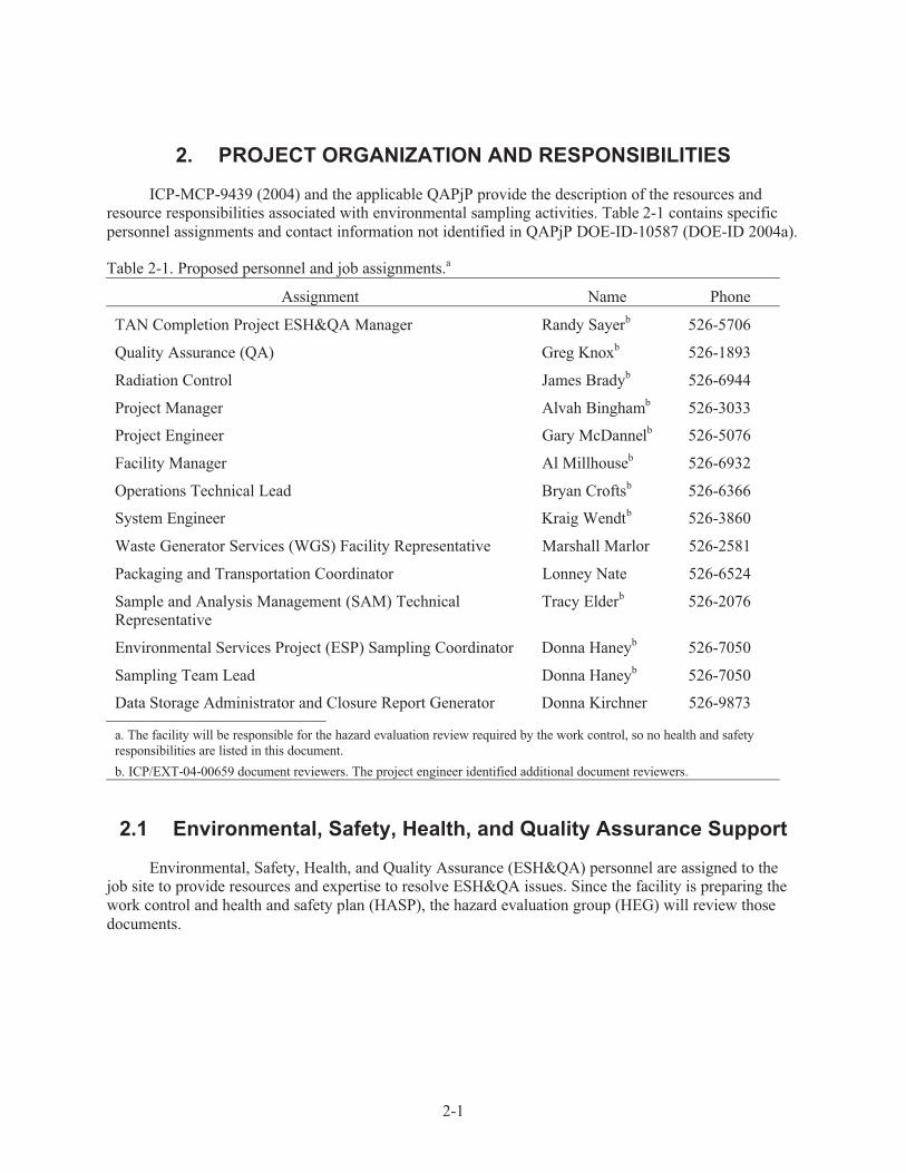
ICP-MCP-9439 (2004) and the applicable QAPjP provide the description of the resources and resource responsibilities associated with environmental sampling activities. Table 2-1 contains specific
personnel assignments and contact information not identified in QAPjP DOE-ID-10587 (DOE-ID 2004a).
Table 2-1. Proposed personnel and job assignments.a
Assignment Name Phone
TAN Completion Project ESH&QA Manager
Quality Assurance (QA)
Radiation Control
Randy Sayerb
Greg Knoxb
James Bradyb
526-5706
526-1893
526-6944
Project Manager Alvah Binghamb 526-3033
Project Engineer Gary McDannelb 526-5076
Facility Manager Al Millhouseb 526-6932
Operations Technical Lead Bryan Croftsb 526-6366
System Engineer Kraig Wendtb 526-3860
Waste Generator Services (WGS) Facility Representative Marshall Marlor 526-2581
Packaging and Transportation Coordinator Lonney Nate 526-6524
Sample and Analysis Management (SAM) Technical Representative
Tracy Elderb 526-2076
Environmental Services Project (ESP) Sampling Coordinator Donna Haneyb 526-7050
Sampling Team Lead Donna Haneyb 526-7050
Data Storage Administrator and Closure Report Generator Donna Kirchner 526-9873
a. The facility will be responsible for the hazard evaluation review required by the work control, so no health and safety
responsibilities are listed in this document.
b. ICP/EXT-04-00659 document reviewers. The project engineer identified additional document reviewers.
2.1 Environmental, Safety, Health, and Quality Assurance Support
Environmental, Safety, Health, and Quality Assurance (ESH&QA) personnel are assigned to the job site to provide resources and expertise to resolve ESH&QA issues. Since the facility is preparing the
work control and health and safety plan (HASP), the hazard evaluation group (HEG) will review those
documents.

2-2
2.2 TAN Completion Project Environmental Safety, Health, and Quality Assurance Manager
The TAN Completion Project (TCP) Environmental Safety, Health, and Quality Assurance
(ESH&QA) manager or designee reports directly to the TCP director and is responsible for managing
ESH&QA resources, including:
• Ensuring that ESH&QA programs, policies, standards, procedures, and mandatory requirements
are planned, scheduled, implemented, and executed in the day-to-day TCP operations
• Directing ESH&QA compliance in all activities by coordinating related functional entities and
providing technical and administrative direction to subordinate staff.
Under the direction of the TCP director, the TCP ESH&QA manager represents the TCP directorate in all ESH&QA matters and is responsible for:
• TCP ESH&QA management compliance
• Oversight for all TCP CERCLA operations planned and conducted at Waste Area Group 1
• TCP INEEL-wide environmental monitoring activities.
The TCP ESH&QA manager directs the management of personnel and the implementation of
programs related to the following technical disciplines:
• Industrial safety
• Fire protection
• QA
• Industrial hygiene (IH) (matrixed)
• Emergency preparedness (matrixed)
• Radiation control
• Criticality safety (matrixed).
All ESH&QA activities associated with Phase 1 treatment sampling will be coordinated with the
ESH&QA manager to make certain functional safety, quality, and environmental management are
properly contacted per guidelines of the HASP.
2.3 Quality Assurance
Quality Assurance personnel will be responsible for reviewing both the health and safety documentation and this sampling plan to assess and ensure compliance with applicable INEEL
procedures, including this document, at a Quality Level 4.
2-3
2.4 Radiation Control
Because of the radioactive nature of the consolidated waste, all sampling activities (including waste
packaging) will have to be under appropriate radiation controls. Primary responsibilities associated with Radiation Control include the following:
• Assisting in design of the sampling station to ensure that the as low as reasonably achievable
(ALARA) principles are being considered and that sampling personnel will not be exposed to
radiation levels outside of administrative controls
• Monitoring the radiation levels and degree of sampling exposure experienced by sampling
personnel during all phases of the sampling operation (sampling, sample storage, and sample packaging and transport)
• Monitoring the packaging of the sample containers to verify they are within P&T guidelines.
Radiation Control will work with both the sampling team lead and the operations technical lead to
ensure that the sampling operation will be conducted without spreading radioactive contamination and without exposing the sampling team to unnecessary radiation.
2.5 Project Manager/Facility Manager
The project manager (PM) and facility manager ensure that all activities conducted during the
project comply with INEEL management control procedures, program requirements documents, and all
applicable requirements of the Occupational Safety and Health Administration (OSHA), Environmental Protection Agency (EPA), U.S. Department of Energy (DOE), U.S. Department of Transportation (DOT),
and the State of Idaho. The PM coordinates all document preparation, field and laboratory activities, data
evaluation, risk assessment, dose assessment, and design activities. The PM is responsible for the overall work scope, schedule, and budget.
The PM is responsible for field activities and for all personnel (including craft personnel) assigned
to work at the project location. The PM serves as the interface between operations and project personnel
and works closely with the sampling team at the site to ensure that the objectives of the project are accomplished in a safe and efficient manner. The PM works with all other identified project personnel to
accomplish day-to-day operations, identify and obtain additional resources needed at the site, and interact
with ESH&QA oversight personnel on matters regarding health and safety.
The facility manager ensures that all work is performed in compliance with facility-specific
requirements and that workers are aware of any health and safety hazards that may affect the job.
2.6 Project Engineer
The project engineer is ultimately responsible for all technical activities associated with Phase 1
design decisions on the consolidated V-tank waste. As such, he is responsible for making the major technical decisions associated with the V-tank sampling effort. Such decisions include determining
whether the results of the air-sparged samples are sufficient to support the non-characteristic confirmation
and F-listed treatment standards for the waste or if additional treatment activities are required. He is also available to confirm with the system engineer on determining when both air-sparging and tank
cross-mixing activities can be considered complete prior to initiating Phase 1 treatment sampling

2-4
activities. The project engineer will also be responsible for all other project decisions made as a result of
this sampling activity.
2.7 Operations Technical Lead
The operations technical lead (OTL) has ultimate responsibility for the safe and successful
completion of activities associated with Phase 1 waste treatment activities (air-sparging and cross-mixing
of the sparged tank wastes prior to sampling). This includes control of the Operating Area during Phase 1
treatment sampling operations. All health and safety issues at the V-tank site for this work must be brought to the OTL’s attention. In addition to managing field operations, work control during Field
Sampling Plan execution (as applicable), enforcing site control, documenting work site activities, and
conducting daily safety briefings, the OTL’s responsibilities include, but are not limited to the following:
• Enforcing task-site control, documenting activities, and conducting project-specific plan-of-the-day
meetings and daily safety briefings at the start of each shift
• Completing briefings and reviews in accordance with MCP-3003, “Performing Pre-Job Briefings
and Post-Job Reviews”
• Completing the job requirements checklist in accordance with Standard (STD)-101, “Integrated
Work Control Process”
• Managing emergency and accident response and coordination
• Conducting ESH&QA inspections
• Ensuring compliance with waste management requirements and coordinating such activities with
the environmental compliance coordinator or designee.
2.8 System Engineer
The system engineer is responsible for all technical decisions associated with V-tank remediation
operations. This includes decisions regarding when air-sparging activities can be considered complete for
each tank, if and when to conduct periodic off-gas monitoring (to ascertain the completion of air-sparging activities for each tank), when to initiate cross-mixing activities on the sparged tank volumes (prior to
Phase 1 treatment sampling), and when to allow Phase 1 treatment sampling to proceed (the project
engineer can assist the system engineer in these decisions). The system engineer is also responsible for general oversight on all activities associated with V-tank operations.
2.9 Waste Generator Services Facility Representative
The INEEL Waste Generator Services (WGS) facility representative will ensure disposition of
waste material complies with approved INEEL waste management procedures. WGS personnel have the
responsibility to help solve waste management issues at the task site. WGS personnel also prepare the appropriate documentation for waste disposal and make the required notifications. All wastes will be
disposed of using approved INEEL procedures in accordance with INEEL MCP-3472, “Identification and
Characterization of Environmentally Regulated Waste” (1999). The unaltered and altered samples will be reincorporated into the bulk V-tank wastes prior to stabilization.

2-5
2.10 Packaging and Transportation Coordinator
The Packaging and Transportation coordinator shall be responsible for ensuring that the collected
samples are packaged and shipped to the appropriate analytical laboratory in accordance with DOT guidelines and for receiving sample media returned from the laboratory.
2.11 Sample and Analysis Management Technical Representative
The Sample and Analysis Management (SAM) technical representative is responsible to help
define the analytical project, generate the sampling and analysis plan table, and generate and issue sample
labels. The SAM representative determines which laboratory will provide analytical services based on established policies and contracts, and prepares the task order statement(s) (TOS). The SAM
representative also tracks analytical progress and performs cursory review of the final data packages. The
SAM representative will obtain independent validation of the data results as project requirements dictate.
2.12 Environmental Services Project Sampling Coordinator
The Environmental Services Project (ESP) sampling coordinator is responsible for coordinating sampling activities applicable to this project. Upon notification by the project manager, the sampling
coordinator is responsible for obtaining and scheduling the necessary resources to complete the sampling
task. The sampling coordinator will schedule sampling personnel to complete the task. The sampling coordinator is also responsible for managing and obtaining sampling supplies and tools to complete the
task, if needed.
2.13 Sampling Team Lead
An ESP representative will be the sampling team lead for the sampling task and will perform the
pre-job briefing and oversee sampling documentation and performance of the associated sampling activities. ESP sampling team lead activities usually include reviewing the request for sampling, walking
down the job site, issuing a sampling plan, notifying the SAM to procure laboratories, ensuring that all
required reviews and approvals are obtained on the sampling documentation, coordinating purchasing the equipment necessary to perform the job, and performing the pre-job briefing. ESP will maintain a project
file until the project is complete and then turn it over to the data storage administrator.
2.14 Data Storage Administrator and Closure Report Generator
The data are tracked through the SAM. When data are received at the SAM, they are sent to ESP
for interpretation and issuance of a closure report to the project manager. The data storage administrator is responsible for maintenance of data records. The final project file will be scanned into the Electronic
Document Management System.

3-1
3. DATA QUALITY OBJECTIVES
Data quality objectives (DQOs) are qualitative and quantitative statements derived from the first six steps of the Environmental Protection Agency’s (EPA’s) DQO process (Guidance for the Data
Quality Objective Process [EPA 2000]) and are summarized in the applicable project QAPjP referenced
in Section 1 (Quality Assurance Project Plan for Waste Groups 1,2,3,4,5,6,7,10 and Inactive Sites
[DOE-ID 2004a]).
3.1 Problem Statement
The first problem statement is to determine whether or not the previous non-characteristic
designation for the consolidated V-tank waste was correct. This will be performed via toxicity
characteristic leaching procedure-volatile organic compound (TCLP-VOC), TCLP-semivolatile organic compound (SVOC), and TCLP-metals analysis of samples of the sparged waste. Of particular emphasis is
the need to verify the non-characteristic nature of eleven trace TCLP constituents (four VOCs and seven
SVOCs). Air sparging is expected to eliminate most of the interferences in the samples that were causing
detection levels that were higher than the regulatory levels. More sensitive analytical methods may be used to provide a conclusive determination for these eleven trace organic constituents, if necessary.
Additional treatment conditions may also have to be performed (such as elevated temperature
sparging/boiling or chemical oxidation) to remove additional contaminant interference sufficient to allow for a conclusive determination as to the non-characteristic or characteristic nature of these eleven trace
organic constituents. This is in accordance with agreements by the agencies (DOE-ID, IDEQ, EPA
Region 10) on how to proceed should inconclusive data still be generated. Additional treatment should
only be performed as a last resort, after all other conditions have been attempted (including the use of more sensitive analytical methods).
The second problem statement is to determine if the air-sparging activity provides sufficient
treatment of the organics to proceed toward direct solidification and disposal without additional treatment (i.e., elevated temperature sparging or chemical oxidation). This will be performed via total-VOC analysis
on all F-listed contaminants of concern (all identified F001 constituents, plus toluene) in the sparged tank
waste samples. The treated waste (if non-characteristically hazardous) must meet the F-listed treatment standards for these organics before it can be disposed of at the ICDF. However, the increase in weight
associated with the addition of solidification agents (along with the resulting decrease in concentration
associated with such a weight addition) can be considered in determining compliance to the F-listed
treatment standards. Therefore, the resulting concentration of F-listed constituents in the air-sparged waste only has to be at a level low enough that the treatment standard for the F-listed constituents would
be met following solidification.
The third problem statement is to determine the extent of treatment needed in Phase 2 treatment if the waste is characteristically hazardous or if sparging at ambient temperatures does not meet the F-listed
treatment standards.
Any required verification sampling after characterization and stabilization will be performed under separate work control. The planning team and available resource members are identified in Section 2. The
decision-maker for the activity is the project manager. Preliminary data from the air-sparge samples must
be received by January 31, 2005. Validated analytical data are required by February 28, 2005.

3-2
3.2 Decision Statement
The non-characteristic determination must be performed to complete Resource Conservation and
Recovery Act/Toxic Substance Control Act (RCRA/TSCA) hazardous waste determination and to demonstrate that the V-tank waste meets or does not meet the ICDF Waste Acceptance Criteria (WAC).
The leaching procedure shall be in accordance with standard TCLP methods (SW-846 [EPA 1986]
Method 1831). The analyses will follow standard analytical procedures (SW-846 Method 8260B for
VOCs, 8270C for SVOCs, 6010B for metals, and 7470A for mercury). Further Select Ion Monitoring (SIM) analysis (Section 7.5.12 of 8260B for VOCs, Section 7.5.5 of 8270C for SVOCs) will be
performed on each prepared sample immediately following standard analyses, if necessary, to
conclusively determine actual concentrations for the eleven trace organic D-list constituents identified in EDF-4885, as well as the eight F-listed organic contaminants needing to be treated prior to stabilization.
If even higher resolution equipment is required, the analyses shall be performed using the same sample
preparations that were previously prepared but will involve either the high-resolution gas chromatograph
(GC)/low-resolution mass spectrometry (MS) equipment described in Method 8280 or the high-resolution GC/high-resolution MS equipment described in Method 8290 for those trace organic constituents still
inconclusive following SIM analysis. No additional sample volume will be taken for the higher resolution
analytical methods since the sample preparation will be the same for all analyses and the analyses only use a small portion of the prepared sample volume.
The objective(s) of this non-characteristic determination effort is to answer the following question:
• Does the consolidated TAN V-tank waste contain hazardous concentrations of TCLP-metals,
TCLP-VOCs, or TCLP-SVOCs, with particular emphasis on the eleven trace RCRA constituents identified in EDF-4885 (2004)? The eleven trace RCRA constituents of concern (COC), their
D-codes, and release limits are shown in Table 3-1.
Table 3-1. Contaminants of concern, D-codes, and regulatory limits.
TCLP Contaminant of Concern D-Code Regulatory Limit
1,2-Dichloroethane D028 0.5 mg/L
Benzene D018 0.5 mg/L
1,1-Dichloroethylene D029 0.7 mg/L
2,4-Dinitrotoluene D030 0.13 mg/L
Hexachlorobenzene D032 0.13 mg/L
Hexachlorobutadiene D033 0.5 mg/L
Hexachloroethane D034 3.0 mg/L
Nitrobenzene D036 2.0 mg/L
Pyridine D038 5.0 mg/L
2,4,6-Trichlorophenol D042 2.0 mg/L
Vinyl chloride D043 0.2 mg/L

3-3
The alternate actions (AAs) to be taken, depending on the resolution of the principal study
question(s) (PSQ)(s), are as follows:
• If the materials are determined to be non-characteristic (they can be TSCA hazardous or
radioactive), they may be disposed of at the ICDF after solidification provided they meet F-listed
treatment standards for all F001 constituents and toluene following solidification.
• If they are determined to be characteristic, the waste must be treated to meet both F-listed treatment
standards, as well as underlying hazardous constituent (UHC) Universal Treatment Standards
(UTSs) and will require chemical oxidation as part of Phase 2 treatment to meet the ICDF disposal requirements. This Field Sampling Plan does not address Phase 2 activities.
• If sample results show that the waste is non-characteristic but that sparging in combination with
solidification does not meet the F-listed treatment standards, then the waste must undergo Phase 2
treatment to meet ICDF disposal requirements. However, UHC UTSs do not need to be met by Phase 2 treatment under this condition. This Field Sampling Plan does not address Phase 2
activities.
Process requirements associated with these objectives are as follows:
• Mix waste in consolidation tanks sufficiently to produce representative samples from single sample
location (see mixing calculation Appendix B).
• Ensure appropriate analytical methods (with high resolution equipment as necessary) are used for
the eleven targeted trace organic contaminants of concern (see Table 3-1) such that detection limits
are sufficiently below regulatory levels, such that a 90% UCL estimate, using detection levels as
actual leachate concentrations, would still be below the regulatory levels for each constituent of concern. This will prevent inconclusive results that limit the project’s ability to defensively
determine when treatment is complete and the waste is acceptable for disposal.
• If lab-scale elevated temperature sparging/boiling or chemical oxidation activities are performed as
part of the determination of the extent of Phase 2 treatment, they should be performed under conditions expected to represent actual Phase 2 conditions.
Combining the PSQ and AAs results in the following decision statements:
• Does the consolidated V-tank waste pass TCLP for all D-listed VOCs, SVOCs, and metals (with
particular emphasis on the eleven trace D-list constituents discussed in Decision Statement 1)? (see Figure 1-1.)
• Does air-sparging of the consolidated V-tank waste result in organic concentrations in the waste
that meet nonwastewater treatment standards for the eight F-listed constituents listed in Table 3-2
following waste solidification? (see Figure 1-2.)

3-4
Table 3-2. F-listed constituents of concern and their treatment standards.
F-Listed Constituent Treatment Standard
Tetrachloroethylene (PCE) 6.0 mg/kg
Trichloroethylene (TCE) 6.0 mg/kg
Methylene chloride 30 mg/kg
1,1,1-Trichloroethane (TCA) 6.0 mg/kg
Carbon tetrachloride 6.0 mg/kg
1,1,2-Trichloro-1,2,2-trifluoromethane (CFC-113) 30 mg/kg
Trichloromonofluoromethane (CFC-11) 30 mg/kg
Toluene 10 mg/kg
• If sparging at ambient temperatures is insufficient to meet F-listed treatment standards, what is the
extent of Phase 2 treatment necessary to meet LDR treatment standards and ICDF WAC?
3.3 Decision Inputs
To resolve the decision statements, concentrations of the constituents of concern must be obtained using approved analytical methods. The constituents of concern in the V-tank waste include:
• Analyses of TCLP leachates for all D-listed metals, VOCs, and SVOCs, using standard analytical
methods
• SIM-analyzed TCLP leachates for four RCRA volatile organic compounds and seven RCRA
semivolatile organic compounds, if necessary (with even more sensitive analytical methods, if
necessary)
• Total concentrations of F-listed constituents in the waste (using SIM analysis or even more
sensitive analytical methods, if necessary).
The project reviewed past data and necessary detection limits to select the contaminants of concern and
associated analytical methods for this sampling investigation (Section 3.2).
3.4 Study Boundaries
The spatial boundary of the study is a well mixed consolidated waste stream contained within two
8,000-gallon tanks. Access to recirculated liquids will be from a single low-point drain valve located in
the recirculation lines between the cross-mixed tanks. The valve, including control of the flow rate, will
be tested prior to sampling. There is no reason to believe that the valve will physically limit access to the waste. The valve will be purged prior to sample collection to remove any stagnant material. Premixing
between sparged tanks prior to sampling and continuous cross-mixing during sampling is required to
ensure representative samples from the single sample valve.
Calculations performed in support of this requirement have determined that a mixing time of at
least 11 hours is recommended (8 hours is required) before consolidated waste sampling can proceed. The
calculation is based on assumptions that the maximum volume of waste in each consolidation tank is less than 7,200 gal and that the rate of mixing between tanks is greater than 50 gal/min. The results from the

3-5
calculation suggest that the concentrations in each of these tanks, after 8 hours of mixing, will differ by
less than 0.5% (see Appendix B).
The temporal boundaries of the study are the target dates defined in Section 3.1.
Limitations on data interpretation introduced by sample collection constraints, if applicable, will be
brought immediately to the project manager’s attention and discussed in the project final report.
3.5 Decision Rule
If the waste is non-characteristic and F-listed treatment standards have been met after sparging, the waste can be solidified and disposed of at the ICDF without additional Phase 2 treatment.
If the waste is non-characteristic and F-listed treatment standards have not been met after sparging,
lab-scale elevated temperature sparging will be conducted to determine the extent of Phase 2 treatment necessary.
a
If the TCLP leachate concentrations of RCRA volatile organic analyses (VOAs) and semivolatile
organic analysis (SVOAs) exceed characteristic levels, then chemical oxidation will be required for Phase
2 treatment.a
Figure 3-1 is a flow diagram showing the decisions to be made by the Phase 1 treatment sampling
activity.
3.6 Decision Error Limits
Two types of decision errors have been identified in this sampling design. The first is that the analyzed waste may be determined to not contain hazardous constituents above regulatory limits, when in
fact, they do, and the second is that the waste may be determined to contain hazardous constituents above
regulatory limits, when, in fact, they do not. The consequences of each decision error are discussed
below.
Determining that the consolidated waste stream is not RCRA characteristic or does meet the
treatment standard, when in fact, the waste is RCRA characteristic or fails to meet the treatment standard,
would result in the consolidated waste stream not receiving appropriate treatment. This may result in CERCLA compliance issues and failure to protect human health and the environment. This wrong
decision is generally referred to as a Type I error or a false positive error.
Determining that the consolidated waste stream is RCRA characteristic or does not meet the treatment standard, when in fact, the waste is not RCRA characteristic or meets the treatment standard,
would result in further expense of project resources to complete unnecessary activities (i.e., Phase 2
treatment). This wrong decision is generally referred to as a Type II error or a false negative error.
The Field Sampling Plan recommends a minimum confidence level of 90% for Type I errors (false-positive), and the minimum complement of the power is 80% for the Type II errors (false negative).
The 90% level was established based upon EPA in SW-846 guidance for determining compliance with
concentration-based requirements.
a. Phase 2 treatment will be described in Addendum 3 of the RD/RA Work Plan (DOE, EPA, IDEQ 2004), as necessary.

3-6
3.7 Design Optimization
The sample design chosen for the TAN V-tanks’ waste is based on the approach designed to
provide representative data. Samples that are representative of the material being characterized will be obtained by collecting grab samples off a valve. However, the design and presampling process used to
homogenize all tank contents (i.e., 8–11 hrs of cross-mixing between tanks, following air-sparging)
results in inherently composited samples. Refer to Appendix B, which shows the project’s calculations for
required mixing time for optimum sample representativeness. In addition, procedures will be in place (via work packages) to flush the potential “dead space” portions of the recirculatory line (where premixing
may not have had any effect) prior to initiating sampling and following each sample set. Finally, the
Phase 1 treatment sampling will be conducted with the air-sparging activity temporarily discontinued to eliminate concerns associated with the randomness of the sample data (due to continually lower
concentrations of VOCs if air-sparging were to continue and the time between sample collections were
accidentally prolonged).
The sample sets will be collected sequentially, with no expected downtime between sets, with the exception of shutting off the valve between samples and flushing the sample line between sample sets.
After any unforeseen downtime (such as for sample equipment maintenance or transporting the sample
bottles out of the containment area) and before resuming sampling, the sample line will be flushed.

3-7
Figure 3-1. Flow diagram for the Phase 1 treatment sampling decisions.

4-1
4. SAMPLE COLLECTION, ANALYSIS, AND DATA MANAGEMENT
4.1 Sample Collection
4.1.1 Pre-Sampling Meeting
Before the start of each field-sampling project, ESP-assigned sampling resources prepare for the sampling activity in accordance with MCP-9228, “Environmental Sample Management” (2004), and
participate in applicable pre-job briefings conducted in accordance with MCP-3003, “Performing Pre-Job
Briefings and Documenting Feedback” (2003). Personnel at the meeting will ensure that all necessary equipment and documentation are present and that all personnel understand the project scope and
objectives.
4.1.2 Sampling and Analysis Requirements
Radiological engineering will determine how the sample valve access will be controlled and how
sample material will be contained to prevent contamination spread to the surrounding environment. The
specifics regarding the health and safety aspects of sampling will be covered under facility work control
(in accordance with the HASP). Project personnel have determined that a suite of samples for the contaminants of concern will be collected in triplicate, and trip blanks of water will also be sent to
evaluate VOC cross contamination between samples. Such sampling is sufficient to provide a 90%
confidence level for the resulting data. Replicate samples are taken to show data comparability, while trip blanks are collected to show any interference introduced during transport. The same level of triplicate
analysis will also be provided for each type of analysis that is undertaken (if more sensitive analytical
methods are required), as well as for each additional treatment condition (i.e., boiling or chemical
oxidation) that must be performed (if additional treatment conditions are required).
Only four types of analyses are required for Phase 1 treatment sampling activities:
• TCLP-VOAs
• TCLP-SVOAs
• TCLP-metals
• Total VOAs.
The TCLP-VOA, TCLP-SVOA, and TCLP-metals analyses are needed to confirm the non-characteristic
designation of the consolidated waste stream, while the total VOA analysis is needed to determine if air-sparging treats the consolidated waste sufficiently that all applicable F-listed treatment standards can
be met by simply stabilizing the waste, without additional pretreatment such as chemical oxidation. If
results from the air-sparge samples show that treatment standards cannot be met by air-sparging and solidification or if the waste is found to be characteristically hazardous, then additional analyses will be
performed following elevated temperature sparging/boiling and/or chemical oxidation of the laboratory
samples to determine the degree of Phase 2 treatment that will be required.
The agencies (DOE-ID, IDEQ, EPA Region 10) identified the degree of PCB volatilization during treatment as a concern that still must be addressed during V-tank remediation. The best method to address
PCB volatilization is to evaluate the concentration of PCBs in the granular activated carbon (GAC) filter

4-2
as part of the secondary waste disposition following treatment. Such analysis will be requested of Waste
Generator Services at the time of secondary waste disposition.
The SAM representative is responsible for coordinating sampling activities with the laboratory and
preparing a sampling and analysis plan table (Appendix A), field guidance forms, and the associated
sample labels. The laboratory is aware of the anticipated levels of activity and has specified minimum
sample volumes (see Table 4-1) to be submitted for analysis to ensure compliance with their Nuclear Regulatory Commission (NRC) license and other regulatory drivers.
The complex sampling strategy is due to additional analyses that may be required if the initial
non-characteristic confirmation is inconclusive or the F-listed treatment standards have not been met by air-sparging. If the initial non-characteristic confirmation is inconclusive, the samples must be subjected
to additional pretreatment options to try to remove the interferences from the waste prior to re-analysis.
Such additional pretreatment options include both elevated temperature sparging/boiling and oxidation. It is recognized that such additional treatment activities may also be removing the trace contaminants from
the waste. For this reason, the additional treatment activities associated with the non-characteristic
confirmation should only be performed after all attempts have been made to obtain conclusive results in
the initial analysis. For this reason, the most sensitive types of organic analyses should be used on the targeted organic constituents identified in Tables 3-1 and 3-2, if appropriate (see Section 3.2 for details).
Additional sample material will be needed if such measures produce inconclusive results. If the results
from Phase 1 treatment show that air-sparging did not reduce F-listed constituents to less than treatment standards (following solidification), then additional sample material will be used in lab-scale studies to
define the extent of Phase 2 treatment that will be required. All analyses, except for TCLP-metals, have
the potential of being performed under boiling and/or chemical oxidation conditions, in addition to the air-sparged condition.
For this reason, the volume and amount of sample material needed for triplicate analysis of
TCLP-metals, TCLP-VOAs, TCLP-SVOAs, and total VOAs were carefully identified and documented in
Table 4-1. The documentation is performed by determining the minimum amount of sample material required for each analysis and multiplying it by the number of conditions or analyses that may need to be
performed. Included in each determination are any special considerations that might be required, such as
the need for matrix spikes and matrix spike duplicates, the identification of triplicate volumes for at least one of the triplicate analyses per condition, and potential issues associated with providing additional
samples if sample bottles break. In addition, the sample determination must be made while limiting the
maximum volume of each sample to less than 1 L total volume (because of container limitations).
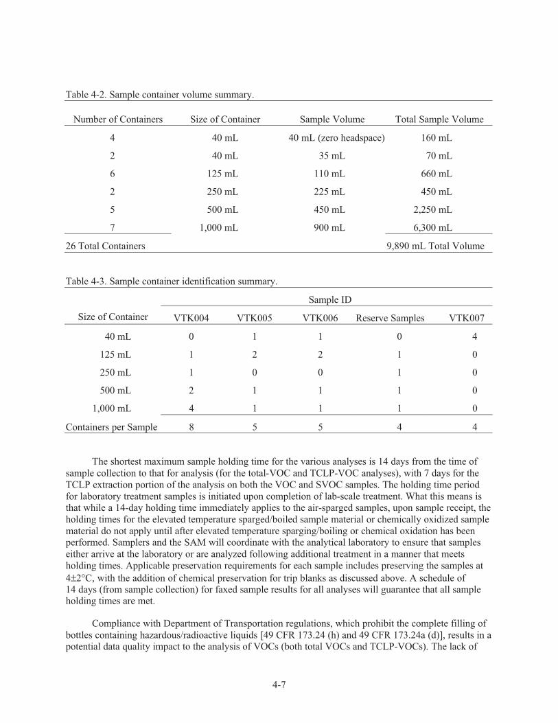
Table 4-2 summarizes the number of sample bottles required for this sampling activity, as well as the volume of each sample bottle, and the minimum filling requirement for each sample. As shown in
Table 4-2, a total of seven 1-L sample bottles, five 500-mL sample bottles, two 250-mL sample bottles,
six 125-mL sample bottles, and two 40-mL sample bottles are required for the Phase 1 sampling activity. The sample bottles are to be filled to approximately 90% of their capacity (except for the four 40-mL trip
blank samples, which will be filled to capacity [zero head-space] with water). Table 4-1 specifies the type
of analysis and condition represented by each sample bottle. Table 4-3 lists the sample identification numbers.
All samples will be collected from a single sample port located in the recirculation lines between
the cross-mixed tanks. Sampling should not be performed until after 42-hr of air-sparging has been
performed on each tank or the system engineer has determined that air-sparging is complete based on periodic off-gas monitoring results. In addition, sampling should not be performed until the tanks have
been adequately mixed (see Section 3.4). Prior to starting sampling operations, air-sparging must be
discontinued. This is necessary to keep the air-sparging activity from continuing to remove volatile
4-3
organics from the waste during sampling, which could bias the random variability of the samples. The
sample sets are to be collected in the order shown in Table 4-1, and the sampling line will be flushed before each sample set interval (the first, second and third sample sets, and the reserve sample set).
b
Detailed instructions to the laboratory on how to process the samples are provided in the project-specific
task order statement (TOS) provided by the SAM point of contact.
The sample bottles will be positioned in a containment structure and placed in secondary containment while filling. Wipes or other absorbent in the bottom of the secondary containment will be
used to absorb any drips/spills. Sudden discharges from the sample port will be minimized by using a fill
reservoir on the sample port downstream of the recirculation pump (although the peristaltic return pump that is to be attached to a designated sample drain valve upstream of the recirculation pump can be used
as a backup). The specifics as to how samples will be collected and material controlled will be covered in
facility work control, which is being prepared concurrently with this sampling plan. The waste will be drained directly from the valve to the bottles with no other associated apparatus. A funnel may be used to
facilitate transfer, if necessary.
Per SW-846 (EPA 1986), this waste is classified as a “concentrated” waste. This designation as a
concentrated waste eliminates the need to preserve VOA or metals samples to a pH less than 2.
b. The four trip blank samples listed last in Table 4-1 can be taken at any time during sampling.

4-4
Table 4-1. Consolidated tank waste sample breakdown.
Sample ID
Sample
Containers
in Set Sample Typea,b Analysesa,b
Minimum Required
Sample Volume
Minimum Total
Sample Volume
Volume of
Sample in
Container
(80-90%)
Container
Volume
VTK004-1st
Sample Set
Total VOA-A-1
(as-received)
VOA-A-1
VOA-A-MS
VOA-A-MSD
5 mL
5 mL
5 mL
15 mL
Total VOA-B-1
(after boiling)
VOA-B-1
VOA-B-MS
VOA-B-MSD
5 mL
5 mL
5 mL
15 mL
Total VOA-C-1
(after chem. ox.)
VOA-C-1
VOA-C-MS
VOA-C-MSD
5 mL
5 mL
5 mL
15 mL
1
Total Container 1 45 mL 100 mL 125 mL
TCLP VOA-A-1
(as-received)
TCLP-VOA-A-1
TCLP-VOA-A-MS
TCLP-VOA-A-MSD
25 mL
2 5 mL
25 mL
75 mL
TCLP VOA-B-1
(after boiling)
TCLP-VOA-B-1
TCLP-VOA-B-MS
TCLP-VOA-B-MSD
25 mL
25 mL
25 mL
75 mL
TCLP VOA-C-1
(after chem. ox.)
TCLP-VOA-C-1
TCLP-VOA-C-MS
TCLP-VOA-C-MSD
25 mL
25 mL
25 mL
75 mL
2
Total Container 2 225 mL 225 mL 250 mL
TCLP-MTL-A-1
(as received)
TCLP-MTL-A-1
TCLP-MTL-A-MS
TCLP-MTL-A-MSD
110 mL
110 mL
110 mL
330 mL
3
Total Container 3 330 mL 400 mL 500 mL
TCLP SVOA-A-1
(as-received)
TCLP-SVOA-A-1 430 mL 430 mL
TCLP SVOA-B-1
(after boiling)
TCLP-SVOA-B-1 430 mL 430 mL
4
Total Container 4 860 mL 900 mL 1,000 mL
TCLP SVOA-A
(as-received)
TCLP-SVOA-A-MS
TCLP-SVOA-A-MSD
430 mL
430 mL
860 mL
5
Total Container 5 860 mL 900 mL 1,000 mL
TCLP SVOA-B
(after boiling)
TCLP-SVOA-B-MS
TCLP-SVOA-B-MSD
430 mL
430 mL
860 mL
6
Total Container 6 860 mL 900 mL 1,000 mL
TCLP SVOA-C-1
(after chem. ox.)
TCLP-SVOA-C-1 430 mL 430 mL
7
Total Container 7 430 mL 450 mL 500 mL
TCLP SVOA-C
(after chem. ox.)
TCLP-SVOA-C-MS
TCLP-SVOA-C-MSD
430 mL
430 mL
860 mL
8
Total Container 8 860 mL 900 mL 1,000 mL
VTK005-2nd
Sample Set
Total VOA-A-2
(as-received)
VOA-A-2 5 mL 5 mL
Total VOA-B-2
(after boiling)
VOA-B-2 5 mL 5 mL
Total VOA-C-2
(after chem. ox.)
VOA-C-2 5 mL 5 mL
9
Total Container 9 15 mL 35 mL 40 mL
10 TCLP VOA-A-2
(as-received)
TCLP-VOA-A-2 25 mL 25 mL
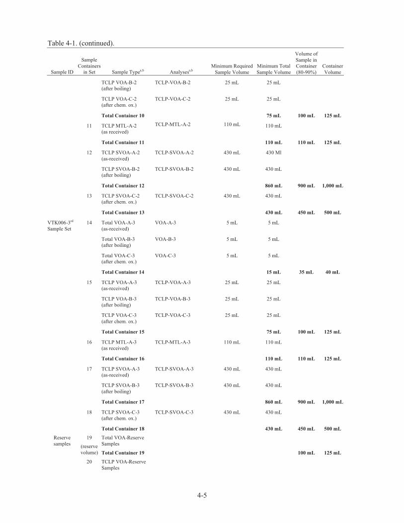
Table 4-1. (continued).
4-5
Sample ID
Sample
Containers
in Set Sample Typea,b Analysesa,b
Minimum Required
Sample Volume
Minimum Total
Sample Volume
Volume of
Sample in
Container
(80-90%)
Container
Volume
TCLP VOA-B-2
(after boiling)
TCLP-VOA-B-2 25 mL 25 mL
TCLP VOA-C-2
(after chem. ox.)
TCLP-VOA-C-2 25 mL 25 mL
Total Container 10 75 mL 100 mL 125 mL
TCLP MTL-A-2
(as received)
TCLP-MTL-A-2 110 mL 110 mL
11
Total Container 11 110 mL 110 mL 125 mL
TCLP SVOA-A-2
(as-received)
TCLP-SVOA-A-2 430 mL 430 Ml
TCLP SVOA-B-2
(after boiling)
TCLP-SVOA-B-2 430 mL 430 mL
12
Total Container 12 860 mL 900 mL 1,000 mL
TCLP SVOA-C-2
(after chem. ox.)
TCLP-SVOA-C-2 430 mL 430 mL
13
Total Container 13 430 mL 450 mL 500 mL
VTK006-3rd
Sample Set
Total VOA-A-3
(as-received)
VOA-A-3 5 mL 5 mL
Total VOA-B-3
(after boiling)
VOA-B-3 5 mL 5 mL
Total VOA-C-3
(after chem. ox.)
VOA-C-3 5 mL 5 mL
14
Total Container 14 15 mL 35 mL 40 mL
TCLP VOA-A-3
(as-received)
TCLP-VOA-A-3 25 mL 25 mL
TCLP VOA-B-3
(after boiling)
TCLP-VOA-B-3 25 mL 25 mL
TCLP VOA-C-3
(after chem. ox.)
TCLP-VOA-C-3 25 mL 25 mL
15
Total Container 15 75 mL 100 mL 125 mL
TCLP MTL-A-3
(as received)
TCLP-MTL-A-3 110 mL 110 mL
16
Total Container 16 110 mL 110 mL 125 mL
TCLP SVOA-A-3
(as-received)
TCLP-SVOA-A-3 430 mL 430 mL
TCLP SVOA-B-3
(after boiling)
TCLP-SVOA-B-3 430 mL 430 mL
17
Total Container 17 860 mL 900 mL 1,000 mL
TCLP SVOA-C-3
(after chem. ox.)
TCLP-SVOA-C-3 430 mL 430 mL
18
Total Container 18 430 mL 450 mL 500 mL
Reserve
samples
Total VOA-Reserve
Samples
19
(reserve
volume) Total Container 19 100 mL 125 mL
20 TCLP VOA-Reserve
Samples

Table 4-1. (continued).
4-6
Sample ID
Sample
Containers
in Set Sample Typea,b Analysesa,b
Minimum Required
Sample Volume
Minimum Total
Sample Volume
Volume of
Sample in
Container
(80-90%)
Container
Volume
(reserve
volume)
Total Container 20 225 mL 250 mL
TCLP-MTL-Reserve
Samples
21
(reserve
volume) Total Container 21 400 mL 500 mL
TCLP SVOA-A-
Reserve Samples
22
(reserve
volume) Total Container 22 900 mL 1,000 mL
VTK007 –
trip blank
23
Total VOA-T-1
VOA-T-1 40-mL bottle with
no headspace,
H2S04 to pH<2
40 mL 40 mL 40 mL
24 Total VOA-T-2 VOA-T-2 40-mL bottle with
no headspace;
H2S04 to pH<2
40 mL 40 mL 40 mL
25 TCLP VOA-T-1 TCLP-VOA-T-1 40-mL bottle with
no headspace;
H2S04 to pH<2
40 mL 40 mL 40 mL
26 TCLP VOA-T-2 TCLP-VOA-T-2 40-mL bottle with
no headspace;
H2S04 to pH<2
40 mL 40 mL 40 mL
a. Lettering nomenclature: A—as received by lab (after air-sparging); B—after boiling by lab; C—after chemical oxidation by lab.
b. Numbering nomenclature: 1—VTK004 - 1st sample set; 2—VTK005 - 2nd sample set; 3—VTK006 - 3rd sample set;
5—VTK007 - trip blank sets. No identifier for reserve set.
4-7
Table 4-2. Sample container volume summary.
Number of Containers Size of Container Sample Volume Total Sample Volume
4 40 mL 40 mL (zero headspace) 160 mL
2 40 mL 35 mL 70 mL
6 125 mL 110 mL 660 mL
2 250 mL 225 mL 450 mL
5 500 mL 450 mL 2,250 mL
7 1,000 mL 900 mL 6,300 mL
26 Total Containers 9,890 mL Total Volume
Table 4-3. Sample container identification summary.
Sample ID
Size of Container VTK004 VTK005 VTK006 Reserve Samples VTK007
40 mL 0 1 1 0 4
125 mL 1 2 2 1 0
250 mL 1 0 0 1 0
500 mL 2 1 1 1 0
1,000 mL 4 1 1 1 0
Containers per Sample 8 5 5 4 4
The shortest maximum sample holding time for the various analyses is 14 days from the time of
sample collection to that for analysis (for the total-VOC and TCLP-VOC analyses), with 7 days for the
TCLP extraction portion of the analysis on both the VOC and SVOC samples. The holding time period
for laboratory treatment samples is initiated upon completion of lab-scale treatment. What this means is that while a 14-day holding time immediately applies to the air-sparged samples, upon sample receipt, the
holding times for the elevated temperature sparged/boiled sample material or chemically oxidized sample
material do not apply until after elevated temperature sparging/boiling or chemical oxidation has been performed. Samplers and the SAM will coordinate with the analytical laboratory to ensure that samples
either arrive at the laboratory or are analyzed following additional treatment in a manner that meets
holding times. Applicable preservation requirements for each sample includes preserving the samples at
4±2°C, with the addition of chemical preservation for trip blanks as discussed above. A schedule of 14 days (from sample collection) for faxed sample results for all analyses will guarantee that all sample holding times are met.
Compliance with Department of Transportation regulations, which prohibit the complete filling of
bottles containing hazardous/radioactive liquids [49 CFR 173.24 (h) and 49 CFR 173.24a (d)], results in a potential data quality impact to the analysis of VOCs (both total VOCs and TCLP-VOCs). The lack of

4-8
zero headspace for the total VOA and TCLP-VOA samples directly deviates from typical sample
protocol. As a result of the sample protocol deviation, it is expected that the validator would give a qualification flag to sample results for VOAs unless specific arrangements are communicated to the
validator. Such a flag should not impact final acceptance of the results by the agencies (DOE-ID, IDEQ,
EPA Region 10) because the samples are taken from an open air system that is continuously recirculated
following sampling and has already undergone at least 42 hr of 40 cfm air-sparging on each tank volume prior to sampling. In addition, the consolidated waste tanks will continue to be sparged following
sampling. Calculations indicate that the amount of air coming in contact with the waste post-sampling is
at least 400 times that experienced by the sealed sample bottles as they await sampling. Therefore, the samples with non-zero headspace should still be a conservative approximation of the actual condition
within the V-tank waste.
As shown in Table 4-1, additional sample bottles will be collected and used if sample containers break. The additional sample volume will be representative of the maximum sample volume for a
particular analysis (125 mL for total VOAs, 250 mL for TCLP-VOAs, and 1,000 mL for TCLP-SVOAs),
with one additional sample taken for each analysis type. If for some reason more than one container is
broken or a sample is in some way unusable, additional sample material from later conditions (boiling or chemical oxidation) can be used. The consolidated waste should be resampled only if all existing sample
material sent to the analytical laboratory has been exhausted. Therefore, additional sampling should only
occur when both the sample material is lost and when added conditions for sample evaluation, beyond that of air-sparging, are required. The PM is responsible to ensure that a Document Action Request
(DAR) is written and approved for any presampling changes to this characterization plan.
Sampling logbook(s) will be maintained in accordance with MCP-9227, “Environmental Services Project Logkeeping Practices” (2004).
All the particulars related to the laboratory’s handling of wastes, including the conditions for
lab-scale elevated temperature sparging/boiling or lab-scale chemical oxidation, will be addressed in the
project-specific contracts that the SAM will prepare.
4.1.3 Sampling Equipment and Documentation
Sampling equipment, documentation, and any other supplies that will be used for sampling are
identified in MCP-9227 (2004) and MCP-9228 (2004). The following specific items or appropriate substitutes are required for this sampling activity:
• Bottles (including extras in the event of breakage)
• Funnel, if needed
• Secondary containment may be required—facility to direct
• Sample decontamination materials
• Lead shielding may be required—Radiological Control to direct
• Peristaltic sample return pump with a quick disconnect line for connection to the return interface
drain valve (to be used for sample residue returns and a backup for the existing sampling port)
• Backup line for the peristaltic pump system

4-9
• Personal protective equipment (PPE) designated in the work control to be provided by the facility
and any applicable RWP
• Chain of Custody forms
• Field guidance forms/labels/waterproof pens
• Logbook
• Wipes/absorbent towels
• Laboratory Task Order Statement
• Final plan
• Source term information provided by project
• Forms required under MCP-9228 for radiological shipment
• Packaging required by Packaging and Transportation (P&T)—expected to be drums—and all
required components of packaging
• Adhesive tape (clear, duct, and strapping), shipping labels, parafilm
• Liner bags, individual sample bags
• Custody seals.
4.1.4 Field Equipment Calibration and Set-Up
The industrial hygienist (IH) is responsible for the measurement and evaluation of any personnel
exposure chemical hazards. All IH instrumentation calibrations are performed per Guide (GDE)-196, “Industrial Hygiene Sampling Guide” (2003). If IH monitoring is required, it will be addressed in the
facility work control.
The radiological control technician (RCT) is responsible for measurement and evaluation of
personnel and material radiological contamination. RCT instrumentation calibrations are performed per procedures in Company Manual 15D.
4.1.5 Sample Designation and Labeling
Each sample bottle will contain a label identifying the unique field sample number. Uniqueness is required for maintaining consistency and preventing the same identification code from being assigned to
more than one sample. A systematic character code will be used to uniquely identify all samples. The
SAM will generate a sampling table, numbers, and labels that correlate directly to characterization sampling (refer to Appendix A). The information on the label and label placement are as provided in
MCP-9228.
4.1.6 Chain of Custody
All samples collected will be managed via chain of custody in accordance with MCP-9228.
4-10
4.1.7 Sampling Design and Procedures
Four sample sets (three samples per analysis, plus a fourth “reserve” sample set) will be taken in sequence from the valve following complete sparging and recirculation activities. The material is
primarily liquid, but also includes sludge, which will settle out after collection. The media is described as
a waste that represents the material from the V-1, V-2, V-3, and V-9 tank contents (and four other minor
volume waste streams). The required analyses and sample container volumes are listed in Table 4-1. Specific sample identifiers are listed in the Sampling and Analysis Plan table in Appendix A. Instructions
for collecting waste samples from the valve are provided in the following subsection.
4.1.7.1 V-Tank Waste Sampling
1. Review the sample plan and all facility work control documentation.
2. Ensure that all training is current.
3. Ensure that all required equipment is available and staged for use.
4. Ensure that all preliminary paperwork has been completed—source term, MCP-9228 forms
required for certification of shipping containers, and request for P&T assistance.
5. Ensure that the sampling is on the plan of the day, a RWP is in place, and RCT support is available.
6. Ensure that all support personnel critical to completing sample collection, packaging, and shipment are available.
7. Ensure that trip blanks have been prepared/provided.
8. Pre-mark all sample bottles (except the trip blanks) to 90% of full volume. The specific volumes and construction types of bottles designated in Table 4-1 must be used for all sample collection
activities.
9. Verify with the system engineer that both consolidation tank volumes have been adequately air-sparged, that cross-mixing of tank volumes is underway at a rate of at least 50 gal/min, that
cross-mixing has been performed for at least 8 hr (11 hr preferable), and that cross-mixing
operations will continue during sampling. Document in the logbook.
10. Hold a documented pre-job briefing in accordance with MCP-3003.
11. Discontinue air-sparging activities on the cross-mixing tanks.
12. Don required PPE as specified in the work control and RWP.
13. Attach the peristaltic return pump to the sample return interface valve located in the recirculation lines between the cross-mixed tanks.
14. Stage secondary containment and a container for flushing the sample system, and place absorbent
material in the bottom of the containment (unless this step has already been completed by Facility
Operations or other).
15. Open the sample valve(s).

4-11
16. Proceed to flush the sample system into the secondary container(s) under direction of the system
engineer.
17. Stage prelabeled bottles in vicinity of the sample system (unless this action has already been
completed during site preparation activities). The samples shall be collected in the order shown in
Table 4-1.
18. Slowly manipulate the sample system to avoid splashing and to control flow, allowing the waste to flow gently (with minimal entry disturbance) into the bottles. Fill to 90% of bottle capacity, then
close the valve. If necessary, use a funnel to facilitate transfer.
NOTE: The sample system will need to be closed between each sample. Bottles will be wiped thoroughly in the event of any residual sample external contamination. There is no need to check the pH. The
pH is known to be 6–8.
19. Tightly seal the sample container lid by hand. Note that parafilm is not required for VOCs, and
handling of bottles must be minimized as much as possible due to as low as reasonably achievable
(ALARA) concerns.
20. Flush the sample line between each sample set per steps 14 and 15.
21. Close sample valve(s) when sample operations are discontinued.
22. Package each sample bottle in compliance with MCP-9228 and P&T instruction. Remove the
collected samples from the glovebox, and place them in a sample refrigerator for at least 12 hours prior to packaging and shipment (to allow for sample settling).
23. Return the collected flush liquid (from Step 16) to the consolidated waste volume using the
peristaltic return pump system.
24. Turn off the peristaltic pump.
25. Resume air-sparging activities on the consolidation tanks (while continuing the cross-mixing). The
air-sparging shall be at a total rate of at least 40 cfm in the consolidation tanks.
26. Place the sample bottles into a Department of Transportation (DOT)-approved container(s) in compliance with MCP-9228 and P&T instruction (after allowing for at least 12 hrs of refrigerated
storage).
27. Radiation Control personnel will perform a contamination survey of the resulting package(s) and perform additional decontamination of the package(s) exterior surface(s), where necessary. Have
the sample package(s) released from a contamination control standpoint. Arrange for the
package(s) to be picked up by P&T and shipped to the desired analytical laboratory.
28. Clean up area, bag samples, and perform any other exit activities under Radiation Control direction. The WGS facility representative will have provided specific directions as to the
management and control of any sampling generated waste. It is possible that once the samples are
bagged, they will not be accessible for parafilming (VOAs excluded), which deviates from MCP-9228.

4-12
29. The logkeeper will note any physical characteristics (odor, color, any suspended materials) in the
field logbook. This will likely be performed when samplers are out of the contamination control area.
30. Arrangements will have been made to transport the material from the V-tank area to a Radiological
Engineering-approved storage pending coordination of packaging and off-Site shipment.
NOTE: A sample storage refrigerator will be used, if necessary, because locked storage of high activity samples is expected by Radiological Control personnel pending shipment off-Site.
31. Handle samples in accordance with the MCP-9228 unless otherwise noted in work control.
4.1.8 Sample Transport
Due to the anticipated consistency of the material and the fact that solids will be suspended in
solution, solids will settle after material is sampled. The settling of solids is especially important to consider with regard to packaging and shipment. The risk assessor has determined that, while in solution,
the dose rate anticipated on a 1-liter sample would be approximately 84 millirem/hour (mRem/hr);
however, once the sludge has settled out, the bottom phase may exhibit a dose rate as high as
155 mRem/hr per liter at the bottom (at contact). This information has been provided to SAM, project representatives, and the facility P&T representative. Actions are being taken to ensure that the special
packaging and components of that packaging will be readily available when sampling occurs. It is
expected that the final radiological readings will be taken just prior to packaging the samples and that packaging will occur at least 12 hours following sample collection (to allow for sufficient settling of the
waste prior to packaging and shipment). The specific sample location and analyses to be performed are
identified in Table 4-1.
Preliminary calculations showed that the samples can be shipped in strong tight packaging under an
exclusive use shipment. As much as possible, shipping documentation will be prepared, and packaging
and packaging materials will be identified prior to sampling. However, final packaging and shipping will
be in accordance with P&T procedures and DOT regulations. P&T will be notified at least one week in advance of the actual sampling in order to prepare the appropriate documentation and schedule the
transport vehicle.
4.1.9 Waste Management
Wastes generated during the characterization project will include sampling equipment—wipes,
funnel, secondary containment, and PPE. WGS personnel will coordinate waste disposal activities in
accordance with INEEL procedures. Waste will be bagged, labeled, and stored in an approved storage
area pending disposition. The project manager, with assistance from WGS, will prepare waste determination and disposition forms for determining the disposition routes for all waste generated during
sampling and analysis.
The project has requested that the following information be communicated to the performing laboratory:
• All sample material, altered and unaltered, are to be returned to the INEEL as defined in the TOS
• The altered and unaltered samples can be mixed with each other

4-13
• The sample waste (altered and unaltered) can be returned to the bulk consolidated waste tank
without adding any more waste codes
• All waste must be characterized, and WGS personnel must preapprove returning the sample
material to the V-tank consolidated waste.
4.2 Sample Analysis
The INEEL SAM will approve the laboratory performing sample analysis. This laboratory will
analyze the samples in accordance with project requirements and ER-SOW-394, “Idaho National
Engineering and Environmental Laboratory Sample and Analysis Management Statement of Work for
Analytical Services” (2004).
Project-specific request for analyses forms or TOS(s) identify additional requirements for
laboratory analysis. The following sections identify analysis requirements for the characterization project.
4.2.1 Analytical Methods
To ensure that data of acceptable quality are obtained from the characterization project, standard
EPA laboratory methods will be used to obtain sample data (see Section 3.2). Analytical methods to be
used for this characterization project are identified in the laboratory contract. All special conditions and
handling to meet project DQOs must be specified in the project-specific laboratory contract.
The non-characteristic confirmation must be performed to complete RCRA/TSCA hazardous waste
determination and to demonstrate that the V-tank waste meets or does not meet the ICDF Waste
Acceptance Criteria (WAC). The project will follow standard analytical procedures (SW-846 Method 8260B for volatiles, 8270C for semivolatiles, 6010B for metals, and 7470A for mercury).
If necessary, evaluations will be performed utilizing SIM (Section 7.5.12 for 8260B, Section 7.5.5
for 8270C) for the targeted organic contaminants identified in Tables 3-1 and 3-2 immediately following standard analytical methods. This will be performed using the same prepared samples used for standard
analytical methods. If higher resolution equipment is required for any of these organics, the extraction
procedures will also use the same prepared samples, but with analyses conducted via either the
high-resolution gas chromatograph (GC)/low-resolution mass spectrometry (MS) equipment described in Method 8280 or the high-resolution GC/high-resolution MS equipment described in Method 8290.
The removal of sample material from each sample container must be performed in a manner that
provides a representative portion of sludge and supernatant material in each sample. The analytical laboratory makes the final determination on how to accomplish this. All analytical laboratory activities
associated with sample removal needs to be performed in accordance with sample preparation measures
documented in SW-846.
Any deviations from this information will be fully documented, and the laboratory will inform the
project manager of the deviations.
Applying conditions of elevated temperature sparging/boiling or chemical oxidation shall not be
performed until written approval to proceed has been obtained from the project engineer. The project engineer will be responsible for reviewing the results of the most recent analyses before deciding if
further treatment is required for either the non-characteristic confirmation or the Phase 1 treatment
evaluation objectives.

4-14
4.2.2 Instrument Calibration Procedures
Laboratory instrumentation will be calibrated in accordance with the specific laboratory quality assurance plan. The SAM analytical laboratory authorization processes provide assurance that the
analytical laboratories authorized to perform analysis maintain an appropriate laboratory quality
assurance plan that addresses instrument calibration.
4.2.3 Laboratory Records
Laboratory records are required to be maintained in accordance with the specific laboratory quality
assurance plan. The SAM analytical laboratory authorization processes provide assurance that the
analytical laboratories authorized to perform analysis maintain an appropriate laboratory quality assurance plan that addresses laboratory records.
4.3 Data Management and Document Control
4.3.1 Data Reporting
The project has requested preliminary information via a 14-day facsimile from the laboratory with
a 21-calendar-day standard deliverable to follow for the complete summary data package for this work. The final data package documentation will conform to the criteria specified in ER-SOW-394. The ER
Statement of Work (SOW) prepared by the INEEL SAM is the standard means by which analytical data
deliverable requirements are defined by INEEL projects to laboratories used by the INEEL. All laboratories used by this project will adhere to the documents used to establish technical and reporting
standards.
4.3.2 Data Validation
Analytical data validation is the comparison of analytical results versus the requirements
established by the analytical method. The purpose of the data validation effort is to determine whether the
resulting analytical data are technically and legally defensible and reliable. The validation effort involves
the evaluation of all sample-specific information generated from sample collection to receipt of the final data package. As such, the validation process is generally not initiated (and cannot be completed) until
after all data packet deficiencies (if encountered) have been resolved. This is commonly done via a
request for data resubmittals from the analytical laboratory. The final product of the validation process is the validation report. The validation report communicates the quality and usability of the data to the
decision-makers. Included in the final report is information related to the qualification of all data,
including the identification of any flagged data and the reason and impact of the flagging.
The data for this project require rush validation. Level B validation is requested for all sample data
reports generated during this project. The validation report will contain an itemized discussion of the
validation process and results. Copies of the data forms annotated for qualification will be attached to the
report.
4.3.3 Data Quality Assessment
The project data quality assessment and validation process is used to determine whether the data
meet the project DQOs. Additional steps of the data quality assessment process may involve data plotting, testing for outlying data points, and other statistical analyses relative to the characterization project
DQOs.

4-15
Assessment of the data to determine data precision, accuracy, representativeness, reproducibility,
and completeness will be performed in accordance with QAPjP DOE-ID-10587 (2004).
4.3.4 Final Characterization Report
A final characterization report will be prepared for this project per applicable program
requirements; Donna Kirchner (6-9873) is the ESP point of contact for review of data and issuance of the
closure report summarizing the sampling activity and the findings. The WGS facility representative will work with the ESP point of contact in requesting specific information be included in the summary tables
so that the data can be used to facilitate preparation of the Integrated Waste Track System profile. The
final report will contain a summary of all of the sample data generated during this sampling effort, the log notes, the pertinent notes to the file, the Chain of Custody forms, and the final sampling plan. The final
report will also describe the sample collection effort, including any items that might impact the quality of
the data. A description of the data quality assessment process may also be included. The final report will discuss how the data will be used. The DQOs will be reviewed and evaluated to determine if the
characterization project objectives were met.
4.3.5 Document Control
Refer to MCP-9227, “Environmental Services Project Logkeeping Practices” (2004) and MCP-9228, “Environmental Sample Management” (2004). Document control consists of the clear
identification of all project-specific documents in an orderly form, secure storage of all project
information, and controlled distribution of all project information. Document control ensures controlled documents of all types related to the project will receive appropriate levels of review, comment, and
revision as necessary. The project manager is responsible for properly maintaining project documents
according to INEEL document control requirements. Upon completion of the characterization project, all project documentation and information will be transferred to compliant storage according to project,
program, and company requirements. This information may include field logbooks, Chain of Custody
forms, laboratory data reports, engineering calculations and drawings, and final technical reports.
5-1
5. HEALTH AND SAFETY REQUIREMENTS
As previously discussed, this sampling activity will be covered under Standard (STD)-101 (2004)
work control and the Health and Safety Plan for V-Tank Site Remediation at Test Area North, Waste Acceptance Group 1, Operable Unit 1-10 (ICP 2004) provided by project personnel. Work will also be
governed under a task-specific Radiological Work Permit (RWP). An ESP representative will review the
work control documents to ensure that all sampling hazards are addressed and mitigated. All job hazards
along with corresponding mitigation requirements are documented on a Job Safety Analysis form per MCP-3450, “Developing and Using Job Safety Analyses” (2000). The project is responsible for ensuring
that the cognizant health and safety professionals review and approve the health and safety
documentation.
The persons identified in Section 2 and by the project are identified as reviewers, and their
concurrence with this plan is documented by their approval signatures on Document Action Request
(DAR) # 300958.
6-1
6. REFERENCES
49 CFR 173.24, 2003, “Shippers General Requirements for Shipments and Packagings,” Code of Federal
Regulations, Office of Federal Register.
DOE, EPA, IDEQ, 2004, Record of Decision (ROD) Amendment for V-Tanks TSF-09 and TSF-18 and
Explanation of Significant Differences (ESD) for the PM-2A Tanks TSF-26 and TSF-06, Area 10,
at Test Area North (TAN) Operable Unit (OU) 1-10, DOE/ID-10682.
DOE/NE-ID, 2004, Group 2 Remedial Design/Remedial Action Work Plan Addendum 2 for the TSF-09/18 V-Tanks and Contents Removal and Site Remediation Test Area North, Waste Area
Group 1, Operable Unit 1-10, DOE/NE-ID-11150, Rev. 1, November 2004
DOE-ID, 2003, Technology Evaluation Report for the V-Tanks, TSF-09 and TSF-18, at Waste Area Group 1 (WAG-1) Operable Unit (OU) 1-10, DOE/ID-11038, Rev. 0, April 2003.
DOE-ID, 2004a, Quality Assurance Project Plan for Waste Groups 1,2,3,4,5,6,7,10 and Inactive Sites,
DOE-ID-10587, Rev. 8.
DOE ID, 2004b, INEEL Waste Acceptance Criteria (WAC), DOE/ID-10381, June 2004.
EDF-3077, 2004, “Risk-Based Approach for Management of PCB Remediation Waste from V-Tanks,”
Rev. 1, November 2004.
EDF-4885, 2004, “Reevaluation of Characteristic Toxicity Designation For V-Tank Waste, Using Existing Sample Data,” Rev. 1.
EDF-4928, 2004, “Potential Feed Streams for Inclusion into V-tank Treatment Process.”
EPA, 1986, Test Methods for Evaluation of Solid Waste.
EPA, 2000, Guidance for the Data Quality Objective Process (EPA QA/G-4), EPA/600/R-96/055, U.S.
Environmental Protection Agency, Office of Research and Development, Washington, D.C. 20460.
ER-SOW-394, 2004, “Idaho National Engineering and Environmental Laboratory Sample and Analysis
Management Statement of Work for Analytical Services,” Rev. 2, May 2004.
GDE-196, 2003, “Industrial Hygiene Sampling Guide,” Rev. 0.
ICP, 2004, Health and Safety Plan for the V-Tanks Site Remediation at Test Area North, Waste
Acceptance Group 1, Operable Unit 1-10, ICP/EXT-04-00429, Rev. 1, November 2004.
ICP-MCP-9439, 2004, “Environmental Sampling Activities at the INEEL,” Rev. 0.
MCP-3003, 2003, “Performing Pre-Job Briefings and Documenting Feedback,” Rev. 11.
MCP-3450, 2000, “Developing and Using Job Safety Analyses,” Rev. 2.
MCP-3472, 1999, “Identification and Characterization of Environmentally Regulated Waste,” Rev. 0.
MCP-9227, 2004, “Environmental Services Project Logkeeping Practices,” Rev. 6.
6-2
MCP-9228, 2004, “Environmental Sample Management,” Rev. 5.
Services Authorization Form 3389.
STD-101, 2004, “Integrated Work Control Process,” Rev. 16.
TEM-104, 2004, “Model for Preparation of Characterization Plans,” Rev. 1.
A-1
Appendix A
Sampling and Analysis Plan Table

A-2

A-3

B-1
Appendix B
Sparging Calculations

B-2

B-3
Appendix B Sparging Calculations
The calculation assumes that no more than 7,200 gallons of sludge are in each tank at any one time, one
tank is not sparged and contains 450 parts per million (ppm) TCE, while the other tank is sparged
sufficiently to contain no TCE, and that the pumping rate between tanks is at 50 gallons/minute. All of these conditions are “worst-case”
Table B-1. Sparging time to ensure consolidated wastes are well mixed before sampling.
Time (hr)
Tank 1a Conc. TCE
(mg/kg) Tank 2
a Conc. TCE
(mg/kg) % Tank 1 Conc. over Tank 2 Conc.
0 450.0 0.0
0.25 405.7 44.3 816
0.5 371.7 78.3 375
0.75 344.1 105.9 225
1 321.7 128.3 151
1.25 303.5 146.5 107
1.5 288.8 161.2 79
1.75 276.8 173.2 60
2 267.0 183.0 46
2.5 252.7 197.3 28
3 243.3 206.7 18
3.5 237.0 213.0 11
4 232.9 217.1 7.3
5 228.4 221.6 3.1
6 226.5 223.5 1.3
7 225.7 224.3 0.58
8 225.3 224.7 0.25
9 225.1 224.9 0.11
10 225.1 224.9 0.048
11 225.0 225.0 0.021
12 225.0 225.0 0.0090
13 225.0 225.0 0.0039
14 225.0 225.0 0.0017
15 225.0 225.0 0.00074
16 225.0 225.0 0.00032
17 225.0 225.0 0.00014
18 225.0 225.0 0.00006
a. 7,200 gal capacity, 50 gal/min flow rate.