icd 01 -interface control document for raw water · icd 01 -interface control document for raw...
TRANSCRIPT
• Document title:
ICD 01 - Interface Control Document for Raw Water
II 11111111111111111111111111 R11628951
Document number: 24590-WTP-ICD-MG-01-001, Rev 4
Contract:
Department:
NOTE:
Approved by:
Issue Status:
Date Issued:
River Protection Project Waste Treatment Plant 2435 Stevens Center Place Richland, WA 99354 United States of America Tel: 509 371 2000
DE-AC27-01RV14136 Contract deliverable: C.9.1
Project Management
All WTP Interface Partner concurrence signatures found on the
following page shall be obtained prior to approval of this ICD.
Marshall Miller
Print Name
I ,t'it.w (/.,</ ;,- ---~-· ~-
signature
ICD 01 Team Lead and Principal Author
Ap2roved
01/2 r/:zoti
NOTE: This document defines current service needs, future needs, and service gaps. The identified service levels do not represent contractual obligations between service recipient and providers. Future contractual and funding actions to close service gaps will be accomplished by integration between the federal offices as part of the budget planning process.
24590-PADC-F00041 Rev 6 (1/22/2009)
24590-WTP-ICD-MG-01-001, Rev 4 ICD 01 - Interface Control Document for Raw Water
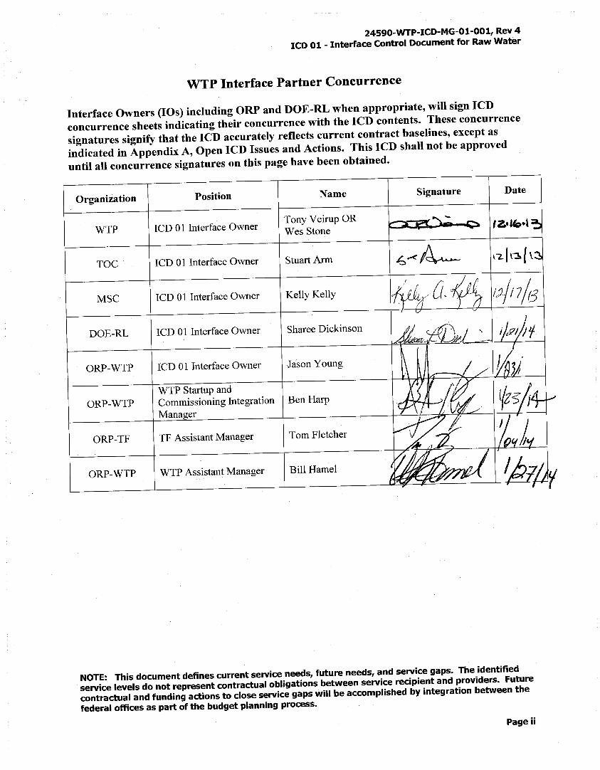
WTP Interface Partner Concurrence
Interface Owners (IOs) including ORP and DOE-RL when appropriate, will sign ICD concurrence sheets indicating their concurrence with the ICD contents. These concurrence signatures signify that the ICD accurately reflects current contract baselines, except as indicated in Appendix A, Open ICD Issues and Actions. This ICD shall not be approved until all concurrence signatures on this page have been obtained.
Organization Position Name I Signature I Date
WTP ICD 01 Interface Owner Tony Veirup OR
r==~Q l'z..'" .. 1 Wes Stone
TOC I ICD 01 Interface Owner I StuartArm \"'2.f r~{ \~1 -
MSC I ICD 01 Interface Owner I Kelly Kelly i,h PV1 ( j c '~ 11,)-/l 7 /3 I , l/ ~
I I
DOE-RL ICD 01 Interface Owner Sharee Dickinson
ORP-WTP ICD 01 Interface Owner Jason Young
WTP Startup and ORP-WTP I Commissioning Integration \ Ben Harp
Manager
ORP-TF I TF Assistant Manager Tom Fletcher
ORP-WTP I WTP Assistant Manager Bill Hamel
NOTE: This document defines current service needs, future needs, and service gaps. The identified service levels do not represent contractual obligations between service recipient and providers. Future contractual and funding actions to close service gaps will be accomplished by integration between the federal offices as part of the budget planning process.
Page ii
24590-WTP-ICD-MG-01-001, Rev 4 ICD 01 - Interface Control Document for Raw Water
Contents
1 Interface Description ............................................................................................................. !
1.1 Interface Definition ................................................................................................................................ 1
1.2 Functional Requirements ...................................................................................................................... 1
1.3 Physical Interfaces ................................................................................... ; ............................................. 1
1.4 Administrative Interfaces ...................................................................................................................... 3 1.4 .1 Operating Requirements ............................................................................................................ 5 1.4.2 Raw Water Delivery Schedule ................................................................................................... 6 1.4.3 Raw Water Physical Properties .................................................................................................. 7
1.5 Acceptance Criteria ............................................................................................................................... 7 1.5 .1 Integrated Hydrostatic Test Procedure ...................................................................................... 7 1.5.2 Backflow Prevention ................................................................................................................. 7 1.5.3 Raw Water Design Codes .......................................................................................................... 7
1.6 Configuration Management Items ........................................................................................................ 8
2 References .............................................................................................................................. 9
Appendix A - Open ICD 01 Issues and Actions ..............................................................•......... 12
Appendix B - ICD 01 Issues and Actions Closed Since Last Revision .................................... 13
Appendix C - ICD 01 Open Items List ....................................................................................... 14
Tables
Table 1
Table 2
Figures
Figure 1
Responsibilities for Raw Water ....................................................................................... 2
Interface Configuration Management Items .................................................................. 8
Raw Water Logic Diagram ................................................................................ : ............ 11
Page vii
24590-WTP-ICD-MG-01-001, Rev 4 ICD 01 - Interface Control Document for Raw Water
History Sheet Rev
A
0
2
3
4
Date
16 Jul 2001
14Mar 2002
15 Nov 2002
15 Nov 2003
26 Jun 2012
29 Jan 2014
Reason for revision Revised by
Issued for ORP concurrence 0 Stuenkel
Provided for ORP Contracting Officer to issue as Operative K Cleveland ICD. Upon issuance this document will supercede BNFL-5193-ID-01, Rev 6
Provided for ORP Contracting Officer to issue as Operative R Ciolli ICD as part of the required ICD update. Included ICFs: 24590-WTP-ICF-M-01-001, Rev 2, 24590-WTP-ICF-M-02-002, Rev 0, and 24590-WTP-ICF-M-02-001, Rev 0.
Provided for ORP Contracting Officer to issue as Operative . R Ciolli ICD as part of the required ICD update. Incorporated ICF 24590-BOF-ICF-ENG-03-005.
Periodic update. There are no open Issues or Actions associated with this ICD at this time. Incorporated responsibility for testing and maintaining Backflow Preventer Valves.
Periodic update. There are no open ICFs associated with this ICD at this time. This revision created new ICD Issue IOl-15, 24590-WTP-ATS-MGT-13-0557, Produce RWW Integrated Hydrostatic Test Procedure.
M Miller
M Miller
Page iii
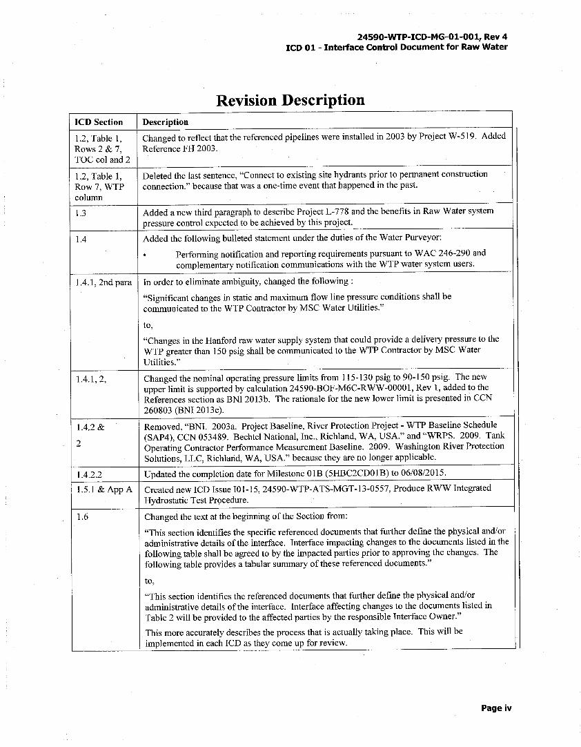
ICD Section
1.2, Table 1, Rows 2 & 7, TOC col and2
1.2, Table 1, Row7, WTP column
1.3
1.4
1.4.1, 2nd para
1.4.1,2,
1.4.2 &
2
1.4.2.2
1.5.l & App A
1.6
24590-WTP-ICD-MG-01-001, Rev 4 ICD 01 - Interface Control Document for Raw Water
Revision Description Description
Changed to reflect that the referenced pipelines were installed in 2003 by Project W-519. Added Reference FH 2003.
Deleted the last sentence, "Connect to existing site hydrants prior to permanent construction connection." because that was a one-time event that happened in the past.
Added a new third paragraph to describe Project L-778 and the benefits in Raw Water system pressure control expected to be achieved by this project.
Added the following bulleted statement under the duties of the Water Purveyor:
. Performing notification and reporting requirements pursuant to WAC 246-290 and complementary notification communications with the WTP water system users.
In order to eliminate ambiguity, changed the following:
"Significant changes in static and maximum flow line pressure conditions shall be communicated to the WTP Contractor by MSC Water Utilities."
to,
"Changes in the Hanford raw water supply system that could provide a delivery pressure to the WTP greater than 150 psig shall be communicated to the WTP Contractor by MSC Water Utilities."
Changed the nominal operating pressure limits from 115-130 psig to 90-150 psig. The new upper limit is supported by calculation 24590-BOF-M6C-RWW-00001, Rev 1, added to the References section as BNI 2013b. The rationale for the new lower limit is presented in CCN 260803 (BNI 2013c).
Removed, "BNI. 2003a. Project Baseline, River Protection Project - WTP Baseline Schedule (SAP4), CCN 053489. Bechtel National, Inc., Richland, WA, USA." and "WRPS. 2009. Tank Operating Contractor Performance Measurement Baseline. 2009. Washington River Protection Solutions, LLC, Richland, WA, USA." because they are no longer applicable.
Updated the completion date for Milestone OlB (5HBC2CD01B) to 06/08/2015.
Created new ICD Issue 101-15, 24590-WTP-ATS-MGT-13-0557, Produce RWW Integrated Hydrostatic Test Procedure.
Changed the text at the beginning of the Section from:
"This section identifies the specific referenced documents that further define the physical and/or administrative details of the interface. Interface impacting changes to the documents listed in the following table shall be agreed to by the impacted parties prior to approving the changes. The following table provides a tabular summary of these referenced documents."
to,
"This section identifies the referenced documents that further define the physical and/or administrative details of the interface. Interface affecting changes to the documents listed in Table 2 will be provided to the affected parties by the responsible Interface Owner."
This more accurately describes the process that is actualiy taking piace. This will be implemented in each ICD as they come up for review.
Page iv
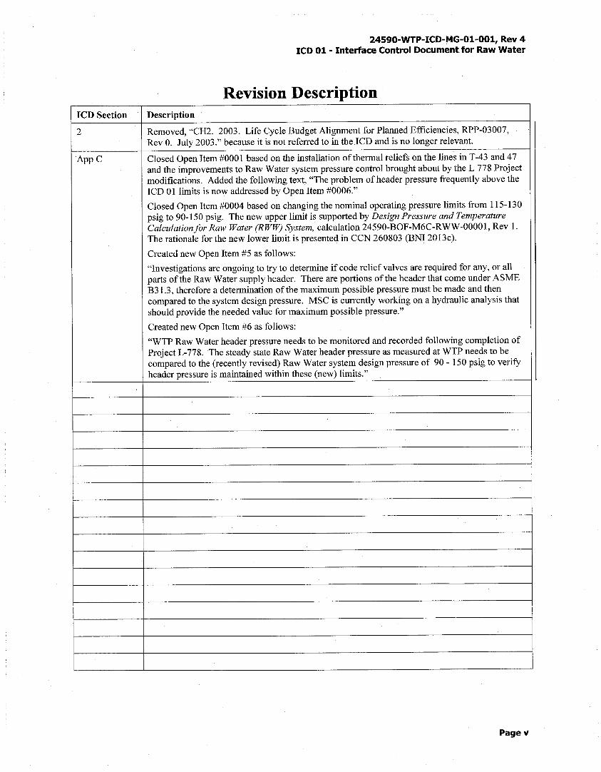
ICD Section
2
AppC
24590-WTP-ICD-MG-01-001, Rev 4 ICD 01- Interface Control Document for Raw Water
Revision Description Description
Removed, "CH2. 2003. Life Cycle Budget Alignment for Planned Efficiencies, RPP-03007, Rev 0. July 2003." because it is not referred to in the ICD and is no longer relevant.
Closed Open Item #0001 based on the installation of thermal reliefs on the lines in T-43 and 47 and the improvements to Raw Water system pressure control brought about by the L 778 Project modifications. Added the following text, "The problem of header pressure frequently above the ICD 01 limits is now addressed by Open Item #0006."
Closed Open Item #0004 based on changing the nominal operating pressure limits from 115-130 psig to 90-150 psig. The new upper limit is supported by Design Pressure and Temperature Calculation for Raw Water (RWW) System, calculation 24590-BOF-M6C-RWW-00001, Rev 1. The rationale for the new lower limit is presented in CCN 260803 (BNI 2013c).
Created new Open Item #5 as follows:
"Investigations are ongoing to try to determine if code relief valves are required for any, or all parts of the Raw Water supply header. There are portions of the header that come under ASME B3 l .3, therefore a determination of the maximum possible pressure must be made and then compared to the system design pressure. MSC is currently working on a hydraulic analysis that should provide the needed value for maximum possible pressure."
Created new Open Item #6 as follows:
"WTP Raw Water header pressure needs to be monitored and recorded following completion of Project L-778. The steady state Raw Water header pressure as measured at WTP needs to be compared to the (recently revised) Raw Water system design pressure of 90 - 150 psig to verify header pressure is maintained within these (new) limits."
Pagev
24590-WTP-ICD-MG-01-001, Rev 4 ICD 01 - Interface Control Document for Raw Water
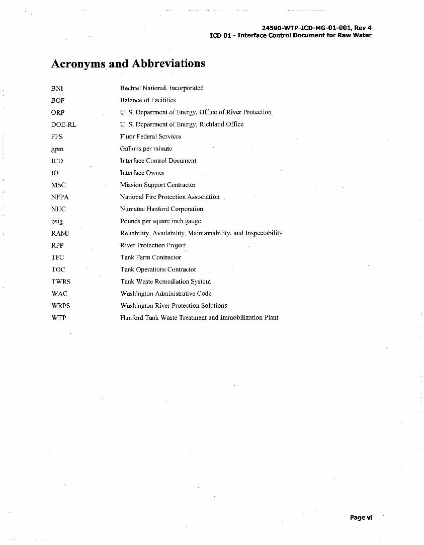
Acronyms and Abbreviations
BNI
BOF
ORP
DOE-RL
FFS
gpm
ICD
IO
MSC
NFPA
NHC
psig
RAMI
RPP
TFC
TOC
TWRS
WAC
WRPS
WTP
Bechtel National, Incorporated
Balance of Facilities
U.S. Department of Energy, Office of River Protection
U.S. Department of Energy, Richland Office
Fluor Federal Services
Gallons per minute
Interface Control Document
Interface Owner
Mission Support Contractor
National Fire Protection Association
Numatec Hanford Corporation
Pounds per square inch gauge
Reliability, Availability, Maintainability, and lnspectability
River Protection Project
Tank Farm Contractor
Tank Operations Contractor
Tank Waste Remediation System
Washington Administrative Code
Washington River Protection Solutions
Hanford Tank Waste Treatment and Immobilization Plant
Page vi
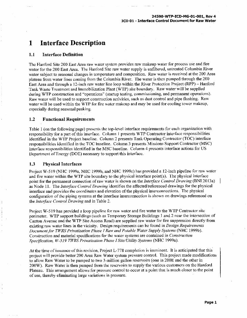
1 Interface Description
1.1 Interface Definition
24590-WTP-ICD-MG-01-001, Rev 4 ICD 01 - Interface Control Document for Raw Water
The Hanford Site 200 East Area raw water system provides raw makeup water for process use and fire water for the 200 East Area. The Hanford Site raw water supply is unfiltered, untreated Columbia River water subject to seasonal changes in temperature and composition. Raw water is received at the 200 Area plateau from water lines coming from the Columbia River. The water is then pumped through the 200 East Area and through a 12-inch raw water line loop within the River Protection Project (RPP)- Hanford Tank Waste Treatment and Immobilization Plant (WTP) site boundary. Raw water will be supplied during WTP construction and "operations" (startup testing, commissioning, and permanent operations). Raw water will be used to support construction activities, such as dust control and pipe flushing. Raw water will be used within the WTP for fire water makeup and may be used for cooling tower makeup, especially during seasonal peaking.
1.2 Functional Requirements
Table 1 (on the following page) presents the top-level interface requirements for each organization with responsibility for a part of this interface. Column 1 presents WTP Contractor interface responsibilities identified in the WTP Project baseline. Column 2 presents Tank Operating Contractor (TOC) interface responsibilities identified in the TOC baseline. Column 3 presents Missions Support Contractor (MSC) interface responsibilities identified in the MSC baseline. Column 4 presents interface actions for US Department of Energy (DOE) necessary to support this interface.
1.3 Physical Interfaces
Project W-519 (NHC 1999a, NHC 1999b, and NHC 1999c) has provided a 12-inch pipeline for raw water and fire water within the WTP site boundary to the physical interface point(s). The physical interface point for the permanent connection ofraw water is shown on the Interface Control Drawing (BNI 2013a) as Node 11. The Interface Control Drawing identifies the affected/referenced drawings for the physical interface and provides the coordinates and elevation of the physical interconnections. The physical configuration of the piping systems at the interface interconnection is shown on drawings referenced on the Interface Control Drawing and in Table 2.
Project W-519 has provided a loop pipeline for raw water and fire water to the WTP Contractor site perimeter. WTP support buildings (such as Temporary Storage Buildings 1 and 2 near the intersection of Canton A venue and the WTP Site Access Road) are supplied raw water for fire suppression directly from existing raw water lines in the vicinity. Design requirements can be found in Design Requirements Document for TWRS Privatization Phase I Raw and Potable Water Supply Systems (NHC 1999b). Construction and material specifications for the water systems are contained in Construction Specification, W-519 TWRS Privatization Phase I Site/Utility Systems (NHC 1999a).
At the time of issuance of this revision, Project L-778 completion is imminent. It is anticipated that this project will provide better 200 Area Raw Water system pressure control. This project made modifications to allow Raw Water to be pumped to two 3-million gallon reservoirs (one in 200E and the other in 200W). Raw Water is then pumped from the reservoirs to supply the various customers on the Hanford Plateau. This arrangement allows for pressure control to occur at a point that is much closer to the point of use, thereby eliminating large variations in pressure.
Page 1
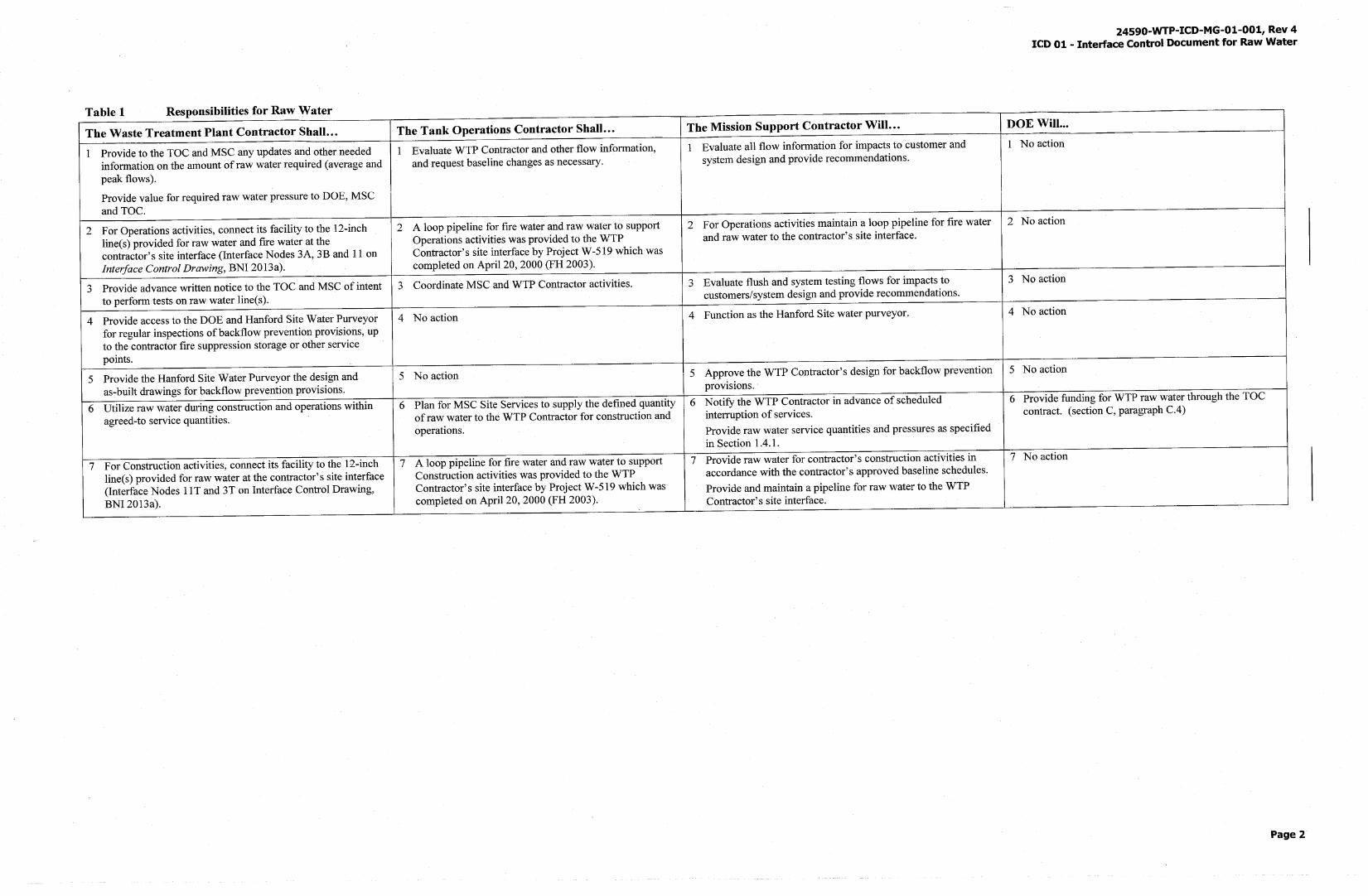
Table 1 Responsibilities for Raw Water
The Waste Treatment Plant Contractor Shall ... The Tank Operations Contractor Shall ...
1 Provide to the TOC and MSC any updates and other needed 1 Evaluate WTP Contractor and other flow information, information on the amount ofraw water required (average and and request baseline changes as necessary. peak flows).
Provide value for required raw water pressure to DOE, MSC and TOC.
2 For Operations activities, connect its facility to the 12-inch 2 A loop pipeline for fire water and raw water to support line(s) provided for raw water and fire water at the Operations activities was provided to the WTP contractor's site interface (Interface Nodes 3A, 3B and 11 on Contractor's site interface by Project W-519 which was Interface Control Drawing, BNI 2013a). completed on April 20, 2000 (FH 2003).
3 Provide advance written notice to the TOC and MSC of intent 3 Coordinate MSC and WTP Contractor activities. to perform tests on raw water line(s).
4 Provide access to the DOE and Hanford Site Water Purveyor 4 No action for regular inspections ofbackflow prevention provisions, up to the contractor fire suppression storage or other service points.
5 Provide the Hanford Site Water Purveyor the design and 5 No action as-built drawings for backflow prevention provisions.
6 Utilize raw water during construction and operations within 6 Plan for MSC Site Services to supply the defined quantity agreed-to service quantities. of raw water to the WTP Contractor for construction and
operations.
7 For Construction activities, connect its facility to the 12-inch 7 A loop pipeline for fire water and raw water to support line(s) provided for raw water at the contractor's site interface Construction activities was provided to the WTP (Interface Nodes 11 T and 3T on Interface Control Drawing, Contractor's site interface by Project W-519 which was BNI 2013a). completed on April 20, 2000 (FH 2003).
The Mission Support Contractor Will ...
1 Evaluate all flow information for impacts to customer and system design and provide recommendations.
2 For Operations activities maintain a loop pipeline for fire water and raw water to the contractor's site interface.
3 Evaluate flush and system testing flows for impacts to customers/system design and provide recommendations.
4 Function as the Hanford Site water purveyor.
5 Approve the WTP Contractor's design for backflow prevention provisions.
6 Notify the WTP Contractor in advance of scheduled interruption of services.
Provide raw water service quantities and pressures as specified in Section 1.4.1.
7 Provide raw water for contractor's construction activities in accordance with the contractor's approved baseline schedules.
Provide and maintain a pipeline for raw water to the WTP Contractor's site interface.
24590-WTP-ICD-MG-01-001, Rev 4 ICD 01 - Interface Control Document for Raw Water
DOE Will ...
1 No action
2 No action
3 No action
4 No action
5 No action
6 Provide funding for WTP raw water through the TOC contract. (section C, paragraph C.4)
7 No action
Page 2
24590-WTP-ICD-MG-01-001, Rev 4 ICD 01 - Interface Control Document for Raw Water
During the construction period, backflow prevention valves will be temporarily located where the raw water supply loop crosses the WTP site perimeter fence at the northwest comer of the site (Node 3T on the Interface Control Drawing), and where the raw water supply loop crosses the WTP site perimeter fence at the southeast comer of the site (Node 11 Ton the Interface Control Drawing). The interface points will be the 12-inch flange on the discharge side of the backflow preventers. The WTP Contractor will be responsible for operation of the raw water supply loop between the two interface point locations. MSC Water Utilities will be responsible for testing and maintaining the backflow preventers and for updating the Hanford Site drawings when the corridor is returned to its control. MSC Water Utilities has agreed that the WTP Contractor is responsible for testing and maintaining the backflow preventer valves within the WTP site perimeter fence. A Washington State Department of Health certified Backflow Assembly Tester must perform these activities and forward the completed Backflow Prevention Assembly Test Reports and work histories to the Hanford Site Water Purveyor Office within five days of the work and/or testing being completed. A WTP site inner service loop will be progressively installed that will supply both temporary construction activities and permanent piping to the operating plant. This inner service loop is currently supplied by connections to the external service loop at Nodes 3A and 11.
Fire water for fire protection on the WTP site is provided by the WTP Contractor fire water system, which has redundant fire water tanks and the raw water system for some WTP locations. The raw water line provided fire protection to the entire WTP site during construction before the WTP Contractor fire water system became operational and continues to provide fire protection to some WTP facilities.
1.4 Administrative Interfaces
Raw water supplied from the interface will feed a manual refill of the fire water tanks and will be used for cooling tower makeup. The raw water requirement during the peak cooling tower makeup period is 725 gpm
The fire water tanks require minimum makeup of 730 gpm to fill one 350,000 gallon tank in 8 hours (NFPA 22). MSC Water Utilities has agreed that administrative controls can be implemented to increase flow rates during startup and operations to meet the fire water storage tank fill. These administrative controls will be negotiated between the WTP Contractor and MSC Water Utilities prior to filling the fire water storage tanks during WTP operations. A process or procedure will be in place describing the administrative controls prior to filling the fire water storage tanks during plant operations.
The respective organizations' design requirements include integrated safety management principles and are communicated through the interface in the requirements documents (for example, safety analysis reports), which will be identified in Table 2, as available.
No new hazards or accident scenarios are expected to be introduced through this interface that are not adequately controlled by the interface contractors and through controls placed across this interface. The physical and administrative controls to mitigate these risks using a graded approach have been or will be adequately addressed through requirements on each contractor's authorization basis.
The ICD team has not identified any deactivation or reliability, availability, maintainability, and inspectability (RAMI) considerations that require management across the interface. Systematic RAMI assessments of this interface have not been conducted.
Prior to hot commissioning, the raw water backflow preventers in place at Nodes 3T and 11 T, as shown on the Interface Control Drawing, will serve as cross-connection control between the WTP and Hanford Site raw water systems. At the start of hot commissioning, cross-connection control will be converted to
Page3
24590-WTP-ICD-MG-01-001, Rev 4 ICD 01 - Interface Control Document for Raw Water
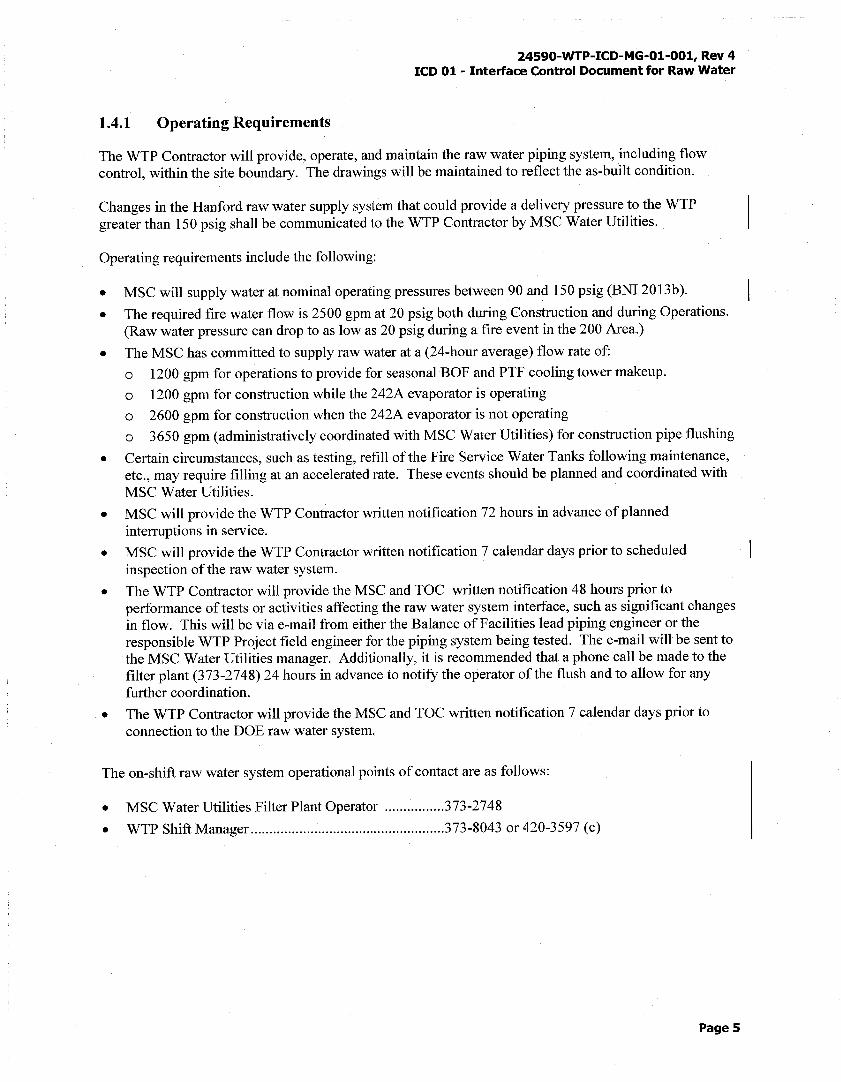
1.4.1 Operating Requirements
The WTP Contractor will provide, operate, and maintain the raw water piping system, including flow control, within the site boundary. The drawings will be maintained to reflect the as-built condition.
Changes in the Hanford raw water supply system that could provide a delivery pressure to the WTP greater than 150 psig shall be communicated to the WTP Contractor by MSC Water Utilities.
Operating requirements include the following:
• MSC will supply water at nominal operating pressures between 90 and 150 psig (BNI 2013b).
• The required fire water flow is 2500 gpm at 20 psig both during Construction and during Operations. (Raw water pressure can drop to as low as 20 psig during a fire event in the 200 Area.)
• The MSC has committed to supply raw water at a (24-hour average) flow rate of:
o 1200 gpm for operations to provide for seasonal BOF and PTF cooling tower makeup.
o 1200 gpm for construction while the 242A evaporator is operating
o 2600 gpm for construction when the 242A evaporator is not operating
o 3650 gpm (administratively coordinated with MSC Water Utilities) for construction pipe flushing
• Certain circumstances, such as testing, refill of the Fire Service Water Tanks following maintenance, etc., may require filling at an accelerated rate. These events should be planned and coordinated with MSC Water Utilities.
• MSC will provide the WTP Contractor written notification 72 hours in advance of planned interruptions in service.
• MSC will provide the WTP Contractor written notification 7 calendar days prior to scheduled inspection of the raw water system.
• The WTP Contractor will provide the MSC and TOC written notification 48 hours prior to performance of tests or activities affecting the raw water system interface, such as significant changes in flow. This will be via e-mail from either the Balance of Facilities lead piping engineer or the responsible WTP Project field engineer for the piping system being tested. The e-mail will be sent to the MSC Water Utilities manager. Additionally, it is recommended that a phone call be made to the filter plant (373-2748) 24 hours in advance to notify the operator of the flush and to allow for any further coordination.
• The WTP Contractor will provide the MSC and TOC written notification 7 calendar days prior to connection to the DOE raw water system.
The on-shift raw water system operational points of contact are as follows:
• MSC Water Utilities Filter Plant Operator ................ 373-2748
• WTP Shift Manager .................................................... 373-8043 or 420-3597 (c)
Pages
24590-WTP-ICD-MG-01-001, Rev 4 ICD 01 - lnteriace Control Document for Raw Water
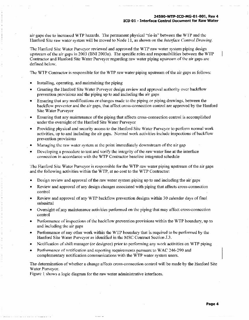
air gaps due to increased WTP hazards. The permanent physical "tie-in" between the WTP and the Hanford Site raw water system will be moved to Node 11, as shown on the Interface Control Drawing.
The Hanford Site Water Purveyor reviewed and approved the WTP raw water system piping design upstream of the air gaps in 2003 (BNI 2003a). The specific roles and responsibilities between the WTP Contractor and Hanford Site Water Purveyor regarding raw water piping upstream of the air gaps are defined below.
The WTP Contractor is responsible for the WTP raw water piping upstream of the air gaps as follows:
• Installing, operating, and maintaining the piping
• Granting the Hanford Site Water Purveyor design review and approval authority over backflow prevention provisions and the piping up to and including the air gaps
• Ensuring that any modifications or changes made to the piping or piping drawings, between the backflow preventer and the air gaps, that affect cross-connection control are approved by the Hanford Site Water Purveyor
• Ensuring that any maintenance of the piping that affects cross-connection control is accomplished under the oversight of the Hanford Site Water Purveyor
• Providing physical and security access to the Hanford Site Water Purveyor to perform normal work activities, up to and including the air gaps. Normal work activities include inspections ofbackflow prevention provisions
• Managing the raw water system at the point immediately downstream of the air gap
• Developing a procedure to test and verify the integrity of the raw water line at the interface connection in accordance with the WTP Contractor baseline integrated schedule
The Hanford Site Water Purveyor is responsible for the WTP raw water piping upstream of the air gaps and the following activities within the WTP, at no cost to the WTP Contractor:
• Design review and approval of the raw water system piping up to and including the air gaps
• Review and approval of any design changes associated with piping that affects cross-connection control
• Review and approval of any WTP backflow prevention designs within 3 0 calendar days of final submittal
• Oversight of any maintenance activities performed on the piping that may affect cross-connection control
• Performance of inspections of the backflow prevention provisions within the WTP boundary, up to and including the air gaps
• Performance of any other work within the WTP boundary that is required to be performed by the Hanford Site Water Purveyor as identified in the MSC Contract Section J.3.
• Notification of shift manager (or designee) prior to performing any work activities on WTP piping
• Performance of notification and reporting requirements pursuant to WAC 246-290 and complementary notification communications with the WTP water system users.
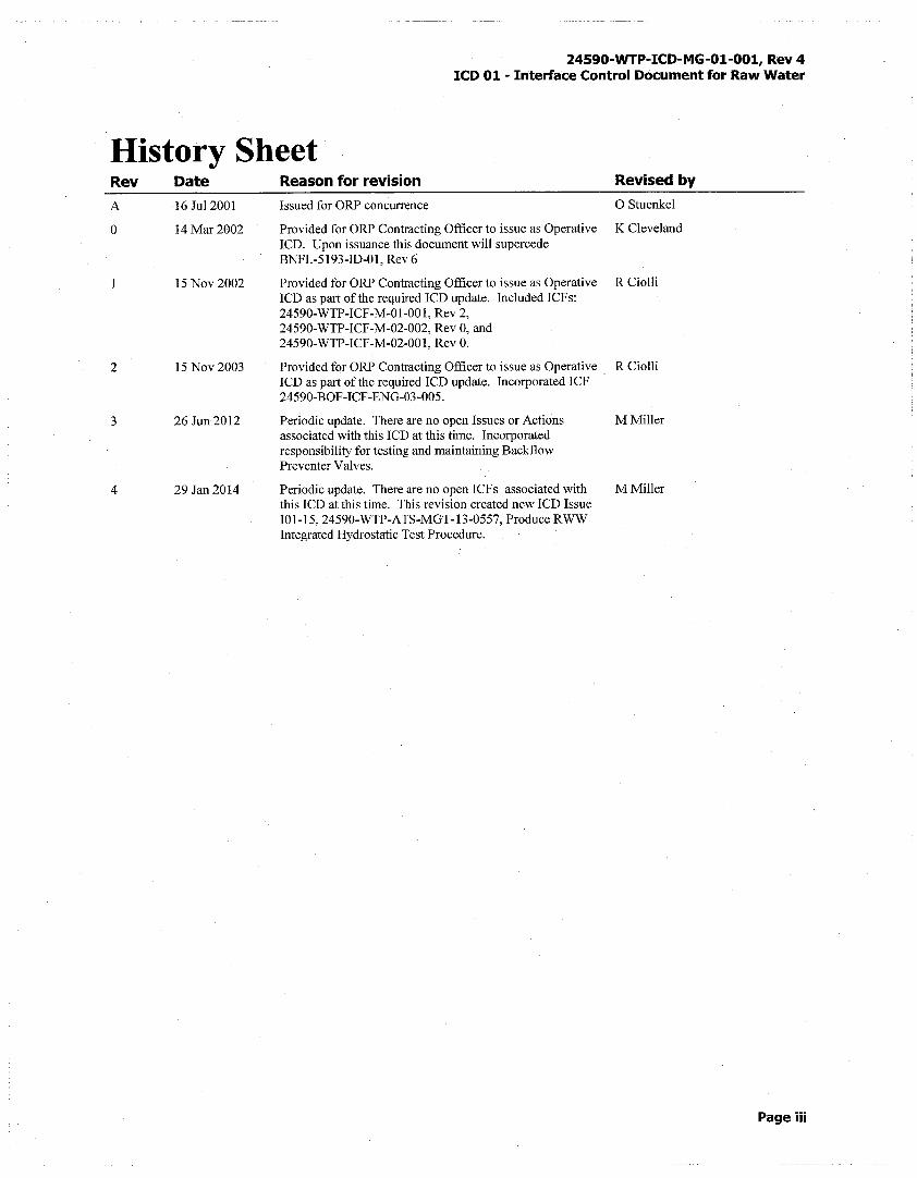
The determination of whether a change affects cross-connection control will be made by the Hanford Site Water Purveyor. Figure 1 shows a logic diagram for the raw water administrative interfaces.
Page4
24590-WTP-ICD-MG-01-001, Rev 4 ICD 01 - Interface Control Document for Raw Water
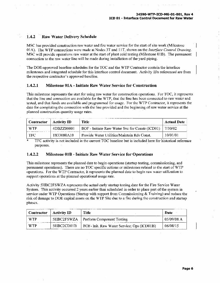
1.4.2 Raw Water Delivery Schedule
MSC has provided construction raw water and fire water service for the start of site work (Milestone OlA). The WTP connections were made at Nodes 3T and 11 T, shown on the Interface Control Drawing. MSC will provide operations raw water at the start of plant cold testing (Milestone OlB). The permanent connection to the raw water line will be made during installation of the yard piping.
The DOE-approved baseline schedules for the TOC and the WTP Contractor contain the interface milestones and integrated schedule for this interface control document. Activity IDs referenced are from the respective contractor's approved baseline.
1.4.2.1 Milestone OlA - Initiate Raw Water Service for Construction
This milestone represents the start for using raw water for construction operations. For TOC, it represents that the line and connection are available for the WTP, that the line has been connected to raw water and tested, and that funds are available and programmed for usage. For the WTP Contractor, it represents the date for completing the connection with the line provided and the beginning of raw water service at the planned construction quantity usage rates.
*
Contractor Activity ID Title Actual Date
WTP 4DBZZ00001 BOF - Initiate Raw Water Svc for Constr (ICDOl) 7/30/02
TFC T833080A10 Provide Water Utilities/Maintain Rds Const. 10/01/01
TFC activity is not included in the current TOC baseline but is included here for historical reference purposes.
1.4.2.2 Milestone OlB - Initiate Raw Water Service for Operations
This milestone represents the planned date to begin operations (startup testing, commissioning, and permanent operations). There are no TOC specific actions or milestones related to the start ofWTP operations. For the WTP Contractor, it represents the planned date to begin raw water utilization to support operations at the planned operational usage rate.
Activity 5HBC2FSWZA represents the actual early startup testing date for the Fire Service Water System. This activity occurred 2 years earlier than scheduled in order to place part of the system in service under WTP Operations (Startup with support from Commissioning & Training) and reduce the risk of damage to DOE capital assets on the WTP Site due to a fire during the construction and startup phases.
Contractor Activity ID Title Date
WTP 5HBC2FSWZA Perform Component Testing 05/09/08 A --·~----~--~-
WTP 5HBC2CD01B BOF- Init. Raw Water Service; Ops (ICDOlB) 06/08/15
Page 6
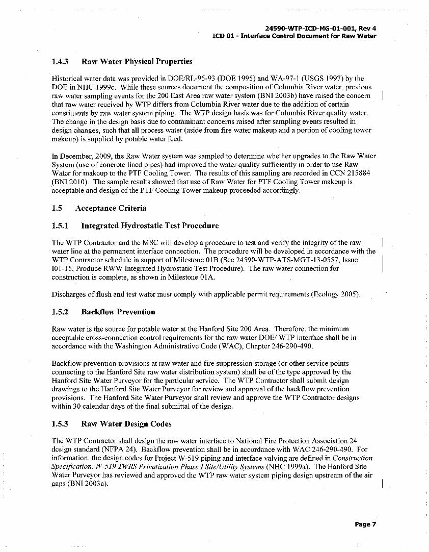
1.4.3 Raw Water Physical Properties
24590-WTP-ICD-MG-01-001, Rev 4 ICD 01 - Interface Control Document for Raw Water
Historical water data was provided in DOE/RL-95-93 (DOE 1995) and WA-97-1 (USGS 1997) by the DOE in NHC l 999c. While these sources document the composition of Columbia River water, previous raw water sampling events for the 200 East Area raw water system (BNI 2003b) have raised the concern that raw water received by WTP differs from Columbia River water due to the addition of certain constituents by raw water system piping. The WTP design basis was for Columbia River quality water. The change in the design basis due to contaminant concerns raised after sampling events resulted in design changes, such that all process water (aside from fire water makeup and a portion of cooling tower makeup) is supplied by potable water feed.
In December, 2009, the Raw Water system was sampled to determine whether upgrades to the Raw Water System (use of concrete lined pipes) had improved the water quality sufficiently in order to use Raw Water for makeup to the PTF Cooling Tower. The results of this sampling are recorded in CCN 215884 (BNI 2010). The sample results showed that use of Raw Water for PTF Cooling Tower makeup is acceptable and design of the PTF Cooling Tower makeup proceeded accordingly.
1.5 Acceptance Criteria
1.5.1 Integrated Hydrostatic Test Procedure
The WTP Contractor and the MSC will develop a procedure to test and verify the integrity of the raw water line at the permanent interface connection. The procedure will be developed in accordance with the WTP Contractor schedule in support of Milestone OlB (See 24590-WTP-ATS-MGT-13-0557, Issue 101-15, Produce RWW Integrated Hydrostatic Test Procedure). The raw water connection for construction is complete, as shown in Milestone OlA.
Discharges of flush and test water must comply with applicable permit requirements (Ecology 2005).
1.5.2 Backflow Prevention
Raw water is the source for potable water at the Hanford Site 200 Area. Therefore, the minimum acceptable cross-connection control requirements for the raw water DOE/ WTP interface shall be in accordance with the Washington Administrative Code (WAC), Chapter 246-290-490.
Backflow prevention provisions at raw water and fire suppression storage (or other service points connecting to the Hanford Site raw water distribution system) shall be of the type approved by the Hanford Site Water Purveyor for the particular service. The WTP Contractor shall submit design drawings to the Hanford Site Water Purveyor for review and approval of the backflow prevention provisions. The Hanford Site Water Purveyor shall review and approve the WTP Contractor designs within 30 calendar days of the final submittal of the design.
1.5.3 Raw Water Design Codes
The WTP Contractor shall design the raw water interface to National Fire Protection Association 24 design standard (NFPA 24). Backflow prevention shall be in accordance with WAC 246-290-490. For information, the design codes for Project W-519 piping and interface valving are defined in Construction Specification, W-519 TWRS Privatization Phase I Site/Utility Systems (NHC 1999a). The Hanford Site Water Purveyor has reviewed and approved the WTP raw water system piping design upstream of the air gaps (BNI 2003a).
Page7
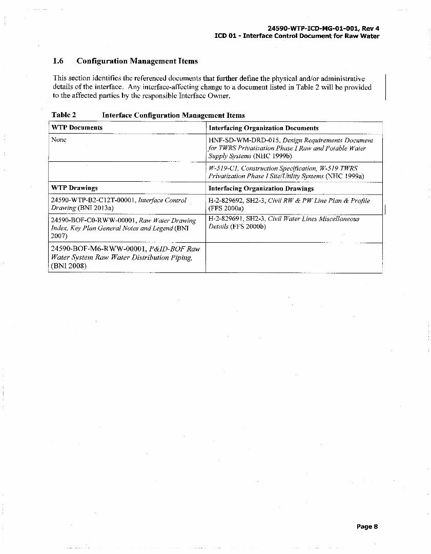
1.6 Configuration Management Items
24590-WTP-ICD-MG-01-001, Rev 4 ICD 01 - Interface Control Document for Raw Water
This section identifies the referenced documents that further define the physical and/or administrative details of the interface. Any interface-affecting change to a document listed in Table 2 will be provided to the affected parties by the responsible Interface Owner.
Table2 Interface Configuration Management Items
WTP Documents Interfacing Organization Documents
None HNF-SD-WM-DRD-015, Design Requirements Document for TWRS Privatization Phase I Raw and Potable Water Supply Systems (NHC l 999b)
W-519-CI, Construction Specification, W-519 TWRS Privatization Phase I Site/Utility Systems (NHC 1999a)
WTP Drawings Interfacing Organization Drawings
24590-WTP-B2-Cl2T-00001, Interface Control H-2-829692, SH2-3, Civil RW & PW Line Plan & Profile Drawing (BNI 2013a) (FFS 2000a)
24590-BOF-CO-RWW-00001, Raw Water Drawing H-2-829691, SH2-3, Civil Water Lines Miscellaneous
Index, Key Plan General Notes and Legend (BNI Details (FFS 2000b)
2007)
24590-BOF-M6-RWW-00001, P&ID-BOF Raw Water System Raw Water Distribution Piping, (BNI 2008)
Pages
24590-WTP-ICD-MG-01-001, Rev 4 ICD 01 - Interface Control Document for Raw Water
2 References
BNI. 2003a. Memorandum: Document Review Request-Interface for the Hanford Site Water Purveyor's Approval of Raw Water Specification and Drawings, CCN 063409. August 2003. Bechtel National, Inc., Richland, WA, USA.
BNI. 2003b. Memorandum from Robert Gibbs to Kevin Cleveland, Raw Water Sample Results.from September, October, and December 2002 Sample Events, CCN 051775. 18 February 2003. Bechtel National, Inc., Richland, WA, USA.
BNI. 2007. Raw Water Drawing Index, Key Plan General Notes and Legend, 24590-BOF-CO-RWW-00001, Rev 2. June 2007. Bechtel National, Inc., Richland, WA, USA.
BNI. 2008. P&ID-BOF Raw Water System Raw Water Distribution Piping, 24590-BOF-M6-RWW-00001, Rev 3. April 2008. Bechtel National, Inc., Richland, WA, USA.
BNI. 2010. Hanford Potable Water, CCN 215884. March 2010. Bechtel National, Inc., Richland, WA, USA.
BNI. 2013a. Interface Control Drawing, 24590-WTP-B2-C12T-00001, Rev 2. June 2013. Bechtel National, Inc., Richland, WA, USA.
BNI. 2013b. Design Pressure and Temperature Calculation for Raw Water (RWW) System, 24590-BOF-M6C-RWW-00001, Rev 1. October 2013. Bechtel National, Inc., Richland, WA, USA.
BNI. 2013c. Maximum and Minimum Allowable Raw Water Pressures at WTP, CCN 260803. October 2013. Bechtel National, Inc., Richland, WA, USA.
DOE. 1995. State Waste Discharge Permit Application - Hydrotest, Maintenance and Construction Discharges, DOEIRL-95-93, Rev 0. November 1995. US Department of Energy, Richland, WA, USA.
Ecology. 2005. State Waste Discharge Permit, Permit No. ST 4511. February 2005. Washington State Department of Ecology, Kennewick, WA, USA.
FFS. 2000a. Civil RW & PW Line Plan & Profile, H-2-829692, Sheets 2 (Rev 1) and 3 (Rev 1). April 2000. Fluor Federal Services, Richland, WA, USA.
FFS. 2000b. Civil Water Lines Miscellaneous Details, H-2-829691, Sheets 2 (Rev 1) and 3 (Rev 3), April 2000 (Sheet 2) and October 2000 (Sheet 3). Fluor Federal Services, Richland, WA, USA.
FFS. 2002. 200 Area Raw Water System Network Analysis in Support of WTP Project, RPP-6672, Rev 1. March 2002. Fluor Federal Services, Richland, WA, USA.
FH. 2003. Correspondence No. FH-0300728A Rl, Water Service to the Waste Treatment Plant (WTP) Department of Health (DOH) Request for Information, dated March 04, 2003. Fluor Hanford, Richland, WA, USA.
NHC. 1999a. Construction Specification, W-519 TWRS Privatization Phase I Site/Utility Systems, W-519-Cl, Rev 0. April 1999. Numatec Hanford Corporation, Richland, WA, USA.
Page9
24590-WTP-ICD-MG-01-001, Rev 4 ICD 01 - Interface Control Document for Raw Water
NHC. 1999b. Design Requirements Document for TWRS Privatization Phase I Raw and Potable Water Supply Systems, HNF-SD-WM-DRD-015, Rev 1. December 1998. Numatec Hanford Corporation, Richland, WA, USA.
NHC. 1999c. TWRS Privatization Phase I Infrastructure Project W-519 Available Data on 200 Area Raw Water Composition, NHC-9950503 (CCN 001808). 3 February 1999. Numatec Hanford Corporation, Richland, WA, USA.
NFPA 22. 2008. Standard for Water Tanks for Private Fire Protection, National Fire Protection Association, 2008 Edition.
NFPA 24. 1995. Standard for the Installation of Private Fire Service Mains and Their Appurtenances, National Fire Protection Association, 1995 Edition.
USGS. 1997. Water Resources Data Washington Water Year 1997, Water-Data Report WA-97-1. US Geological Survey.
WAC 246-290-490. 2003. "Cross-Connection Control", Public Water Supplies, Washington Administrative Code.
Page 10
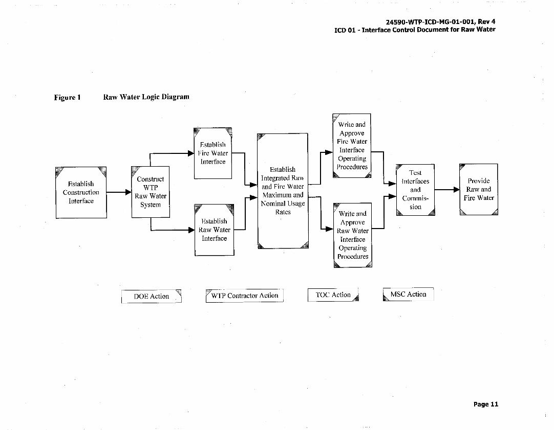
Figure 1
Establish Construction
Interface
Raw Water Logic Diagram
.------.. •.ii Fire Water Interface
Construct WTP
Raw Water System
Interface
Establish Integrated Raw and Fire Water Maximum and Nominal Usage
Rates
DOEAction , r WTP Contractor Action
24590-WTP-ICD-MG-01-001, Rev 4 ICD 01 - Interface Control Document for Raw Water
TOC Action]
Test Interfaces
and
lMSCAction
Provide Raw and
Page 11
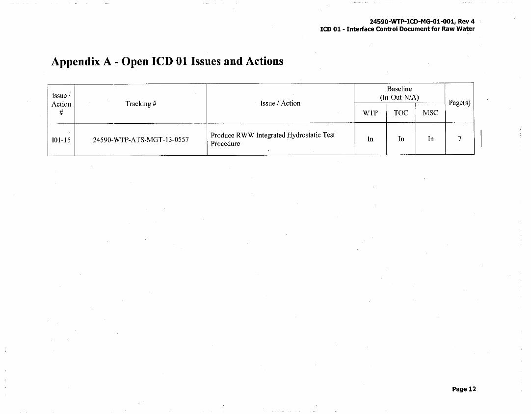
Appendix A - Open ICD 01 Issues and Actions
Issue I Action Tracking# Issue I Action
#
24590-WTP-ICD-MG-01-001, Rev 4 ICD 01 - Interface Control Document for Raw Water
Baseline (In-Out-NIA)
Page(s)
WTP TOC MSC
101-15 24590-WTP-ATS-MGT-13-0557 Produce RWW Integrated Hydrostatic Test
In In In 7 Procedure
Page 12
24590-WTP-ICD-MG-01-001, Rev 4 ICD 01 - Interface Control Document for Raw Water
Appendix B - ICD 01 Issues and Actions Closed Since Last Revision
Issue I Date
Action Tracking# Issue I Action Closed
Resolution #
None
Page 13
Appendix C - ICD 01 Open Items List
24590-WTP-ICD-MG-01-001, Rev 4 ICD 01- Interface Control Document for Raw Water
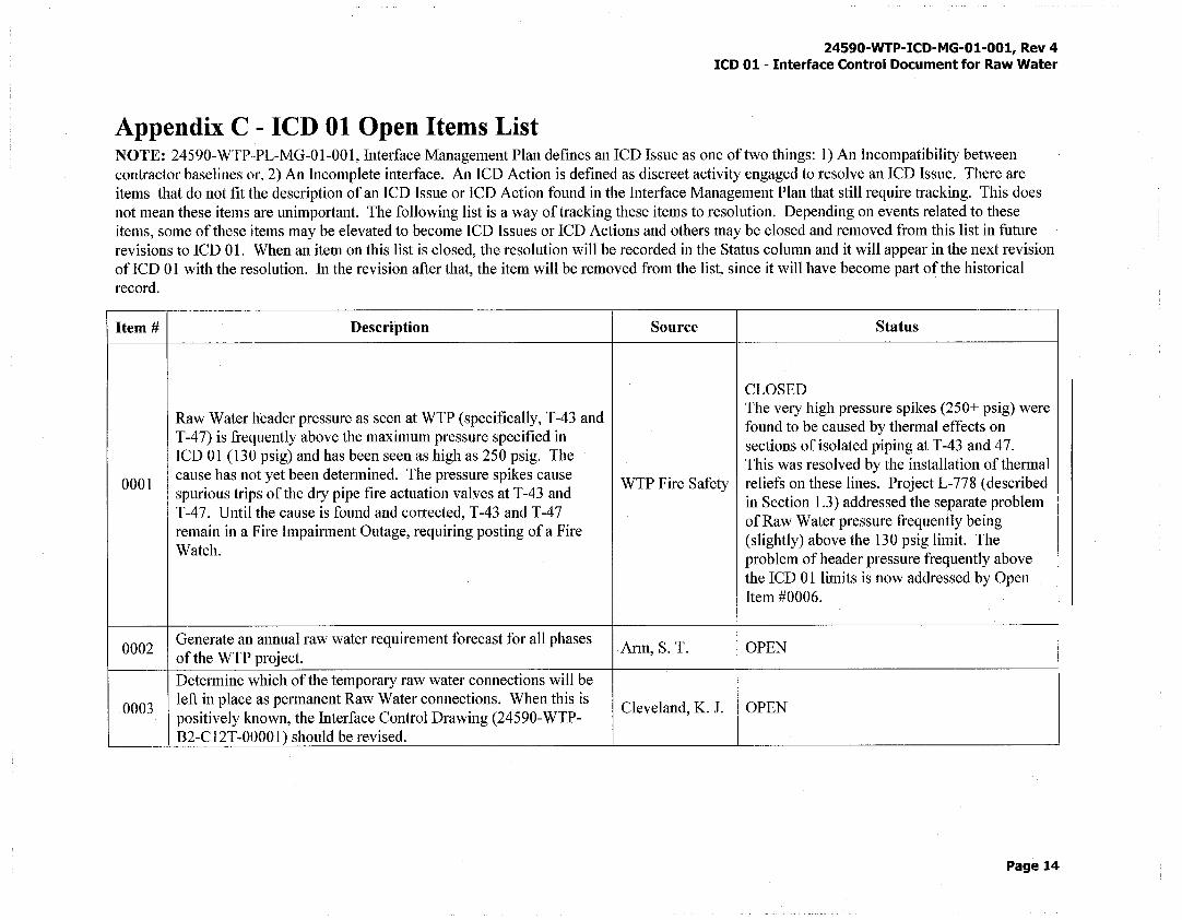
NOTE: 24590-WTP-PL-MG-01-001, Interface Management Plan defines an ICD Issue as one of two things: 1) An Incompatibility between contractor baselines or, 2) An Incomplete interface. An ICD Action is defined as discreet activity engaged to resolve an ICD Issue. There are items that do not fit the description of an ICD Issue or ICD Action found in the Interface Management Plan that still require tracking. This does not mean these items are unimportant. The following list is a way of tracking these items to resolution. Depending on events related to these items, some of these items may be elevated to become ICD Issues or ICD Actions and others may be closed and removed from this list in future revisions to ICD 01. When an item on this list is closed, the resolution will be recorded in the Status column and it will appear in the next revision ofICD 01 with the resolution. In the revision after that, the item will be removed from the list, since it will have become part of the historical record.
Item# Description Source Status
CLOSED
Raw Water header pressure as seen at WTP (specifically, T-43 and The very high pressure spikes (250+ psig) were found to be caused by thermal effects on
T-4 7) is frequently above the maximum pressure specified in sections of isolated piping at T-43 and 4 7.
ICD 01 (130 psig) and has been seen as high as 250 psig. The This was resolved by the installation of thermal
0001 cause has not yet been determined. The pressure spikes cause
WTP Fire Safety reliefs on these lines. Project L-778 (described spurious trips of the dry pipe fire actuation valves at T-43 and
in Section 1.3) addressed the separate problem T-47. Until the cause is found and corrected, T-43 and T-47
of Raw Water pressure frequently being remain in a Fire Impairment Outage, requiring posting of a Fire
(slightly) above the 130 psig limit. The Watch.
problem of header pressure frequently above the ICD 01 limits is now addressed by Open Item #0006.
0002 Generate an annual raw water requirement forecast for all phases
Arm, S. T. OPEN of the WTP project.
Determine which of the temporary raw water connections will be
0003 left in place as permanent Raw Water connections. When this is
Cleveland, K. J. OPEN positively known, the Interface Control Drawing (24590-WTP-B2-C12T-00001) should be revised.
Page 14
Item# Description
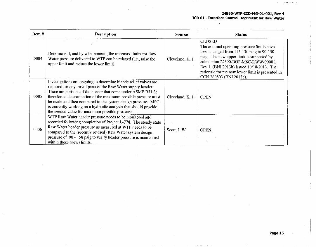
Determine if, and by what amount, the min/max limits for Raw 0004 Water pressure delivered to WTP can be relaxed (i.e., raise the
upper limit and reduce the lower limit).
Investigations are ongoing to determine if code relief valves are required for any, or all parts of the Raw Water supply header. There are portions of the header that come under ASME B3 l .3;
0005 therefore a determination of the maximum possible pressure must be made and then compared to the system design pressure. MSC is currently working on a hydraulic analysis that should provide the needed value for maximum possible pressure. WTP Raw Water header pressure needs to be monitored and recorded following completion of Project L-778. The steady state
0006 Raw Water header pressure as measured at WTP needs to be compared to the (recently revised) Raw Water system design pressure of 90 - 150 psig to verify header pressure is maintained within these (new) limits.
24590-WTP-ICD-MG-01-001, Rev 4 ICD 01 - Interface Control Document for Raw Water
Source Status
CLOSED The nominal operating pressure limits have been changed from 115-130 psig to 90-150 psig. The new upper limit is supported by
Cleveland, K. J. calculation 24590-BOF-M6C-RWW-00001, Rev 1, (BNI 2013b) issued 10/10/2013. The rationale for the new lower limit is presented in CCN 260803 (BNI 2013c).
Cleveland, K. J. OPEN
Scott, J. W. OPEN
Page 15