ic design for wireless system - guceee.guc.edu.eg/courses/electronics/elct910 ic for wireless...
TRANSCRIPT

1
IC design for wireless system
Dr. Ahmed H. [email protected]
Lecture 1
Dr. Ahmed H. Madian-IC for wireless systems 22
Course Objective
� To bridge the gap between the circuit and system visions in wireless design.
� To build up low frequency integrated circuit operations increasing complexity to high frequency circuits such as Low-noise amplifiers, mixers, analog-to-digital converters, VCOs and local oscillators.
Dr. Ahmed H. Madian-IC for wireless systems 33
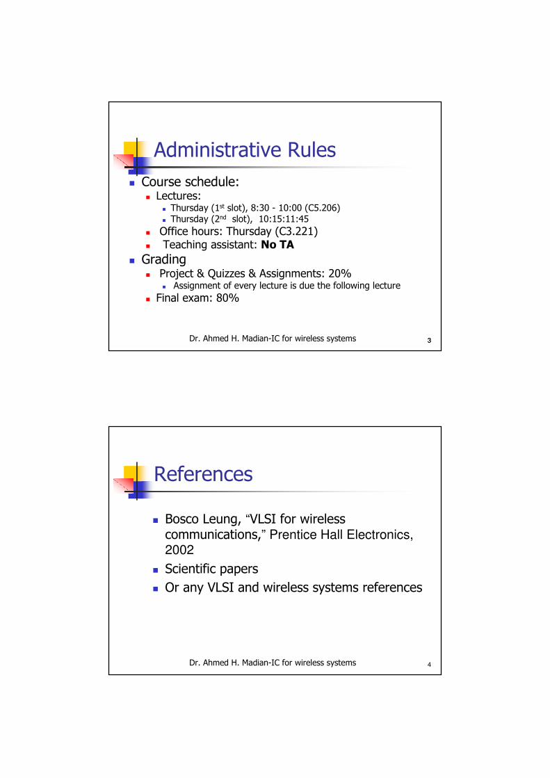
Administrative Rules
� Course schedule:� Lectures:
� Thursday (1st slot), 8:30 - 10:00 (C5.206) � Thursday (2nd slot), 10:15:11:45
� Office hours: Thursday (C3.221)� Teaching assistant: No TA
� Grading� Project & Quizzes & Assignments: 20%
� Assignment of every lecture is due the following lecture
� Final exam: 80%
Dr. Ahmed H. Madian-IC for wireless systems 4
References
� Bosco Leung, “VLSI for wireless communications,” Prentice Hall Electronics,
2002
� Scientific papers
� Or any VLSI and wireless systems references

Dr. Ahmed H. Madian-IC for wireless systems 55
Course outline
� Overview of Wireless communication systems
� Low-noise amplifiers
� Local Oscillators
� Mixers
� Analog to digital Converters
� Frequency synthesizer
� High-speed digital circuits
Dr. Ahmed H. Madian-IC for wireless systems 6
Wireless History
� Guglielmo Marconi invented the wireless telegraph in 1896
� Communication by encoding alphanumeric characters in analog signal –continuous wave (CW)
� Sent telegraphic signals across the Atlantic Ocean
� “It is dangerous to put limits on Wireless” - Guglielmo Marconi, 1932
� Communications satellites launched in 1960s
� Advances in wireless technology
� Radio, television, mobile telephone, communication satellites – initially RF based analog systems in the VHF/UHF spectrum
� More recently
� Satellite communications, wireless networking, cellular technology –digital RF in the microwave spectrum
Dr. Ahmed H. Madian-IC for wireless systems 77
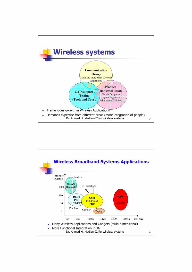
Wireless systems
� Tremendous growth in Wireless Applications
� Demands expertise from different areas (more integration of people)
Communication
TheoryMath and more Math (Greek!)
Algorithms
Product
ImplementationCircuit Designers
Layout Engineers
Microwave/DSP..etc
CAD support
Testing
(Tools and Toys!)
Dr. Ahmed H. Madian-IC for wireless systems 8
Wireless Broadband Systems Applications
� Many Wireless Applications and Gadgets (Multi-dimensional)
� More Functional Integration in 3G
WLAN
Bluetooth
DECT
PHS
CT1/CT2
GSM
IS-54/IS-95
PDC
Paging
GPS
Satalite
Bit Rate
KB/Sec
1000
100
10
1
10m 100m 1000m 10Km 100Km 1000Km
In-door
3G directions
CordlessCellular
Cell Size
Dr. Ahmed H. Madian-IC for wireless systems 9
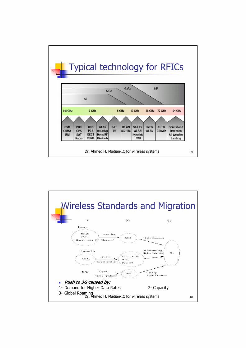
Typical technology for RFICs
Dr. Ahmed H. Madian-IC for wireless systems 10
Wireless Standards and Migration
� Push to 3G caused by:
1- Demand for Higher Data Rates 2- Capacity
3- Global Roaming

Dr. Ahmed H. Madian-IC for wireless systems 11
Third Generation Cell Phones
� Multi-dimensional applications and Multi-standard support
3G demands
More Capacity
Higher data rates
More Functions
Backward Compatability
Global Roaming
Lower Cost
Small Size
Long Battery
lifetime
Programmable CMOS Integrated Wireless Transceivers
WCDMA (5MHz) Multi-Standard
(Programmable)
Low Power
CMOS solution
Dr. Ahmed H. Madian-IC for wireless systems 12
General RF Transceiver Architecture
� RF Section – analog high frequencies
� Baseband Section-mostly digital ICs working at low frequency

Dr. Ahmed H. Madian-IC for wireless systems 13
General RF Transceiver
� RF Transmitter
� RF Receiver
Dr. Ahmed H. Madian-IC for wireless systems 14
Optimal RF Transceiver

Dr. Ahmed H. Madian-IC for wireless systems 15
Types of wireless receivers
Dr. Ahmed H. Madian-IC for wireless systems 16
Wireless Receivers from a Digital/Analog Perspective
� Depends on ADC location in the Analog front End� An All digital receiver demands RF-ADC (not practical with current technology)
� IF Sampling is currently an active research topic
Wireless Receivers
ADC at RF
ADC at IF
ADC at Baseband
Super Heterodyne
Zero-IF
Low-IF
Wideband IF double
conversion

Dr. Ahmed H. Madian-IC for wireless systems 17
Super Heterodyne Receivers
� Discrete IR and IF filters not amenable for Integration
� Channel selection done at IF
� Low dynamic range baseband circuits
� Multi-Standard programmability in IF stage is difficult to achieve
Dr. Ahmed H. Madian-IC for wireless systems 18
Integrated Receivers
� Eliminates the need for discrete IR and IF filters
� Signal + Blockers are translated to baseband
� Channel selection done at baseband
� High dynamic range baseband circuits required
� Multi-standard programmability in baseband circuits

Dr. Ahmed H. Madian-IC for wireless systems 19
Direct Conversion Receiver
� Digital servo loop implementation using DSP (for offset cancellation)
� Baseband Filter programmability for multi-standard support
� Digitally programmable variable gain amplifiers
Dr. Ahmed H. Madian-IC for wireless systems 20
programmable baseband chain for a multistandard receiver (ex.:GSM/DECT )
� Enables cell phones to be used as a cordless phone by supportingboth GSM/DECT modes of operation
� Utilizes wide band double conversion technique to allow integration
� Focus set to develop the baseband section of the receiver chain

Dr. Ahmed H. Madian-IC for wireless systems 21
GSM/DECT multi-standard receiver
� DC offset cancellation in DSP
� DC offset fed back to baseband section to be subtracted from signal
� VGA with digital offset correction capability is preferred
� Channel selection to be performed using DSP
� Relaxes filtering requirements
� Software programmable FIR filters for multistandard operation
� Requires the use of high dynamic range sigma delta converter
� Baseband VGA to reduce the ADC dynamic range
Dr. Ahmed H. Madian-IC for wireless systems 22
Baseband Circuits for Integrated receivers
� Filtering/Amplification relaxes ADC dynamic range
� Low Noise/High Linearity

Dr. Ahmed H. Madian-IC for wireless systems 23
Baseband Circuit Design
� “Integrated receivers lead to challenging demands on baseband circuits”
� Small gain in RF section� Wide gain control in baseband VGA
� Low baseband input referred noise
� Out of Band Blockers translated directly to baseband
� Good Linearity in Amplifiers/Filters
� Most of Filtering operation done in baseband section
� DC offset problem
� Wide signal bandwidth (Low power??)
Dr. Ahmed H. Madian-IC for wireless systems 24
Challenges in the Wireless Challenges in the Wireless
Comm. Revolution:Comm. Revolution:
• Power Consumption
• Multiplicity of Standards
• Requirement for Linear PA
• External Component Count
• Higher Frequency of Operation
• Time to Market
Dr. Ahmed H. Madian-IC for wireless systems 25
Power ConsumptionPower Consumption
� Mobile applications require very low power
� Cellular transceivers burn ~ 100mW of power while power amplifiers burn several watts
� Talk time limited by PA and DSP to a few hours (today we can safely ignore transceiver power!)
� In the future the PA power will drop significantly (power control will regulate power to low levels)
� Transceiver power will thus become equally important
� Transceivers today designed for worst-case scenario of distant base station in presence of nearby interferers
Dr. Ahmed H. Madian-IC for wireless systems 26
Dynamic TransceiversDynamic Transceivers
� High power consumption comes about due to simultaneous requirement of high linearity in RF front-end and low noise operation
� The conflicting requirements occur since the linearity of the RF front-end is exercised by a strong interferer while trying to detect a weak signal
� A dynamic transceiver can schedule gain/power of the front-end for optimal performance
Dr. Ahmed H. Madian-IC for wireless systems 27
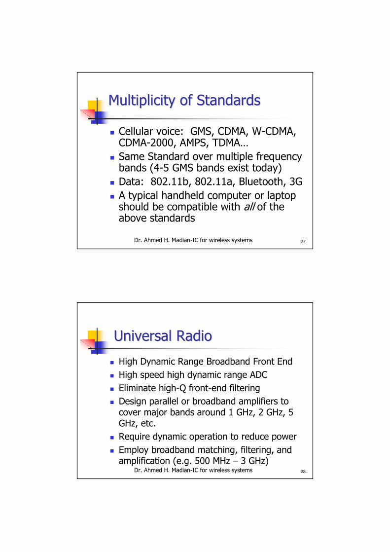
Multiplicity of StandardsMultiplicity of Standards
� Cellular voice: GMS, CDMA, W-CDMA, CDMA-2000, AMPS, TDMA…
� Same Standard over multiple frequency bands (4-5 GMS bands exist today)
� Data: 802.11b, 802.11a, Bluetooth, 3G
� A typical handheld computer or laptop should be compatible with all of the above standards
Dr. Ahmed H. Madian-IC for wireless systems 28
Universal RadioUniversal Radio
� High Dynamic Range Broadband Front End
� High speed high dynamic range ADC
� Eliminate high-Q front-end filtering
� Design parallel or broadband amplifiers to cover major bands around 1 GHz, 2 GHz, 5 GHz, etc.
� Require dynamic operation to reduce power
� Employ broadband matching, filtering, and amplification (e.g. 500 MHz – 3 GHz)
Dr. Ahmed H. Madian-IC for wireless systems 29
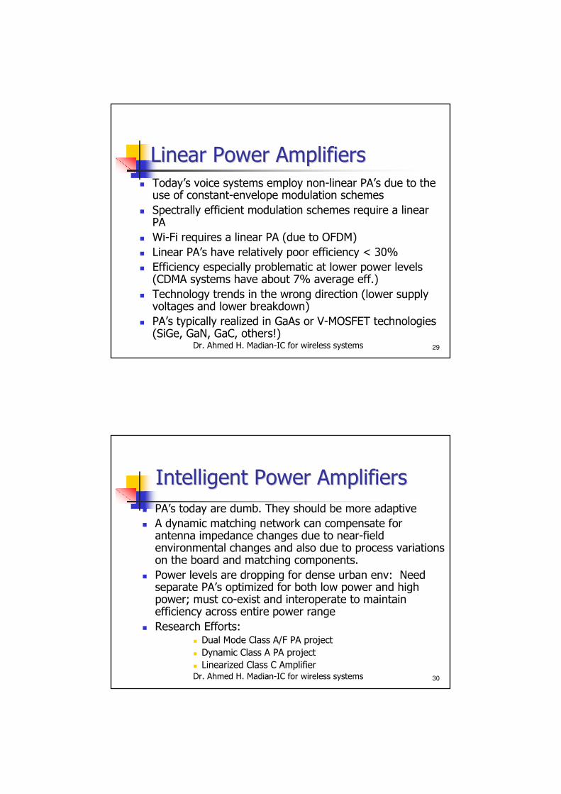
Linear Power AmplifiersLinear Power Amplifiers� Today’s voice systems employ non-linear PA’s due to the use of constant-envelope modulation schemes
� Spectrally efficient modulation schemes require a linear PA
� Wi-Fi requires a linear PA (due to OFDM)
� Linear PA’s have relatively poor efficiency < 30%
� Efficiency especially problematic at lower power levels (CDMA systems have about 7% average eff.)
� Technology trends in the wrong direction (lower supply voltages and lower breakdown)
� PA’s typically realized in GaAs or V-MOSFET technologies (SiGe, GaN, GaC, others!)
Dr. Ahmed H. Madian-IC for wireless systems 30
Intelligent Power AmplifiersIntelligent Power Amplifiers
� PA’s today are dumb. They should be more adaptive
� A dynamic matching network can compensate for antenna impedance changes due to near-field environmental changes and also due to process variations on the board and matching components.
� Power levels are dropping for dense urban env: Need separate PA’s optimized for both low power and high power; must co-exist and interoperate to maintain efficiency across entire power range
� Research Efforts:� Dual Mode Class A/F PA project
� Dynamic Class A PA project
� Linearized Class C Amplifier
Dr. Ahmed H. Madian-IC for wireless systems 31
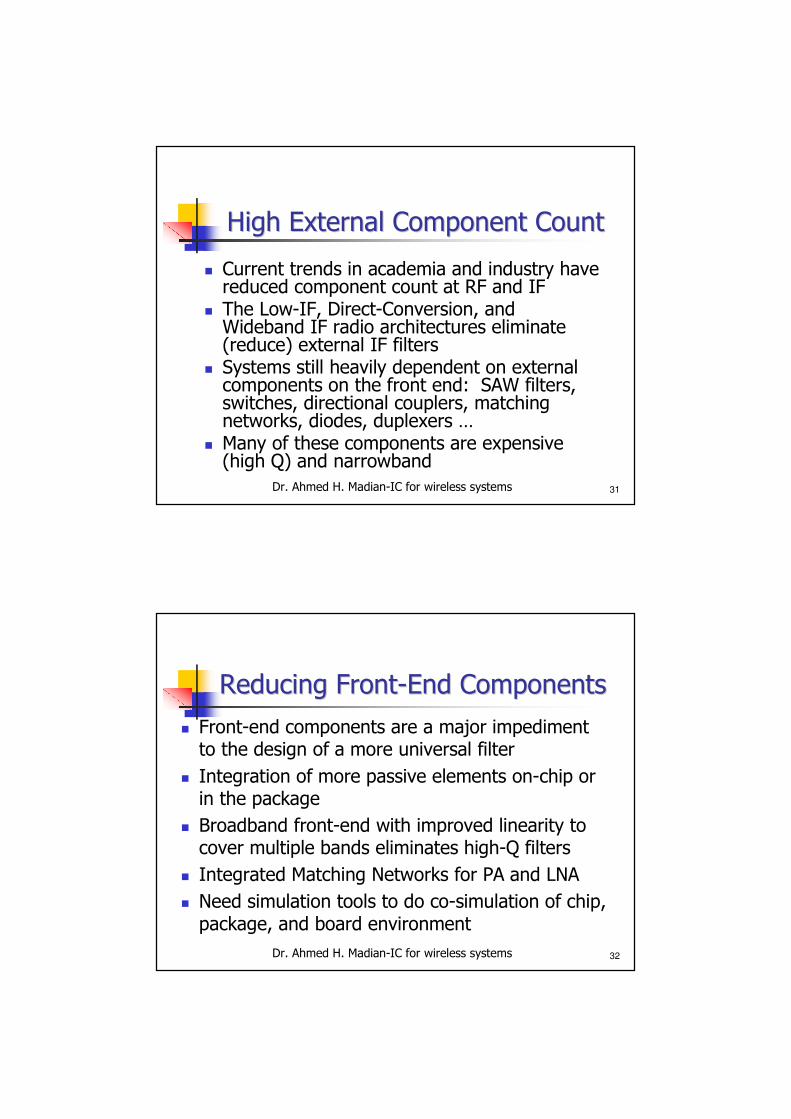
High External Component CountHigh External Component Count
� Current trends in academia and industry have reduced component count at RF and IF
� The Low-IF, Direct-Conversion, and Wideband IF radio architectures eliminate (reduce) external IF filters
� Systems still heavily dependent on external components on the front end: SAW filters, switches, directional couplers, matching networks, diodes, duplexers …
� Many of these components are expensive (high Q) and narrowband
Dr. Ahmed H. Madian-IC for wireless systems 32
Reducing FrontReducing Front--End ComponentsEnd Components
� Front-end components are a major impediment to the design of a more universal filter
� Integration of more passive elements on-chip or in the package
� Broadband front-end with improved linearity to cover multiple bands eliminates high-Q filters
� Integrated Matching Networks for PA and LNA
� Need simulation tools to do co-simulation of chip, package, and board environment
Dr. Ahmed H. Madian-IC for wireless systems 33
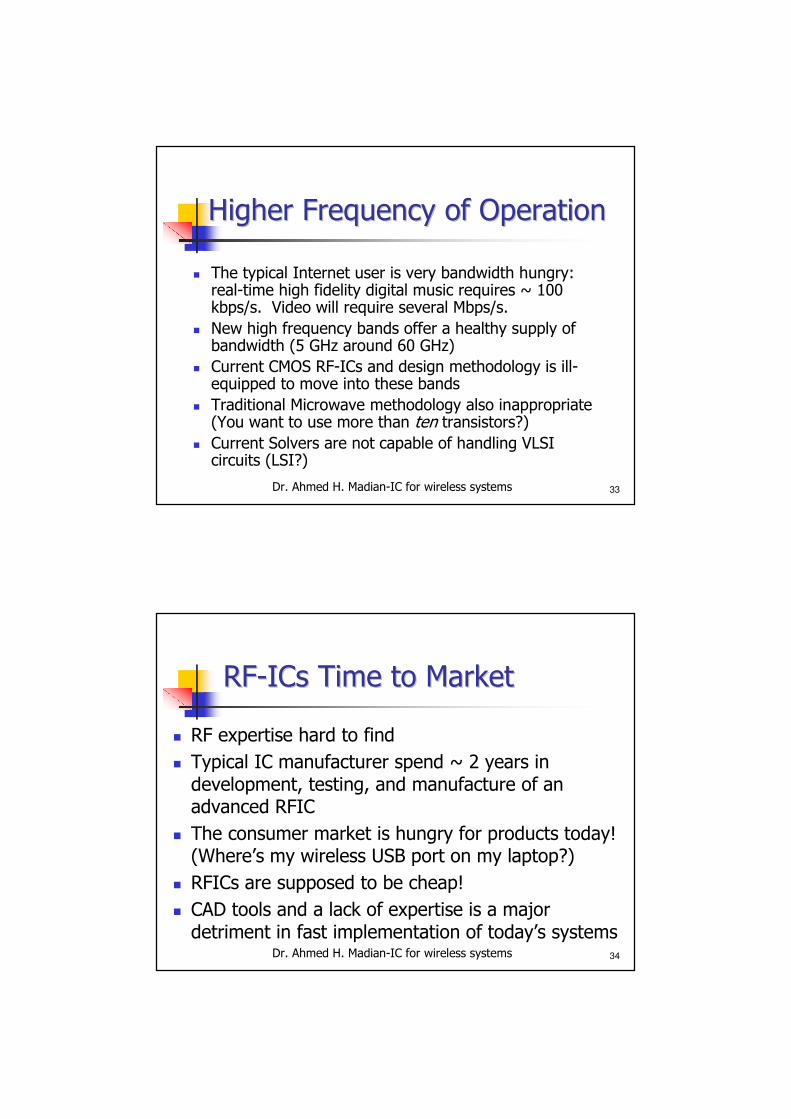
Higher Frequency of OperationHigher Frequency of Operation
� The typical Internet user is very bandwidth hungry: real-time high fidelity digital music requires ~ 100 kbps/s. Video will require several Mbps/s.
� New high frequency bands offer a healthy supply of bandwidth (5 GHz around 60 GHz)
� Current CMOS RF-ICs and design methodology is ill-equipped to move into these bands
� Traditional Microwave methodology also inappropriate (You want to use more than ten transistors?)
� Current Solvers are not capable of handling VLSI circuits (LSI?)
Dr. Ahmed H. Madian-IC for wireless systems 34
RFRF--ICs Time to MarketICs Time to Market
� RF expertise hard to find
� Typical IC manufacturer spend ~ 2 years in development, testing, and manufacture of an advanced RFIC
� The consumer market is hungry for products today! (Where’s my wireless USB port on my laptop?)
� RFICs are supposed to be cheap!
� CAD tools and a lack of expertise is a major detriment in fast implementation of today’s systems
Dr. Ahmed H. Madian-IC for wireless systems 35
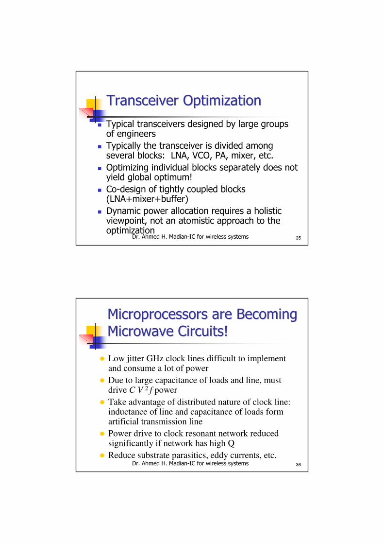
Transceiver OptimizationTransceiver Optimization
� Typical transceivers designed by large groups of engineers
� Typically the transceiver is divided among several blocks: LNA, VCO, PA, mixer, etc.
� Optimizing individual blocks separately does not yield global optimum!
� Co-design of tightly coupled blocks (LNA+mixer+buffer)
� Dynamic power allocation requires a holistic viewpoint, not an atomistic approach to the optimization
Dr. Ahmed H. Madian-IC for wireless systems 36
Microprocessors are Becoming Microprocessors are Becoming
Microwave Circuits!Microwave Circuits!
� Low jitter GHz clock lines difficult to implement and consume a lot of power
� Due to large capacitance of loads and line, must drive C V 2 f power
� Take advantage of distributed nature of clock line: inductance of line and capacitance of loads form artificial transmission line
� Power drive to clock resonant network reduced significantly if network has high Q
� Reduce substrate parasitics, eddy currents, etc.
Dr. Ahmed H. Madian-IC for wireless systems 37Dr. Ahmed H. Madian-VLSI 37
Thanks
Dr. Ahmed H. Madian-IC for wireless systems 38
Refernces
� Dr. H.O Elwan PhD Presentations