ibm system/370 model 158 functional …chiclassiccomp.org/docs/content/computing/ibm/mainframe/...6...
TRANSCRIPT

( I \_)
i' i
Systems
GA22-7011-4 File No. S/370-01
IBM System/370 Model 158 Functional Characteristics

Preface
This manual describes the functional characteristics and features of the IBM System/370 Model 158. It provides ~anagement, programming, and operations personnel experienced in System/370 operation with a fundamental understanding of the Model 158. IBM System/370 Principles of Operation, GA22-7000, is referenced throughout the text and should be used in conjunction with this publication.
covers the central processing unit and storage functions, the system console, the console display, and the IBM 3213 Console Printer, as well as a summary of standard facilities and optional features. A section, "Hierarchical Monitoring System," has been added under "System Console."
Only information that is of particular concern to the Model 158 user is discussed in this manual. Discussion
Detailed information on channel characteristics for System/370 Model 158 is available in IBM System/370 Model 158 Channel Characteristics, GA22-7012.
Fifth Edition (April 1976) This is a reprint of GA22-701 l-3 incorporating changes released in the following Technical Newsletter:
GN22-0504 (dated December 17, 197 5)
Changes are periodically made to the information herein; before using this publication in connection with the operation of IBM equipment, refer to the/BM System/370 Bibliography, GC20-0001, for editions that are applicable and current.
Requests for copies of IBM publications should be made to your IBM representative or to the IBM branch office serving your locality.
This manual has been prepared by the IBM System Products Division, Product Publications, Dept. B98, PO Box 390, Poughkeepsie, N.Y. 12602. A form for readers' comments is provided at the back of this publication. If the form has been removed, comments may be sent to the above address. Comments become the property of IBM.
©Copyright International Business Machines Corporation 1972, 1973
- -
(\ I

Contents
v Introduction 5 Bezel Indicators 18 Virtual Storage 5 Display Frames 18 Multi processing 5 Hierarchical Monitoring System 23 Programming Support 5 IBM 3 213 Console Printer . 24 Compatibility 5 Printer Controls and Indicators 24 Remote Support Facility 5 Operator Controls 24 Standard Facilities and Optional Features 7 Forms Specifications 24
Central Processing Unit . 9 Programmed Operations 25 Instruction Fetch (I-Fetch) 9 Display Mode 25 Instruction Retry 9 Control Characters . 25 Error Checking 9 Selector Pen Detection 25 Timing Facilities 9 Console Commands 27 Machine Check Interruptions 9 Order Sequences 29 Resets 10 Status and Sense Information 30 Reloadable Control Storage (RCS) 10 Interruptions 31 Loe.al Storage 10 Printer-Keyboard Mode 32 Main Storage 10 Commands 32 Buff er Storage and Index Array 10 Status and Sense Information 33 Virtual Storage 11 Storage Allocation 11 Facilities and Features Summary 35 Translation Lookaside Buffer (TLB) 11 Standard Facilities 35 Reference and Change Recording 11 System/370 Universal Instruction Set 35 Channel Operations 11 Dynamic Address Translation 35 Program Event Recording 12 Clock Comparator 35 Store Status Facility 12 CPU Timer 35 System Mask Changes 12 Command Retry 35
Channel Retry 35 System Console 13 First Byte and Block Multiplexer Channels 35 Remote System Consol1::l 13 Optional Features 36 Console Support 13 Direct Control 36 Display Mode Considerations 13.1 Channel-to-Channel Adapter 36
Cursor 13.1 Emergency Power-off Control (Multisystem) 36 Console Buff er 13.1 Extended-precision Floating-point 36 Data Fields 13.1 OS/DOS CompatibHity 36
Control Panel 14 1401/1440/1460 and 1410/7010 Compatibility 36 Emergency Pull Switch 14 7070/7074 Compatibility 36 Power-on Pushbutton 14 Virtual Machine Assist Feature 36 Power-off Pushbutton 14 Power Warning Feature 37 TOD Clock Switch 14 Integrated Storage Controls (ISC) 37 .1 IMPL Pushbutton 14 Multiprocessing . 39 Lamp Test Pushbutton 15 Configuration Control Panel 41 Remote/Local Clock Switch and Remote Clock System Control Panel Features 43
Indicator 15 Remote Pushbutton/Indicator 15 Power Check Indicator 15 Appendix A. EBCDIC Interface Code 44
Keyboard 15 Alphameric Keys 15 Appendix B. Instruction Times for System/370 Cursor Control Keys 15 Model 158 45
~ Function Keys 16 Console Display 16 Appendix C. Glossary and Abbreviations 57
Intensity Controls 18
• Security Key 18 Index 59

IBM System/370 Model 158
....
)

u
The IBM System/370 Model 158 is a medium-size, high performance data processing system that extends and enhances the basic System/370 concept. The Model 158 incorporates many new features including integrated monolithic main storage, virtual storage capability, enhanced timing facilities, integrated storage controls, and a display console. These improved functional capabilities encourage expanded applications for all large-scale users.
The basic components of the System/370 Model 158 are the CPU (the IBM 3158 Processing Unit), the display console, and an optional console printer. Included within the 3158 are the processor, main storage, buffer storage, at least one byte-multiplexer channel, and two blockmultiplexer channels. Input/output (I/O) devices are attached to the channels via control units.
The 3158 is available in six main storage capacities:
Model 1 Model 3 Main Storage Capacity
I and MPl J and MP2 JI and MP3 Kand MP4 KJ and MPS Land MP6
U31 and M31 U32 and M32 U33 and M33 U34 and M34 U35 and M35 U36 and M36
524,288 bytes (512K) 1,048,576 bytes (1,024K) 1,572,864 bytes (l,536K) 2,097,152 bytes (2,048K) 3,145 ,728 bytes (3,072K) 4,194,304 bytes (4,096K)
A high-speed buffer is standard; its storage capacity is 8,192 bytes (8K) in the Model 1, and 16,384 bytes (16K) in the Model 3.
The Model 3 is an advanced version of the Model 1 which can be converted to a Model 3. Information within this manual applies to both models unless noted otherwise. Differences between the two are discussed where relevant.
For input/output operations, one byte-multiplexer channel (channel 0) and two block-multiplexer channels (channels 1 and 2) are standard. Optional features provide for up to three additional block-multiplexer channels (channels 3, 4, and 5). Alternatively, with channel 3 installed, channel 4 may be utilized as a second bytemultiplexer channel. For details refer to the configurator, Figure 1.
VIRTUAL STORAGE
Regardless of the real storage capacity, when the Model 158 is operating in ex tended control (EC) mode with dynamic address translation invoked, all logical addresses within the 24-bit addressing scheme of System/370 are available. Therefore, the maximum logical (virtual) address is 16,777,215. System/370 Model 158 is designed primarily to support this virtual storage environment; it is not subject to restraints normally imposed on programming applications by the amount of available storage, and the operational flexibility of the installation is enhanced.
Introduction
MULTIPROCESSING
Multiprocessing is a logical extension of multiprogramming. A Model 158 Multiprocessing System uses two multiprocessing (MP) versions of the 3158, joined by an IBM 3058 Multisystem Unit. The CPUs can execute programs simultaneously while sharing total system resources, including data. Benefits derived from multiprocessing include operational efficiency and flexibility and improved system availability. The most critical component of the MP system is the control program; CPUs are considered to be a system resource the same as I/O devices and storage.
PROGRAMMING SUPPORT
Programming support for extended control (EC) mode with dynamic address translation (DAT) is provided by OS/VS 1, OS/VS2, VM/370, and DOS/VS. Programming support for multiprocessing is provided by OS/VS2, Release 2.
In addition, OS/360 and DOS/360 (in hardstop mode) provide support in System/370 basic control (BC) mode.
COMPATIBILITY
The Model 158 is upward program compatible with models of IBM System/360 and System/370. All programs written for System/360 and System/370 will operate on the Model 158 with the following exceptions: 1. Time-dependent programs. 2. Programs deliberately written to cause program checks. 3. Programs using machine-dependent data (for example,
machine logs). 4. Programs using the ASCII bit. 5. Programs that depend on the contents of the extended
logout area(decimal 128-1152 for the Model 158). 6. Programs that depend on devices or architecture not
implemented in the Model 158. 7. Programs using any other model-dependent functions as
specified in IBM System/370 Principles of Operation, GA22-7000.
8. In EC mode, programs that modify CCWs during channel program execution.
REMOTE SUPPORT FACILITY
In the event of system malfunction, this facility provides the customer with the combined expertise of local and remote IBM System/370 Model 158 support specialists. This is achieved by linking the system via a teleprocessing network to the field technical support center. The advan· tages of this support technique are evident; however, the customer's data security and privacy are subject to some exposure while the remote support facility is in use.
Introduction 5

3158-1
3158-3
IBM 3158 Processing Unit
Model l Units
I J JI K KJ L
Channel 0
MPl MP2 MP3 MP4 MP5 MP6
O* Non sharing Nonsharing Option**
256
Without Sharing
256
Nonshared Option•·•
120
Byte Multiplexer Subchannels per Channel 0 or 4
With Sharing
256
Channel 4* Sharing Option
Nonshared Shared
120
480* 32* or or
736 40
Nonshared Shared
480 16
480* or 736, less 1 for each shared subchanne I •
*True only when channel 4 is installed as the second byte multiplexer channel. ** The sharing or
by service personnel at
(::"\ \:J
EPO for 2 Switches #3621
EPOforup to 12 Switches #3622
OS/DOS Compo ti bi I ity #5450
Integrated Storage Controls (!SC)
#4650
Two-channel Switch for ISC
#7905
(one per
Staging Adapter for ISC ll-7220
7070/7074 Compatibility
#7117
Extended-Precision Floating-Point
#3700
Direct Control (Read/ Write Direct) and External
Interrupt #3274
inte:rconnecticm of two One
2. Attaches as many as eight control units; available subchannels ore shown on chart. 3. in either burst mode or byte mode; multiplexing capability on bytes, groups
or blocks.
Figure 1. Model 158 Configurator
6 S/370 Model 158 Functional Characteristics
Indicates Optional Feature
4. in burst mode multiplexing capability on blocks or multiple blocks. subchonnels ore on chart.
5. The 3213-1 Printer is optional in display made, mandatory in printer-keyboard made. 6. A multiprocessing system consists of two multiprocessing models of the 3158
connected by a 3058 Multisystem Unit. The storage capacities of the CPUs must be equal in using two 3158-ls; they need not be equal in a system using two if the main storage of each CPU is l,024K, 2,048K; 3,072K, or 4,096K.
(~ !

u
The security measures enlisted to ensure minimal exposure are as follows: 1. The customer's security (console) key is required in
order to display the teleprocessing link frame. 2. The TP link is established only after thorough verifica
tion of identity of both the customer and the remote support center.
3. Each mode of remote support (remote program, remote monitor, remote control dedicated) is initiated and identified at the customer's installation. When the teleprocessing link is established for remote monitor or remote control dedicated mode, a header message containing the maintenance strategy level for the customer is displayed onsite and at the remote support center. These levels, which are determined by the customer and altered only at his request, are: a. Customer allows concurrent maintenance. b. Customer allows stand-alone maintenance only. c. Security account: the system must be cleared of all
customer data prior to remote support, including making devices that contain security data not-ready.
4. Every operation initiated at the remote center can be monitored by the customer.
S. The teleprocessing link can be disconnected at any time at the customer's installation by pressing the remote pushbutton on the control panel.
One of three modes of operation can be selected at the discretion of the service representative and with the customer's approval. 1. Remote Program: This mode is identical to the
RETAIN /370 link and provides all of the online test executive program (OLTEP) security facilities. For
example, to protect against accidental modification of customer data, OLT(S)EP diagnostics restrict writing to noncustomer volumes or to designated areas of customer volumes. Also, to protect against disclosure, OLT(S)EP diagnostics read/transmit the smallest amount of data that permits satisfactory diagnosis.
2. Remote Monitor: This mode allows the remote center to monitor the data being displayed on the console display. The monitoring may take place concurrently with the customer's operation, ·which therefore displays customer data to the remote center.
3. Remote Control Dedicated: In this mode, all console functions, both service and operational, are available to the remote center. The customer console is inoperative; however, it is possible for the customer to terminate the operation by pressing the remote pushbutton. It should be noted that all data sets on the system could be accessed by the remote center; however, every operation initiated at the remote center can be customer- . monitored. This mode will normally be used with the system dedicated to the service personnel, although it is possible to use it concurrently with customer operation.
All modes of operation are independent of operating system release levels. This facility is not dependent on the CPU, I/O, or channels being operational.
STANDARD FACILITIES AND OPTIONAL FEATURES
For a description of the standard facilities and optional features for the Model 158, see "Standard Facilities and Optional Features Summary."
Introduction 7


u
u
u
The central processing unit (CPU) contains the elements required to decode and execute the instructions and emulator programs featured on the system. Most CPU functions are under microprogram control.
Machine cycle time for the CPU is 115 nanoseconds.
Instruction Fetch ~:I-Fetch)
The CPU contains instruction-fetch (I-fetch) components and controls that allow prefetching of instruction data from main storage. For the I-fetch function, instruction buffers enable most I-fetches to overlap the execution time of previous instructions.
I-fetch sequences may overlap CPU operations if main storage is not busy when the fetch sequence starts. CPU and I/O operations overlap after a channel is started and until a break-in occurs. Because I/O operations share CPU data paths to and from storage, CPU operations are suspended when an I/O storage request occurs.
Instruction Retry
The ability to recover from intermittent failures and thereby increase the reliability of the Model 158 is provided through retry techniques. Microprogram routines save source data before it is altered during an operation, thus making instruction retry possible. When an error is detected, a microprogram routine returns the CPU to the beginning of the operation or to a point in the operation that was correctly executed; the operation is then resumed. Retry procedures use both additional system logic and the retry microprograms.
Most operations in the basic system are retriable. A machine-check error during I-fetch causes the I-fetch to be retried. The manner in which the instruction is retried depends on the instruction. Some instructions do not change the original data in the registers until the last cycle of execution; these instructions are retried from the beginning. Other instructions change source data in the registers and are retried from a checkpoint, using the intermediate results.
Instruction retry operates on all but four instructions: diagnose, test and set, read direct, and write direct. If an error occurs during the execution of an I/O instruction, the execution is checked to determine whether the retry threshold has been passed. If the instruction execution has not passed this threshold, the instruction is retried automatically, without program assistance. A machine check interruption is taken at the completion of a successful retry for recording purposes.
Central Processing Unit
If the instruction execution has progressed too far to be retried, an I/O interruption is taken, or the condition code is set to indicate that a CSW and limited channel logout (LCL) have been stored because the 1/0 operation was not started. The appropriate device-dependent error recovery routine can be scheduled to take the required recovery action. Usually, if an error in the execution of the start I/O instruction occurs before the I/O device becomes involved on the I/O interface, instruction retry is still possible.
Error Checking
Every data path in the CPU is parity-checked by byte, either directly or indirectly. The adder is parity-checked in three levels: halfsum, carry, and fullsum checks. Every data path between the CPU and main storage is also paritychecked. Error correction codes apply to data stored in, and fetched from, main storage; single- and double-bit error detection and single-bit error correction are performed.
Timing Facilities
Timing facilities include the time-of-day (TOD) clock, the interval timer, the CPU timer, and the clock comparator, all of which are defined in IBM System/370 Principles of Operation, GA22-7000.
Machine Check Interruptions
The definitions and implementations of machine-check handling are ih IBM System/370 Principles of Operation, GA22-7000.
The starting location of the Model 15 8 machine-check extended logout (MCEL) area, which is variable, is recorded in the three low-order bytes of control register 15. The starting location is set to 512 (decimal) after a system reset operation, but it can be changed by the user. The length of the MCEL area for the Model 158 can be found by using the store CPU ID (STIDP) instruction, which stores the length value in an accessible area of main storage. The length value will not exceed 672 bytes.
The I/O extended logout pointer is not used on the Model 158. The store channel ID (STIDC) instruction executed on the Model 158 will always indicate the length of the longest I/O extended logout area as 0 and the channel model number as all zeros (hexadecimal).
Central Processing Unit 9

Resets
The detailed effects of each of the following reset functions is shown in Figure 2:
• Power On
• System Clear
• Initial Program Reset (IPR)
• Program Reset (PR)
• Hardware Reset
• Check Reset
• PSW Restart
Reloadable Control Storage (RCS)
The 8,192 words (72 bits each) of reloadable control storage contain microprograms to control the basic processor and channel functions and features, such as emulators. RCS is implemented in monolithic circuit logic and is loaded from the console (load) file, by the user, as an initial microprogram load (IMPL) procedure; it is not available for programming purposes. The CPU and the channels share RCS. The CPU and each channel operate within their own microprograms, and they share CPU logic by switching control at specified points in the microprograms. This change of control is called "break in." When a break in occurs, the current microprogram is temporarily halted while another microprogram is given control. The address of the interrupted microprogram is retained until control is returned to it.
Local Storage
There are two local storages; one is used exclusively by the channels, and one is shared by the CPU and channels. CPU local storage contains the control, general, and floatingpoint registers, as well as certain unit control word (UCW) storage and control areas. I/O local storage is used for data buffering· on the block multiplexer channels and for working areas on the byte multiplexer channels.
Main Storage
The Model 158 uses monolithic main storage, which is addressed and controlled by the storage control unit (SCU). Main storage sizes vary from 512K to 4,096K. Contained within the first 512K of main storage is a 16K array extension used for unit control word (UCW) storage. Monolithic storage is volatile; data is not preserved when power is interrupted.
10 S/370 Model 158 Functional Characteristics
Reset f=unction
E
Area Affected 2 ........ °' '"U c 0 0
~ 0 ct _g E
ii E '" _ .......
0 - hi ..:.t. ~ .2 QI 0 0 - .... QI
-0 "' \.I -3: - QI ~ ~ °' "' .... QI QI QI
~u 0 Q) o~ 6~ V') 16 0 c.. -~ ct ~ J: c..~
Control Storage L u u u TOD Clock c u u u Main Storage c c u u Keys in Storage c c u u General Registers v v v v Floating-point Registers v v v v Control Registers I I I v PSW c c c v CPU Timer c c c v Clock Comparator c c c v CPU State s s s s Attached Channels R R R R Buffer Storage c c c c TLB and Index Array x x x x Prefix Register c c c v
legend: c I
Contents are set to zero with valid parity. Contents are set to the initial state.
u u u u u u u u u u u u u u v u u v u u I u u p
u u c u u c Sl S2 s M u R u u c u u x u u c
L M
The initial microprogram load function is performed. Content of channel local stores and bump is unchanged; al I channels set with channel check and the interface is reset. PS W at location 0 is used.
R
Sl S2 u v x
The channel is reset and signals a system reset on the 1/0 interface. Execution of the current CPU operation, if any, is terminated; pending interruptions and machine check conditions are cleared. The CPU enters the stopped state. Execution of any current CPU operation is terminated. Pending errors are cleared. Contents including parity are unchanged. Parity ·for the contents is made va Ii d. Valid bits are reset; OK bits are set.
Figure 2. Detailed Effects of Reset Function
The main storage cycle time (from the standpoint of the CPU) varies with the operation according to the following:
Operation
Read, 8 bytes Read from buff er, 4 bytes Read from buffer, 8 bytes Fast write, 8 bytes Partial write
Buffer Storage and Index Array
Cycle Time
1,035 ns 230 ns 345 ns 690 ns 920ns
Buffer storage contains four 4K compartments. Each compartment is divided into 16-byte halfblocks. The buffer storage access width is that of a doubleword (eight bytes). Space in the buffer is reserved on a block basis (32 bytes), and is loaded one halfblock at a time. A buffer halfblock is assigned when it is fetched from main storage and set into the buffer.
The buffer assignment algorithm uses six algorithm bits located in the index array. There are six bits for every block address (four entries); these bits are interrogated for all CPU and translation fetches. The status of these bits and of the halfblock valid bits determines the precise location of the buffer assignment.
f~ , I
/~ I
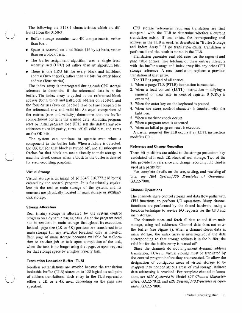
The following are 3158-1 characteristics which are different from the 3158-3:
• Buffer storage contains two 4K compartments, rather than four.
• Space is reserved on a halfblock (16-byte) basis, rather than on a block basis.
• The buffer assignment algorithm uses a single least recently used (LRU) bit rather than six algorithm bits.
• There is one LRU bit for every block and halfblock address (two entries), rather than six bits for every block address (four entries).
The index array is interrogated during each CPU storage reference to determine if the referenced data is in the buffer. The index array is cycled at th~~ referenced block address (both block and halfblock address on 3158-1 ), and the four entries (two on 3158-1) read out are compared to the referenced row and valid bit. An equal comparison of the entries (row and validity) determines that the buffer compartment contains the wanted data. An initial program reset or initial program load (IPL) sets the index array row addresses to valid parity, turns off all valid bits, and turns on the OK bits.
The system can continue to operate even when a component in the buffer fails. When a failure is detected, the OK bit for that block is turned off, and all subsequent fetches for that block are made directly to main storage. A machine check occurs when a block in the buff er is deleted for error-recording purposes.
Virtual Storage
Virtual storage is an image of 16 ,384K (16 ,777 ,216 bytes) created by the control program. It is functionally equivalent to the real or main storage of the system, and its contents are physically located in main storage or auxiliary disk storage.
Storage Allocation
Real (main) storage is allocated by the system control program on a dynamic paging basis. An entire program need not be resident in main storage throughout its execution. Instead, page size (2K or 4K) portions are transferred into main storage (in any available location) only as needed. Each page of main storage becomes available for reallocation to another job or task upon completion of the task, when the task is no longer using that page, or upon request for that storage space by a higher priority task.
Translation Lookaside Buffer {TLB)
Needless retranslations are avoided because the translation lookaside buffer (TLB) stores up to 128 logical-to-real pairs of address translations. Each entry in the TLB represents either a 2K or a 4K area, depending on the page size specified.
CPU storage references requmng translation are first compared with the TLB to determine whether a current translation exists. If one exists, the corresponding real address in the TLB is used, as described in "Buffer Storage and Index Array.'' If no translation exists, translation is performed and the result is stored in the TLB.
Translation generates real addresses for the segment and page table entries. The fetching of these entries interacts with the buffer storage and index array like any other CPU storage reference. A new translation replaces a previous translation at that entry.
The TLB is purged of all entries: 1. When a purge TLB (PTLB) instruction is executed. 2. When a load control (LCTL) instruction modifying a
segment or page size in control register 0 (CRO) is executed.
3. When the enter key on the keyboard is pressed. 4. When the store control character is touched with the
light pen. 5. When a machine check occurs. 6. When a program reset is executed. 7. When an initial program reset is executed.
A partial purge of the TLB occurs if an LCTL instruction modifies CR 1.
Reference and Change Recording
Three bit positions are added to the storage protection key associated with each 2K block of real storage. Two of the bits provide for reference and change recording; the third is used as a parity bit.
For complete details on the use, setting, and resetting of bits, see IBM System/ 370 Principles of Operation, GA22-7000.
Channel Operations
The channels share control storage and data flow paths with CPU functions, to perform 1/0 operations. Many channel functions are performed by the shared hardware, using a break-in technique to service I/O requests for the CPU and main storage.
The channels store and fetch all data to and from main storage, using real addresses. Channel data does not enter the buffer (see Figure 3). When a channel stores data in main storage, the index array is interrogated; if the data corresponding to that storage address is in the buffer, the valid bit for the buffer entry is turned off.
Since the channels do not implement dynamic address translation, CCWs in virtual storage must be translated by the control program before they are executed. To allow the designation of contiguous areas of virtual storage to be mapped into noncontiguous areas of real storage, indirect data addressing is provided. For complete channel information, see IBM System/370 Model 158 Channel Characteristics, GA22-7012, and IBM System/370 Principles of Operation, GA22-7000.
Central Processing Unit 11

I-fetch Buffers
4-byte Path
CPU
Channels
-------
-
Figure 3. Conceptual Data Flow in Model 158
Program Event Recording
Program event recording (PER) is a valuable program debugging aid. PER is enabled by turning on bit 1 of the EC mode program status word (PSW). Control registers 9-11 control the selection of registers and storage locations. For details concerning PER, see IBM System/ 370 Principles of Operation, GA22-7000.
Store Status Facility
The store status facility allows control information to be preserved and stored after a reset operation. The facility may be selected by touching . the light pen to the Store
12 S/370 Model 158 Functional Characteristics
High-speed Buffer Storage
8-byte Main Storage
BK Path 512K to 4,096K
{16 Bytes per Storage Cycle)
Index Array of Buffer Contents
4-byte Path
Status control character on the manual frame immediately following the reset function.
System Mask Changes
Two new instructions, store then AND system mask (STNSM) and store then OR system mask (STOSM), selectively enable or disable system mask bits in the PSW. The original value of the system mask is stored for later restoration. When the set system mask (SSM) instruction is executed and the SSM control bit (bit 1 of control register 0) is 1, a special operation exception is caused.
For a complete discussion of these changes, see IBM System/370 Principles of Operation, GA22-7000.
!~ ! )
l~l . J
If']

u
u
u
The system console of the Model 158 provides facilities for operating and controlling the system and for displaying system status. A small control panel, a keyboard, a cathode-ray tube (CRT) display, and a console disk file constitute the major operational components of the console. A console printer is available.
Most of the switches and pushbuttons normally associated with an operator's console are replaced by appropriate designations that are selectively displayed on the console screen. The entire system status cannot be displayed at one time; information is grouped logically into various frames (display categories), which are displayed on the CRT one at a time. Most of these frames are used as service aids by service personnel; only four (configuration, manual, program and alter/display) are used by the operator. Thus, advanced system maintenance and diagnostic procedures are combined with ease of operation to provide a high degree of efficiency.
The system console functions in one of two modes, depending on the operating system console support mode selected at initial microprogram load (IMPL) time. In systems providing device independent display operator console support (DIDOCS), the console can operate as a graphics display console with keyboard and selector (light) pen input and CRT output. The optional 3213 Printer provides hard-copy output. Alternatively, printer-keyboard mode may be selected with or without DIDOCS support, and the console then functions as a console I/O device similar to a 3215 Printer-Keyboard. When the console is operating in printer-keyboard mode, system-operator messages appear on the display screen but they can be displaced by subsequent messages before being acknowledged by the operator. The primary means of system communication in printer-keyboard mode are the 3213 Printer and the console keyboard.
The console file, located adjacent to the kneespace under the console keyboard, provides the microprograms required for the initial microprogram load (IMPL) of the reloadable control storage (RCS) of both the CPU and the console processor. A similar file, located in the rear of the console, is used for service and diagnostic purposes. Switches for the channel-to-channel adapter (CTCA) and for the integrated storage controls (ISC) are also located in the console file enclosure. An integrated data adapter for remote support of the Model 158 is standard on the console (see "Remote Support Facility" in the Introduction).
System Console
REMOTE SYSTEM CONSOLE
Another console, the IBM 3056 Remote System Console, is available as a special feature. It allows users to have operator control of a Model 158 from as much as 200 feet from the CPU. This enables users to have CPUs away from the center of activity, and thus permits more flexible organization of space for increased efficiency and convenience. For example, the 3056 can be located closer to the other system components which require attention. This console can be particularly worthwhile to users with multiple System/370s, enabling them to centralize operations.
The 3056, mounted on a standalone base, contains a CRT display and keyboard, identical to those on the main console. However, it has no light pen or printer. This console provides the operator with remote operational control over the system, including the ability to IPL, display the maintenance frames, and use the alter/display function. Controls not provided at the remote system console include those for system power on, IMPL, TOD clock, lamp test, and system power off.
The 3056 does not connect to a channel, but instead is a slave to the main console, and operates in parallel with it. The CRTs show the same displays, and responses can be made from either keyboard.
The remote system console has a disable key switch similar to that on the main console. When the main console key is locked and the remote system console key is unlocked, the remote operator has unrestricted access to all frames. When the remote system console key is locked, the remote operator has access only to the program frame, and is prohibited from performing an IPL or from altering programs or data. When the main console key is unlocked, the remote system console is inoperative.
CONSOLE SUPPORT
Device independent display operator console support (DIDOCS) for the CRT is the same as that provided for the IBM 3277 Display Station Model 2 supported by OS Release 21. This includes the selector pen (also referred to in this manual as the light pen), the keyboard, and the display area of twenty-four 80-character lines (the twentyfifth line is used by system functions and is independent of DIDOCS).
The 3213 Console Printer is supported as an output-only console under multiple console support (MCS) or its equivalent.
(The next page is intentionally blank) System Console 13

() /
()

f I v
Console support is provided under DIDOCS and MCS only when the display console is operating in display mode.
DISPLAY MODE CONSIDERATIONS
Basic to an understanding of console operation in display mode is an understanding of the cursor, the console buffer, and the definition of display data.
Cursor
The cursor is a positional indicator that assists the operator in entering data into the system accurately. Cursor positioning is controlled by keyboard operation, by light-pen operation of cursor controls (on the manual and alter/display frames), or by program control.
Console Buffer
The console buff er can store 2000 characters. Each buff er location corresponds to a similar screen location. (For example, buff er location 0 corresponds to display position 0.) Alphameric characters, certain special and control characters, and cursor information can be stored in any buffer location. If character codes other than those defined in bold outline in Table 1, Appendix A, are transferred to the buff er, the data characters displayed are not defined.
Data Fields
Console buffer storage, display, and logical manipulation of data are all field-oriented. A field is a group of consecutive alphameric characters starting with an attribute character and terminating with another attribute character which, in turn, defines the beginning of the next field. An attribute character is an eight-bit character that defines the characteristics of the data field that follows it. Programmed entry of
System Console 13.1

attribute characters establishes a formatted display. Figure 4 shows the characteristics indicated by the setting of the bits of the attribute character.
Provision is made for defining data as protected or unprotected; for tagging data as having been modified; for controlling the brightness of displayed fields regulating the use of the selector pen, and inhibiting display of data.
The attribute character is discussed under "Programmed Operations" (see "Display Mode").
CONTROL PANEL
The control panel of the System/370 Model 158 is shown in Figure 5. The CPU and service usage meters are located immediately beneath this panel.
Emergency Pull Switch
Pulling this switch turns off all power to the system proper (except for emergency power-off controls), and all control units and I/O devices connected to the I/O power-control interface. When pulled, the switch latches in the out position and disables the power-on pushbutton. The switch can be restored to its normal position by servicing personnel only.
Power-on Pushbutton
The power-on pushbutton is pressed to initiate the system power-on sequence. As part of this sequence, a power-on reset is performed. No instructions or 1/0 operations are executed until the system is explicitly directed to do so. After successful completion of the power-on sequence, the system enters the stopped state, the storage-protection array is cleared, and the TOD clock is cleared with its status forced to the not-set state.
The power-on pushbutton is backlighted red during the power-on sequence. If a power check condition exists, the pushbutton continues to be backlighted red. On successful completion of the power-on sequence, this. pushbutton is backlighted white. Following a successful power-on sequence, an initial microprogram load (IMPL) is automatically initiated.
During the power-on sequence, some noncritical circuits may be
7in an unstable condition and may be temporarily
activated. This does not affect the power-on sequence or the subsequent power-on reset.
Attribute Character Unprotected/ Bits X* 1 Protected
Bit Position 0 1 2
*Determined by the setting of bits 2, 4, 5, and 7.
Figure 4. Attribute Character Format
14 S/370 Model 158 Functional Characteristics
Not Used
3
TODCLK SECURE ENABLE SET
~ BDDEJ
REMOTE
CLOCK REMOTE CLOCK
POWER CHECK LOCAL
0
Figure 5. Control Panel, Systern/370 Model 158
Power-off Pushbutton
The power-off pushbutton is pressed to initiate the system power-off sequence. The contents of main storage are not preserved.
TOD Clock Switch
This spring-return lever switch provides an interlock against the inadvertent setting of the time-of-day clock. The set clock instruction is executed only while the switch is in the SET position.
IMPL Pushbutton
Pressing this pushbutton causes the initial microprogram loading of the system console and CPU reloadable control storage (RCS). During IMPL, the message 'IMPL IN PROCESS' is displayed on the CRT. At completion of the load, a system reset is automatically executed.
Intensity- Modified Selector Pen Not Data Detection Used Transfer
4 I 5 6 7
i~

Lamp Test Pushbutton
Pressing the lamp test pushbutton lights the power check and remote indicators, and the light emitting diodes (LED) on the console display bezel.
Remote/Local Clock Switch and Remote Clock Indicator
This switch and its associated indicator are used in a 315 8-3 multiprocessing system. Their operation and function are discussed under "System Control Panel Features."
Remote Pushbutton/Indicator
The remote pushbutton/indicator lights when the remote adapter is online. Pressing this pushbutton when the indicator light is on halts the teleprocessing function instantly (see "Remote Support Facility" in the Introduction).
Power Check Indicator
The power check light comes on to indicate that either a circuit breaker or thermal is tripped. During the power-on sequence, the power check light comes on to indicate that a voltage has failed to reach the required level. All cases require the attention of service personnel.
KEYBOARD
With the system console in display mode, the keyboard can duplicate most of the light pen (selector pen) functions. The exceptions are the selection of a program function key (PFK) entry (see "Program Frame") and resetting the flashing ALARM indication, both of which require lightpen selection. With the system console in printer-keyboard mode and the program frame displayed, the keyboard is the only means the operator can use to communicate with the system.
The three types of keys on the keyboard are: alphameric, cursor control (including backspace, forward and backward tabulate), and function.
Alphameric Keys
In conjunction with the shift keys, the 45 alphameric keys are capable of generating 63 EBCDIC codes. All keys have momentary action, with the exception of the keys with a
< 2
REQ
I
3 4 % 5
COPY SHIFT Z X C V
KEYBD RESET
Figure 6. Console Keyboard
> * 6 7 8
J
B N
( ) 9 0
0 p
K L ! $
M --,
T
- T
¢ @
II
? I
+
'T' in the top right corner (see Figure 6). These typamatic keys can be held down for repetitive use.
Typed characters appear on the CRT at the cursor location unless the console is operating in display mode and the cursor is in a protected field or in an attribute-character location. Keyed-in data is not effective until ENTER is pressed. This greatly reduces the possibility of entering erroneous or incorrectly formatted data.
Cursor Control Keys
Cursor control keys are differentiated as character-oriented keys that position the cursor in any character location and field-oriented keys that position the cursor at the first character location of a field.
The five character-oriented keys are backspace, cursor up, cursor down, cursor left, and cursor right. With the exception of the backspace key, which functions in both display mode and printer-keyboard mode, these keys are operative only in display mode or when alter/display is in use.
The three field-oriented keys are forward tabulate, backward tabulate, and new line. The effect of these keys on cursor movement depends on the operating mode and on the program definition of data fields.
Cursor Control Keys
Character Oriented Field on·ented
B Backspace B Forward Tabulate
[!] Cursor Up B Backward Tabulate
ITJ Cursor Down B New Line
B Cursor Left
G Cursor Right
Backspace: This key causes the cursor to move backward (to the left) one character position each time the key is pressed.
Cursor Up: Pressing this key causes the cursor to move up the screen in the same column. From the top of the screen, the cursor wraps to the bottom of the same column and continues upward again.
T
& - START STOP
MODE IRPT SEL
t T l T
T T SHIFT
ENTER
System Console 15

Cursor Down: Pressing. this key causes the cursor to move down the screen in the same column. From the bottom of the screen, the cursor wraps to the top of the screen in the same column and continues downward again.
Cursor Left: Pressing this key causes the cursor to scan one line at a time. From the top left comer of the screen, the cursor wraps to the bottom right corner of the screen and continues scanning.
Cursor Right: Pressing this key causes the cursor to scan to the right, progressing down the screen one line at a time. From the bottom right comer of the screen, the cursor wraps to the top left corner of the screen and continues scanning.
Forward Tabulate: With the console in display mode, the cursor spaces to the first character location of the next unprotected field. If the buff er is unformatted or if there are no unprotected fields, the cursor is repositioned to character location 0. When the console is in printer-keyboard mode, or when the alter/ display frame is in use, pressing this key generates a no-operation (NOP).
Backward Tabulate: Three sets of circumstances are recognized.
1. With the console in display mode, the cursor is located in either the attribute character or the first alphameric character of an unprotected field or in any character of a protected field. Action: The cursor moves to the first alphameric character of the first preceding unprotected field.
2. With the console in display mode, the cursor is located in any character of an unprotected field other than the first. Action: The cursor moves to the first character location of the field.
3. The buffer either contains no protected fields or is unformatted. Action: The cursor is positioned at character location 0.
When the console is in printer-keyboard mode, or when the alter/display frame is in use, pressing this key results in a no-operation.
New Line: With the console in display mode, cursor action is as follows:
1. (Formatted Buffer)-The cursor moves to the first unprotected character position in the first line down to have such an unprotected position. If there are no unprotected fields, the cursor moves to character location 0.
2. (Unformatted Buffer)-The cursor moves to the first position of the next line.
16 S/370 Model 158 Functional Characteristics
When the alter/display frame is in use, the current display is rolled up one line.
When the console is in printer-keyboard mode, the cursor moves to the first position of the next line.
Function Keys
Function keys are differentiated as those with modeindependent functions (i.e., those keys that function in the same manner each time they are used, regardless of whether the console is operating in display or printer-keyboard mode), and those with mode-dependent functions. In the first category are the start, stop, mode-select, interrupt, copy, lock, and shift keys; in the second category are the cancel, request, keyboard-reset, and enter keys. Modeindependent functions are described in the following text. Mode-dependent functions are illustrated in Figure 7.
Start: With the system in the manual (stopped) state, pressing the start key initiates CPU processing. The key is ineffective, however, if the system is in a hard-stop error condition.
Stop: Pressing the stop key places the system in the manual state.
Mode Select: If the mode select key is pressed while the program, alter/display, or configuration frame is displayed, the manual frame appears. If the mode select key is pressed while the manual frame is displayed, the program frame appears.
Interrupt: Pressing the interrupt (IRPT) key presents an external interruption to the CPU.
Copy: Pressing the copy key causes the displayed frame (with the exception of the program frame) to be copied on the console printer, if available.
Lock: Pressing the lock key locks the shift keys down. The shift lock is released when either of the two shift keys is pressed.
Shift: Pressing either of the two shift keys causes the upper character of those keys having two characters, or the' uppercase of single-character keys, to be effective.
CONSOLE DISPLAY
The console display is a cathode-ray tube unit with a minimum number of operator controls. The operator controls consist of manual intensity controls, a security key, and various bezel indicator lights (see Figure 8).

Key
Cancel
Request
Keyboard Reset
Enter
Display Mode
Presents an attention interruption to the channel. The attention identifier (AID) byte is set to CANCEL.
Generates a no-operation (NOP).
Resets an inhibit keyboard condition, attention identifier (AID) characters, and a pending attention interruption if the keyboard is not disabled because of an 1/0 operation in progress.
Presents an attention interruption to the channel. The attention identifier (AID) byte is set to ENTER.
Printer-Keyboard Mode
Presents a unit exception interruption to the channel if a read command is in process. Data in the buffer is transferred to main storage.
Presents an attention interruption to the channel.
Generates a no-operation (NOP).
Data keyed into the console buffer is transferred to main storage.
In the alter/display frame the function of these keys is as follows:
Cancel
Request
Keyboard Reset
Enter
Resets the alter/display frame to its initial state.
Generates a no-operation (NOP).
Causes an erase input function (nullifies all alterations displayed on the screen).
Causes data keyed into the console buffer to be transferred to main storage, and terminates function and facility specifications selected on the alter/display frame.
Figure 7. Mode-dependent Function Keys
Figure 8. Console Display
./ System Console 17

Intensity Controls
The intensity controls are on the left side of the bezel. The outer control varies the intensity of all displayed characters, both normal intensity and high intensity characters. The inner control varies the intensity of characters displayed in normal intensity fields; it has no effect on character fields programmed for high intensity display.
Security Key
The security key lock is on the side of the .console display. With the security key removed or in the vertical position, system data security is placed under control of system programming, and the operator is prevented from leaving the program frame. With the key positioned horizon tally, the mode select key is no longer suppressed.
Bezel Indicators
• Master Check-Turned on by any error in the system except integrated storage controls (ISC) IMPL checks.
• Console Check-Turned on by any error in the console.
If a console error occurs, console IMPL is automatically reinitiated and the message 'IMPL IN PROCESS' is displayed. The frame displayed at the completion of the IMPL depends on which frame was displayed at the time of the error. If the program frame was displayed, the frame reappears without any messages that may have been present prior to the console error. If any other frame was displayed, the service frame (with the console error indications) is displayed.
• ISCl IMPL Check-ISCl did not complete IMPL.
• ISC2 IMPL Check-ISC2 did not complete IMPL.
• Sequence Lights 3 and 4 on (1 and 2 off)-Console file diskette not mounted.
• Sequence Light 2 on (I, 3, and 4 off)-Console security switch not enabled.
All other sequence lights or combinations of sequence lights have no operational significance; they are used for diagnostic purposes.
Display Frames
Operation of the Model 158 requires an understanding of four frames on which the system configuration, operator manual controls, the alter/display function, and messages and system status are displayed. On the configuration, manual, and alter/display frames, either light pen (selector pen) or keyboard selection may be used. For example, the rate switch appears on the manual frame as:
• R-RATE •I-PROCESS • 2-I-STEP
18 S/370 Model 158 Functional Characteristics
Either process rate or instruction-step rate can be light-penselected simply by pressing the tip of the pen against the control character (lozenge) preceding the option. Keyboard selection is made by typing the letter R followed by 1 or 2, depending on the option required. An arrow indicates the current selection.
Cursor controls are provided on frames where positioning of data being entered into the console buff er is required. These controls are discussed in the description of each frame when appropriate.
Configuration Frame
At the completion of initial microprogram load (IMPL), which is normally initiated by the power-on sequence, the configuration frame automatically appears (see Figure 9). Installed features, channel configuration, and a list of shared unit control words (UCW) are among the items displayed on this frame. If printer-keyboard mode of operation is required, it must be selected, since the power-on sequence takes place in display mode. Timer options are also selected on the configuration frame.
Exit from this frame is made either by light pen selection of the 'manual' control character or by pressing the mode select key on the keyboard. The manual frame then appears.
Selecting 'service' will display the service frame, which is not required for normal operation. Sel,ecting 'copy' results in a facsimile of the configuration frame being printed on the console printer, if the console printer is available.
Manual Frame
The manual frame (Figure 10) displays the current state of the Model 158 and provides a means of initiating operator functions, using either the light pen (selector pen) or the keyboard.
Other frames are selected from the manual frame. In normal operation, the operator will have occasion to request the program frame so that output messages can be received or the alter/display frame to examine the registers. Selection of the alter/display frame, for instance, is made by pressing the light pen against the control character preceding the selection or by entering the characters 'F3' from the key board.
Operator functions that can be selected by light pen or keyboard action are: 01-PSW Restart (Prgm) 02-Restart (Prgm) 03-System Reset 04-Load 05-Store Status 06-Sys Reset (Clear) 07-Load (Clear)

u
u
CPU FEATURES MXX 707X DOS EMUL EXT PREC
DIRECT CTL MP
CONSOLE DEVICES DISPLAY=OXX 3213 =OXX PRT/KBD=OXX REMOTE =OXX
LANGUAGE GROUP USA
•MANUAL •SERVICE
-CONFIGURATION-SELECTED FEATURES CHANNELS
DISABLED ADAPTERS CTCA ISCJ., ISC2
•COPY
CHAN 0 !MPX) CHAN 1 ( BMPX) CHAN 2 ( BMPX J CHAN 3 (BMPXl CHAN 4 (MPX OR BMPXl CHAN 5 (BMPX)
STORAGE X.X MEG
l.J•-SHARED UCWS 000+08X+007+0FX 400+48X+407+4FX CCX CCX CCX CCX CCX CCX CCX CCX CCX CCX CCX CCX CCX CCX CCX CCX CCX CCX CCX CCX CCX CCX CCX CCX CCX CCX CCX CCX CCX CCX CCX CCX CCX CCX CCX CCX CCX CCX CCX CCX
PSW-XXXXXXXX XXXXXXXX
M-CONSOLE MODES +•1-DISPLAY
•2-PRINTER KBD
D~DISABLE
•1-T IMER EXCPN •2-INTV TIMER •3-CONSOLE •4-POWER WARNING •5-3213 •6-REMOTE CONSOLE
F-SELECTABLE FEATURE
•1-FEATURE VERIFY
MAN WAIT TEST
Figure 9. Configuration Frame (3158-3 shown; 3158-1 differs slightly)
S-SAR COMP SEL( REAU C-CHK CNTL F-FRAME CONTROL •1-ANY •5-STOP -+•1-PROCESS •:L-PROGRAM FRAME •2-STORE •2-HARD STOP •2-SERVICE FRAME •3-FETCH •3-ALTER/DISPLAY •4-I/O •4-CONFIGURATION CURSOR
CONTROLS E-SAR COMP Sl:T (REAL) I-SET IC
•000000 •000000
G-ADR COMP SEU LOGL) R-RATE 0-0PERATOR FUNCTIONS •FWD •:L-STORE -+•:L-PROCESS •:L-PSW RESTART(PRGMl •BKWD •2-IAR •2-I-STEP •2-RESTARTIPRGMl
•3-SYSHM RESET HEX H-ADR COMP Sl:T(LOGLl •4-LOAD INPUT
•:L-ADR:L 0.000000 •5-STORE STATUS •2-DATA c.oo •6-SYS RESET(CLEARl 0 :L
•7-LOAD (CLEAR l 2 3 •3-ADR2 0.000000 4 5 •4-DATA c.00000000 L-LOAD UA W-SWAP 6 7
•OOO •SAR :L3 8 9 •5-ADR3 0.000000 A B •6-DATA c.00000000 X-EXECUTE c D
•OPERATOR FUNCTION E F
HDW=:LXXX •ENTER •COPY PSW=XXXXXXXX XXXXXXXX SYS MAN WAIT TEST
Figure 10. Manual Frame
After the operator selects the desired function, having previously entered the load unit address for load or load (clear), the execute (X) operator function must be invoked, either by typing 'X' or by pressing the light pen to the control character.
using the new PSW. If the system is stopped but not hardstopped, it enters the running state. The program frame is automatically displayed.
01-PSW Restart (Prgm): Selecting PSW RESTART (PRGM) causes a system reset followed by loading of a new PSW from location 0. If instruction-step rate is in use, the manual loop is entered prior to executing the first instruction. If process rate is in use, processing resumes with the new PSW, and the program frame is displayed.
02-Restart (Prgm): When RESTART (PRGM) is activated, the current instruction is completed if the system is running. The updated PSW is stored in location 8. A new PSW is loaded from location 0, and processing continues,
03-System Reset: Initiation of SYSTEM RESET causes the CPU clocks to stop in order to permit all pending storage operations to be completed. Then all machine logic is reset. A branch to the reset microprogram is forced, all channel operations are terminated, and a reset is signaled to all control units. All registers, buffers, the index array, and local storage become validated.
04-Load: When LOAD is selected, followed by L-LOAD UA, a cursor appears under the first digit position of load unit address. The light pen can then be used to select a hex digit from the hex input matrix, or the keyboard can be used. The selected digit appears in the first position of the
System Console 19

load unit address, and the cursor advances to the next position. This process continues until the initial program load (IPL) device address has been entered. Upon successful completion of IPL, the program frame appears automatically. If the IPL is unsuccessful, the manual frame remains.
05-Store Status: The selection of STORE STATUS immediately following the reset function allows control information to be preserved and stored.
06-System Reset {Clear): SYS RESET (CLEAR) initiates the same action as RESET but, in addition, main storage and storage protection arrays are cleared to zeros with good parity.
07-Load {Clear): LOAD (CLEAR) initiates the same action as LOAD but, in addition, the IPL is preceded by an initial program reset and the clearing of main storage and storage protection arrays.
W-Swap SAR 13: SWAP SAR 13, when selected, causes bit 13 of the storage address register (SAR) to be inverted. This results in changing the physical location of storage addresses, and the function can be used to load programs even though storage errors may exist. This function, when selected, is not activated until a load (clear) or system reset (clear) is performed.
The SAR compare select and address compare select functions are used to stop the system when certain predetermined conditions are met.
Bits 29-31 of the SAR are ignored for CPU and 1/0 data transfers of less than four words. Bit 28 is also ignored in printer-keyboard mode on four-word data transfers. The logic does not distinguish between main storage and storage protection array transfers.
S-SAR Compare Select {Real): Selection of one of these functions causes the address in the storage address register (SAR) to be compared with the address in the compare register, the address of which is set by E-SAR COMP SET (REAL). If a match occurs and the selected condition is met, the CPU will either stop or send out a sync pulse, depending on the setting of the.stop function, SS. The SAR compare select functions are described in the following text.
Sl-ANY
S2-STORE
S3-FETCH
Causes the action when SAR matches the compare register (real addresses). Causes the action when the SAR matches the compare register and a store operation is being performed (real addresses). Causes the action when the SAR matches the compare register and a fetch operation is being performed (real addresses).
20 S/370 Model 158 Functional Characteristics
S4-I/O Causes the action if the SAR matches the compare register (real addresses) and the console is operating in printer-keyboard mode.
E-SAR Compare Set {Real): The SAR compare parameter is changed by selecting the control character to the left of the address field. The new address appears left-justified as it is entered from either the hex input matrix or the keyboard. The operation is completed by selecting the enter control character or the enter key on the keyboard.
G-Address Compare Select {Logical): When either G 1-STORE or G2-IAR (instruction address register) is selected, the stopping hardware is activated by the ADR COMP SEL and ADR COMP SET parameters (G and H). The cursor indicates the selected facility. (Note: Selection of G 1 or G2 degrades system performance.)
H-Address Compare Set {Logical): The address compare parameter is changed by selecting the control character to the left of the desired field or by typing the required letter and number combination (e.g., Hl). The cursor then appears to the right of the decimal on the selected line. Up to three address bytes may now be entered. Backspacing the cursor over the decimal allows a base register value to be entered. When 'enter' is activated, the address is right-justified.
Selection of the H2 parameter positions the cursor to the right of the decimal on the data line. The state of the data parameter may be set by backspacing the cursor over the decimal and entering one of the following:
C (default) 1 0
Stop condition* on an equal compare. Stop condition* if selected bits= 1. Stop condition* if selected bits= 0.
*Stop condition means that, if the corresponding condition is true, a stop may occur, subject to the remaining stop conditions being true.
When an JAR or STORE compare occurs at the effective address specified by ADR 1, a comparison based on the first data parameter takes place. If the H3, H4, or HS, H6 parameters have also been activated, a similar comparison takes place based on the second data parameter, followed by the third data parameter. When all conditions are met, a stop occurs unless the stop has been purged by other diagnostic aids.
Messages explaining the data parameters are displayed whenever the H2, H4, or H6 control character is selected for input.
C-Check Control: Either PROCESS or HARD STOP mode may be selected. In process mode, normal operation is in effect with all error and retry functions enabled. In hard stop mode, the CPU clocks will be stopped by any error
(~
n /

I '. u
that causes a machine-check trap. The logout and instruction retry are not taken until the clocks are restarted by activating start clocks on the service frame (a maintenance function).
I-Set Instruction Counter: The instruction counter can be set to any desired value by selecting the control character to the left of the address field and entering data in a manner similar to that described for SAR COMPARE SET.
R-Rate: The rate switch can be set either to process or to instruction step. The selection made is indicated by an arrow. The start key on the keyboard is used to initiate execution of the next instruction when instruction-step rate is in effect.
System Status Indicators
The system status indicators are displayed on the manual frame to indicate system status as defined in the following text.
System: SYS is displayed when the CPU or service meter is running; the space is blank when the meters are stopped.
Manual: MAN is displayed when the CPU is in the stopped state; the space is blank when the system is running.
Wait: WAIT is displayed when the CPU is in the wait state (bit 14 in the current PSW isl); the space is blank when the bit is 0.
Test: TEST is displayed when any manual control is not in its normal position; the space is blank when all controls are at normal setting.
PSW: The PSW is also displayed on the manual frame. Its meaning will depend on whether the system is operating in extended control (EC) or basic control (BC) mode of operation. (Note: The program mask bits are not defined in either mode of operation.)
For complete PSW status information, see IBM System/370 Principles of Operation, GA22-7000.
Program Frame
The program frame serves as the output device for the control program and other programs operating in the Model 158; it is selected automatically upon successful completion
of IPL. The program frame can also be manually selected from the manual and service frames. The image is cleared or initialized by any of the following operator functions:
System Reset System Reset (Clear) Load Load (Clear) PSW Restart.
The screen format varies according to the mode of console operation selected. When the system console is operating in printer-keyboard mode, twenty-four 80-character lines are available for system-operator messages. The twenty-fifth line is used to display the system indicators and the PSW (see Figure 11). When the system console is operating in display mode (with DIDOCS support, the screen is divided into five functional areas (Figure 12)).
1
1
2 3
•
Message Area (19 lines)
• I 17 18 19 20 PFK Display Line 21 Instruction Line 22 Entry Area 23 (2 lines) 24 Warning Line 25 System Indicators
Figure 12. Program Frame Format (Display Mode)
Message Area-Lines 1 through 19: The message area is used for system messages, operator commands, and status displays. Each line contains 78 visible character positions. (The two positions preceding the first visible character position are used as system indicators and are not displayed.) The first two visible positions are used for the message number if message numbering is in effect. Positions 3, 4, and 5 contain characters that define the type of the status of the message that follows (see "Message Status Indicators"). The message text is contained in positions 6 through 78, and, if necessary, is continued on the next line beginning at position 6.
PROCEED REQUEST ALARM 3213 INTVN REQD PSW=XXXXXXXX XXXXXXXX SYS MAN WAIT TEST
Figure 11. Program Frame Line 25 (Printer-Keyboard Mode)
System Console 21

Program Function Key (PFK) Display Line-Line 20: This line is blank when selector (light) pen command entry is not in use. When requested, a display with the following format appears in the PFK display line: 1 2 3 4 5 6 7 8 9 10 11 12 Only those numbers that were designated for PFK command entry functions at the time of system generation appear in the display.
Instruction Line-Line 21: This line is used for certain system messages relating to console control. Messages appearing in this line are displayed at higher intensity than other messages on the screen.
Entry Area-Lines 22 and 23: The operator uses these two lines in conjunction with the cursor and keyboard to enter commands to the system.
Warning Line-Line 24: This line contains warning messages normally requiring operator action. These messages are also displayed at high intensity.
System Indicators Line-Line 25: This line, which is not supported by DIDOCS, is used to display system indicators (see Figure 13). Selection of any position on line 25 with the light pen also serves to reset the console alarm.
Message Status Indicators: These special indicators appear in positions 3, 4, and 5 of the lines in the message area.
• A vertical line (I) in position three indicates that required action has been taken for the message or that the message can be deleted.
• A horizontal bar ( - ) in position 3 indicates that the message is informative and requires no operator action.
OD An asterisk(*) in position 4 indicates that the message is a system message that requires action by the operator.
• A commercial at sign (@) in position 4 indicates that the message is a problem program message that requires operator action.
• A plus sign ( +) in position 5 indicates that the message is a problem program WTO (Write To Operator) Message.
More detailed information on the program frame can be found in OS/VS2 Display Consoles, GC38-0260.
Alter/Display Frame
The alter/display frame (Figure 14) can be entered only from the manual frame when the clocks are running and the
or
CPU is in the stopped (manual) state. The alter/display frame allows the operator to display and/or alter the following facilities within the CPU:
1) M Real Main Storage 2) V - Virtual Main Storage 3) K Main Storage Storage Protection Keys 4) E Real Channel UCWs 5) U - Logical Channel UCWs 6) T Active UCW s 7) L CPU Local Storage 8) I 1/0 UCW Local Store 9) B 1/0 Buffer Local Storage
10) C Control Registers 11) G General Purpose Registers 12) F Floating-point Registers 13) P PSW 14) X Prefix Register
The operator has the option of either keying in the function, facility, and address desired oir using the light pen.
Keyboard Selection: The operator enters the function code 'A' for alter or 'D' for display. The sounding of the audible alarm and the failure of the cursor to move from the reset position (under 'K' in KEY IN/ADDRESS) indicates that an invalid function code has been entered. A valid function code must be entered before the cursor will reposition one position to the right. Next, the operator enters the facility code required. Again, if the code is invalid, the audible alarm sounds, and the cursor does not advance. When a valid code is entered, the cursor advances to the leftmost digit position. in the address field. The reset value of this field is defined as 000000. If an address is required, it can be keyed in; it will be displayed left-justified as keyed. All address characters are checked for a hex value of 0 through F. Invalid characters are ignored, and the console alarm sounds.
Light Pen Selection: The operator first selects the function and then the facility desired by pressing the light pen to the appropriate control character. The cursor appears in the address field. If an address is required, it is selected from the hex input matrix at the lower right corner of the frame by pressing the pen to the required digits in turn. As each digit is selected, it appears at the cursor position in the address field.
Display: After selection is completed, the data is displayed at the center of the screen together with the address of the first element of each line if applicable. Invalid addresses are
(SYSTEM AVAILABLE
INPUT INHIBITED PSW=XXXXXXXX XXXXXXXX SYS MAN WAIT TEST
Figure 13. Program Frame Line 25 (Display Mode)
22 S/370 Model 158 Functional Characteristics
(~ I )
/~ )

FUN CT ION •A-ENABLE ALTER
64th Character
•D-DISPLAY XXXXXX=XXXXXXXX XXXXXXXX XXXXXXXX XXXXXXXX FACILITY
•M-MAIN STOR REAL X •V-MAIN STOR VIRT •K-MAIN STOR KEYS X •E-UCW REAL •U-UCW LOGICAL X •T-UCW ACTIVE •L-CPU LOCAL X •I-I/0 LOCAL •B-I/O BUFFER X •C-CTRL REGS •G-GENERAL REGS X •F-FLT PT REGS •P-PSW X •X-PREFIX REG
KEY IN/ADDRESS X xx •000000
FRAME CONTROL X •NEW LINE •ERASE INPUT
CURSOR CONTROLS
•UP •DOWN •FWD •BKWD
HEX INPUT
0 l 2 3 4 5 6 7 8 9 A B C D E F
•MANUAL •SERVICE •ENTER •COPY PSW=XXXXXXXX XXXXXXXX SYS MAN WAIT TEST
Figure 14. Alter/Display Frame
flagged in the display area by the characters '=IV A' following the invalid address
The amount of data displayed depends on the facility selected. Data is displayed on alternate lines, that is, the third, fifth, seventh, and so on. If the 'alter' function is selected, the cursor is located on the blank line under the element having the address specified at facility selection time. If 'display' was selected and the alter function is desired, 'enable alter' can now be selected, and the desired alterations can be made. Once alterations are made, 'enter' must be selected in order to store the altered data.
Should the display of more data be required, touching the light pen to the 'new line' control character (or entering special character NL (X'l5') on the keyboard) shifts the data displayed on the screen up two lines, and a new line with address information appears at the bottom of the screen. If the cursor was on any line other than the top line, it maintains its relative position. If, however, it was on the top line, it will now be positioned under the first element of the new top line.
Note that, if data on the top line of the display area is to be altered, either the control character for 'enter' or the enter key must be pressed in order to store the data as altered before selecting the 'new line' functon; otherwise the data will remain unaltered.
Cursor Controls: Cursor controls are provided at the right side of the screen for light pen (selector pen) operation. For a keying opera ti on, the space bar, the backspace key, and the cursor control keys on the right side of the keyboard can be used.
The cursor appears only on the blank lines, so that a display of the original data can be maintained as well as the changes made to it. As the data is entered, the digit appears at the cursor position under the old value, and the cursor advances. Keyed-in data is checked for a hex value of 0
through F. Invalid characters are not displayed, the cursor does not advance, and the console alarm sounds.
Enter: In order to store altered data, the enter function must be selected either from the keyboard or by use of the light pen. When this function is selected, the address appears right-justified in the address field, and the keyed-in data is transferred to main storage. The selected function and facility specifications on the frame are terminated.
Note that the enter function must be selected prior to the new line function in order to store altered data appearing on the top line of the display area.
Erase Input: Selecting this option nullifies all alterations displayed on the screen. The function, facility, and original data remain unchanged.
Copy: Copy must be selected if a printed copy of the display is desired. Pressing the copy key or selecting the copy function with the light pen is the only operation required.
HIERARCHICAL MONITORING SYSTEM
The hierarchical monitoring system (HMS) is a service aid provided by the System/370 3158-3 service processor to assist in diagnosing microcode and programming problems. The HMS is supported by an HMS frame on the console display, and all HMS controls and execution results are contained within this frame.
The HMS is capable of monitoring two facets of any program: (1) the execution of any instruction in the instruction stream and (2) the alteration of any storage content. Monitoring is done by stopping the normal execution at either of the two points listed above, at which time a number of the system facilities, such as GPRs, control registers, and PSWs (status indicators) can be fetched by the HMS for testing, displaying, or storing.
System Console 23

The monitoring system is capable of checking system indicator status information concurrent with execution of particular reloadable control store (RCS) control words. The microcode hierarchy of monitoring and the program hierarchy of monitoring can be mixed in any HMS monitoring program.
The HMS has the capability of solving significant system problems while the CPU operates normally. With or without an operating system, the HMS can monitor RCS and the application program concurrently in either a real or a virtual environment.
For a detailed account of HMS operation and programming, see IBM System/370 Model 158 Hierarchical Monitoring System, Feature Description, GA22-7056.
IBM 3213 CONSOLE PRINTER
The IBM 3213 Console Printer is a table-top printer that provides printed output for the Model 158 (see Figure 15). Characters are printed as a pattern of dots formed by a vertical row of seven wires striking the ribbon and paper as the print head moves along the print line. Under program control, printing can occur at a rate of up to 85 characters per second. Character spacing is 10 per inch (25,4 mm) and up to 126 per line. Line spacing is either six lines per inch or three lines per inch depending on the setting of the line-feed select lever.
All printer-keyboard commands are recognized by the 3213 in printer-keyboard mode. In display mode, READ (OA) is not recognized (see "Printer-Keyboard Mode" under "Programmed Operations").
Figure 15. IBM 3213 Console Printer
24 S/370 Model 158 Functional Characteristics
All printing, carrier operations, and forms movement controls are initiated in the system. An end-of-forms switch signals the system that the end-of-form is within 4-~ inches (107,9 mm).
Printer Controls and Indicators
External controls and indicators on the 3213 Console Printer consist of a power-on/off switch, an end-of-forms indicator, and an attention indicator.
End-of-Forms: This light comes on to indicate that an end-of-forms condition is imminent or that a cover interlock is open.
Attention: This light comes on when the power-on/off switch is off; if power is on, a missing or incorrect voltage level that requires the attention of service personnel is indicated.
Operator Controls
Paper-advance Knobs: Rotating the knob on either end of the platen moves the form for coarse vertical positioning.
Vertical Alignment Vernier: Pressing in and rotating the paper-advance knob on the right end of the platen provides fine vertical adjustment of the form to the print line.
Line-/ eed Select Lever: The line-feed select lever allows the operator to select either single ( 6 lines per inch) or double (3 lines per inch) spacing.
Copy-control Lever: The copy-control lever adjusts the clearance between the platen and the print head to accommodate the thickness of the forms used. Five positions of the lever allow for a maximum form thickness of 0.018 inch (0,46 mm).
Forms Specifications
The 3213 accepts marginally punched, continuous-form paper. Forms can be from one to six parts depending on the weight of paper and carbon used. However, for optimum feeding and stacking, forms of no more than three parts are recommended. Form width must conform to the pin-feed platen installed (see Figure 16). Form length can be from 3 to 14 inches (76,2 to 355 ,6 mm). For optimum stacking, 11 inches (279 ,4 mm) is recommended. The special ribbon cartridge has a ribbon life of at least two million characters.
Overall Width Hole-to-Hole Width Print Positions
Inches Millimeters Inches Millimeters Maximum
13 330,2 12-1 /2 317 ,5 120
13-5/8 346,1 13-1 /8 333,4 126
Figure 16. Available Pin-feed Platens, IBM 3213 Console Printer
)

u
I I Ii '\_)
The following text provides programming information for both display and printer-keyboard modes of operation. Basic to both modes of operation are the concepts of protected or unprotected data and the modified data transfer function.
Protected Data-Auto Lock: A program-controlled feature of the console allows fields to be defined as protected or unprotected. A protected field is a field that the operator may not alter in any way. If an attempt is made to enter an alphameric character when the cursor is located in a protected field, the keyboard becomes disabled by the auto lock function.
An unprotected field is one in which the operator can enter, modify, and erase alphameric data from the keyboard.
Modified Data Transfer: When it is necessary to identify data fields that have been modified, the modified data transter (MDT) bit (bit 7 of the attribute character) is set to 1. The process is referred to as "tagging" the field.
Data in protected or unprotected fields can be tagged as having been modified. In protected fields, the tags are set under program control or by means of the light (selector) pen. In unprotected fields, modified data tags are also set by keyboard operation. These tagged fields are the only fields transferred upon execution of a read modified command.
DISPLAY MODE
In display mode, the system console from the standpoint of the operating system, performs as an IBM 3277 Model 2 Display Station with keyboard. A subset of the 3277 commands and orders is used as described in the following text.
Control Characters
Programmed control characters are the attention identifier (AID), write control character (WCC), and attribute characters.
Attention Identifier (AID)
An AID character is set in the console when one of the following events occurs: 1. The enter key is pressed (AID = 7D). 2. The cancel key is pressed (AID = 6E). 3. The selector (light) pen detects a character in a
selector-pen-detectable field (AID= 7E).
Programmed Operations
The AID character causes an I/O pending condition to be set in the console, and attention status is presented to the channel. Normal program response to attention status is to issue a read modified command. The first character transferred on this command is the AID character, which identifies the cause of the attention status generation. The AID character is reset when one of the following events occurs: 1. Keyboard reset is pressed. 2. A write command is issued with the WCC keyboard reset
bit set to 1. 3. An erase all unprotected command is executed.
Write Control Character (WCC)
The WCC is used in conjunction with both the write command and the erase write command to specify certain device operations. The wee is identified by its position as the first character in a write or erase write command data stream. If an operation that does not apply to the console is specified in the wee, the operation is ignored; no status or sense information is generated.
Bit usage in the write control character is defined in Figure 17.
Attribute Characters
Attribute characters describe the characteristics of the data fields that follow them. A formatted display is established by programmed entry of attribute characters, which are interpreted in display mode by the bit settings (refer to Figure 18).
The MDT bit in the attribute character is an exception to the general rule that an attribute character is protected from modification by keyboard action. MDT bits can be set under program control, via keyboard entry, or via selector pen detection.
Under program control, the start field order sequence in a write or erase write command data stream is used to enter an attribute character in the CRT buffer. Since the MDT bit is part of the attribute character, it can be defined as set or reset by the program. The erase all unprotected command resets the MDT bits in all unprotected fields. The reset MDT bit (bit 7) in the write control character (WCC) of a write or erase write command permits resetting of all MDT bits under program control.
Selector Pen Detection
The setting of bits in the attribute character controls the use of the selector (light) pen. A field in which selector pen
Programmed Operations 25

Write Control Character Bit Not Not Not Sound Restore Reset Assignment x 1 Used Used Used Alarm Keyboard MDT Bits
0 1 2 3 4 5 6 7
Bit 0 Determined by the setting of bits 5, 6, and 7.
Bit 1 Always= 1.
Bits 2, 3, and 4 Ignored.
Bit 5 = 1 Sounds audible alarm .
Bit 6 1 Restores the keyboard and resets the attention identifier (AID) byte upon termination of the 1/0 command.
Bit 7 = 1 Resets all modified data transfer (MDT) bits to 0. (The MDT bits are reset prior to the write operations so that specified modified data transfer bits can be set to 1 by the write data stream.)
Figure 17. Write Control Character (WCC) Bit Usage
Attribute Intensity- Modified Character x 1
Unprotected/ Not Selector Pen Not Data Bits Protected Used Detection Used Transfer
Bit Position 0 1 2 3 4 I ~ "' 7
0 Determined by the setting of bits 2, 4, 5, and 7
1 Always= 1
2=0 Data is unprotected = 1 Data is protected
3 Not used
4,5 0,0 Normal intensity field - nondetectable = 0, 1 Normal intensity field - selector-pen-detectable = 1, 0 High intensity field selector-pen-detectable = 1, 1 Nondisplay field - nondetectable
6 Not used
7 0 Field data not tagged as having been modified 1 Field data tagged as having been modified
Note: Bits 0 and 1 are not decoded by the console. They are transferred as received.
Figure 18. Attribute Character Bit Usage
26 S/370 Model 158 Functional Characteristics

u
u
u
detection is possible, and in which the consequent proper setting of the modified data transfer (MDT) bit is assured, may be protected or unprotected.
A field is selector-pen-detectable if: 1. Bits 4 and 5 of the attribute character are set to 0 and 1
(normal intensity/ selector pen detectable), or 1 and 0 (high intensity /selector pen detectable), and
2. The designator (the character immediately following the attribute character) is a question mark (?), a 'greater than' symbol(>), or a blank (X'40').
If any character in a selector-pen-detectable (SPD) field is sensed by the pen, a detection is said to have occurred.
Designator
If the designator in a detected field is a question mark (?), it is changed to a 'greater than' sign (> ), and the MDT bit is set to 1.
If the designator in a detected field is a 'greater than' sign (>), it is changed to a question mark(?), and the MDT bit is reset to 0.
If the designator is a blank, no change is made, the MDT bit is set to 1, and I/O pending is generated.
I /0 Operation
As a result of a selector pen. detection in a field containing either a ? or a blank designator, the MDT bit is set to 1, and the field (protected or unprotected) is read back during a read modified operation. A single selector pen detection in a field with a > designator, or a double detection on the same designator character location (resulting in a two-fold change, [? to>] and [>to ?]) resets the associated MDT bit to 0 and prevents that field from being read back during a read modified operation.
Note: A similar operation from the keyboard (changing the alphameric value of a character, thereby causing the MDT bit to be set to 1 , and then changing the character back to its original value) does not reset the MDT bit to 0.
Console Commands
In display mode, the console accepts the following commands: Test I/O (TIO) Write Read Buffer No-operation Select Sense Erase Write Read Modified Erase All
(00) (01) (02) (03) }(Both of these commands are (OB) treated as no-operations (NOP)). (04) (05) (06)
Unprotected (07) All other commands are rejected.
Note: In the following description of the write, erase write, and read buff er commands, reference is made to order sequences. A complete description of order sequences can be found following the discussion of console commands.
Test I /0 (00)
The TIO command can be used to determine pending status or to test for device busy. No interruptions are generated.
Write (01)
A minimum data stream of one character, the write control character (WCC) must follow a write command. The starting buffer address for data transfers depends on the following: 1. If a WCC is followed by a set buffer address (SBA) order
sequence in the write data stream, data character entry begins at the buffer address specified by the SBA order sequence.
2. If a write control character (WCC) is followed by other than an SBA order sequence, the buffer location at which data entry begins is a function of command chaining. a. If the write command is unchained, or chained from
a select, no-op or sense command, data character entry begins at the buffer address containing the cursor.
b. If the write command is chained from a write, erase write, erase all unprotected, read modified, or read buffer command, data character entry begins at the current buffer address.
If a write command is the first command in a chain and the data stream contains only the wee, the command resets the buffer address to the current cursor location. The buffer address is advanced one location with each character stored. Data character storage in successive buffer locations continues until an order sequence that alters the buffer address is encountered in the data stream, or until the write command data stream is terminated.
The location of the cursor is not affected by the write command unless an insert cursor order sequence is included in the data stream.
The write command is ended when the last character in the write data stream is received. Following receipt of the last character in the write data stream, the operations specified in the wee are executed, with the exception of the 'reset modified data tag bit' operation, which is executed prior to the receipt of the write data stream.
Read Buffer (02)
The read buffer data stream consists of the three-character read heading (AID, CUR ADR, CUR ADR) followed by the contents of all buffer locations (protected and unprotected,
Programmed Operations 27

attributes and nulls). The transfer starts at a specific location and continues to the end of the buffer. The beginning of each field is identified in the read-buffer data stream by a start field (SF) order code (hex 'lD') followed by the attribute character associated with that field. The starting address for data transfer is a function of command chaining as follows: 1. If the read buffer command is unchained, or if it is
chained from a select, no-op, test 1/0, or sense command, the transfer begins at buffer location 0.
2. If the read buffer command is chained from a write, erase write, erase all unprotected, read modified, or read buffer command, transfer begins at the current buffer address.
Transfer continues until the last buffer location (1919) is reached, unless the channel count goes to 0. A typical read buffer data stream is: AID, CUR ADR, CUR ADR, SF, ATRl, DATA, ... , SF, ATR2, DATA ... , SF, ATR3, DATA ...... etc.
No-operation/Select (03/08)
No-operation and select are both treated as a no-operation. Although they perform no functional operation, they may be used as a programmed switch in a command chain. Channel end and device end will be presented at initial status time unless a pending status condition or a busy condition exists.
Sense (04)
The sense command transfers one byte of sense data to the CPU in response to unit check status. The meaning of each bit is defined under "Sense Byte."
Erase Write (05)
The erase write command clears the entire storage buffer to nulls (hex '00'), stores any new data characters provided by the program, and performs those operations specified by the write control character (WCC). A minimum data stream of one character' the wee, must follow the erase write command.
Following receipt of the erase write command: 1. Every character location in the buffer is set to a null
(hex '00'). 2. The buffer address is reset to 0. 3. The cursor is positioned at buffer location 0. Data is stored in the buffer according to the contents of the erase write data stream. The WCC and all order sequences are executed in the same manner as in the write command. Order sequence operations are based on initial buff er conditions of (1) buffer address = 0, or (2). buffer is unformatted.
Operation: After accepting the erase write command, the console erases buffer location 0 to a null and inserts a
28 S/370 Model 158 Functional Characteristics
cursor in that position. The console then proceeds to erase the remaining locations in the buff er to nulls, concluding the opera ti on at location 1919. The next operation is set to start at buffer address 0. Following the erasure, the console accepts and stores the WCC. The erase write command then proceeds as a normal write command. A 'reset MDT' WCC action request is ignored on an erase write operation, since the erase operation resets all modified data transfer bits.
Read Modified (06)
When a standard read modified command is performed, all fields (protected and unprotected) in which the modified data transfer (MDT) bit has been set are read for transfer to the CPU. A three-character read heading consisting of the AID code followed by the two-character buff er address of the cursor precedes the read modified data stream. Following the read heading, the read modified data stream contains the alphameric data from each field in which the MDT bit is set, preceded by a set buffer address (SBA) order code _and the two-character position in the tagged field (attribute+ 1). Null characters contained in the tagged fields are suppressed; they are not included in the read modified data stream.
The buffer location at which the search begins for the first attribute character defining a field that contains modified data depends on the following considerations: 1. If the read modified command is unchained or if it is
chained from a select, no-op, test 1/0, or sense command, the search begins at buffer location 0.
2. If the read modified command is chained from a write, erase write, erase all unprotected, read buffer, or read modified command, the search begins at the current buffer address.
The search for modified data fields ends at the last character location (1919) in the buffer. If a modified field continues beyond the last character location and wraps around to the first, the transfer of modified data associated with that field continues to the end of the field. Any time a modified field is wrapped, it is the last field transferred, and the buffer address is set to the attribute character location of the next field. In all other cases of a normally terminating read modified operation, the buffer address is set to character address 0.
If the buffer is formatted but no fields contain modified data, only the three-character heading data is transferred. If the buffer is formatted, transfer, starting at location 0, includes the three-character heading, all 1920 characters, suppressing nulls, and excludes any SBA sequences in the data stream. The command is terminated when the last character of the last modified field is transferred, or when the channel byte count is reduced to zero. In the last case, the buffer address is left at an undefined location.
Operation: Data is transferred to the channel until the channel indicates stop, or until the last character of the last
i~ I
I~ )
/~ 1 I

:, J
~
modified field in the buffer is sent. At this time, channel end, device end ending status is sent.
When a read modified command is issued following a light pen attention, the data stream consists of the read heading (AID, CUR ADR, CUR ADR) and the addresses of the modified data fields (SBA, ADR, ADR). No data is transferred from the modified fields.
Short Read
When a read modified command is issued following the pressing of the CNCL key, the read modified data stream is restricted to the AID character. No cursor information or buffer data is transferred as a result of the read modified operation.
Erase All Unprotected (OF}
When the buff er is completely protected, the erase all unprotected command performs the following: 1. Restores the keyboard. 2. Resets the attention identifier (AID). 3. Moves the cursor to location 0.
When the buffer contains unprotected fields or is unformatted, the erase all unprotected (EAU) command: 1. Clears all unprotected alphameric characters to nulls. 2. Resets the MDT bits of all unprotected fields to 0. 3. Resets '1/0 pending'. 4. Repositions the cursor to the first character location in
the first unprotected field in the buffer. Erase all unprotected is executed as an immediate
operation. Upon acceptance of the command, channel end is sent to the channel in the initial status byte and the CRT becomes 'busy'. Upon completion of the EAU command, an asynchronous device end is sent and the CRT becomes 'not busy'.
Order Sequences
System/channel generated order sequences may be included in the data streams of write or erase write commands only.
~ Character 1
Order Code Character 2 r
e
(Hexadecimal)
Start Field 1D Attribute
Set Buffer Address 11 Address
Insert Cursor 13 ---
Repeat to Address 3C .
l'"\UUIC::J::J
Erase Unprotected to 12 Address Address
Figure 19. Order Sequences
The insert cursor order is a single-character order that is executed upon receipt of the order code. The start field, set buffer address, repeat to address, and erase unprotected to address orders are each sequences of two or more characters (see Figure 19). After the order code, the following one, two, or three characters are decoded as having the meaning specified in Figure 19. The two high-order bits of these characters are not decoded, so that if another order code is erroneously programmed (rather than the appropriate sequence character) it will not be recognized as an order, but will be assigned the value associated with its six low-order bits. The start field (SF) and set buffer address (SBA) orders are the only orders that are included in console-generated read data streams.
Start Field (SF}
The start field order is used to create a field or to modify an existing field. When included in the data stream of a write or erase write command, the SF order code (hex 'ID') causes the system console to decode the character following it in the data stream as an attribute character.
The SF order occurs in the console-generated read buffer data stream as a means of identifying the attribute character associated with a transferred data field.
Set Buffer Address (SBA}
The set buffer address order sequence is used in a write or erase write command data stream to reset the buffer address to a specified character location. The SBA order code (hex '11 '), when included in the data stream of a write or erase write command, causes the console to decode the two characters following in the write data stream as the specified buffer address. If an illegal address ( 1920-204 7) is specified, the write operation is terminated immediately.
Usually, an SBA order sequence will be programmed as the first character sequence following the wee in the write data stream of an unchained write command in order to specify a starting location. The SBA order sequence occurs in the console-generated read modified data stream as a
Character 3 Character 4
Address
---
Address Character
Address
Programmed Operations 29

means of identifying the two characters that specify the location of the first character of a transferred modified data field.
Insert Cursor (IC)
The IC order code (hex '13'), when included in the write or erase write command data stream, causes the cursor to be relocated to the character location specified by the current storage buffer address. The buff er address is not advanced as a result of the cursor insertion. Thus, if an IC order follows a buffer character entry, the cursor is inserted in the character location immediately following the character entry. The buffer address is set at the character location containing the cursor.
Repeat to Address (RA)
The RA order sequence code (hex '3C'), when included in the write or erase write command data stream, inserts a specified alphameric or null character in all buffer locations, beginning at the current buffer address, and continuing to but not including the address specified in the order sequence. The specified address is defined by the two characters in the data stream immediately following the RA order code. The next character in the data stream specifies the character to be repeated. An· RA operation may wrap from the bottom row to the top row of the display image. If the specified address is equal to the current address, the specified character is inserted in all character locations in the buffer. If an illegal address (1920-2047) is specified, the write operation is terminated at this point.
Erase Unprotected to Address (EUA)
The BUA order sequence code (hex '12'), when included in the data stream of a write or erase write command, erases all unprotected character locations in the buffer, beginning at the current buffer address, and continuing to but not including the address specified in the order sequence. The specified address is defined by the two characters in the write data stream immediately following the BUA order code. An EUA operation may wrap from the bottom row to the top row of the display image. If the specified address is equal to/ the current address, all unprotected character locations in the buffer are erased. If an illegal address (1920-2047) is specified, the write operation is terminated at this point.
Status and Sense Information
Status Byte
The status byte is sent to the channel during initial and ending sequences, and when the console detects an asyn-
30 S/370 Model 158 Functional Characteristics
chronous status condition. The status byte is reset upon channel acceptance. Bit usage is as follows:
Status Byte Bit
p
0 1 2 3 4 5 6 7
Definition
Parity Attention Not used Not used Busy Channel end Device end Unit check Not used
Attention: The attention bit notifies the system of a need for program attention. This bit should be programinterpreted as an indication that a message is waiting to be transferred. The expected program reaction is the issuance of a read modified command. Conditions that cause the attention bit to be set alone in the status byte include: 1. The ENTER key is pressed. 2. The CNCL key is pressed. 3. A selector pen detection is made in a selector-pen
detectable field.
Busy: The busy bit is set in the status byte in the following cases:
1. When secondary status is cleared by a start I/0 (SIO) instruction.
2. When a start I/O or test I/O instruction is issued between channel end and device end.
Channel End: The channel end bit is set alone in the status byte:
1. When the channel indicates the end of the data stream on a write or erase write command.
2. When the erase all unprotected (EAU) command (an immediate operation) is accepted.
Channel end is set with device end status in the following cases: 1. When a no-op or select command is accepted. 2. At the conclusion of a read buffer, read modified, or
sense command; or when the channel byte count goes to zero on a read buffer or read modified command.
3. When channel end status is stacked by the channel and the operation is completed before the channel can accept status.
Channel end is set with device end and unit check status in the following cases: 1. An illegal buffer address or an incomplete order
sequence is received from the channel on a write or erase write command.
2. An internal parity check is detected by the console while transferring data to or from the channel.
/~ I ;
I
()

u
/ ' u
3. Channel end status is stacked by the channel and the remaining command operations are not completed successfully before the channel accepts status.
Device End: Device end is set with channel end and with channel end and unit check as previously stated. Device end is set alone in the status byte:
1. After completion of the WCC functions specified in a write or erase write command.
2. After completion of an erase all unprotected (EAU) command.
Unit Check: Unit check indicates to the program the existence of a condition at the system console requiring investigation. Unit check is set alone in the status byte only if the channel issues a command not recognized by the console.
Sense Byte
The sense byte is sent to the channel in response to a sense command. Bits within ·the sense byte are set to record unusual conditions that occur within the console. The sense byte is reset only upon the successful initiation of a start 1/0 instruction (condition code= 0). It is not reset by NOP, sense or select commands. Bit usage is as follows:
Sense Byte Bit Definition
p Parity 0 Command reject 1 Not used 2 Not used 3 Equipment check 4 Not used 5 Not used 6 Not used 7 Operation check
Command Reject: The command reject bit is set in the sense byte if the console receives an invalid command code.
Equipment Check: The equipment check bit is set in the sense byte if an internal parity error is detected while the console is transferring data to or from the channel.
Operation Check: The operation check bit is set in the sense byte to indicate that the console cannot execute the programmed command. This bit is set:
1. When an illegal buffer address is received with a set buffer address (SBA), repeat to address (RA), or erase unprotected to address (EUA) order in the data stream of a write or erase write command.
2. When the channel ends the write data stream before sending all of the required characters for an SBA, RA, EUA, or SF order sequence.
Interruptions
Normal Interruptions
The following text describes conditional status interruptions that may occur during normal error-free operation.
Initial Status:
1. Channel end and device end bits set in the status byte. This is a normal response to either a no-op or select command.
2. Channel end bit set alone in the status byte. This is a normal response to an erase all unprotected command.
3. All-zeros status byte. This is normal status for all other commands.
Ending Status:
1. Channel end bit set alone in the status byte. This status is sent to the channel at the end of the data stream of a write or erase write command.
2. Channel end and device end bits set in the status byte. This status is sent to the channel (1) at the end of the data stream of a read buffer, read modified, or sense command; or (2) when the channel byte count goes to zero on a read modified or read buff er command.
Asynchronous Status:
1. Attention bit set alone in the status byte. This status is sent to the channel following an attention-generating action by the operator (e.g. pressing the enter key, pressing the cancel key, light pen detection in a detectable field).
2. Device end set alone in the status byte. This status is sent to the channel only if the operations specified in the write control character (WCC) of a write or erase write command are completed.
3. Channel end and device end bits set in the status byte. This status is sent to the channel if the channel end is stacked by the channel and the operation is completed before the channel can accept status.
Error Interruptions
The following text describes error interruptions that can occur during initial status and ending sequences of command operations.
Initial Status: Unit check and command reject bits set in the sense byte. This indicates that the command decoded was invalid.
Ending Status:
1. Channel end, device end, and unit check bits together with data check bit set in the sense byte. This indicates that an internal parity check was detected while handling data on a write or erase write command.
Programmed Operations 31

2. Channel end, device end, and unit check bits together with operation check bit set in the sense byte. This indicates that (1) an illegal buffer address was received in the data stream of a write or erase write command, or (2) the data stream ended before providing all of the characters required for an SBA, RA, SF, or EUA order on a write or erase write command.
Asynchronous Status: No asynchronous error interruptions will occur.
PR INTER-KEYBOARD MODE
In printer-keyboard mode, the console provides the following facilities: 1. Direct data entry from the keyboard. 2. Printer and display output from the system. 3. Control of all system functions via keyboard operation.
The keyboard, console display, and printer all have the same address, which is designated by one plug card at installation time.
Commands
The console accepts the following commands in printerkeyboard mode:
Sense Control (No-op) Control (Alarm) Write (ACR) Write (ICR) Read
(04) (03) (OB) (09) (01) (OA)
All other commands are rejected.
Sense
The sense byte is read from control storage and is placed in the main-storage location specified by the address in the sense command. If the unit is not operational, the sense command is still executed. The intervention required bit is on. The byte count in the sense command should be 1. If the count is greater than 1, an incorrect-length (IL) indication results, provided that the SLI flag is off. Channel end and device end status bits are presented in the CSW stored by a subsequent 1/0 interruption (or cleared by test 1/0) for the sense operation.
Control (No-op)
No-op is an immediate command that is processed regardless of whether the console printer is operational. Unit check and intervention required bits are not set when a no-op command to a nonoperational unit is executed. Channel end and device end status bits are set in the CSW stored for a start 1/0 initial selection that called for a no-op command (provided command chaining is not in progress).
32 S/370 Model 158 Functional Characteristics
Control (Alarm)
Control alarm is an immediate command that functions like the no-op command, except that the audible alarm in the CPU sounds and a flashing 'ALARM' indicator appears on the display when the command is executed. The audible alarm sounds whether or not the console printer is in the ready condition. The alarm is reset only by light pen selection.
Write (Automatic Carrier Return)
The write command is accepted by the console printer only if the following conditions are satisfied: 1. The unit is ready; that is, the forms are in place and no
interlocks are open. 2. The write command has a valid format (the byte count
is not 0 and the data address is valid). 3. The unit is not busy.
If the unit is not ready, condition code 1 is set and unit check status in the CSW is stored for the start 1/0 initiating the write command, or is stored on a subsequent 1/0 interruption (or test 1/0) if chaining to the write command was performed.
When the print operation moves the carrier to the end of the print line, the carrier activates the end-of-line switch which automatically initiates a new-line (carrier return and line-feed) function.
When the print operation is completed and the byte count reaches 0, an automatic new line (NL) function is performed. When the end-of-line switch is operated after the last character is printed, two new-line functions occur, one because of the switch and the other because of the write (ACR) command.
Write (Inhibit Carrier Return)
This command is performed the same as the write (automatic carrier return) command, except that no new-line function is performed after the byte count in the write operation reaches 0, except when the fixed-margin switch is detected by hardware after the last character is printed.
Read
The read command is accepted by the console printer only if the unit is both ready and not busy. If the unit is not ready, the unit check status bit set in the
CSW is stored for the start 1/0 initiating the read command, or is stored on a subsequent 1/0 interruption (or test 1/0) if chaining to the read command was performed.
If the end-of-line switch is operated by the carrier after a character is printed, a new-line function occurs but the new-line character is not sent to main storage. Proceed is off for the duration of the new-line operation.
If the enter key is pressed, the read operation is ended. If the count is not 0 and the SLI flag is off, incorrect length
I~ ' I

I v
/ l v
(IL) is indicated in the CSW stored for the operation. The enter character bit pattern is not sent to main storage and nothing is printed as a result of an enter key operation. If the cancel key is pressed, the unit exception status bit
is set in the status byte. If the byte count is not 0 and the SU flag is off, IL is indicated in the CSW stored for the operation. No character is sent to main storage, but an asterisk is printed and the carrier returns (NL function). If the byte count is 0, the operation is ended the next
time any key is operated. The character is not sent to main storage and nothing is printed. If any key other than the enter or cancel key is operated, IL is indicated in the CSW stored when the SU flag bit is 0 (off).
At the end of each read operation (count equals 0, or manual end), the printer-ready condition is tested. If the printer is not ready, any chaining called for is disallowed. Unit check, channel end, device end, and intervention required bits are set as ending status in the console printer status and sense bytes.
Status and Sense Information
Status Byte
The status byte is sent to the channel when status information is required during an operation. The status byte format is:
Bit Definition CSW Position
0 Attention 32 1 Not used 33 2 Not used 34 3 Busy 35 4 Channel end 36 5 Device end 37 6 Unit check 38 7 Unit exception 39
Attention (Status Bit 0 ): This bit is set in the status byte when the request key is pressed if no other operation is in progress. If another operation is in progress, pressing the request key causes the attention status bit to be turned on after status for the other operation has been cleared (accepted by the channel).
After the attention status bit is set in the status byte: 1. If an 1/0 interruption for the console printer is
processed, the CSW stored contains attention (bit 32). 2. If a start 1/0 is executed before the I/O interruption can
be processed, the CSW stored for the start I/O contains attention (bit 32) plus busy (bit 35).
3. If a test I/O is executed before the 1/0 interruption can be processed, the CSW stored for the test 1/0 contains attention (bit 32).
4. If a halt 1/0 is executed before the I/O interruption can be processed, the CSW is not stored and the condition code is 0 (interruption pending).
Items 1, 2, and 3 clear the status at the console printer; item 4 does not clear the status.
Busy (Status Bit 3): This bit is set in the CSW (bit 35) stored as a result of execution of a start 1/0 only for the following conditions: 1. A program operation (other than a no-op or an alarm
command) has been completed to the point at which the channel end bit has been accepted by the CPU (and an 1/0 interruption or test I/O instruction has been processed to store the channel end bit in a CSW), but the device end bit is now outstanding. Device end bit (CSW bit 37) accompanies the busy bit in the CSW for the start 1/0, and the status at the console printer is cleared.
2. Attention status bit (resulting from a request-key operation) is outstanding for the console printer (that is, the attention status has not yet been cleared by an I/O interruption or test I/O operation). Attention bit (CSW bit 32) accompanies the busy bit in the CSW stored for the start 1/0.
3. A device end bit for a not-ready-to-ready sequence is outstanding at the console printer. Device end (CSW bit 37) accompanies the busy bit in the CSW stored for the start 1/0.
4. A program operation has been completed to the point at which the channel end bit has been accepted by the CPU (an I/O interruption or test I/O instruction has been processed to store the channel end bit in the CSW), but the device end bit is not yet available. The busy bit alone is presented in the CSW for the start 1/0, and the console printer status is not affected.
Busy bit is stored as a result of a test I/O instruction only if test I/O is executed after the channel end bit for a command is accepted, but before the device end bit for that same command occurs.
Channel End (Status Bit 4 ): This bit is set for the console-printer under any of the following conditions:
1. A byte count of 0 is found in a write (automatic carrier return), write (inhibit carrier return), read, or sense command, and carrier return is completed.
2. A control no-op or control alarm command is accepted and executed during the initial selection sequence.
3. The enter key or the cancel key is pressed during a read command operation.
4. The enter key is pressed during a write command operation.
5. A sense command specifies a byte count greater than 1 and the console printer terminates the operation after one byte is transferred (normal operation).
Channel end bit alone, either held in the byte multiplexer channel or stacked at the console printer, is cleared by an 1/0 interruption or by test 1/0, and is stored in the CSW.
Programmed Operations 33

Device End (Status Bit 5): This bit is set for the console printer under any of the following conditions:
1. A carrier return function ends for a write (automatic carrier return) operation.
2. The function immediately following the 0-count condition for the write (inhibit carrier return) operation is initiated.
3. The console printer accepts a control no-op or control alarm command during initial selection.
4. The sense byte is presented to and is accepted by the channel.
5. A not-ready condition in the console printer has been reset by inserting forms or by closing the cover.
Device end bit generated by or stacked at the console printer is cleared during initial selection for a start 1/0 only if channel end bit (as a result of the operation) has already been stored in the CSW by an 1/0 interruption or a test 1/0. Busy bit accompanies the device end bit in the CSW stored for the start 1/0. Test 1/0 clears any outstanding device end bit; halt 1/0 does not clear the device end bit.
Unit Check (Status Bit 6): This bit is set under any of the following conditions:
1. A character with even parity is sent from the keyboard to the CPU during a read command operation. Equipment check bit (sense bit 3) is also set for this condition.
2. If a parity error is detected on data during a write operation, a check condition is indicated in the same manner as for other byte multiplexer channel operations.
3. The forms switch indicates that the unit is out of paper or is in the not-ready condition, but then only: a. After a read or write (either type) command
operation, or b. At initial selection for a read or write (either type)
command, or c. During execution of a test 1/0 instruction to the
console printer. Intervention required bit (sense bit 1) is also set for this condition.
4. An invalid command byte is sent to the console printer. Command reject bit (sense bit 0) is also set for this condition.
34 S/370 Model 158 Functional Characteristics
5. The printer fails to print within 2 seconds of the time it should. Equipment check bit (sense bit 3) is also set.
Unit Exception (Status Bit 7): This bit is set if the cancel key is operated during a read command operation. Data in the buff er is transferred to main storage. The read operation is terminated (channel end status bit is set). If the byte count is not 0 and the SLI flag is off for the read command, the incorrect-length indication (CSW bit 41) is also given during a subsequent 1/0 interruption or test 1/0 operation.
Sense Byte
The sense byte information is sent to the channel in response to a sense command. The sense byte format is:
Bit Definition
0 Command reject 1 Intervention required 2 Bus-out check 3 Equipment check 4-7 Not used
Unit check status bit is set whenever one or more of the sense bits are set on.
Command Reject (Sense Bit 0): This bit is set if a command not defined for the console printer is issued.
Intervention Required (Sense Bit 1): This bit is set only for a read or write command when the unit is in a not-ready condition, the forms switch indicates an out-of-paper condition, or the cover interlock switch is open.
Bus-out Check (Sense Bit 2): This oit is set when even parity is detected on a character sent to the console printer from the CPU.
Equipment Check (Sense Bit 3): This bit is set when even parity is found on a keyboard-generated character, or when the printer fails to print within 2 seconds of the time when printing should begin.
() /
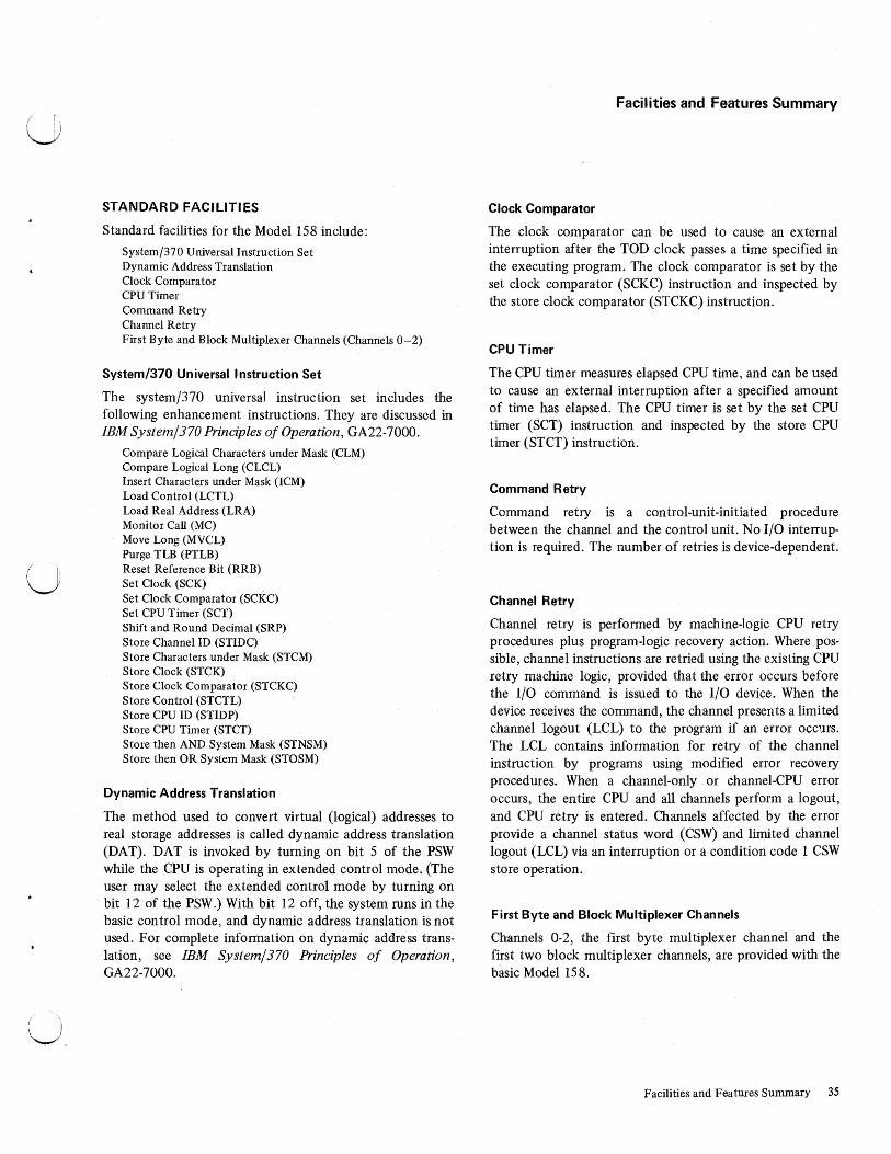
STANDARD FACILITIES
Standard facilities for the Model 158 include:
System/370 Universal Instruction Set Dynamic Address Translation Clock Comparator CPU Timer Command Retry Channel Retry First Byte and Block Multiplexer Channels (Channels 0-2)
System/370 Universal Instruction Set
The system/370 universal instruction set includes the following enhancement instructions. They are discussed in IBM System/370 Principles of Operation, GA22-7000.
Compare Logical Characters under Mask (CLM) Compare Logical Long (CLCL) Insert Characters under Mask (ICM) Load Control (LCTL) Load Real Address (LRA) Monitor Call (MC) Move Long (MVCL) Purge TLB (PTLB) Reset Reference Bit (RRB) Set Clock (SCK) Set Clock Comparator (SCKC) Set CPU Timer (SCT) Shift and Round Decimal (SRP) Store Channel ID (STIDC) Store Characters under Mask (STCM) Store Clock (STCK) Store Clock Comparator (STCKC) Store Control (STCTL) Store CPU ID (STIDP) Store CPU Timer (STCT) Store then AND System Mask (STNSM) Store then OR System Mask (STOSM)
Dynamic Address Translation
The method used to convert virtual (logical) addresses to real storage addresses is called dynamic address translation (DAT). DAT is invoked by turning on bit 5 of the PSW while the CPU is operating in extended control mode. (The user may select the extended control mode by turning on bit 12 of the PSW.) With bit 12 off, the system runs in the basic control mode, and dynamic address translation is not used. For complete information on dynamic address translation, see IBM System/370 Principles of Operation, GA22-7000.
Facilities and Features Summary
Clock Comparator
The clock comparator can be used to cause an external interruption after the TOD clock passes a time specified in the executing program. The clock comparator is set by the set clock comparator (SCKC) instruction and inspected by the store clock comparator (STCKC) instruction.
CPU Timer
The CPU timer measures elapsed CPU time, and can be used to cause an external interruption after a specified amount of time has elapsed. The CPU timer is set by the set CPU timer (SCT) instruction and inspected by the store CPU timer (STCT) instruction.
Command Retry
Command retry is a control-unit-initiated procedure between the channel and the control unit. No I/O interruption is required. The number of retries is device-dependent.
Channel Retry
Channel retry is performed by machine-logic CPU retry procedures plus program-logic recovery action. Where possible, channel instructions are retried using the existing CPU retry machine logic, provided that the error occurs before the I/O command is issued to the I/O device. When the device receives the command, the channel presents a limited channel logout (LCL) to the program if an error occms. The LCL contains information for retry of the channel instruction by programs using modified error recovery procedures. When a channel-only or channel-CPU error occurs, the entire CPU and all channels perform a logout, and CPU retry is entered. Channels affected by the error provide a channel status word (CSW) and limited channel logout (LCL) via an interruption or a condition code 1 CSW store operation.
First Byte and Block Multiplexer Channels
Channels 0-2, the first byte multiplexer channel and the first two block multiplexer channels, are provided with the basic Model 158.
Facilities and Features Summary 35

OPTIONAL FEATURES
The optional features for the CPU include: Direct control Channel-to-channel adapter Emergency power-off control (multisystem) Block multiplexer channels (channels 3, 4, and 5)* Second byte multiplexer channel (channel 4 )* Extended-precision floating-point OS/DOS compatibility 1401/1440/1460 and 1410/7010 compatibility 7070/7074 compatibility Virtual machine assist Power warning Main storage options (1,024K, l,536K, 2,048K, 3,072K, or
4,096K)* Integrated storage controls and two-channel switch for ISC 3213 printer attachment Multiprocessing Staging adapter 305 6 remote console attachment
*Refer to the configurator (Figure 1) for details on channel and main storage options.
Direct Control
The direct control feature provides two instructions, read direct and write direct, and six external interruption lines. The read and write instructions provide for the transfer of a single byte of information between an external device and the main storage of the system. Each of the six external signal lines, when active, sets up the conditions for an external interruption. Additional details are in IBM System/360 and System/370 Direct Control and External Interruption Features, OEM!, GA22-6845.
Channel-to-Channel Adapter
The channel-to-channel adapter feature allows the establishment of a loosely coupled multisystem via one control-unit position on the respective channels of the individual systems. Only one adapter may be installed on the Model 158; the attachment may be on either the byte or the block multiplexer channel.
Under program control, the channel-to-channel adapter can operate as two independent control units. Five commands, in addition to those supplied on System/360, are available to the programmer. Expanded checking facilities are also provided. Programs written for the System/360 adapter may be run if the additional features are not enabled.
Emergency Power-off Control (Multisystem)
Emergency power-off control is required on only one of the processing units, normally the largest, in any installation composed of more than one cable-connected processing unit and/or cable-connected units that can be operated offline.
Optionally, from two to as many as twelve EPO switches can be installed (refer to Figure 1). The emergency power-off feature interconnects EPO switches to provide, in effect, a single EPO switch.
36 S/370 Model 158 Functional Characteristics
Extended-precision Floating-point
Extended-precision floating-point includes instructions designed to handle extended-precision (28-hex-digit) floatingpoint operands. Extended-precision operands may also be rounded to long-precision format, and long-precision operands may be rounded to short-precision format. For additional details, see IBM System/370 Principles of Operation, GA22-7000.
OS/DOS Compatibility
The OS/DOS compatibility feature allows the user to run System/360 Disk Operating System (DOS) control programs (including multiprogramming) under control of the System/360 Operating System (OS) in a multiprogramming environment. Refer to Emulating DOS Under OS on IBM System/370, GC26-3777.
1401/1440/1460 and 1410/7010 Compatibility
The 1401/1440/1460 and 1410/7010 integrated emulator programs allow the Model 158 to execute programs and programming systems originally written for 14XX or 7010 systems. The compatibility feature adds special instructions and internal logic to the Model 158. The integrated emulator programs use these facilities and the available instruction sets to execute 14XX-type instructions in a multiprogramming environment. Unlike stand-alone emulators, integrated emulators must share the CPU and 1/0 devices with the operating system. In a system with multiprogramming capability, however, the time lost waiting for a shared resource is much less (on the average) than the time lost by a stand-alone emulator waiting for its 1/0 operations to be completed. This reduction in system wait time increases total system throughput.
7070/7074 Compatibility
The 7070/7074 emulation allows the Model 158 to execute programs and programming systems originally written for the IBM 7070 and 7074 Systems.
Virtual Machine Assist Feature
The virtual machine assist" (VMA) feature improves performance on the Model 158 that is using virtual storage systems running under VM/370. This improvement is achieved by significantly reducing the amount of time VM/370 spends in the real supervisor state. This reduction is accomplished by emulation (instead of software simulation) of certain privileged operation codes used by the VS system supervisor. Emulation is also used for shadow page table maintenance and for SVC interruption handling.
The VMA feature may not operate concurrently with the 7070/7074 compatibility feature. The system operator must determine at IMPL time whether VMA or 7070/7074 compatibility is to be loaded.
Release 2 of VM/370 provides programming support.

Power Warning Feature
The power warning feature, on the Model 158 supported by an uninterruptible power system, permits the use of controlled shutdown and recovery procedures following power line disturbances. When utility power drops 18 ± 2% below rated voltage, the feature provides an automatic interruption to the control program. Combined with OS/VS or OS/MVT programming, the power warning feature provides support for:
• Turning on the power warning bit
• Time delay before interruption
• User intercept option
• Main storage dump/restore
The uninterruptible power system provides a power reserve to take over the task of powering either the complete system, or critical components of the system, during line disturbances including complete loss of utility-furnished power. With an uninterruptible power system supporting the complete processing system, operation may continue during power failures as long as the interruption does not exceed the buffering capacity of the uninterruptible power system. The user intercept option permits the user to program (via an exit) procedures tailored to his operation.
The CPU, all channels, and control units and devices on only one channel are powered by a partial uninterruptible power system, and use of the user intercept option may be less attractive.
The elements of the power warning feature, which is field installable, are: 1. A vendor-supplied uninterruptible power system for
maintaining power to the entire or critical components of the system, and. a sensor to detect power line disturbances and generate a power warning signal.
2. Hardware modifications to the Model 158 to support the power warning machine-check interruption architecture.
3. Software support for the power warning machine-check interruption handler, including the dump .and restore programs and the user intercept option.
Operational Characteristics: The power warning is issued when utility voltage is reduced by 18 ± 2% for a duration greater than one-half cycle. The uninterruptible power system sensor signal remains active as long as the undervoltage condition exists, and causes the CPU to generate a soft machine-check interruption. This interruption is under the control of PSW bit 13 (Machine Check Interruption Mask), and bit 7 of control register 14 (Power Warning Sub-Mask).
If the user provides an uninterruptible power system for his complete computing system, the following events will then occur: 1. The interruption will branch to a timing routine to
determine if the power disturbance is transient. The
duration of this timing activity is a customer option and is limited by the uninterruptible power system capacity.
2. If the disturbance is transient, control can be returned to the machine-check handler and the system continues operation.
3. If the disturbance is determined to be non-transient, control is passed to either the dump routine or to the user intercept option.
4. If the dump routine is selected, when normal power is restored, system storage can be refreshed from the dump device. This storage information is then available to assist the user in recovery and restart procedures.
5. If the user intercept option is selected, the user is able to: a. Ride through the power line disturbance if it is of
short duration. b. Assess the reserve time left in his uninterruptible
power system to justify continued processing. c. Initiate his system quiesce procedures to terminate
operations within the limits of his UPS reserves. Such procedures must be developed by the user.
d. Transfer to the dump routine which terminates all processing and preserves the contents of storage for subsequent restart procedures.
If the user has a partial uninterruptible power system, during the processing of the power warning interruption, all channels are set to the channel interruption pending state. The channel on which the storage dump is to be performed must process the microcode-initiated channel error interruption. Interruptions are allowed from that channel only. Normal error retry procedures are used. The entire contents of storage are dumped, at which time the uninterruptible power system may be turned off to conserve reserve power. When full utility power is returned to the system, the main storage contents can be restored from the dump device.
Multiprocessing: In a tightly-coupled multiprocessing system, the power warning signal is sent to both CPUs. Masking in the individual CPUs determines if the interruption is processed or held pending. In MP mode all shared storage can be dumped by either CPU, depending on which one processes the interruption.
In uniprocessor mode, each CPU must process its own interruption. Only that storage configured to a CPU can be dumped by that CPU. If both CPUs require data retention in the uniprocessor environment, they must both have a control unit configured that has uninterruptible power system support.
Physical Planning: Installation of either a partial or full uninterruptible power system requires a significant amount of pre-installation planning. Specialists are required to determine uninterruptible power system specifications, space requirements, cable layout, etc. Users should allow six months to a year lead time prior to the desired installation date.
Facilities and Features Summary 37


Processing Unit
~--Two-chon ne I Switch
I I
Block Mpx Channel
Block Mpx Channel
Block Mpx Channel
Block Mpx Channel
*The second data path from each half of the two-channel switch may be logically connected to a channel on the host CPU or on another CPU.
g g
g g
g g
g g
g g
3333
g g g g g g
g g g g
g g g g g g
g g g g
g g g g g g
g g g ~
3330-1
Figure 20. Integrated Storage Controls and Two-channel Switch Showing Logical Maximum Configuration
Integrated Storage Controls (ISC)
The Model 158 integrated storage controls (ISC) feature provides for the attaclunent of up to eight IBM 3333 Disk Storage and Control Model l's. The IBM 3330 Disk Storage Model 1 can be attached· to provide a maximum of 64 disk drives, when the 32-drive expansion feature is attached.
The integrated storage controls execute DASD commands; the feature is program compatible with IBM 3830 Storage Control and IBM 3330 Disk Storage in the areas of data format, channel commands, permissible command sequences, and error recovery procedures.
The ISC contains two data and control paths, each of which is capable of attaching up to 32 disk drives (see
Figure 20). The two paths are logically independent, with completely overlapped operation, and each can attach to separate block multiplexer channels. There is some commonality for the two data and control paths. One kind of failure may cause both data and control paths to be inoperative.
The ISC is dependent on the 3158 Processing Unit and is clocked on the CPU meter.
Two-channel Switch
A two-channel switch feature is available that provides for attaclunent to an additional block multiplexer channel (see Figure 20). The paths may be attached to channels on
Facilities and Features Summary 37 .1

either the same or different CPUs. Channel switching and device reservation are controlled by the channel program. Tw0 special commands are associated with two-channel switch operation: device reserve and device release. Individual drives attached to the ISC may be reserved for the exclusive use of either of the two channels attached to the given ISC path.
32-Drive Expansion
This feature permits the attachment of two additional 3333 Disk Storage and Control Model 1 s and their associated 3330 Disk Storage Model 1 disk drives on each path of the integrated storage controls feature (see Figure 20). This doubles the number of available disk drives on the ISC, making a maximum of 64. A prerequisite for 32-drive expansion is the control store extension feature, which provides additional control storage for microprogram use.
Staging Adapter for /SC
This optional feature for the ISC permits expansion of the addressing capability of each ISC path to a maximum of 64 unique addresses. The adapter allows direct attachment of the IBM 3850 Mass Storage System to a Model 158, and provides the same functions as the IBM 3830 Storage Control Model 3. The expanded capability that the adapter provides is independent of the number of 3330 Disk Storage drives attached to the ISC. Attachment of the staging adapter requires attachment of the ISC control store extension, and precludes attachment of 3340 Disk Storage drives to the ISC.
Facilities
The integrated storage controls provide or support the following standard facilities:
• Command Retry
• Multiple Requesting
• Multiple Track Operation
• Record Overflow
• End-of-File
Command Retry: Command retry is a channel-storage control procedure that causes an improperly executed command in a channel program to be automatically retried. The reexecution does not cause an 1/0 interruption, and programmed error-recovery procedures are not required.
Multiple Requesting: Use of block multiplexer channels and disk drives with rotational position-sensing capabilities allows the ISC and attached disk drives to disconnect from the channel during mechanical delays resulting from execution of arm-positioning seek sector or set sector commands. Reconnection is attempted when the access mechanism is positioned at the desired track, or when the specified rotational position has been reached.
38 S/370 Model 158 Functional Characteristics
During the time the channel and the ISC are disconnected, the CPU is free to initiate I/O operations on other drives attached to the ISC even though the disconnected channel program is not completed. Thus, separate channel programs may be operating .simultaneously on each drive attached to the storage control.
Multiple Track (MT) Operation: On all search and most read commands, the ISC can automatically select the next sequentially numbered head on a disk drive. This eliminates the need for seek head commands in a chain of read or search commands.
Record Overflow: The record overflow function provides a means of processing logical records that exceed the capacity of a track. When the system is using overflow records, the cylinder boundary is the factor limiting the size of the record.
A special channel command (Write Special Count, Key, and Data) is used to format the disk pack for record overflow operation.
End-of File: An end-of-file record, used to define the end of a logical group of records, is written by executing a Write Count, Key, and Data command with a data length of zero. Execution of this command causes the ISC to direct the addressed drive to write a data area consisting of one byte of zeros.
When the end-of-file record is processed, detection of the zero data length causes unit exception status to be generated.
Statistical Usage/Error Recording
The ISC maintains a statistical· data record of usage and error information for each attached logical device. The usage information provides an accumulated count of the total number of access motions, and the total number of seek errors, correctable data errors, and uncorrectable data errors that were recovered by the ISC retry procedure. Also included in the error information is the total number of command and data overrun conditions that were retried by the ISC.
The usage/error information is sent to the system logout area periodically. The transfer takes place on the next start I/O issued to the device having outstanding usage/error information. Each of the usage/error counters is reset to zero after the counter infqrmation is transferred to the channel.
Storage Control Diagnostics
To provide maximum facility availability, the ISC can execute diagnostic tests on a drive concurrently with normal system operation on the remaining disk drives. This mode of operation allows servicing personnel to diagnose
/~ ! )

u
( I
\_.,)
and repair most disk drive failures while the facility continues to operate other attached drives. The ISC provides a transient block of 512 bytes (128 words) of control storage to allow temporary residence for a specific diagnostic test.
The transient area is loaded by the system under control of the Online Test Executive Program (OLTEP). A special command (diagnostic write) loads a selected test into control storage and instructs the storage control to execute the test. This loading and execution may also be initiated from the servicing panel.
After the test, error-message information or test results are transferred from the ISC to main storage by a read diagnostic status 1 command. If the servicing panel is used, the test results are displayed on the servicing panel indicators.
Configuration Control
Operator-accessible switches are provided for configuration control of each ISC data and control path (see Figure 21). The ISC can operate with a given channel only when the respective interface switch is set to ON. The multitag switches determine how the device end (generated by the drive in a not-ready-to-ready sequence) is provided to the channel.
When the multitag switch is set to ON, a di~ drive is available to a channel after the channel clears the device end generated by the drive on a not-ready-to-ready sequence. Before any other channel can use the disk drive, it must also accept the not-ready-to-ready sequence device end.
When the multitag switch is set to OFF, a disk drive is made available to all channels after one of the channels clears the device end generated by the drive in a not-readyto-ready sequence.
Input/Output Operations
The following text contains a general description of 1/0 operations related to the ISC and its attached disk storage units. For detailed information regarding the central processing unit and channel program control of 1/0 operations, refer to IBM System/370 Principles of Operation, GA22-7000.
Unit Selection and Device Addressing: The 1/0 address of each ISC data and control path and its attached drives is designated by an eight-bit binary number in an 1/0 instruction. 1hese addresses consist of three parts: (1) The ISC data and control path address (determined by servicing personnel at installation time) in bits 0, 1, 2, and 3; (2) the address of the 3333 Disk Storage specified in bit 4; and (3) the addresses of the attached 3330's specified in bits 5, 6, and 7. With 32 drives installed on each path, bits 0, 1, and 2 are used to designate the ISC data and control path address.
ISC CONFIGURATION CONTROL
!SC l
INTERFACE A INTERFACE B MULTITAG
gON OFF
;ON OFF
gON OFF
ISC 2
INTERFACE A INTERFACE B MULTITAG
~ON OFF
~ON , OFF
~ON OFF
Figure 21. Configuration Control Switches with Two-channel Switch Feature
The 3333 Disk Storage and Control address is specified in bits 3 and 4; bits 5, 6, and 7 retain their same function.
The ISC accepts any drive address from 000 to 111. If the specified drive is either offline or not attached, the attempted operation is terminated with unit check status. Multiple responses to an address owing to duplicate logical address plugs or hardware failures also cause the operation to be terminated.
Channel Commands: The command set used to perform operations with the ISC is identical to that used with the 3830 Model 1/3330 Disk Storage Facility.
Refer to Reference Manual for IBM Integrated Storage Control, GA26-1620, for a description of commands and sense data.
Multiprocessing
The use of multiprocessing permits two Model 158 systems to function with a single operating system in a shared main storage environment, and provides shared 1/0 and floating storage addressing capabilities.
Each 3158 Processing Unit can function independently when in the uniprocessor (UP) mode.
The Model 158 MP system consists of two CPUs (both MP models having equal storage), an IBM 3058 Multisystem Unit, and 1/0 devices with shared and nonshared control units. The system has shared main storage, as well as configuration, partitioning, and synchronization facilities.
System availability is increased through better use of resources. Required maintenance may be performed with reduced effect on the system operations. When servicing is
Facilities and Features Summary 39

required on the MP system, a maintenance subsystem consisting of a processor, channels, adequate storage; and 1/0 can be configured to perform the maintenance function. In general, this is accomplished by use of manual reconfiguration and vary offline facilities.
Both CPUs of an MP system must have identical storage capacity. All features announced on the Model 158 are available when installed on both CPUs. Channels are dedicated to the CPUs to which they are attached; devices on them may be shared if the two-channel switch feature is installed.
The Model 158 multiprocessing system is available in the following storage sizes:
l,024K
2,048K
3,072K
4,096K
6,144K
8,192K
Logical Units of Floating Multiprocessors Units Storage Addressing
2 Model 4 256K logical units with 512K MP ls physical partitioning
2 Model 4 512K logical units with l,024K MP2s physical partitioning
2 Model 6 512K logical units with 1,5 36K MP3s physical partitioning
2 Model 8 512K logical units with 2,048K MP4s physical partitioning
2 Model 6 1,024K logical units with 3 ,072K MP5s physical partitioning
2 Model 8 l,024K logical units with 4,096K MP6s physical partitioning
The physical dimensions of the Model 158 MP system are equivalent to two single-CPU systems with the addition of the 3058 Multisystem Unit on which the configuration control panel is mounted (Figure 22).
CPU A 3158 Configuration Control Panel 3158 CPU B
Figure 22. Example of a Model 158 MP System (Plan View)
The following items discuss various areas in which multiprocessing differs from single-CPU processing, both architecturally and in hardware implementation.
Prefixing
Each CPU in a shared storage multiprocessing environment requires an area of storage to be used for permanently assigned locations and logout areas. Since there is only one set of storage locations with these addresses in shared
40 S/370 Model 158 Functional Characteristics
main storage, a means of assigning them to two different storage areas, one for each CPU, is necessary. Prefixing is the technique used.
Prefixing, in the Model 158, provides the means of assigning real addresses 0 to 4095 to any storage area, starting at an address that is a multiple of 4096. Each CPU has a private page frame allocated to it in virtual queue space for use as a permanent storage area (PSA). The real storage address for each CPU is placed in bits 8-19 of the prefix register located in the storage control unit (SCU) of that CPU. Note: Real address 0 to 4095 for each CPU is used by the nucleus initialization program (NIP) and other CPU functions. The prefix register may be altered or displayed by use of the alter/display function (see "Console Functions'').
Prefixing operates as follows: Whenever a CPU references a storage address in the range of 0 to 4095 (the high-order twelve bits, 8-19, of the effective storage address are zeros), the contents of the prefix register for that CPU replace bits 8-19 of the effective address. The new address will then point to a location in the PSA of that CPU. This is forward prefixing. When a CPU references an address in the 4K block that is pointed to by its prefix register (that is, an address in its own PSA), zeros are substituted for bits 8-19 of the effective address so that an address range of 0 to 4095 results. This is reverse prefixing. The prefix is applied to references made by the CPU including hardwaregenerated addresses such as the interval timer, PSWs, etc. References made by a channel to channel command words and I/O data are not prefixed.
Interprocessor Program Communication
Interprocessor program communication is accomplished by use of the signal processor (SIGP) instruction and the hardware interface between the CPUs. The CPU receiving the signal decodes the order, performs the specified operation, and responds to the signalling CPU. (Note that a CPU may signal itself by inserting its own address in the instruction.) Nine orders are used for interprocessor communication. They are specified in bit positions 24-31 of the second operand address of the SIGP instruction and are encoded as follows:
Code
(00} 01 02 03 04 05 06 07 08 09
(OA-FF)
Order
(Invalid) Sense External Call Emergency Signal Start Stop Restart Initial Program Reset Program Reset Stop and Store Status
(Invalid)
Details concerning the signal processor instruction and other new instructions, namely: store CPU address (STAP),
/~ I, /

u
I U: I\
set prefix (SPX), store prefix (STPX), compare and swap (CS), compare double and swap (CDS), insert PSW key (IPK), set PSW key from address (SPKA), and clear I/O (CLRIO) can be found in IBM System/370 Principles of Operation, GA22-7000.
Shared Storage
Communication between CPUs is switched active when both CPUs have read a valid shared storage configuration from the configuration control panel. This ensures that all references to shared storage access the most current data.
Malfunction Alert
Whenever a CPU enters the check stop state, a malfunction alert signal is sent to the other CPU. The receiving CPU halts SCU-to-SCU communication to record the interruption and provide continued processing. A SIGP initial program reset removes the check stop state and the storage protect keys are validated.
Time-of-Day (TOD) Clock
In MP mode, the oscillator pulse in CPU A (hex address 0000) is broadcast to CPU B (hex address 0001) in order to run both clocks as one. In order to facilitate the software synchronization of the time-of-day clocks, a sync pulse each second is also broadcast between storage control units. This pulse can be used to restart the TOD clock. In UP mode, the clocks run independently.
Configuration Control Panel
The configuration control panel located on the configuration control unit controls the system mode, main storage and I/O unit allocation, floating storage addressing, and system configuration. The panel contains the system mode switch, valid configuration lights, the enter configuration (ENTER CONFIG) pushbutton, a floating address switch and two storage allocation switches for each storage unit, and I/O unit allocation switches. (See Figure 23 .)
System Mode Switch
The system mode switch is used to allow or disallow communication between CPUs in conjunction with the enter configuration pushbutton. If the ENTER CONFIG pushbutton is pressed when the switch is in the MP position, the signals associated with communication between CPUs can be transmitted. If the switch is set to UP, no signals can be transmitted between CPUs.
Storage Allocation Switches
Two storage allocation switches, one per CPU, are associated with each floating storage address rotaiy switch.
Each storage allocation switch enables or disables the operation of the associated CPU with the storage unit when the enter configuration pushbutton is pressed.
Floating Storage Addressing
There is one floating storage address rotary switch per storage range assignment. Address ranges in increments of 256K, 512K, or 1,024K may be assigned, depending on the total storage capacity.
Enter Configuration Pushbutton
The enter configuration pushbutton is used to enter the states of the system mode switch, the storage allocation switches, and the floating storage allocation switches into the CPUs.
Valid Configuration Indicators
Two valid configuration indicator lights, one for each CPU, are located on the configuration control panel. They indicate whether a valid system configuration has been set on the panel. Pressing the enter configuration pushbutton has no effect on a CPU if its valid indicator is off.
The indicators are turned off if:
• The system mode switch is set to MP and more than one floating storage address switch is set to one address range.
• Power is off on one CPU (that CPU's indicator will be turned off).
• A system is configured with storage but without a storage unit 'O'.
• The system mode switch is set to UP and a storage unit is assigned to both CPUs.
• The system mode switch is set to MP and a storage unit is assigned to one CPU but not to the other.
I /0 Allocation Switches
Up to 28 pairs of I/O allocation switches are available; of these, 14 pairs are optionally available. With the twochannel switch and remote switch attachment features installed, these switches provide for the sharing of control units. They operate independently of the enter configuration pushbutton in enabling or disabling the control units for the particular CPU and channel.
Configuration Restrictions
Before configuring a CPU into the system, the CPU being brought into the running system must have had the reset/ clear function invoked manually.
Facilities and Features Summary 41

('\ ~ '.
~~ID§! 'i I
i
~ (S:D
m(S7>
(g~r~ [S:D~IDal "' .!!! "'.!!! (SD ~ ~ i ~ UJ 0
.:i:(Sp .:i:[g @in ~ DCJ @?
.......
[Sn "'
[5.n
"' [5:n .... [Si>
"' @?~ID§! @?
@? ~ [5:r>
@m~ @m~ i I "'.2! [S:D [S:o
] ] ;:;:;
.:i:[S:D .:i:[Sl> [S:D2 [S:o v LO
[I? ~ID§I [5:o
(/) [5:o E ~ (/) [S:o .>.
(j)
{!. [5:o
® m(Sp @ m[Sl>
0 [5:o
i J .... ~ ~ :::::: ..5 g
<I:~ <I:~
()
(/) 1::9 [5:o E
~ en [I? [5:o >.
(j)
® {!. @m~ [S:D [5:o
1 J Q) [5:o Cl <I:~ c i... 0 [5:n 0 §> -(j)
[S:D (5:D
[5:n cg.
~ [5:o ....
(9 JO§! [5:o
[St> "'0 [S:o
(/) [S:D [5:o E
J.,o Q) -~~@
en ~ [5:o .>. c
L4'° (j)
.Q c 0 [5:;n [5:o i... ..... <I: .:i:"' al :::J a:: C>
Cl wU:: 0 ~cs;z,j ][So .... :z .;: Zo c:
....,._, ~~ .Q_
0 u
Figure 23. Model 158 MP Configuration Control Panel
42 S/370 Model 158 Functional Characteristics

u
u
In order to vary a CPU online, a SIGP initial program reset function must be issued by the operating system before restarting the "varied on" CPU. This must be done to synchronize the storage protection keys.
Failure to observe these restrictions will cause unpredictable results.
In addition, when performing the vary online function of a storage range, the operating system must validate that storage increment before using the new storage. Otherwise, residual errors may result in system damage. Set key instructions must be issued for the storage range varied online before using the new storage.
Manual Controls
All manual controls of the multiprocessor system function as in the uniprocessor except system reset, clear control switch, load, and clock security switch. When in MP mode, the signals are propagated to the other CPU. The following table summarizes the effects of reset, reset clear, IPL, and IPL clear functions:
Effect Function Local Remote
(a) System reset (normal) Program reset Program reset
(b) System reset (clear) System clear Initial program reset
(c) IPL (normal) Initial program Program reset reset
(d) IPL (clear) System clear Initial program reset
(e) PSW restart Initial program Program reset reset
When the system is operating in MP mode, the TOD clock is secure only when the clock security switches are secure on both CPUs. Both TOD clocks are enabled for setting if either of the clock security switches is in the enable set position.
System Control Panel Features
The system control panel (Figure 5) in a 3158-3 multiprocessing system provides additional capability, through the use of the remote/local clock switch and the remote clock indicator.
Remote/Local Clock Switch
This two-position lever switch allows main storage of the local CPU to be synchronized and timed with the clocks of the remote CPU. (The terms local and remote are relative. The local CPU, for example, is the one whose control panel is actually being operated; the remote CPU is, at that time, the other CPU.) The switch in the remote position (up) enables the remote CPU (and a segment of the local CPU's main storage, if desired) to stay online. The local CPU and console may then be powered-down for maintenance, while main storage of the local CPU remains powered-up and available to the remote CPU. In normal operation, this switch is in the local position (down).
Remote Clock Indicator
Used in conjunction with the remote/local clock switch, this indicator lights when the remote clocks are being used to clock main storage of the local CPU.
Facilities and Features Summary 43

Appendix A. EBCDIC Interface Code
~ 00 01 x Q) 00 01 10 11 00 01 10 Bits I
4567 ~ 0 1 2 3 4 5 6
0000 0 SP & -0001 1 I 0 0 1 0 2
0 0 l 1 3 0 100 4
0 101 5 NL
0 1 1 0 6
0 1 1 1 7 1000 8
100 1 9 EM
101 0 A ¢ !
101 1 B $ I
1 100 c DUP < * %
1 101 D ( ) -
1 1 1 0 E FM + ; >
1 111 F I ---, ?
Table 1. 1/0 Interface Code-EBCDIC
44 S/370 Model 158 Functional Characteristics
10
11 00 01 10 11
7 8 9 A B
a i b k s
c I t
d m u
e 11 v
f 0 w
g p x h q y
i r z
: #
@ I
;::
11
11
00 01
c D
A J B K
c l D M
E N
F 0
G p
H Q
I R
10
E
s T u y
w x y
z
11
F
0
1 2
3 4
5
6
7 8
9
f.c-
14-
!+-
Bits 0, 1
Bits 2, 3
Hex 0
() I

u
u
Appendix B. Instruction Times for System/370 Model 158
These timing formulas show, in microseconds, the approximate time required to execute instructions in the System/ 370 Model 158. Because channel response time varies widely with the type of 1/0 device used, the times for the 1/0 instructions are not included. No CPU degradation due to channel interference is assumed.
These formulas are subject to change d\.l.e. to subsequent engineering change activity.
TIMING ASSUMPTIONS
The following assumptions were used in develOping the instruction timing formulas:
General
1. No delay occurs during instruction execution because of conflicts caused by 1/0 or other asynchronous operation.
2. No program interruptions occur Q.uring the execution of the instruction (including overflow, underflow, and significance).
3. The instruction fetch time is overlapped with the execution of the previous instruction if the instruction buffer is not empty.
4. All operands and instructions are in the buffer star.age 90 percent of the time and in the backing storage 10 percent of the time, unless otherwise assµmed.
5. All data fetches are on appropriate boundaries; that is, the operands are on integral multiples of operand length. No boundary alignment is required. If boundary alignment should be required, the instn,iction times will be significantly longer.
6. The interval timer adds an additional 795 micros~conds to the instruction times every I-second of elapsed time.
7. The CPU timer adds an additional 4.5 microseconds to the instruction times every I-second of elapsed time.
8. Each instruction time is increased by its share (which varies with the instruction type) of the time required to fill the instruction buffering registers if they should become drained during instruction processing,
9. The times do not include the local execution mode of the OS/DOS compatibility feature.
10. The instruction times do not include additional translation time for relocate mode. Translations are contained in the translation look aside buffer (TLB) 100 percent of the time.
The time in microseconds that is added to the CPU select time when translation is not in the TLB is shown in the table below:
Page in Buffer Storage
Pag~ i!l-Backing Storage
Segment In Latch
0.690
1.465
Segment Not in Latch Segment In Segment In Buffer Backing Storage
1.150 1.725
1.725 2.300
11. All ~Xtype instructions are 0.115 microsecond faster if either the base or the index register is zero.
12. In a test and set (TS) operation, the bit tested is a 1 in 50 percent of the cases.
13. Rounding occurs after a rounding operation 50 percent of the time.
SS-Format Instructions
1. Operand 1 and operand 2 are both in the buff er 7 5 percent of the time. Operand 1 or 2 is in the buffer 20 percent of the time. Both operand 1 and operand 2 are notin the buffer 5 percent of the time.
2. The operands of the VFL operations do not overlap. 3. For the move character long (MVCL) instruction, 50
percent of the data fetches and all of the data stores are tp main storage.
4. For the pack (PACK) instruction, the length ofoperand 2 is two times the length of operand 1. The length does not include the sign byte.
5. For the unpack (UNPK) instruction, the length of operand l is two times the length of operand 2. The length does not includ~ the sign byte.
6. For decimal add (AP), subtract (SP), and zero and add (ZAP) operations, the length of operand 1 is greater than or equal to the length of operand 2. No recomplementation occurs for the AP and SP operations.
7. The multiply decimal and divide decimal instructions are data dependent and the calculated instruction times will vary by a significant amount for different data combinations .
. 8. In edit (ED) and edit and mark (EDMK) operations, 75 percent of the pattern bytes are digit-select.
Appendix B 45

Floating-Point Instructions
I. All floating-point numbers are already in normalized form.
2. All floating-point instruction times are data dependent; they depend on the number of hexadecimal digits that are preshifted due to exponent difference and postshifted for normalization and. fraction overflow, as well as the number of times that .recomplementation of a result occurs, and any sign difference. The times are given to one decimal point for these instructions to show that the time is data dependent and will vary by a significant amount. The times given include the following weighted averages for the listed variables (recomplementation is not included):
Add and Subtract Instructions
Time (Microseconds)
0.23 0.16 1.35 0.27 0.24 0.55 0.06
Operation
Preshift of long operands Preshif t of short operands Preshift of extended operands Postshift of normalized long operands Postshift of normalized short operands Postshift of extended operands Sign difference
Compare Instructions
Time (Microseconds) Operation
0.23 0.16 0.12
Preshif t of long operands Preshift of short operands Sign comparison
Multiply and Divide Instructions
Time (Microseconds)
O.o? 0.12 0.12 0.23 0.06
Operation
Postshift of multiply long operands Postshift of multiply short operands Postshift of multiply extended operands Postshift of divide long operands Postshift of divide short operands
3. The times required for preshifts and postshifts are:
Add and Subtract Instructions
Time (Microseconds)
0.230 1.150 0.805 1.035
Operation
Each preshif t of long or short operands First preshift of extended operands Subsequent preshifts of extended operands First postnormalization of long operands
46 S/370 Model 158 Functional Characteristics
Time (Microseconds)
0.690 0.920 0.805 0.345 1.265 0.920 1.495
Operation
Each subsequent postshift of long operands First postnormalization of short operands Each subsequent postshift of short operands Fraction overflow for long or short operands First postnormalization of extended operands Subsequent postshifts of extended operands Fraction overflow for extended operands
Compare Instructions
Time (Microseconds) Operation
0.230 Each preshift of long or short operands
Multiply and Divide Instructions
Time (Microseconds)
0.345 0.575 0.575 0.460 0.115
Multiprncessing
Operation
Each postshift of multiply long operands Each postshift of multiply short operands Each postshift of extended operands Each postshift of divide long operands Each postshift of divide short operands
I. All the timing assumptions for non-MP models apply as well for the MP models.
2. In UP mode, non-MP-model instruction times apply when each CPU is assigned its main storage.
For statements 3 through 6, assume that all main storage is on-line and that both CPUs are running. 3. In UP mode, when one CPU is assigned only the main
storage of the other CPU, storage instruction times can increase as much as 0.230 microsecond per storage reference.
4. In UP mode, when one CPU is assigned only one-half its main storage, storage instruction times increase as much as 0.400 microsecond per storage reference.
5. In UP mode, when one CPU is assigned all its main storage and one-half the main storage of the other CPU, storage instruction times increase as much as 0.3cl5 microsecond per storage reference.
6. In MP mode, when both CPUs are assigned all the available main storage, storage instruction times increase as much as 0.515 microsecond per storage reference. Main storage result-storing instructions increase as much as 0.790 microsecond per reference. Also, the ISK, SSK, and RRB times can increase as much as 1.495 microseconds.
()

( ,, \_)!
LEGEND FOR TIMING FORMULAS
B
BT =
cc
=
CM =
Cl =
=
DL =
DR
DW =
DWI =
DW2 =
E =
EC = =
FO = =
l = =
12
M = =
Number of bytes processed. The terms B/8 and B/256 must be rounded to the next whole number.
1 If the branch is taken. 0 Otherwise.
If an unsuccessful branch is caused only by the branch-to register being zero.
0 Otherwise.
0 If the fields compare. 1 Otherwise.
If operand 1 crosses a doubleword boundary.
0 Otherwise.
Number of decimal digit positions to be shifted left.
Number of decimal digit positions to be shifted right.
Number of doublewords processed, not rounded.
Number of doublewords in operand 1, not rounded.
Number of doublewords in operand 2, not rounded.
Time for the subject instruction, which is executed by the 'execute' instruction. The instruction time is decremented by 0.115 microsecond if no modification of the instruction is re.quired.
1 For EC mode. 0 Otherwise.
1 If the fraction is zero. 0 Otherwise.
1 If program interrupt is taken. 0 Otherwise.
Contents of the 12 field expressed as a decimal number 0-15.
1 If the mask is not all zeros. 0 Otherwise.
MB =
N =
NRD
NO
NI
N2
N3
N8
N16
N21
PNM = =
Pl =
P2 = =
P3
Number ofl-bits in the mask.
Total number of bytes in operand 1 for instructions with a single length field. The terms N/4, N/8 and N/16 must be rounded to the next whole number.
1 If no rounding is required. 0 Otherwise.
Number of high-order hex zeros in operand 1.
Total number of bytes in the first operand (destination). The terms Nl/2, Nl/4 and Nl/8 must be rounded to the next whole number.
Total number of bytes in the second operand (source). The terms N2/4 and N2/8 must be rounded to the next whole number.
- 1 If only one byte is to be processed. 0 Otherwise.
If left shift is required. If N 1 is equal to or greater than two times the shift amount.
1 If N 1+1 is equal to or greater than two · times the shift amount and the I3 field is not equal to zero.
0 Otherwise.
1 If NI is equal to 2 or 16. 0 Otherwise.
0 If N2 is greater than N 1. 0.75 IfNl is equal to N2. 1 Otherwise.
If postnormalization is required. 0 Otherwise.
0 If operand 1 is positive. 1 Otherwise.
0 If operand 2 is positive. 1 Otherwise.
If the signs of operand 1 and 2 are different.
= 0 Otherwise.
QWB = Number of quadword boundaries crossed.
Appendix B 4 7

R Number of registers to be loaded or stored. so 0 If no I-bit shifts are taken. The term R/4 must be rounded to the next 1 Otherwise. (~ whole number. i /
SI Number of I-bit shifts remaining after com-RO 0 If operand 2 points to an address on a pietion of the 4-bit shifts.
doubleword boundary. 0 If an odd number of registers is to be 83 If more than eight 4-bit shifts are to be
loaded or stored. taken. :;:: Otherwise. 0 Otherwise.
RI 0 If an even number of registers is to be 85 If shift is greater than three.
loaded or stored. 0 Otherwise.
I Otherwise. 86 = I If two I-bit shifts are taken.
R2 0 If the number of registers to be loaded or 0 Otherwise.
stored is greater than 2. 87 If two or more 4-bit shifts are taken. = I Otherwise.
= 0 Otherwise.
s I If no 4-bit shifts are taken. S9 I If three I -bit shifts are taken. 0 Otherwise. :;: 0 Otherwise.
48 S/370 Model 158 Functional Characteristics

SYSTEM/370 MODEL 158 INSTRUCTION TIMINGS
Instruction Op Instruction Format Code Mnemonic Time (Microseconds)
Add RR IA AR 00.495
,•, Add RX SA A 00.933
Add Decimal SS FA AP 02.315+00.11S(N1)+00.430(N1 /4) +00.430(N2/4) + 00.660 (C 1)
Add Halfword RX 4A AH 01.163 + 00.230 (P2)
Add Logical RR IE ALR 00.380
Add Logical RX SE AL 00.703
Add Normalized (Extended) RR 36 AXR 05.0
Add Normalized (Long) RR 2A ADR 02.2
Add Normalized (Long) RX 6A AD 02.5
Add Normalized (Short) RR 3A AER 02.0
Add Normalized (Short) RX 7A AE 02.4
Add Unnormalized (Long) RR 2E AWR 02.0
Add Unnormalized (Long) RX 6E AW 02.2
Add Unnormalized (Short) RR 3E AUR 01.8
Add Unnormalized (Short) RX 7E AU 02.1
AND RR 14 NR 00.840
AND RX 54 N 01.163
AND (Immediate) SI 94 NI 00.829
AND (Characters) SS D4 NC 00 .406+00 .11S(N)+OO.702(N /4) +00 .5 93(N/ 8)
Branch and Link RR 05 BALR 00.725 + 00.288(BT)
Branch and Link RX 45 BAL 01.163
Branch on Condition RR 07 BCR 00.380+00.288(BT)+00.345(CC)
Branch on Condition RX 47 BC 00 .5 30+00 .288(BT)
Branch on Count RR 06 BCTR 00.380+00.403(BT) , I• ui j
Branch on Count RX 46 BCT 00.645+00.288(BT)
Appendix B 49

Branch on Index High RS 86 BXH 00.875+00.518(BT)
Branch on Index Low or Equal RS 87 BXLE 00 .990+00 .403(BT) n Compare RR 19 CR 00.380
Compare RX 59 c 00.703
Compare and Swap RS BA cs 01.163+00.l lS(CM)
Compare Decimal SS F9 CP 02.315+00.11S(B)+00.430(N1/4) CP +00.345(Cl) + 00.430(N2/4) CP +Ol .610(1-N21)-00.920(P3)(1-N21)
Compare Double and Swap RS BB CDS 01.393+00.403(CM)
Compare Halfword RX 49 CH 00.933+00.230(P2)
Compare Logical RR 15 CLR 00.380
Compare Logical RX 55 CL 00.703
Compare Logical SI 95 cu 00.588
Compare Logical SS DS CLC 00.785+00.11 S(B) +00.702(DW) +00.914(B/8)
Compare Logical Long RR OF CLCL 00.725+00.368(B) +00.529(B/8) (~ +04.037(B/256) I
Compare Logical Characters RS BD CLM 00.703+01.035(M)+OO. l l S(MB) Under Mask
Compare (Long) RR 29 CDR 02.3
Compare (Long) RX 69 CD 02.5
Compare (Short) RR 39 CER 02.1
Compare (Short) RX 79 CE 02.4
Convert to Binary RX 4F CVB 02.198
Convert to Decimal RX 4E CVD 02.370
Divide RR ID DR 09.350
Divide RX SD D 09.903
1·. Divide Decimal SS FD DP 06.535+02.87S(N1)"'"03.450(N1 /4)
-04.600(N2)+02.875(N2)(Nl-N2)
Divide (Long) RR 2D DDR 23.2 n Divide (Long) RX 6D DD 23.3
50 S/370 Model 158 Functional Characteristics

Divide (Short) RR 3D DER 08.6
Divide (Short) RX 7D DE 08.9
Edit SS DE ED 0 l. l 30+01.668(N)+02.128(DW) -Ol.323(Cl)
Edit and Mark SS DF EDMK 01.130+01.668(N)+02.128(DW) -Ol.323(C 1)
Exclusive OR RR 17 XR 00.840
Exclusive OR RX 57 x 01.163
Exclusive OR (Immediate) SI 97 XI 00.829
Exclusive OR SS D7 xc 00.406+00.l 15(N)+00.702(N/4) +o0.593(N/8)
Execute RX 44 EX 01.623 + E
Halt Device SI 9E01 HDV Indeterminate
Halt 1/0 SI 9EOO HIO Indeterminate
Halve (Long) RR 24 HDR 01.070 + 00.690(PNM)
Halve (Short) RR 34 HER 00.840 + 00.575(PNM)
Insert Character RX 43 IC 00.818
Insert Characters Under Mask RS BF ICM 00.703+01.035(M) +00.l 15(MB)
Insert Program Key SI B20B IPK 01.565 ~
Insert Storage Key RR 09 ISK 01.185
Load RR 18 LR 00.380
Load R.X 58 L 00.588
Load Address RX 41 LA 00.530
Load and Test RR 12 LTR 00.380
Load and Test (Long) RR 22 LTDR 00.610
Load and Test (Short) RR 32 LTER 00.610
Load Complement RR 13 LCR 00.495
Load Complement (Long) RR 23 LCDR 00.840+00.115(FO) i
v Load Complement (Short) RR 33 LCER 00.840+00.1l5(FO)
Appendix B 51

Load Control RS B7 LCTL 11.915+00.483(R) -Ol.955(R2) +00.345(EC) n
Load (Long) RR 28 LDR 00.495
Load (Long) RX 68 LD 00.703
Load Halfword RX 48 LH 00.933+00.230(P2)
Load Multiple RS 98 LM Ol .070+00.207(R)+00.023(Rl) +00. l 15(RO)
Load Negative RR. 11 LNR 00.380
Load Negative (Long) RR 21 LNDR 00.610+00.11 S(FO)
Load Negative (Short) RR 31 LNER 00.610+00.11 S(FO)
Load Positive RR 10 LPR 00.380+00.115(P2)
Load Positive (Long) RR 20 LPDR 00.610+00.11 S(FO)
Load Positive (Short) RR 30. LPER 00.610+00.11 S(FO)
Load PSW SI 82 LPSW 03.072
Load Real Address RS Bl LRA 05.590
rl Load Rounded (Extended to Long) RR 25 LRDR 01.415 - 00.230(NRD)
Load Rounded (Long to Short) RR 35 LRER 01.185 - 00.345(NRD)
Load (Short) RR 38 LER 00.380
Load (Short) RX 78 LE 00.703
Monitor Call SI AF. MC 01.113+00. l 15(12)+07 .830(1) +02.576(EC)
Move (Immediate) SI 92 MVI 00.530
Move (Characters) SS D2 MVC Formula is dependent on length: 16 Bytes or Less 00;784+00.115(N)+00.702(N/4)
+00.092(DW)
More than 16 Bytes Ol .797+01.27l(N/8)-00.805(N/16)
Move Long RR. OE MVCL O l .070+00.633(B/8) +00.547(N2/8) +04.439(B/256)
Move Numerics SS D1 MVN 00 .406+00. i 1 S(N)+OO. 7 02(N I 4) +00.593(N/8)
Move with Offset SS Fl MVO· 00.923+00.196(Nl)+00.782(Nl/4) rn +00.403(C 1)+00.115(N3)
52 S/370 Model 158 Functional Characteristics

Move Zones SS D3 MVZ 00 .406+00 .11S(N)+OO.702(N I 4) u +00.593(N/8)
Multiply RR IC MR 01.645
Multiply RX SC M 01.991
Multiply (Extended) RR 26 MXR 19.0
Multi ply Decimal SS FC MP -01.030+04.600(Nl)-03.330(Nl/4) +02.87S(DW1)-01.1 SO(NO)
Multiply Halfword RX 4C MH 01.416
Multiply (Long) RR 2C MDR 03.2
Multiply (Long) RX 6C MD 03.9
Multiply (Long to Extended) RR 27 MXDR 08.7
Multiply (Long to Extended) RX 67 MXD 09.9
Multiply (Short) RR 3C MER 01.8
Multiply (Short) RX 7C ME 02.1
OR RR 16 OR 00.840 1 u OR RX 56 0 01.163
OR (Immediate) SI 96 01 00.829
OR (Characters) SS D6 oc 00.406+00 .11S(N)+OO.702(N I 4) +00.593(N/8)
Pack SS F2 PACK 01.5 85 + 00.230(N 1 /2) -00.012(DWI-Cl)
Purge TLB SI B20D PTLB 09.155
Read Direct SI 85 RDD Indeterminate
Reset Reference Bit SI B213 RRB 02.485
Set Clock SI B204 SCK 01.462
Set Clock Comparator SI B206 SCKC 04.498
Set CPU Timer SI B208 SPT 05.245
Set Prefix s B210 SPX 188.0
I Set Program Mask RR 04 SPM 00.610
\_) Set PSW Key From Address SI B20A SPKA 01.680
Appendix B 53

Set Storage Key RR 08 SSK 01.530
/~ Set System Mask SI 80 SSM 01.416+00.805(EC) )
Shift and Round Decimal SS FO SRP 05 .541+00.230(N)+O1.018(N/4) +00.190(N/8) + 00.432(Cl) -00.564(N8) t 00.104(N16) +00.863(DL) + 00.805(DR)
Shift Left Double RS 8F SLDA 02.945+00.230(Pl)+00.805(S3)
Shift Left Double Logical RS 8D SLDL 01.105+00.230(Sl)
Shift Left Single RS 8B SLA 01.795+00.115(S)-00.115(SO) +00.115(S5)+00.805(S3)
Shift Left Single Logical RS 89 SLL 00.875-00.230(S)+00.115(S7) +00.115(S9)+o0.l 15(S)(S9) +00.115(S)(S6)
Shift Right Double RS 8E SRDA 01.45o+00.230(Sl)+00.230(Pl)
Shift Right Double Logical RS 8C SRDL 01.105+00.230(Sl)
Shift Right Single RS BA SRA 00.875+00.115(Sl)
Shift Right Single Logical RS 88 SRL 00.875-00.230(S) +00.115(S7) +00.115(S9)+00.115(S)(S9) ()
Signal Processor (See Note) RS AE SIGP Indeterminate
Start 1/0 SI 9COO SIO Indeterminate
Start 1/0 Fast Release SI 9C01 SIOF Indeterminate
Store RX 50 ST 00.645
Store Channel ID SI B203 STIDC 04.210
Store Character RX 42 STC 00.760
Store Characters Under Mask RS BE STCM 01.680
Store CPU Address s B212 STAP 02.370
Store CPU ID SI B202 STIDP 01.565
Store CPU Timer SI B209 STPT 02.025
Store Clock SI B205 STCK 02.428
Store Clock Comparator SI B207 STCKC 01.220
Store Control RS B6 STCTL 02.140+00.403(R) - 00.058(Rl) +00.575(R/4)
54 S/370 Model 158 Functional Characteristics

Store Halfword RX 40 STH 00.87S ( \_) Store (Long) RX 60 STD 00.87S
Store Multiple RS 90 STM 02.370+00.l 1 S(R)+00.920(QWB)
Store Prefix s B211 STPX 02.48S
Store (Short) RX 70 STE 00.87S
Store Then AND System Mask SI AC STNSM 02.2SS + 00.920(EC)
Store Then OR System Mask SI AD STOSM 02.2SS + 00.920(EC)
Subtract RR 1B SR 00.49S
Subtract RX SB s 00.933
Subtract Decimal SS FB SP 02 .31 S+OO .11S(N1 )+oO .430(N 1 /4) +00.430(N2/4)+00.660(C 1)
Subtract Halfword RX 4B SH 01.163+00.230(P2)
Subtract Logical RR IF SLR 00.380
Subtract Logical RX SF SL 00.703
Subtract Normalized (Extended) RR 37 SXR os.o
·Subtract Normalized (Long) RR 2B SDR 02.2
Subtract Normalized (Long) RX 6B SD 02.S
Subtract Normalized (Short) RR 3B SER 02.0
Subtract Normalized (Short) RX 7B SE 02.4
Subtract Unnormalized (Long) RR 2F SWR 02.0
Subtract Unnormalized (Long) RX 6F SW 02.2
Subtract Unnormalized (Short) RR 3F SUR 01.8
Subtract Unnormalized (Short) RX 7F SU 02.1
Supervisor Call RR OA SVC OS.107 + 02.41S(EC)
Test and Set SI 93 TS 01.S6S
Test Channel SI 9F TCH Indeterminate
Test I/O SI 9D TIO Indeterminate
Test Under Mask SI 91 TM 00.703
Translate SS DC TR 02.98o+00.662(N)+Ol .72S(DW)
Appendix B 55
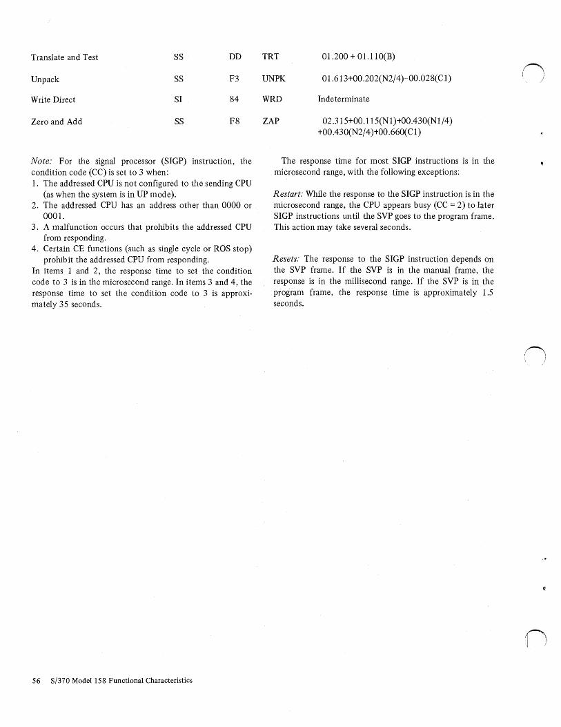
Translate and Test SS DD
Unpack SS F3
Write Direct SI 84
Zero and Add SS F8
Note: For the signal processor (SIGP) instruction, the condition code (CC) is set to 3 when: 1. The addressed CPU is not configured to the sending CPU
(as when the system is in UP mode). 2. The addressed CPU has an address other than 0000 or
0001. 3. A malfunction occurs that prohibits the addressed CPU
from responding. 4. Certain CE functions (such as single cycle or ROS stop)
prohibit the addressed CPU from responding. In items 1 and 2, the response time to set the condition code to 3 is in the microsecond range. In items 3 and 4, the response time to set the condition code to 3 is approximately 35 seconds.
56 S/370 Model 158 Functional Characteristics
TRT 01.200 + 01.1 lO(B)
UNPK 01.613+00.202(N2/4)-00.028(Cl)
WRD Indeterminate
ZAP 02.315+00.115(N 1)+00.430(Nl /4) +00.430(N2/ 4 )+00.660(C1)
The response time for most SIGP instructions is in the microsecond range, with the following exceptions:
Restart: While the response to the SIGP instruction is in the microsecond range, the CPU appears busy (CC 2) to later SIGP instructions until the SVP goes to the program frame. This action may take several seconds.
Resets: The response to the SIGP instruction depends on the SVP frame. If the SVP is in the manual frame, the response is in the millisecond range. If the SVP is in the program frame, the response time is approximately 1.5 seconds.
()
n ;

u
i I u
If the term you are seeking does not appear in this glossary, refer to A Data Processing Glossary, GC20-1699.
Address: An identification of a storage location or an 1/0 device.
Address Compare: A technique to stop the CPU at a specific address.
Address Modification: The process of changing the address part of a machine instruction via coded instructions.
Address Translation: The process of changing the address of an item of data or an instruction from its virtual address to its real storage address.
Alphameric: Pertaining to a character set that contains letters, digits, and special characters.
Attention Identifier (AID): A character that is set by the console in display mode when the operator presses ENTER or CANCEL, or detects a field with the light pen.
Attribute Character: A character that describes the characteristics of the data field that follows it.
Basic Control (BC) Mode: A mode in which the features of a System/360 computing system and additional System/ 370 features, such as new machine instructions, are operational on a System/370 computing system.
CCW: Channel command word.
Control Registers: A set of registers used for operating system control of relocation, priority interruption, program event recording, error recovery, and masking operations.
CPU: Central processing unit.
CRT: Cathode ray tube.
CSW: Channel status word.
CTCA: Channel-to-channel adapter.
Cursor Symbol: A short line (underscore) displayed on the CRT to indicate where the next character entered will be positioned.
Appendix C. Glossary and Abbreviations
DIDOCS: Device independent display operator console support.
DOS/VS: Disk operating system/virtual storage.
Dynamic Address Translation (DAT): (I) The change of a virtual storage address to . a real storage address during execution of an instruction. (2) A hardware feature that performs the translation.
EBCDIC: Extended binary-coded decimal interchange code.
EPO: Emergency power off.
Extended Control (EC) Mode: A mode in which all the features of a System/370 computing system, including dynamic address translation, are operational.
Hardstop: Faulty machine condition in which CPU ceases operation.
Hex: Denoted in the hexadecimal (base 16) number system.
HMS: Hierarchical monitoring system.
JAR: Instruction address register.
IMPL: Initial microprogram load.
Initialize: To set counters, switches, address, etc., to zero or other starting values at the beginning of, or at prescribed points in, a computer program.
IPL: Initial program load.
!SC: Integrated storage controls.
K: I ,024 bytes of storage capacity.
LCL: Limited channel logout.
MCS: Multiple console support.
MP: Multiprocessor or the multiprocessor mode of operation.
Offline: Pertaining to resources with which the central processing unit has no direct communication or control.
Appendix C 57

OLT(S)EP: Online test executive program (standalone).
Online: Pertaining to resources with which the central processing unit has direct communication or control.
OS/VS: Operating system/virtual storage.
Page: (1) A fixed-length block of instructions, data, or both, that can be transferred between real storage and external page storage. (2) To transfer instructions, data, or both, between real storage and external page storage.
Page Table: A table that indicates whether a page is in real storage, and correlates virtual addresses with real storage addresses.
PER: Program event recording.
PFK: Program function key.
PSW: Program status word.
PTLB: Purge translation lookaside buffer.
RAS: Reliability and serviceability.
RCS: Reloadable control storage.
Real Address: The address of a location in real storage.
SAR: Storage address register.
SCU: Storage control unit.
Segment: A continuous 64K area of virtual storage, which is. allocated to a job or system task.
58 S/370 Model 158 Functional Characteristics
Segment Table: A table used in dynamic address translation to contro.._ user access to virtual storage segments. Each entry indicates the length, location, and availability of a corresponding page table.
SF: Start field.
Soft Stop: Stop condition in which CPU clock continues.
TOD: Time-of-day.
UCW: Unit control word.
UP: In an MP system, the uniprocessor mode of operation.
UPS: Uninterruptible power system.
Virtual Address: An address that refers to virtual storage and must, therefore, ·be. translated into a real storage address when it is used.
Wait State: The state of the system when no instructions are being processed, but the system is not fully stopped. The system can accept I/O and external interruptions, and can be put through the IPL procedure.
Word: Predetermined group of bytes whose address is the first byte-address, located in storage by boundary limits; halfword= two bytes, location divisible by 2; fullword four bytes, location divisible by 4; doubleword = eight bytes, location divisible by 8.
U'rite: To transfer data from main storage to an I/O device.
.n I j
() I

u
' U· 1
address logical 5 real 35 translation, dynamic 35 virtual 5
addressing, floating storage 41 alert, malfunction 41 alphameric
characters 44 keys 15
allocation storage 11 switches 41
alter/display frame 22 array, index 10 ASCII bit 5 attention identifier (AID) 25 attention indicators 24 attribute character 25 auto lock 25
basic control (BC) mode 5 bezel indicators 18 buffer
console 13 .1 storage 10 translation lookaside 11
cancel key 1 7 capacities, storage 5 cartridge, ribbon 24 cathode ray tube 13 channel
operations 11 options (see configurator) retry 35 -to-channel adapter (CTCA) 36
characters attention identifier (AID) 25 attribute 15 EBCDIC 44 special 44
check control 20 clock comparator 35 command retry 35 commands, console
display mode 27 printer-keyboard mode 32
compatibility OS/DOS 36 1401/1440/1460 and 1410/7010 36 7070/7074 36
components 5 configuration
control panel 41 frame 18 restrictions 41 valid indicators 41
configurator 6
considerations, display mode 13 console
buffer 13.1 commands 27, 32 display 16 error 18 files 13 functions 13 IMPL pushbutton 14 keyboard 15 modes 13 operator functions, printer 24 support (DIDOCS) 13
control panel 14 controls
integrated storage 36 manual 43 printer 24
CPU error checking 9 instruction fetch 9 instruction retry 9 usage meter 14
CRT operation 13 cursor controls 13 .1
data fields 13 .1 data flow, conceptual 12 description, system 5 designator 27 DIDOCS 13 direct control J6 display
considerations 13.1 console 16 format 14 frames 18 mode 13
dynamic address translation 35
EC mode 5 emergency power-off controls 36 emergency pull 14 emulation 36 end-of-forms indicator 24 enter
configuration pushbutton 41 key 17
entry area 22 error checking 9 extended-precision floating-point 36
facilities 35 features 35 field
definition 13 high intensity 14, 26 light pen detectable 14, 26 nondetectable 14, 26
Index
Index 59

field (continued)
nondisplay 14, 26 -oriented cursor controls 15 protected 14, 26 tagged 14, 25 unprotected 14, 26
files , console 13 floating storage addressing 41 formatted display 14 forms specifications 24 frames
alter/display 22 configuration 18 manual 18 program 21
functions, console 13
glossary 56
hardstop mode 5 hierarchical monitoring system (HMS) 23 high intensity field 14, 26
IMPL pushbutton 14 index array 10 indicators
attention 24 bezel 18 console check 18 control panel 14 end-of-forms 24 input inhibited 21 ISC IMPL check 18 master check 18 message status 22 power check 15 remote 15 sequence 18 system available 21 system status 21 test 21 wait 21
indirect data addressing instruction
fetch 9 line 22 retry 9 set, universal 35 times 45
11
integrated storage controls (ISC) 37 .1 intensity controls 18 interprocessor communications 40 interrupt key 16 interruptions 31 I/0 allocation switches 41 ISC 37.1
keyboard console 15 reset 17
keys alphameric 15 cursor control 15 function 16
lamp test pushbutton 15 light pen 13
60 S/370 Model 158 Functional Characteristics
load 19 local storagf\ 10 logical addrc:ss 5
machine-check interruptions 9 main storage 5 , 10 malfunction alert 41 manual
controls 43 frame 8 indicator 21
messages console 21 recording of 13
mode console 13 display 25 printer-keyboard 32 select 16 system 5
modified data transfer 25 multiprocessing 5, 39, 46
new line 15, 23 nondetectable field 14, 26 nondisplay data 14, 26
operating mode, console 13 operations, channel 11 optional features 36 order sequences 29 OS/DOS compatibility 36
panel, operator control 14 pen, light/ selector 13 positioning, cursor 15 power-check indicator 15 power-off 14 power-on 14 power warning 37 prefixing 40 printer, console 24 printer-keyboard mode 32 program event recording (PER) 12
•program frame 21 program function keys (PFK) 22 program reset 10 protected field 25 PSW bit setting
DAT 35 EC mode 35 PER 11
pushbutton enter configuration 41 IMPL 14 lamp configuration 41 lamp test 15 power-off 14 power-on 14 remote 15
reference and change recording 11 reloadable control storage (RCS) 10 remote clock indicator 43 remote/local clock switch 43
/j

I U' I
remote support facility (RSF) 5 resets 10 restrictions, configuration 41 retry
channel 35 command 35 instruction 9
security key 18 select, mode 16 selector pen detection 25 sense byte 31, 34 sequence lights 18 staging adapter for ISC 38 standard facilities 35 status byte 30, 33 storage
allocation 11 allocation switches 41 buffer 10 controls, integrated 36 floating 41 local 10 main 10 options (see configurator) reloadable control 10 shared 41 virtual 11
store status facility 12 subchannels (see configurator) switches
emergency pull 14 1/0 allocation 41 remote/local clock 15 storage allocation 41 system mode 41 TOD clock 14
system control panel features 43 system mask changes 12 system status 12
tagged field 25 test indicator 21 timer, CPU 35 timing facilities 9 TOD clock
switch 14 synchronization 41
translation lookaside buffer (TLB) 11 two·channel switch 38
valid configuration indicator 41 virtual address 5 virtual machine assist 36 virtual storage 5, 11
wait indicator 21 warning line 22 write control character (WCC) 25
1401/1440/1460 and 1410/7010 compatibility 36 305 6 Remote System Console 13 3213 Console Printer 13, 24 3277 Display Station 13 3330 Disk Storage 38 3340 Disk Storage 38 3830 Storage Control 38 3850 Mass Storage System 38 7070/7074 compatibility 36
•'
Index 61

GA22-7011-4
IIIBOO ®
International Business Machines Corporation Data Processing Division 1133 Westchester Avenue, White Plains, New York 10604 (U.S.A. only)
IBM World Trade Corporation 821 United Nations Plaza, New York, New York 10017 (International)
OJ s Cf) -< VJ ..... Cl)
3 ........ w -..J 0 s 0 a. ~
(J".I 00 ,, i:: :J (") ..... a· :J ~ (') :r DJ ""'! DJ (")
rf~ 0 VJ
,, Ci)
2 ? Cf) ........ w -..J 0 6
'.4' 5· ..... CD a. 5· c i:n ~
Cl )> N N ., ..:.... 0 ...... .;:.
In.·.' , I

it;
(") c: ... Q ii 0 a: )>
0 :J IC
I '5' (!)
I I I I I I I I I I I I I I I I I I I I I I I I I I I I I I
IBM System/370 Model 158 Functional Characteristics
Order No. GA22-70114
This manual is part of a library that serves as a reference source for systems analysts, programmers, and operators of IBM systems. This form may be used to communicate your views about this publication. They will be sent to the author's department for whatever review and action, if any, is deemed appropriate.
IBM shall have the nonexclusive right, in its discretion, to use and distribute all submitted information, in any form, for any and all purposes, without obligation of any kind to the submitter. Your interest is appreciated.
Note: Copies of IBM publications are not stocked at the location to which this form is addressed. Please direct any requests for copies of publications, or for assistance in using your IBM system, to your IBM representative or to the IBM branch office serving your locality.
Possible topics for comment are:
Clarity Accuracy Completeness Organization Coding Retrieval Legibility
If you wish a reply, give your name and mailing address:
What is your occupation?------------------------------
Number of latest Newsletter associated with this publication:-----------------
Thank you for your cooperation. No postage stamp necessary if mailed in the U.S.A. (Elsewhere, an IBM office or representative will be happy to forward your comments.)

GA22-7011-4
Reader's Comment Form
Fold
Business Reply Mail No postage stamp necessary if mailed in U.S.A.
Fold
11rn~ (!)
Postage will be paid by:
International Business Machines Corporation Department 898 P.O. Box 390 Poughkeepsie, New York 12602
International Business Machines Corporation Data Processing Division 1133 Westchester Avenue, White Plains, New York 10604 (U.S.A. only)
IBM World Trade Corporation 821 United Nations Plaza. New York, New York 10017 (International)
Fold
Fold
,, 0 a: )>
0 :I
(C
I I I I I I I I r I
- - -- -I
FIRST CLASS PERMIT NO. 419
POUGHKEEPSIE, N.Y.
I I I I I I I I I I I I
I I I I
------1 I I I I
CJ ~ U) < VI ...+ ('I)
3 -w -...J 0
~ 0 a. ~
CJ1 00 .,, c: ::J (")
!:!'. 0 ::J ~ (') ;:s-!l) ~ !l)
0 ...+
.(\ ('I) ~ u;· lj i ...+ c;· VI .,, ro z ? U) -w -...J 0 6 ......
"'C :::!. ::J ...+ ('I)
a. ::J
c en ?>
G> L )> N N ..!..J , I
0 } ......
~