i mcuez mmds0508 target user’s manual€¦ · mcuez mmds0508 target user’s ... 2.4 mcuez status...
TRANSCRIPT

F
ree
sca
le S
em
ico
nd
uc
tor,
I
Freescale Semiconductor, Inc.n
c..
.
MCUEZMMDS0508/DFEBRUARY 1998
MCUez MMDS0508 TARGET
USER’S MANUAL
© Copyright 1998 MOTOROLA and HIWARE AG; All Rights Reserved
For More Information On This Product,
Go to: www.freescale.com
torolatements out ofentalantiesplied
hat theatentipment
ay betorola’s
ftware
rough
F
ree
sca
le S
em
ico
nd
uc
tor,
I
Freescale Semiconductor, Inc.n
c..
.
Important Notice to Users
While every effort has been made to ensure the accuracy of all information in this document, Moassumes no liability to any party for any loss or damage caused by errors or omissions or by staresulting form negligence, accident, or any other cause. Motorola further assumes no liability arisingthe application or use of any information, product, or system described herein; nor any liability for incidor consequential damages arising from the use of this document. Motorola disclaims alll warrregarding the information contained herein, whether expressed, implied, or statutory, including imwarranties of merchantability or fitness for a particular purpose. Motorola makes no representation tinterconnection of products in the manner described herein will not infringe on existing or future prights, nor do the descriptions contained herein imply the granting or license to make, use, or sell equconstructed in accordance with this description.
Information contained in this document applies to REVision (1) MCUez.
The computer program contains material copyrighted by Motorola Inc., first published 1997, and mused only under a license such as the License For Computer Programs (Article 14) contained in MoTerms and Conditions of Sale, Rev. 1/79.
Trademarks
This document includes these trademarks:
MCUez is a trademark of Motorola Inc.EXORciser is a trademark of Motorola Inc.
The MCUez development, emulation, and debugging application is based on Hi-Wave, a sotechnology developed by HIWARE. Hi-Wave is a registed trademark of HIWARE AG.
AIX, IBM, and PowerPC are trademarks of International Business Machines Corporation.SPARC is a trademark of SPARC International, Inc.Sun and SunOS are trademarks of Sun Microsystems, Inc.UNIX is a trademark of Novell, Inc., in the United States and other countries, licensed exclusively thX/Open Company, Ltd.X Window System is a trademark of Massachusetts Institute of Technology.
For More Information On This Product,
Go to: www.freescale.com

-1
. 2-1. . . 2-1
. 2- . . 2-. . 2-3
. 2-4
. . 2 . . . . . . 2- .. . . 2-6. . 2-8 . .
. . 2-
.
. 2-1. . . . 2
F
ree
sca
le S
em
ico
nd
uc
tor,
I
Freescale Semiconductor, Inc.n
c..
.
CONTENTS
CHAPTER 1 INTRODUCTION
1.1 INTRODUCTION . . . . . . . . . . . . . . . . . . . . . . . . . . . . . . . . . . . . . . . . . . . . . . . . . . . . . . . . . . . 1-1
1.2 DEFINITIONS, ACRONYMS AND ABBREVIATIONS . . . . . . . . . . . . . . . . . . . . . . . . . . . . 1
CHAPTER 2 MMDS0508 TARGET COMPONENT
2.1 INTRODUCTION . . . . . . . . . . . . . . . . . . . . . . . . . . . . . . . . . . . . . . . . . . . . . . . . . . . . . . . . . . . 2-1
2.2 TARGET/SYSTEM INTERFACE . . . . . . . . . . . . . . . . . . . . . . . . . . . . . . . . . . . . . . . . . . . . .2.2.1 Hardware Connection . . . . . . . . . . . . . . . . . . . . . . . . . . . . . . . . . . . . . . . . . . . . . . . . . . . 2-12.2.2 Loading The MMDS0508 Target. . . . . . . . . . . . . . . . . . . . . . . . . . . . . . . . . . . . . . . . . .
2.3 CONFIGURATION DIALOG. . . . . . . . . . . . . . . . . . . . . . . . . . . . . . . . . . . . . . . . . . . . . . . . .32.3.1 Communication Configuration . . . . . . . . . . . . . . . . . . . . . . . . . . . . . . . . . . . . . . . . . . .32.3.2 Communication Device Specification Dialog . . . . . . . . . . . . . . . . . . . . . . . . . . . . . . . . 2.3.3 Data Format . . . . . . . . . . . . . . . . . . . . . . . . . . . . . . . . . . . . . . . . . . . . . . . . . . . . . . . . . . . . 2-4
2.4 MCUEZ STATUS BAR FOR THE MMDS . . . . . . . . . . . . . . . . . . . . . . . . . . . . . . . . . . . . . .
2.5 MMDS0508 MENU . . . . . . . . . . . . . . . . . . . . . . . . . . . . . . . . . . . . . . . . . . . . . . . . . . . . . . . . . 2-42.5.1 MMDS0508 Menu Entries. . . . . . . . . . . . . . . . . . . . . . . . . . . . . . . . . . . . . . . . . . . . . . .-5
2.5.1.1 Communication . . . . . . . . . . . . . . . . . . . . . . . . . . . . . . . . . . . . . . . . . . . . . . . . . . .. 2-52.5.1.1.1 Baud Rate . . . . . . . . . . . . . . . . . . . . . . . . . . . . . . . . . . . . . . . . . . . . . . . . . . . 2-62.5.1.1.2 Show Protocol . . . . . . . . . . . . . . . . . . . . . . . . . . . . . . . . . . . . . . . . . . . . . . . .6
2.5.1.2 Memory Map . . . . . . . . . . . . . . . . . . . . . . . . . . . . . . . . . . . . . . . . . . . . . . . . . . . . . . 2-62.5.1.2.1 Configuration . . . . . . . . . . . . . . . . . . . . . . . . . . . . . . . . . . . . . . . . . . . . . . . . . 2-62.5.1.2.2 About Personality (.MEM) Files . . . . . . . . . . . . . . . . . . . . . . . . . . . . . . . . . . .2.5.1.2.3 Dual-Port RAM . . . . . . . . . . . . . . . . . . . . . . . . . . . . . . . . . . . . . . . . . . . . . . . 2.5.1.2.4 Memory . . . . . . . . . . . . . . . . . . . . . . . . . . . . . . . . . . . . . . . . . . . . . . . . . . . . . 2-9
2.5.1.3 Emul Signals . . . . . . . . . . . . . . . . . . . . . . . . . . . . . . . . . . . . . . . . . . . . . . . . . . . . . . . 2-92.5.1.3.1 MCU Clock . . . . . . . . . . . . . . . . . . . . . . . . . . . . . . . . . . . . . . . . . . . . . . . . . . 92.5.1.3.2 Reset . . . . . . . . . . . . . . . . . . . . . . . . . . . . . . . . . . . . . . . . . . . . . . . . . . . . . . . . 2-10
2.5.1.4 Bus Trace . . . . . . . . . . . . . . . . . . . . . . . . . . . . . . . . . . . . . . . . . . . . . . . . . . . . . . . . . 2-10
2.6 DEFAULT TARGET SETUP . . . . . . . . . . . . . . . . . . . . . . . . . . . . . . . . . . . . . . . . . . . . . . . . 02.6.1 Motorola ESL Parameters . . . . . . . . . . . . . . . . . . . . . . . . . . . . . . . . . . . . . . . . . . . . . . 2-10
2.6.1.1 COMDEV. . . . . . . . . . . . . . . . . . . . . . . . . . . . . . . . . . . . . . . . . . . . . . . . . . . . . . . .. 2-102.6.1.2 BAUDRATE. . . . . . . . . . . . . . . . . . . . . . . . . . . . . . . . . . . . . . . . . . . . . . . . . . . . . . 2-112.6.1.3 SHOWPROT . . . . . . . . . . . . . . . . . . . . . . . . . . . . . . . . . . . . . . . . . . . . . . . . . . . . .-11
MCUEZEVS0508/D iii For More Information On This Product,
Go to: www.freescale.com

. 3-1
.
.
. 3-9
-13
3-1
18
. 4
. .
. 4-7
-15
F
ree
sca
le S
em
ico
nd
uc
tor,
I
Freescale Semiconductor, Inc.n
c..
.
CHAPTER 3 BUS ANALYZER
3.1 INTRODUCTION . . . . . . . . . . . . . . . . . . . . . . . . . . . . . . . . . . . . . . . . . . . . . . . . . . . . . . . . . . . 3-13.1.1 Trace Modes. . . . . . . . . . . . . . . . . . . . . . . . . . . . . . . . . . . . . . . . . . . . . . . . . . . . . . . . . . . . 3-13.1.2 Trace Buffer . . . . . . . . . . . . . . . . . . . . . . . . . . . . . . . . . . . . . . . . . . . . . . . . . . . . . . . . . . . . 3-13.1.3 Textual Or Graphical . . . . . . . . . . . . . . . . . . . . . . . . . . . . . . . . . . . . . . . . . . . . . . . . . . . . . 3-1
3.2 USING THE BUS ANALYZER . . . . . . . . . . . . . . . . . . . . . . . . . . . . . . . . . . . . . . . . . . . . . . .3.2.1 Trigger Setup . . . . . . . . . . . . . . . . . . . . . . . . . . . . . . . . . . . . . . . . . . . . . . . . . . . . . . . . . . . 3-33.2.2 Sequencer Setup . . . . . . . . . . . . . . . . . . . . . . . . . . . . . . . . . . . . . . . . . . . . . . . . . . . . . . . . . 3-43.2.3 Time Tag Clock Setup . . . . . . . . . . . . . . . . . . . . . . . . . . . . . . . . . . . . . . . . . . . . . . . . . . . 3-7
3.3 COLLECTING DATA. . . . . . . . . . . . . . . . . . . . . . . . . . . . . . . . . . . . . . . . . . . . . . . . . . . . . . . . 3-83.3.1 Arming The Analyzer . . . . . . . . . . . . . . . . . . . . . . . . . . . . . . . . . . . . . . . . . . . . . . . . . .. . 3-83.3.2 Disarming The Analyzer . . . . . . . . . . . . . . . . . . . . . . . . . . . . . . . . . . . . . . . . . . . . . . . . . 3-83.3.3 Start Emulation . . . . . . . . . . . . . . . . . . . . . . . . . . . . . . . . . . . . . . . . . . . . . . . . . . . . . . . . . 3-83.3.4 Status Bar . . . . . . . . . . . . . . . . . . . . . . . . . . . . . . . . . . . . . . . . . . . . . . . . . . . . . . . . . . . . . . 3-83.3.5 Halt Data Collection. . . . . . . . . . . . . . . . . . . . . . . . . . . . . . . . . . . . . . . . . . . . . . . . . . . . . . 3-93.3.6 Halt Emulation . . . . . . . . . . . . . . . . . . . . . . . . . . . . . . . . . . . . . . . . . . . . . . . . . . . . . . . . . . 3-93.3.7 Recording Bus Data . . . . . . . . . . . . . . . . . . . . . . . . . . . . . . . . . . . . . . . . . . . . . . . . . . . . . . 3-93.3.8 Trigger Event . . . . . . . . . . . . . . . . . . . . . . . . . . . . . . . . . . . . . . . . . . . . . . . . . . . . . . . . . . . 3-9
3.4 VIEWING COLLECTED DATA . . . . . . . . . . . . . . . . . . . . . . . . . . . . . . . . . . . . . . . . . . . . . . 3.4.1 Textual Display . . . . . . . . . . . . . . . . . . . . . . . . . . . . . . . . . . . . . . . . . . . . . . . . . . . . . . . . 3-103.4.2 Instructions Only Display . . . . . . . . . . . . . . . . . . . . . . . . . . . . . . . . . . . . . . . . . . . . . . .. 3-113.4.3 Graphical Display . . . . . . . . . . . . . . . . . . . . . . . . . . . . . . . . . . . . . . . . . . . . . . . . . . . . . . 3-113.4.4 Time Mesasuring . . . . . . . . . . . . . . . . . . . . . . . . . . . . . . . . . . . . . . . . . . . . . . . . . . . . . . . 3-133.4.5 ShowLocation . . . . . . . . . . . . . . . . . . . . . . . . . . . . . . . . . . . . . . . . . . . . . . . . . . . . . . . . . 3-13
3.5 ADD / REMOVE ITEMS IN THE TRACE WINDOW . . . . . . . . . . . . . . . . . . . . . . . . . . . . . 3
3.6 SCROLLING THE DISPLAY. . . . . . . . . . . . . . . . . . . . . . . . . . . . . . . . . . . . . . . . . . . . . . . . .43.6.1 Search For A Frame . . . . . . . . . . . . . . . . . . . . . . . . . . . . . . . . . . . . . . . . . . . . . . . . . . .. . 3-143.6.2 Search For Events . . . . . . . . . . . . . . . . . . . . . . . . . . . . . . . . . . . . . . . . . . . . . . . . . . . . . . 3-153.6.3 Next Event . . . . . . . . . . . . . . . . . . . . . . . . . . . . . . . . . . . . . . . . . . . . . . . . . . . . . . . . . . . . 3-163.6.4 Previous Event . . . . . . . . . . . . . . . . . . . . . . . . . . . . . . . . . . . . . . . . . . . . . . . . . . . . . . . . . 3-163.6.5 Search For A Pattern . . . . . . . . . . . . . . . . . . . . . . . . . . . . . . . . . . . . . . . . . . . . . . . . . . . . 3-16
3.7 DUMPING THE BUS ANALYZER DATA TO A FILE . . . . . . . . . . . . . . . . . . . . . . . . . . . . 3-
CHAPTER 4 MMDS COMMANDS
4.1 INTRODUCTION . . . . . . . . . . . . . . . . . . . . . . . . . . . . . . . . . . . . . . . . . . . . . . . . . . . . . . . . . . . 4-1
4.2 BAUD RATE COMMAND. . . . . . . . . . . . . . . . . . . . . . . . . . . . . . . . . . . . . . . . . . . . . . . . . . .-1
4.3 TRIGGER COMMANDS . . . . . . . . . . . . . . . . . . . . . . . . . . . . . . . . . . . . . . . . . . . . . . . . . . . 4-2
4.4 BUS ANALYZER COMMANDS. . . . . . . . . . . . . . . . . . . . . . . . . . . . . . . . . . . . . . . . . . . . . .
4.5 TARGET SIGNAL EMULATION COMMANDS . . . . . . . . . . . . . . . . . . . . . . . . . . . . . . . . . 4
iv MCUEZEVS0508/D For More Information On This Product,
Go to: www.freescale.com

. 4-16
. .
. . 2
. . 2-5. . . .
. . 3-3 . . 3-5 . 3-7. . . 3-12 . 3 .
. . . . 3-1
. 3-18
F
ree
sca
le S
em
ico
nd
uc
tor,
I
Freescale Semiconductor, Inc.n
c..
.
4.6 RESET COMMANDS. . . . . . . . . . . . . . . . . . . . . . . . . . . . . . . . . . . . . . . . . . . . . . . . . . . . . .. 4-15
4.7 PROTOCOL COMMANDS . . . . . . . . . . . . . . . . . . . . . . . . . . . . . . . . . . . . . . . . . . . . . . . . .
FIGURESFigure 2-1. Hardware Connection . . . . . . . . . . . . . . . . . . . . . . . . . . . . . . . . . . . . . . . . . . . . . . . . . . 2-1Figure 2-2. Component Menu . . . . . . . . . . . . . . . . . . . . . . . . . . . . . . . . . . . . . . . . . . . . . . . . . . . . . 2-2Figure 2-3. Replacing The Target Menu . . . . . . . . . . . . . . . . . . . . . . . . . . . . . . . . . . . . . . . . . . . 2-2Figure 2-4. MotoSIL Menu . . . . . . . . . . . . . . . . . . . . . . . . . . . . . . . . . . . . . . . . . . . . . . . . . . . . . . . 2-3Figure 2-5. Communication Device Dialog. . . . . . . . . . . . . . . . . . . . . . . . . . . . . . . . . . . . . . . . .-3Figure 2-6. MCUez Status Bar . . . . . . . . . . . . . . . . . . . . . . . . . . . . . . . . . . . . . . . . . . . . . . . . . . . . 2-4Figure 2-7. MMDS0508 Menu . . . . . . . . . . . . . . . . . . . . . . . . . . . . . . . . . . . . . . . . . . . . . . . . . .. . 2-5Figure 2-8. Communication Device Specification Dialog. . . . . . . . . . . . . . . . . . . . . . . . . . . . . . Figure 2-9. Memory Configuration Dialog . . . . . . . . . . . . . . . . . . . . . . . . . . . . . . . . . . . . . . . . . 2-6Figure 2-10. Configuration Error Dialog. . . . . . . . . . . . . . . . . . . . . . . . . . . . . . . . . . . . . . . . . . . . 2-7Figure 2-11. Open Personality File Dialog . . . . . . . . . . . . . . . . . . . . . . . . . . . . . . . . . . . . . . . . .. 2-7Figure 2-12. Target Signals Dialog . . . . . . . . . . . . . . . . . . . . . . . . . . . . . . . . . . . . . . . . . . . . . . . . . 2-9Figure 3-1. Trace Window . . . . . . . . . . . . . . . . . . . . . . . . . . . . . . . . . . . . . . . . . . . . . . . . . . . . . . . . 3-2Figure 3-2. Bus Analyzer Configuration Dialog . . . . . . . . . . . . . . . . . . . . . . . . . . . . . . . . . . . . . Figure 3-3. Bus Analyzer Configuration Dialog (Sequencer Tab) . . . . . . . . . . . . . . . . . . . . . . .Figure 3-4. Bus Analyzer Configuration Dialog (Time Tag Clock Tab) . . . . . . . . . . . . . . . . . . . .Figure 3-5. Trace Window Elements . . . . . . . . . . . . . . . . . . . . . . . . . . . . . . . . . . . . . . . . . . . . . 3-10Figure 3-6. Trace Window - Graphical Display. . . . . . . . . . . . . . . . . . . . . . . . . . . . . . . . . . . . . .Figure 3-7. Trace Window - Zoom Out . . . . . . . . . . . . . . . . . . . . . . . . . . . . . . . . . . . . . . . . . . . .-12Figure 3-8. Items Configuration Dialog . . . . . . . . . . . . . . . . . . . . . . . . . . . . . . . . . . . . . . . . . . . 3-13Figure 3-9. Item Content Dialog . . . . . . . . . . . . . . . . . . . . . . . . . . . . . . . . . . . . . . . . . . . . . . . . . . 3-14Figure 3-10. Search For Event Or Pattern . . . . . . . . . . . . . . . . . . . . . . . . . . . . . . . . . . . . . . . . .3-14Figure 3-11. Search Frame Dialog. . . . . . . . . . . . . . . . . . . . . . . . . . . . . . . . . . . . . . . . . . . . . . .. . 3-15Figure 3-12. Search Event Specification Dialog . . . . . . . . . . . . . . . . . . . . . . . . . . . . . . . . . . . . 5Figure 3-13. Search For Pattern . . . . . . . . . . . . . . . . . . . . . . . . . . . . . . . . . . . . . . . . . . . . . . . . . . . 3-16Figure 3-14. Dump Bus Analyzer Frames Dialog . . . . . . . . . . . . . . . . . . . . . . . . . . . . . . . . . . . .
MCUEZEVS0508/D v For More Information On This Product,
Go to: www.freescale.com

F
ree
sca
le S
em
ico
nd
uc
tor,
I
Freescale Semiconductor, Inc.n
c..
.
vi MCUEZEVS0508/D For More Information On This Product,
Go to: www.freescale.com

INTRODUCTION
target to theCU
state to
cany the
CPUnning)
al
the
F
ree
sca
le S
em
ico
nd
uc
tor,
I
Freescale Semiconductor, Inc.n
c..
.
CHAPTER 1
INTRODUCTION
1.1 INTRODUCTION
MCUez features target system interfaces that give you the ability to load different components of an embedded system. This manual introduces the interfaces relatedMMDS0508 Modular Development System for the MC68HC05 and MC68HC08 MFamilies.
The MMDS0508 is an emulator system that provides emulation memory and a busanalyzer for MCUs with a CPU05 or CPU08. MCUez uses Motorola’s MMDScommunicate with a target system.
Using the MMDS interface, an external target system based on a Motorola MCUdownload an executable program from the MCUez environment, execute it, and relaresults of the real target system behavior to MCUez.
MCUez fully supervises and monitors the target system’s MCU. It also controls activities such as read and write in internal/external memory (even when the CPU is ruand single-step/run/stop processes.
NOTE
When an external MCU is executing code, the memory statistics are notavailable to the MMDS target component.
1.2 DEFINITIONS, ACRONYMS AND ABBREVIATIONS
DLL Dynamic Link Library: Windows library file used in dynamic linking.
Dynamic Linking Windows process used to link a function call in one module to the actufunction in the library module at run time.
MMDS0508 ServerThe MMDS hardware access library responsible for interfacing acrossRS-232 port to the MMDS0508 station.
Modal Dialog Dialog that requires a response before continuing.
MCU Micro Controller Unit
MCUEZMMDS0508/D 1-1 For More Information On This Product,
Go to: www.freescale.com

INTRODUCTION
F
ree
sca
le S
em
ico
nd
uc
tor,
I
Freescale Semiconductor, Inc.n
c..
.
EM Emulation Module
1-2 MCUEZMMDS0508/D For More Information On This Product,
Go to: www.freescale.com

MMDS0508 TARGET COMPONENT
8 and
to the data to the
F
ree
sca
le S
em
ico
nd
uc
tor,
I
Freescale Semiconductor, Inc.n
c..
.
CHAPTER 2
MMDS0508 TARGET COMPONENT
2.1 INTRODUCTION
This chapter describes how set up communication between MCUez and the MMDS050explains the windows and dialog boxes associated with the process.
2.2 TARGET/SYSTEM INTERFACE
The MMDS0508 box is connected to the RS-232 serial port of your system.
2.2.1 Hardware Connection
Use the serial link cables provided with the MMDS0508 to connect the host computer MMDS0508 box (see the following diagram). The host computer is configured as aterminal, i.e. it sends data on the TxD lead and receives data on the RxD lead (referMMDS0508 hardware manual).
Figure 2-1. Hardware Connection
Host Computer MMDS0508 Box
Serial Link
MCUEZMMDS0508/D 2-1 For More Information On This Product,
Go to: www.freescale.com
MMDS0508 TARGET COMPONENT
MDShe the to the then portils.
F
ree
sca
le S
em
ico
nd
uc
tor,
I
Freescale Semiconductor, Inc.n
c..
.
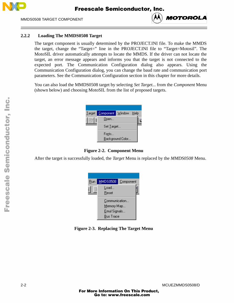
2.2.2 Loading The MMDS0508 Target
The target component is usually determined by the PROJECT.INI file. To make the Mthe target, change the “Target=” line in the PROJECT.INI file to “Target=Motosil”. TMotoSIL driver automatically attempts to locate the MMDS. If the driver can not locatetarget, an error message appears and informs you that the target is not connectedexpected port. The Communication Configuration dialog also appears. UsingCommunication Configuration dialog, you can change the baud rate and communicatioparameters. See the Communication Configuration section in this chapter for more deta
You can also load the MMDS0508 target by selecting Set Target... from the Component Menu(shown below) and choosing MotoSIL from the list of proposed targets.
Figure 2-2. Component Menu
After the target is successfully loaded, the Target Menu is replaced by the MMDS0508 Menu.
Figure 2-3. Replacing The Target Menu
2-2 MCUEZMMDS0508/D For More Information On This Product,
Go to: www.freescale.com

MMDS0508 TARGET COMPONENT
y
serialrrect,
lly. Ifopen.
icated,
F
ree
sca
le S
em
ico
nd
uc
tor,
I
Freescale Semiconductor, Inc.n
c..
.
If the MotoSIL driver does not detect a target, the MotoSIL Menu replaces the Target Menu:
Figure 2-4. MotoSIL Menu
The MMDS0508 Menu will replace the MotoSIL Menu if the MMDS target is successfulllocated during later attempts.
2.3 CONFIGURATION DIALOG
Ensure the parameters on the host computer are correctly configured and that thecommunication device is set correctly. If the configurations and settings are not cocommunication between MCUez and the target is not possible.
2.3.1 Communication Configuration
In a general way, the communication between MCUez and the MMDS is set automaticaMCUez does not detect a target, the Communication Device Specification dialog will This dialog can also be opened selecting the MotoSIL menu and choosing Connect....
2.3.2 Communication Device Specification Dialog
If the host and target are not connected or the communication device is not properly inda dialog box, Communications Device Specification, appears:
Figure 2-5. Communication Device Dialog
MCUEZMMDS0508/D 2-3 For More Information On This Product,
Go to: www.freescale.com

MMDS0508 TARGET COMPONENT
ter the
gs for will beithout
te. Thecations
us bar
ningU-Id),
F
ree
sca
le S
em
ico
nd
uc
tor,
I
Freescale Semiconductor, Inc.n
c..
.
The default device is COM1. To choose another available communication device, endevice name in the Communication Device edit box, scroll for the corresponding Baud Rate,select it, and click Connect.
After the connection with the chosen communication device is established, the settinthat device are saved for later debug sessions. If the connection fails, a message boxdisplayed and a new communication device can be defined. To close the dialog box wattempting a new connection, select Cancel.
NOTE
The communication device and baud rate, which are saved through this dialog,override the environment variables BAUDRATE and COMDEV in thedefault.env file.
2.3.3 Data Format
MCUez uses the data format: 8 data bits, 1 stop bit, no parity, and a variable baud radefault baud rate is 9600 baud unless it has been redefined through the CommuniDevice Specification dialog.
2.4 MCUEZ STATUS BAR FOR THE MMDS
When the MMDS Target Component has been successfully loaded, the MCUez statdisplays specific information:
Figure 2-6. MCUez Status Bar
Displayed from left to right are: the baud rate of serial communication, the MCUez runmode, the BUS analyzer mode, the name of the connected MCU (depending on the MCand the debugger status.
2.5 MMDS0508 MENU
When the MMDS0508 is successfully set as the target, the MMDS0508 menu appears (seeLoading the MMDS0508 Target in this chapter). The MMDS0508 menu contains functionsspecific to the MMDS0508.
Baud Rate
Running Mode
BUS Analyzer Mode
MCU Id
Debugger Status
2-4 MCUEZMMDS0508/D For More Information On This Product,
Go to: www.freescale.com

MMDS0508 TARGET COMPONENT
bled
s that
at itslectostls, the
F
ree
sca
le S
em
ico
nd
uc
tor,
I
Freescale Semiconductor, Inc.n
c..
.
2.5.1 MMDS0508 Menu Entries
The functions in the MMDS0508 menu are specific to the MMDS0508 and are only availawith this emulator component. To use an item in the MMDS0508 menu, select the menu anchoose the desired function:
Figure 2-7. MMDS0508 Menu
The Communication..., Memory Map..., Emul Signals..., and Bus Trace functions are part ofthe MMDS0508 Motorola Modular Development System and are supported by librarieconsist of dialog boxes and routines that interface with the debugger and hardware.
2.5.1.1 Communication
The system operates most efficiently when the baud rate of the host computer ismaximum. To display the Communication Device Specification dialog, seCommunication... from the MMDS0508 menu. Select the maximum baud rate your hsupports or 115200, the maximum baud rate currently supported. If communication faiprevious baud rate is used.
Figure 2-8. Communication Device Specification Dialog
MCUEZMMDS0508/D 2-5 For More Information On This Product,
Go to: www.freescale.com

MMDS0508 TARGET COMPONENT
ter. The
inethe inugging
n
ticallye
ing
F
ree
sca
le S
em
ico
nd
uc
tor,
I
Freescale Semiconductor, Inc.n
c..
.
2.8.0.0.1 Baud Rate
The maximum baud rate depends on the speed and the interrupt load of the host compudefault value is 9600.
2.8.0.0.2 Show Protocol
Check the Show Protocol box to display the communication protocol in the Command lComponent. Display from the communication protocol results in superfluous output in the Command Line component. This feature should only be used for advanced debissues.
2.5.1.2 Memory Map
Choose Memory Map... from the MMDS0508 menu to open the Memory Configuratiodialog:
Figure 2-9. Memory Configuration Dialog
2.9.0.0.1 Configuration
Configuration contains the target’s memory setup. The target memory setup is automaloaded if the Auto select according to MCU-Id box is checked. MCUez identifies and sets thmemory map through the MCU-Id. To open another configuration, select the Load... button.To save modifications to the current configuration, select the Save... button.
2.9.0.0.2 About Personality (.MEM) Files
To work properly, the Motosil target has to load the personality file (.MEM file) matchwith the connected Emulation Module (EM).
2-6 MCUEZMMDS0508/D For More Information On This Product,
Go to: www.freescale.com
MMDS0508 TARGET COMPONENT
wo
is
evice
F
ree
sca
le S
em
ico
nd
uc
tor,
I
Freescale Semiconductor, Inc.n
c..
.
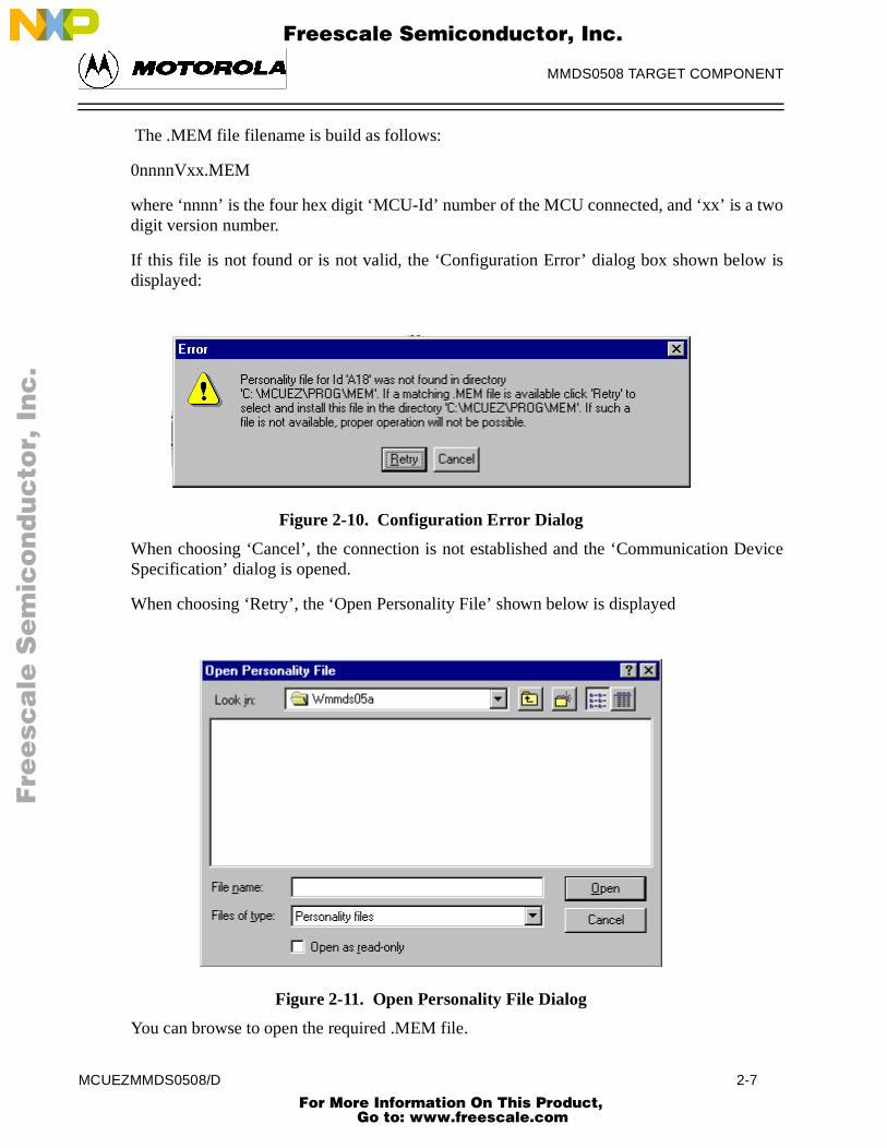
The .MEM file filename is build as follows:
0nnnnVxx.MEM
where ‘nnnn’ is the four hex digit ‘MCU-Id’ number of the MCU connected, and ‘xx’ is a tdigit version number.
If this file is not found or is not valid, the ‘Configuration Error’ dialog box shown belowdisplayed:
Figure 2-10. Configuration Error Dialog
When choosing ‘Cancel’, the connection is not established and the ‘Communication DSpecification’ dialog is opened.
When choosing ‘Retry’, the ‘Open Personality File’ shown below is displayed
Figure 2-11. Open Personality File Dialog
You can browse to open the required .MEM file.
MCUEZMMDS0508/D 2-7 For More Information On This Product,
Go to: www.freescale.com

MMDS0508 TARGET COMPONENT
en the
with
.
”
eROM theor
F
ree
sca
le S
em
ico
nd
uc
tor,
I
Freescale Semiconductor, Inc.n
c..
.
If the .MEM file that you selected is not valid, an error message box pops up, and th‘Configuration Error’ dialog box is opened again.
If the selected .MEM file is valid, it is loaded and copied into the \PROG\MEM directory ‘V00’ as version number (e.g. 00A18V00.MEM).
NOTE
The ‘Memory Configuration’ dialog displays the current memory map.
When starting MCUez:
If the ‘Auto Select according MCU-ID’ check box is checked, the defaultpersonality file matching with the MCU-ID is automatically loaded. If this checkbox is not checked, the previous opened or saved memory map file isautomatically loaded.
The memory configuration can be modified within this ‘Memory Configuration’dialog and saved into a memory configuration file when clicking the ‘SAVE’button .
You can load a different memory configuration file (e.g. that you definedyourself and saved previously) when clicking the ‘LOAD’ button of the‘Memory Configuration’ dialog.
Also Personality files or any memory configuration files can be loaded with theLOADMAP command line command.
2.11.0.0.1 Dual-Port RAM
Dual-Port RAM allows you to specify the base address and enable “Real-Time Memory”
To specify the base address, enter the desired value in the Base Address edit box. To Enablethe “Real-Time Memory”, check the Enable check box. The size of the “Real-Time Memoryis frozen to 1 kilobyte.
NOTE
Periodical update mode in the Data or Memory component is only possible forvariables or memory positions located in the Dual Port RAM area.
2.11.0.0.2 Memory
Memory allows you to specify the “Real-Time Memory”. The MMDS0508 “Real-TimMemory” consists of dual-ported memory that can be assigned to any valid RAM or memory address. While the MMDS0508 is running, MCUez can display and modify“Real-Time Memory”. If a portion of the memory overlays internal MCU I/O, RAM, EEPROM, that portion can only be displayed, not monitored.
2-8 MCUEZMMDS0508/D For More Information On This Product,
Go to: www.freescale.com

MMDS0508 TARGET COMPONENT
wn
argeter the
ion.
ase
in
F
ree
sca
le S
em
ico
nd
uc
tor,
I
Freescale Semiconductor, Inc.n
c..
.
2.5.1.3 Emul Signals
Choose Emul Signals... from the MMDS0508 menu to open the Target Signals dialog shobelow:
Figure 2-12. Target Signals Dialog
The MMDS0508 emulator signals can be specified through this dialog. When the TSignals dialog is accessed, the settings are read from the MMDS0508. If you altdisplayed values and select Ok, the values are written to the MMDS0508. If you check Saveand Reload, the configuration is reloaded when the MCUez debugger is started.
Target Signals dialog can also be used to alter the MCU clock and reset signal connect
2.12.0.0.1 MCU Clock
MCU Clock allows you to change the MCU clock if the EM is correctly configured (Plerefer to your EM manual).
2.12.0.0.2 Reset
Reset allows you to control the reset signal connection with the target system.
2.5.1.4 Bus Trace
Select Bus Trace from the MMDS0508 menu to run the Bus Analyzer. See the Using The BusAnalyzer chapter of this document for more details.
2.6 DEFAULT TARGET SETUP
The MMDS target component can be loaded from the Target menu or set as a default target the project.ini file, which should be in the working directory.
Example project.ini file:
MCUEZMMDS0508/D 2-9 For More Information On This Product,
Go to: www.freescale.com

MMDS0508 TARGET COMPONENT
ings
st andtems
F
ree
sca
le S
em
ico
nd
uc
tor,
I
Freescale Semiconductor, Inc.n
c..
.
[DEFAULTS]
Window0=Source 0 0 50 40
Window1=Assembly 50 0 50 40
Window2=Register 50 40 50 30
Window3=Memory 50 70 50 30
Window4=Data 0 40 50 25
Window5=Command 0 65 50 20
Window6=Module 0 85 50 15
Target=Motosil
[Motorola ESL]
COMDEV=COM2
BAUDRATE=57600
SHOWPROT=0
2.6.1 Motorola ESL Parameters
Normally, the Motorola ESL parameters are interactively set during installation. The settare stored in the project.ini file and used in the future debugging sessions.
2.6.1.1 COMDEV
The COMDEV parameter specifies the communication device to be used between the hoMM0508. COM1 is the default communication device for PCs. The default for UNIX sysis /dev/ttya.
For a PC: Any valid communication device (COM1,COM2,etc.).
Example:COMDEV=COM2
For SUN:Any valid communication device (/dev/ttya, etc.).
Example:comdev=/dev/ttyb
2-10 MCUEZMMDS0508/D For More Information On This Product,
Go to: www.freescale.com

MMDS0508 TARGET COMPONENT
preset
or 1 witheLine
F
ree
sca
le S
em
ico
nd
uc
tor,
I
Freescale Semiconductor, Inc.n
c..
.
2.6.1.2 BAUDRATE
BAUDRATE, the rate of serial communication between the target and host systems, isto 9600 bauds and may be overwritten by one of the following baud rates:
1200, 2400, 4800, 9600, 19200, 28800, 38400, 57600, or 115200.
Example:BAUDRAUTE=19200
2.6.1.3 SHOWPROT
SHOWPROT determines the display of the communication protocol. The value is set to 0(1 to show the communication protocol, 0 to hide it) at the first communication attemptthe target. You can check the Show Protocol checkbox in the Communication DevicSpecification dialog if you want to display the communication protocol in a Command window.
MCUEZMMDS0508/D 2-11 For More Information On This Product,
Go to: www.freescale.com

MMDS0508 TARGET COMPONENT
F
ree
sca
le S
em
ico
nd
uc
tor,
I
Freescale Semiconductor, Inc.n
c..
.
2-12 MCUEZMMDS0508/D For More Information On This Product,
Go to: www.freescale.com

BUS ANALYZER
an becutionurring
various certainr, define event.
he Bused intorred in
al and
F
ree
sca
le S
em
ico
nd
uc
tor,
I
Freescale Semiconductor, Inc.n
c..
.
CHAPTER 3
BUS ANALYZER
3.1 INTRODUCTION
Except for the emulation of the target system MCU, the most important feature that coffered by a microcontroller development tool is an instrument to analyze program exeactivities on the target MCU bus. This analysis allows the user to determine what is occin a system without actually affecting it.
NOTE
The Bus analyzer in the MMDS0508 shows the logical state of the MCU bus. Itdoes not show signal hold and setup times.
3.1.1 Trace Modes
To gather pertinent bus data, the Bus analyzer can be operated in different modes. Thetrace modes of the Bus analyzer make it possible to choose the actions to take when apattern (event) or sequence of patterns appears on the bus. To trigger the Bus analyzethe desired bus state(s) as terms and select the desired sequence of terms as a trigger
3.1.2 Trace Buffer
The trace buffer contains 8,192 entries, or frames, each of which stores 96 bits. When tanalyzer is activated and the emulator is running, a frame of the selected type is strobthe trace buffer for each bus cycle. When the event(s) to trigger the analyzer has occuthe specified sequence, only the specified number of additional frames are stored.
3.1.3 Textual Or Graphical
The Bus analyzer can display the data either textually or graphically. Use the horizontvertical scroll bars, as in other Windows applications, to move around the display.
MCUEZMMDS0508/D 3-1 For More Information On This Product,
Go to: www.freescale.com

BUS ANALYZER
rol thecalledded by
eps are,gram),
essc name
F
ree
sca
le S
em
ico
nd
uc
tor,
I
Freescale Semiconductor, Inc.n
c..
.
3.2 USING THE BUS ANALYZER
The Bus analyzer functions like any MCUez component, and has its own menu to contfeatures of the MMDS0508 Bus analyzer hardware. The Bus Analyzer window is also Trace. Indeed the Bus Analyzer matches with the Trace Component and can also be loachoosing Open... Trace from the Component menu. Choose the MMDS0508 menu and selectBus Trace to open the Trace window or the Bus Analyzer.
From the user's perspective, using the Bus analyzer requires three steps. These stdefining the data collection parameters, collecting the desired bus data (running the proand viewing the collected data.
Figure 3-1. Trace Window
The Bus analyzer contains setup pages for these functions:
• Triggers
• Pattern
• Sequencer
• Time Tag Clock
These setup pages are shown as tabs in the Bus Analyzer Configuration dialog box.
The Bus Analyzer Configuration dialog box allows you to define symbolic names for addrvalues. When you change setup pages in the dialog box, the address and symbolivalues must match. If there is an inconsistency, you will be prompted to:
• Use the address and remove the symbol.
3-2 MCUEZMMDS0508/D For More Information On This Product,
Go to: www.freescale.com
BUS ANALYZER
e thesewn
, you
ges, yougether
dress oronding
an
F
ree
sca
le S
em
ico
nd
uc
tor,
I
Freescale Semiconductor, Inc.n
c..
.
• Replace the address with the symbol address.
• Fix the inconsistency by returning to the dialog box and clicking the symbol button.
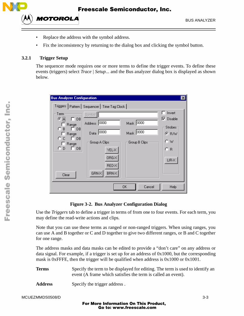
3.2.1 Trigger Setup
The sequencer mode requires one or more terms to define the trigger events. To definevents (triggers) select Trace | Setup... and the Bus analyzer dialog box is displayed as shobelow.
Figure 3-2. Bus Analyzer Configuration Dialog
Use the Triggers tab to define a trigger in terms of from one to four events. For each termmay define the read-write actions and clips.
Note that you can use these terms as ranged or non-ranged triggers. When using rancan use A and B together or C and D together to give two different ranges, or B and C tofor one range.
The address masks and data masks can be edited to provide a “don’t care” on any addata signal. For example, if a trigger is set up for an address of 0x1000, but the correspmask is 0xFFFE, then the trigger will be qualified when address is 0x1000 or 0x1001.
Terms Specify the term to be displayed for editing. The term is used to identifyevent (A frame which satisfies the term is called an event).
Address Specify the trigger address .
MCUEZMMDS0508/D 3-3 For More Information On This Product,
Go to: www.freescale.com

BUS ANALYZER
l of thetes of
s to
p untilen the
and thehas andition
hich the be theignored
F
ree
sca
le S
em
ico
nd
uc
tor,
I
Freescale Semiconductor, Inc.n
c..
.
Data Specify the trigger data .
Strobes Specify the state of R/W on which to trigger.
Group A Clips Toggle to specify each logic clip as High, Low or Don’t Care.
The clips buttons show the Group A logic clips with their respective colors.
Logic clips are used to trace the signals in your target system as it runs under the controsoftware. When a trigger occurs, a breakpoint is provided that shows you the stasignificant logic signals before, at, and after the breakpoint.
Invert To specify that a term, previously defined as triggered within a range, ibe triggered outside that range, select Invert.
Disable To disable the trigger for a specific term, select Disable.
Clear To clear all the changes on the Bus Analyzer Configuration press Clear.
3.2.2 Sequencer Setup
To choose one of the recording modes, select the menu item Trace | Setup... which pops up theBus Analyzer Configuration dialog box and then click on the tab labelled Sequencer (seefigure below).
In Non-triggered modes (continuous and counted modes), the collection does not stothe analyzer is terminated (Analyze stpos when execution of the application stops or whbus analyzer is disarmed).
In triggered modes, the defined terms are used to track the occurrence of events, collection of data is stopped based on some combination of the events. Each term associated Pre Event count which will count events for that term. The sequencer conwill use that term when the count is reached.
An event is a pattern of bus signals (which can include addresses and data values) to wanalyzer is connected by logic clips and miscellaneous MCU signals. An event can alsonegation of a defined pattern. Each signal can be defined as asserted, negated, or (don't care).
3-4 MCUEZMMDS0508/D For More Information On This Product,
Go to: www.freescale.com

BUS ANALYZER
he
ever
les.
tion
F
ree
sca
le S
em
ico
nd
uc
tor,
I
Freescale Semiconductor, Inc.n
c..
.
Figure 3-3. Bus Analyzer Configuration Dialog (Sequencer Tab)
Click on one of the nine option buttons to select the recording mode:
Non-Triggered Modes:
Continuous: All Cycles Provides a real-time, non-invasive trace of MCU bus activities. TBus analyzer stores all cycles. When used in this way, the Bus analyzer continuously records bus data in the trace buffer whenthe user target system is being emulated. No qualifications for triggering or halting data collection can be defined.
Continuous: Events OnlyStores all events. Events are defined by the terms set up in theTriggers dialog box.
Counted Modes:
Counted: All Cycles Configures the Bus analyzer to record a specified number of cycThe user can trace a specified number of cycles of all types.
Counted: Events Only Stores all events until the specified count is reached, then collecstops.
MCUEZMMDS0508/D 3-5 For More Information On This Product,
Go to: www.freescale.com

BUS ANALYZER
her ed
ts ). ts
hen after
in ains in t
t is
),
f post-
des one t-
was
F
ree
sca
le S
em
ico
nd
uc
tor,
I
Freescale Semiconductor, Inc.n
c..
.
Triggered/Sequential Modes:
Sequential: A + B + C + D
Select this option for the bus analyzer to start recording after eitevent A or B or C or D. Storing data terminates after the specifinumber of post-trigger cycles.
Sequential: A + B -> C + D
Select this option to start the bus analyzer on either of two even(event A or B) followed by either of two other events (event C or DThe sequencer can be simplified to involve fewer than four evenby leaving unused events defined with all signals ignored. Datastorage ends after the specified number of post-trigger cycles.
Sequential: A -> B -> C -> D
Select this option to start the bus analyzer after four events, A tB then C then D, occuring in sequence. Storing data terminates specified number of post-trigger cycles.
Sequential: A -> B -> C, D<-
Select this option to start the bus analyzer on cycles of 3 eventssequence, A then B then C, provided that the fourth event, D remfalse. When the fourth event, D occurs, the sequence starts agawith the first event. This sequence can be used as a three-evensequence by leaving event D defined with all signals ignored. Storing data terminates after specified number of post-trigger cycles.
Nth Event After A+B+C+D
Select this option for the bus analyzer to begin storing data thatmatches event A, event B, event C, and event D, until Nth evenstored. Then the next 4096 cycles are stored. This allows for a maximum of 4096 events to be stored (including the Nth eventfollowed by 4096 cycles.
For all Triggered/Sequential modes, data storage ends after the specified number otrigger cycles.
Counted/Sequential Recording Mode:
Terminal Count/Post Trigger Cycles (1..8191)
Enter a number in the range of 1 to 8191. If one of the counted mowas selected, this number is the count of bus cycles to trace. If of the sequential modes was selected, this is the number of postrigger cycles to trace. If one of the continuous recording modes selected, this value is ignored.
3-6 MCUEZMMDS0508/D For More Information On This Product,
Go to: www.freescale.com
BUS ANALYZER
less
every
Bus
F
ree
sca
le S
em
ico
nd
uc
tor,
I
Freescale Semiconductor, Inc.n
c..
.
Stop the emulator when recording completes
The stop of the collection of bus cycles does not stop the emulation unthis check box is checked. Click on the check box Stop the emulator when recording completes to enable or disable this feature. Then click the OK button to apply your choice and close the dialog box.
NOTE
The terminal count or post trigger cycles are valid only for counted orsequential modes. For a counted mode, this field specifies the number of cyclesto be stored. For a sequential mode, this field specifies the number of cycles to bestored after the trigger sequence occurs.
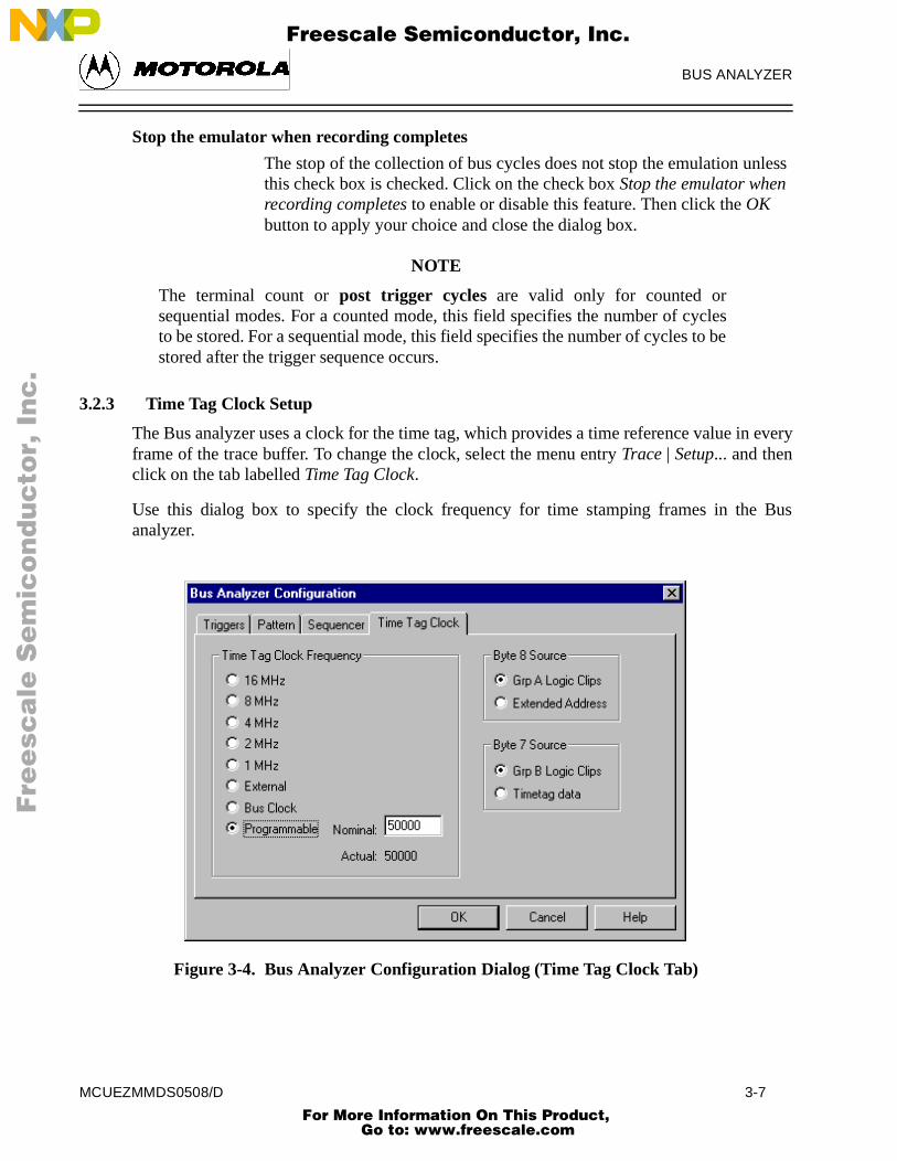
3.2.3 Time Tag Clock Setup
The Bus analyzer uses a clock for the time tag, which provides a time reference value inframe of the trace buffer. To change the clock, select the menu entry Trace | Setup... and thenclick on the tab labelled Time Tag Clock.
Use this dialog box to specify the clock frequency for time stamping frames in theanalyzer.
Figure 3-4. Bus Analyzer Configuration Dialog (Time Tag Clock Tab)
MCUEZMMDS0508/D 3-7 For More Information On This Product,
Go to: www.freescale.com

BUS ANALYZER
ither able re
50,000e
r, theed up
in the
isarm
tby thedow is
r at thetoges toges to
F
ree
sca
le S
em
ico
nd
uc
tor,
I
Freescale Semiconductor, Inc.n
c..
.
Clock FrequencyIn the Clock Frequency area, select one clock frequency to be used; ean internal oscillator at 1, 2, 4, 8, or 16 Mhz, a bus Clock or a Programmclock. In general, the faster clock rates provide higher resolution and aappropriate for faster emulator clock rates.
The programmable clock has to be programmed over a range of clock rates from 50 to Hz. Entering a Nominal value causes the closest Actual value to be calculated and used. If thnominal value is an integer that is a quotient of dividing 500,000 Hz by an integenominal value is also the actual value. If this is not the case, the nominal value is roundto the next valid frequency and that frequency is displayed as the actual value.
Click on the OK button to apply your choice.
Close the dialog box.
3.3 COLLECTING DATA
When the emulator and the Bus analyzer have been initialized, and the logic clips defined events that are used (if any) have been connected, emulation can begin.
3.3.1 Arming The Analyzer
To collect data the Bus analyzer has to be armed. Choose the menu entry Trace | Arm Analyzerto arm the Bus analyzer. After the Arm Analyzer entry is clicked, the entry changes to DAnalyzer.
3.3.2 Disarming The Analyzer
To stop the analyzer, select the entry Trace | Disarm Analyzer. After the Disarm Analyzerentry is clicked, the entry changes to Arm Analyzer.
The status of the Bus analyzer is shown in the status bar of the main window.
3.3.3 Start Emulation
To begin emulation use the command Run | Continue in MCUez or any other command thastarts program execution. Emulation continues until it is stopped by either a breakpoint Bus analyzer or manually. When the emulation stops, the data in the Bus analyzer winupdated (see below).
3.3.4 Status Bar
When the Bus analyzer is activated, the Bus analyzer status shown on the status babottom of the main window changes to Armed, to indicate that the Bus analyzer is ready collect data. When emulation begins, the MCU status shown on the status bar chanRUNNING. Whenever the Bus analyzer collects data, the Bus analyzer state chanANALYZING.
3-8 MCUEZMMDS0508/D For More Information On This Product,
Go to: www.freescale.com

BUS ANALYZER
n datation is
. When bufferarmed,-trigger
e Buss beenr stops
next
Bus
riety of most
es. The were
in the
F
ree
sca
le S
em
ico
nd
uc
tor,
I
Freescale Semiconductor, Inc.n
c..
.
3.3.5 Halt Data Collection
To manually halt data collection, the user must select the submenu Trace | Disarm Analyzer.
Disarming the analyzer stops data collection without stopping emulation.
3.3.6 Halt Emulation
The stop halts data collection and emulation, but leaves the analyzer armed. Whecollection has ceased, the Bus analyzer state changes to DISARMED. Data collecresumed when emulation starts again.
3.3.7 Recording Bus Data
When data collection begins, the Bus analyzer starts recording bus data into the bufferthe end of the buffer is reached, the Bus analyzer wraps around to the first frame in theand continues recording. This process continues until the Bus analyzer is manually disthe specified number of frames have been recorded, or the specified number of postcycles following the trigger event, have been recorded.
3.3.8 Trigger Event
When a trigger event is detected, the event cycle is latched into the buffer and thanalyzer continues recording data until the specified number of post-trigger cycles hacollected. When the required post-trigger cycles have been collected, the Bus analyzecollecting data, and the status changes to DISARMED.
With the first post-trigger cycle, the Bus analyzer automatically begins searching for thetrigger event.
If other events occur while collecting the post-trigger cycles for the first event, theanalyzer marks those event cycles while continuing to collect the post-trigger cycles.
3.4 VIEWING COLLECTED DATA
View Cycles
When the desired cycles have been collected, the Bus analyzer software provides a vamethods to view those cycles. At this point, the trace buffer contains up to 8192 of therecently stored frames. The highest numbered frames are usually the post-trigger framlower-numbered frames are those frames stored before the trigger occurred, if anystored.
When the Bus analyzer is deactivated (not in ANALYZING state), the data is displayed Trace window.
Textual, Graphical or Instructions
To specify, select one in the Trace popup menu to set the display of the bus data.
MCUEZMMDS0508/D 3-9 For More Information On This Product,
Go to: www.freescale.com

BUS ANALYZER
e texted. The
ntentss. Use
. Theata of
dd or
The me
ata t that
cimal d into
F
ree
sca
le S
em
ico
nd
uc
tor,
I
Freescale Semiconductor, Inc.n
c..
.
NOTE
If the sequencer is set up not to collect all frames (e.g. Event only modes) theinstructions may not be displayed.
The contents of the Bus analyzer can be displayed as text or as a graphic. In threpresentation, all frames or just the frames where an instruction starts, can be displayuser can also in the Trace | Items... dialog select the items which have to be displayed.
3.4.1 Textual Display
If the Textual format is chosen the software displays all the frames of the trace buffer coin a textual form, as shown below. Use the scroll bar at the right to display other framethe scroll bar at the bottom to display other signals.
The marker consists of two horizontal lines, which are used to mark a specific frameframe number of the marked frame is inverted. A line of the display corresponds to the da frame.
The Trace window contains the following basic items described below. It is possible to aremove any item. Please see section Adding / Removing Items in the Trace Window.
Figure 3-5. Trace Window Elements
Frame The cycle or the frame number is 0 - 8191, which identifies the frame. most recently stored frame is frame 8191 (or the highest-numbered frathat has been stored when less than 8192 frames have been stored).
Events The defined Trigger identifier is A, B, C, or D. When the corresponding din the frame matches the data defined for an event, the identifier of thaevent is displayed in the event column, along with identifiers of events also match the data.
Address The address bus value is stored in the frame; displayed as four hexadedigits. This is the address on the address bus when the frame is strobethe trace buffer.
3-10 MCUEZMMDS0508/D For More Information On This Product,
Go to: www.freescale.com

BUS ANALYZER
al the
is the the or
uffer
. Theal one.
lectingualn the
s or to
F
ree
sca
le S
em
ico
nd
uc
tor,
I
Freescale Semiconductor, Inc.n
c..
.
Data The data bus value is stored in the frame; displayed as two hexadecimdigits. This is the value on the data bus when the frame is strobed intotrace buffer.
Time Tag Contains a representation of the time tag count stored when the framestrobed into the trace buffer. When the bus clock is the time tag clock, time tag is a number of time tag clock cycles. When a clock other thanbus clock is chosen, the time tag is displayed as a number of secondsfractions of seconds.
Control Signals The remaining fields in the Trace dialog box contain the values of the control signals or of the two groups of the logic clips.
3.4.2 Instructions Only Display
If the Instructions format is chosen the software only displays those frames of the trace bcontents in a text format where an instruction starts. The Instructions format is not possible inthe Events Only recording mode.
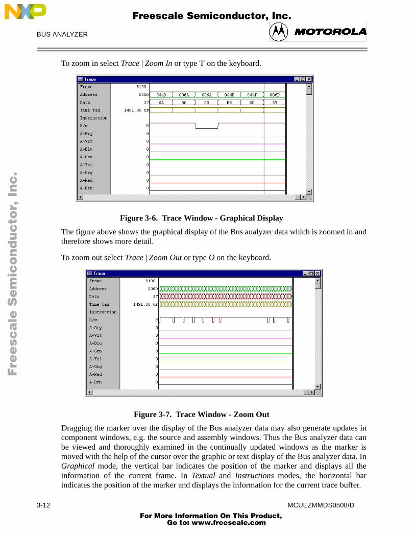
3.4.3 Graphical Display
The figures 3-6 and 3-7 below shows the graphical display of the Bus analyzer datagraphical representation of the Bus analyzer data gives a better overview than the textuSwitching between the different display formats can easily be done at any time by sethe menu entries in the Trace menu. The leftmost sections of the figure display a textdescription of the current frame with information about frame number, events, values odata and address bus, time tag value, etc.
In the graphical display it is possible to 'zoom in' or 'zoom out' either to see more detailget a better general view. Zoom in / Zoom out are available in the Trace popup menu.
MCUEZMMDS0508/D 3-11 For More Information On This Product,
Go to: www.freescale.com
BUS ANALYZER
in and
ates inata canker isata. Inll therffer.
F
ree
sca
le S
em
ico
nd
uc
tor,
I
Freescale Semiconductor, Inc.n
c..
.
To zoom in select Trace | Zoom In or type 'I' on the keyboard.
Figure 3-6. Trace Window - Graphical Display
The figure above shows the graphical display of the Bus analyzer data which is zoomedtherefore shows more detail.
To zoom out select Trace | Zoom Out or type O on the keyboard.
Figure 3-7. Trace Window - Zoom Out
Dragging the marker over the display of the Bus analyzer data may also generate updcomponent windows, e.g. the source and assembly windows. Thus the Bus analyzer dbe viewed and thoroughly examined in the continually updated windows as the marmoved with the help of the cursor over the graphic or text display of the Bus analyzer dGraphical mode, the vertical bar indicates the position of the marker and displays ainformation of the current frame. In Textual and Instructions modes, the horizontal baindicates the position of the marker and displays the information for the current trace bu
3-12 MCUEZMMDS0508/D For More Information On This Product,
Go to: www.freescale.com

BUS ANALYZER
d click
used
ing
nd to them
F
ree
sca
le S
em
ico
nd
uc
tor,
I
Freescale Semiconductor, Inc.n
c..
.
3.4.4 Time Mesasuring
To reference a frame with a tag value of zero, hold the mouse arrow over an entry anthe right mouse button. The Trace menu appears. Select Set Time Base and the time tag valueswill be displayed relative to the bus cycle of the frame.
3.4.5 ShowLocation
To activate the ShowLocation selection for a frame, select the frame, click the right mobutton to activate the Trace menu, and select ShowLocation. The marker can be positionewith a left mouse click. The source and assembly windows are automatically updated.
3.5 ADD / REMOVE ITEMS IN THE TRACE WINDOW
The Trace window can be supplied with new items. In the default configuration, the followitems are displayed in the window: Frame, Events, Address, Data, Time Tag, Instruction andR/W. It is possible to add new items (predefined and given in a list box in this dialog) aremove them. It is possible to permute items in text or graphic mode simply by dragginginto the window.
Figure 3-8. Items Configuration Dialog
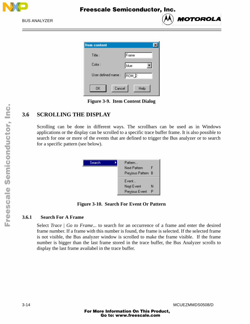
To edit an item, to set its color or to give a specific name, select More.
MCUEZMMDS0508/D 3-13 For More Information On This Product,
Go to: www.freescale.com
BUS ANALYZER
dowsible to
search
sired framerameolls to
F
ree
sca
le S
em
ico
nd
uc
tor,
I
Freescale Semiconductor, Inc.n
c..
.
Figure 3-9. Item Content Dialog3.6 SCROLLING THE DISPLAY
Scrolling can be done in different ways. The scrollbars can be used as in Winapplications or the display can be scrolled to a specific trace buffer frame. It is also posssearch for one or more of the events that are defined to trigger the Bus analyzer or tofor a specific pattern (see below).
Figure 3-10. Search For Event Or Pattern
3.6.1 Search For A Frame
Select Trace | Go to Frame... to search for an occurrence of a frame and enter the deframe number. If a frame with this number is found, the frame is selected. If the selectedis not visible, the Bus analyzer window is scrolled to make the frame visible. If the fnumber is bigger than the last frame stored in the trace buffer, the Bus Analyzer scrdisplay the last frame availabel in the trace buffer.
3-14 MCUEZMMDS0508/D For More Information On This Product,
Go to: www.freescale.com

BUS ANALYZER
ialog
ted
tches
findlso be
e isund,
F
ree
sca
le S
em
ico
nd
uc
tor,
I
Freescale Semiconductor, Inc.n
c..
.
Figure 3-11. Search Frame Dialog
3.6.2 Search For Events
To search for an occurrence of an event select one or more events in the Search EventSpecification box.
Figure 3-12. Search Event Specification Dialog
OK Button If you press the OK button, the selected event(s) is(are) stored and the dbox closes.
Forward To search forward select Forward and the search event is set to the selecevent and a search is done to find the next frame which matches the specified event.
Backward To search backward select Backward and the search event is set to the selected event and a search is done to find the previous frame which mathe specified event.
3.6.3 Next Event
To search for the next occurrence of the selected events, open the Trace pup-up menu andselect Search | Next Event. This command searches forward from the selected frame to the next frame which matches the specified event. The Next Event command can aactivated without opening the Trace menu by pressing the key N on the keyboard, withoutactivating the Trace menu. If a frame is found, this frame is selected. If the selected framnot visible, the Bus analyzer window scrolls to make the frame visible. If no frame is foan error message appears in an error dialog box.
MCUEZMMDS0508/D 3-15 For More Information On This Product,
Go to: www.freescale.com

BUS ANALYZER
o find aalso be
dow isn in an
ed buslips and
defined
hows
F
ree
sca
le S
em
ico
nd
uc
tor,
I
Freescale Semiconductor, Inc.n
c..
.
3.6.4 Previous Event
Open the Trace pop-up menu and select Search | Previous Event to search for the previousoccurrence of the event. This command searches backwards from the selected frame tprevious frame which matches the specified event. The Previous Event command can activated by pressing the key P on the keyboard, without activating the Trace menu. If a frameis found, this frame is selected. If the selected frame is not visible, the Bus analyzer winscrolled to make the frame visible. If no frame can be found, an error message is showerror dialog box.
3.6.5 Search For A Pattern
To search for a frame with a specific pattern, define the search pattern, to find all storcycles that match the pattern. The pattern consists of an address, a data word, logic cfour miscellaneous signals. Select Trace | Search|Pattern...
Figure 3-13. Search For Pattern
Within the above dialog box, the search pattern can be defined in the same way as it is in the Trigger Specification Dialog Box.
The Bus analyzer will look at specific collected cycles, match the specific frame that sthe pattern and display this area in the window of the Debugger.
Address Specify the Address that should be matched.
Data Specify the Data value that should be matched.
3-16 MCUEZMMDS0508/D For More Information On This Product,
Go to: www.freescale.com

BUS ANALYZER
er the statesttern to
t
wn
e an
F
ree
sca
le S
em
ico
nd
uc
tor,
I
Freescale Semiconductor, Inc.n
c..
.
Strobes Specify the state of R/W and LIR-X that should be matched.
Group A Clips Toggle to specify each logic clip as High, Low or Don’t Care.
The clips buttons show the Group A and B logic clips with their respective colors.
Logic clips are used to trace the signals in your target system; the way they run undcontrol of the software. When a trigger occurs, a breakpoint is provided that shows theof significant logic signals before, at, and after the breakpoint. That can be used as a pamatch.
Invert To match any frame without the defined pattern select Invert.
OK Button To store the specified values, select OK then close the box.
Cancel Button To remove the dialog box without any parameter being changed, selecCancel.
Next Pattern To search for the next occurrence of the pattern select the entry Trace |Search | Next Pattern. If the pattern is not found, an error message is shoin an error dialog box.
Previous PatternSelect Trace |Search | Previous Pattern to search for the previous occurrencof the pattern. If the pattern is not found, an error message is shown inerror dialog box.
MCUEZMMDS0508/D 3-17 For More Information On This Product,
Go to: www.freescale.com

BUS ANALYZER
le
nd
the
any
F
ree
sca
le S
em
ico
nd
uc
tor,
I
Freescale Semiconductor, Inc.n
c..
.
3.7 DUMPING THE BUS ANALYZER DATA TO A FILE
To dump the Bus analyzer data to a file, open the Trace pop-up menu and select Dump...
Figure 3-14. Dump Bus Analyzer Frames Dialog
Dump File The group box Dump File contains an edit field where the name of the fito which the data is to be written, can be entered.
Select When the button Select is pressed, a standard file select box is opened athe selected file is displayed in the edit field.
Frames to DumpThe elements in the group box Frames to Dump allow you to select the frames that will be dumped to the file.
Just the frames within the range defined by the two edit fields From: and To: are dumped to the file.
All To dump all the frames within the selected range to the file, select All.
Instructions To dump just the frames where an instruction starts (and instruction is inselected range), select Instructions.
OK Button When the OK button is pressed, the dialog box is removed and the Busanalyzer data is dumped to the file.
Cancel Button When the Cancel button is pressed, the dialog box is removed withoutdata being dumped to a file.
3-18 MCUEZMMDS0508/D For More Information On This Product,
Go to: www.freescale.com

MMDS COMMANDS
ed in
er andthe host0.
Rates not rate.”is
with
F
ree
sca
le S
em
ico
nd
uc
tor,
I
Freescale Semiconductor, Inc.n
c..
.
CHAPTER 4
MMDS COMMANDS
4.1 INTRODUCTION
This section describes MMDS-specific commands. MMDS-specific commands are typthe Command Line component or inserted into a command file.
For further details about commands, refer to the MCUez Debugger User’s Manual.
4.2 BAUD RATE COMMAND
Description:
The BAUD command sets the baud rate for communication between the system controllthe host computer. For maximum performance, the baud rate should be set as high as computer can accommodate. The maximum rate is 115200; the default baud rate is 960
If no baud rate is entered, the command displays the Communications BaudSpecification dialog window for interactive selection of the baud rate. If the system doesupport a baud rate, a red error message, “Error: <baud rate> is not a supported bauddisplayed in the Command Line window.
Example:
BAUD 57600
Changes the communication baud rate to 57600.
BAUDDescription: baud rate.
Syntax: BAUD [rate]
rate : Specifies the new baud rate, and must be an integer constant one of the following specific values (decimal):1200, 2400, 4800, 9600, 19200, 28800, 38400, 57600, 115200.
MCUEZMMDS0508/D 4-1 For More Information On This Product,
Go to: www.freescale.com

MMDS COMMANDS
and/orthe Set areble
ared at
F
ree
sca
le S
em
ico
nd
uc
tor,
I
Freescale Semiconductor, Inc.n
c..
.
4.3 TRIGGER COMMANDS
Description:
The CT command clears the values of specified bus analyzer triggers (events), A, B, C D. The command also disables the cleared triggers. The trigger values are set by Trigger (ST) command, and the bus analyzer configuration dialog windows. Triggersenabled by the Trigger Enable (TE) command; Triggers are disabled by the Trigger Disa(TD) command.
Examples:
CT A B
Clears triggers A and B.
CT *
Clears all triggers.
When clearing a trigger which is part of a range, the second trigger in the range is clethe same time.
Example:
If a range is defined between triggers C and D, CT C clears both trigger C and D.
CTDescription: clear trigger.
Syntax: CT < list> | *
list : A list of trigger identifiers.* : All triggers (A, B, C and D).
4-2 MCUEZMMDS0508/D For More Information On This Product,
Go to: www.freescale.com

MMDS COMMANDS
t, or ifcation
er the
also at
ss
ask are
can dress
) in theadded to address.
r clips
F
ree
sca
le S
em
ico
nd
uc
tor,
I
Freescale Semiconductor, Inc.n
c..
.
Description:The ST command sets the value of one of the four bus analyzer triggers. If value is seonly the triggered id is entered, the command interpreter displays the Trigger Specifidialog window, with which the user sets a trigger value interactively.
id Specifies the trigger id of the analyzer trigger, A, B, C, or D.
! The inversion operator, which applies to the entire trigger, as defined. When! is specified, and an address, data value, and clip value are specified, the triggoccurs when the address is not the specified value, or the data value is not specified value, or the clip value is not the specified value. When ! is specified and a range is specified, the trigger occurs at values outside the range and the lowest value in the range.
address An address to which a trigger is set. The address is specified with an addreconstant, as follows:
<address>[:<mask>]
When a mask is entered, only the bits of the address that correspond to ones in the mused in the comparison.
address range A range of addresses within which a trigger is set. The address rangebe specified with a start and end address constant, or with a starting adand a length value, as follows:
<start-address> [:<mask>][..<end-address >]
or
<start-address> [:<mask>][:: length ]
When a mask is entered, only the bits of the address that correspond to one bits (1smask are used in the comparison. When a length and mask are entered, the length is the start address and the mask is applied to the start address and sum to obtain the end
, The comma indicates that the address, address range, data, data range, clips, orange has been omitted. The omitted item is ignored in the trigger.
STDescription: set trigger.
Syntax: ST[<id> [[!] [(<address> |<address range> | ,) [(<data> | <data range> | ,)[(<clips> | ,)[ LIR= ( X | H | L )]]]] [; R | ; W| ; RW] [; D] ]]
MCUEZMMDS0508/D 4-3 For More Information On This Product,
Go to: www.freescale.com

MMDS COMMANDS
re used
nd a
e masked to thehe end
the
re used
F
ree
sca
le S
em
ico
nd
uc
tor,
I
Freescale Semiconductor, Inc.n
c..
.
data A data value that defines the trigger. The value is specified as follows:
<value>[:<mask>]
When a mask is entered, only the bits of the value that correspond to ones in the mask ain the comparison.
data-range A range of data values that defines the trigger. The data range can bespecified with a start value and an end value, or with a starting value alength, as follows:
<start-value> [:<mask>][..<end-value> ]
or
<start-value> [:<mask>][::< length> ]
When a mask is entered, only the bits of the value that correspond to one bits (1s) in thare used in the comparison. When a length and a mask are entered, the length is addstart value; the mask is applied to the start value and to “start-value + length” to obtain taddress.
clips A15-bit value that defines logic clip signals on the MMDS0508 analyzer for trigger. The value is specified as follows:
<clips>[:<mask>]
When a mask is entered, only the bits of the value that correspond to ones in the mask ain the comparison. For example, the code 0x1F:0x1F , sets all clips of Term A to H. If amask is not specified, the value 0x1F will be assigned by default.
Each trigger clip line has three options:
• H - High• L - Low• X - Don’t Care
The bits of the clips and mask words are as follows:
Bit: Signal:0 Group A- BRN1 RED2 ORG3 YEL4 GRN6 LIR (active low)
;R Trigger on a read bus cycle only.;W Trigger on a write bus cycle only.;RW Trigger on a read or write bus cycle.;D Disable trigger; i.e., set trigger value and disable trigger.LIR Trigger on a specific value for LIR signal.
4-4 MCUEZMMDS0508/D For More Information On This Product,
Go to: www.freescale.com

MMDS COMMANDS
so seen
clipses not
ss 8.
to 10.
F
ree
sca
le S
em
ico
nd
uc
tor,
I
Freescale Semiconductor, Inc.n
c..
.
LIR=H triggers when LIR is high. LIR=L triggers when LIR is low. ; LIR=X triggers when LIR is high or low.
When you specify a range for one of the address or data options, the other option is alas a range. For example, the command STC 8 20..40 is interpreted as STC 8.. 820..40 , and the command STC 8..9 20 is interpreted as STC 8..9 20..20 .
If neither R nor W is specified, the trigger defaults to a read/write bus cycle.
You can set the LIR signal with the clips (bit 6) or the LIR option.
The address, data, or clips will be ignored if the matching mask is specified as zero.
If a bit is set in both the clips and masks, the trigger is set to high (-H). If a bit is not set inand is set in masks, the trigger is set to low (-L). If a bit is not set in mask, the trigger dodepend on the state of the clip.
Examples:
STA 0x1000
Sets analyzer trigger A to match accesses at address $1000.
STB , 4
Sets analyzer triggers B to match accesses with a value of 4, at any address.
STC 8 20..40
Sets analyzer triggers C and D to match accesses using a value from 20 to 40 at addre
STC 8..10 20
Sets analyzer triggers C and D to match accesses using value 20 at an address from 8
NOTE
Bits set to 0 are “Don’t Care” bits. Bits set to 1 are bits that expect the value forAddress, Data, or Clip. Bits set to 0 are in a position that accepts 0 or 1. Bits setto 1 are in a position that only accepts values from the address fields. For thecode: Address 0xC000 Mask 0xFFFC , the trigger is detected for 0xC000and 0xC001 , 0xC002 , or 0xC003 is loaded in the address bus. For the code:Address 0x00B0 Mask 0x00F0 , the trigger is detected when an address inthe range [0xB0 ..0xBF] is loaded.
MCUEZMMDS0508/D 4-5 For More Information On This Product,
Go to: www.freescale.com

MMDS COMMANDS
(d,
(d,
F
ree
sca
le S
em
ico
nd
uc
tor,
I
Freescale Semiconductor, Inc.n
c..
.
Description:
The TD command disables specified triggers. Triggers are set by the Set TriggerST)command, and are enabled by the Trigger Enable (TE) command. Another related commanthe Trigger Clear (CT) command, clears all triggers.
Examples:
TD A,B
Disables triggers A and B.
TD *
Disables all triggers.
Description:
The TE command enables specified triggers. Triggers are set by the Set TriggerST)command, and are disabled by the Trigger Disable (TD) command. Another related commanthe Trigger Clear (CT) command, clears all triggers.
Examples:
TE A B
Enables triggers A and B.
TE *
Enables all triggers.
TDDescription: trigger disable.
Syntax: TD < list> | *
list : A list of triggers to disable; each trigger is either A, B, C or D, separated from following triggers by a comma or space character.* : All triggers (A, B, C and D).
TEDescription: trigger enable.
Syntax: TE < list> | *
list : A list of triggers to enable; each trigger is either A, B, C or D, separated from following triggers by a comma or a space character.* : All triggers (A, B, C and D).
4-6 MCUEZMMDS0508/D For More Information On This Product,
Go to: www.freescale.com

MMDS COMMANDS
s when of the
cles. If
e that begins
framean not
d
r
F
ree
sca
le S
em
ico
nd
uc
tor,
I
Freescale Semiconductor, Inc.n
c..
.
4.4 BUS ANALYZER COMMANDS
Description:
The ARM command arms the bus analyzer. When armed, the analyzer records bus cyclethe emulator is executing user code. Arming the analyzer clears the current contentstrace buffer. Use the disarm analyzer (DARM) command to disarm the analyzer.
Description:
DARM disarms the bus analyzer. When disarmed, the analyzer does not record bus cythe bus analyzer is disarmed, this command does nothing. ARM arms the analyzer.
Description:
The GE command searches forward or backward in the analyzer trace buffer for a frammatches the search event defined with this command. For a forward search, the searchat the frame immediately following the current frame; a backward search begins at theimmediately preceding the current frame.This is a specific bus analyzer command and cbe used if the bus analyzer is not opened.
Example:
GE A B
Moves the cursor to the next frame which contains the event A and/or B.
ARMDescription: arm bus analyzer.
Syntax: ARM
DARMDescription: disarm bus analyzer.
Syntax: DARM
GEDescription: go to event.
Syntax: GE <list> | * [;B]
;B : Specifies backward search. When this option is omitted, a forwarsearch is performed.list: A list of events (A, B, C and D) separated by a space character oa comma.
MCUEZMMDS0508/D 4-7 For More Information On This Product,
Go to: www.freescale.com

MMDS COMMANDS
cified moveshe bus
es theing. Whene cursor is notearchesecific
is ult
rd
F
ree
sca
le S
em
ico
nd
uc
tor,
I
Freescale Semiconductor, Inc.n
c..
.
Description:
GF moves the cursor to a specified trace buffer frame. When the number of the speframe is greater than the number of frames currently stored in the buffer, the commandto the last frame.This is a specific bus analyzer command and can not be used if tanalyzer is not opened.
Examples:
GF 4096Moves the cursor to frame 4096.
GF 32768Moves the cursor to the last frame in the buffer.
Description:
GP searches forward or backward in the analyzer trace buffer for a frame that matchsearch pattern defined with the SP command. A forward search, begins at the frame followthe current frame. A backward search begins at the frame preceding the current framethe search finds a frame that matches the search pattern, the command positions the linon the matching frame in the center of the screen, vertically. When a matching framefound, the line cursor is not moved. When no search pattern is defined, the command sfor any pattern, i.e. the line cursor moves to the next line (or preceding line).This is a spbus analyzer command and can not be used if the bus analyzer is not opened.
Examples:
GP
Searches forward for the next frame that matches the search pattern.
GP ;B
Searches backward for the previous frame that matches the search pattern.
GFDescription: go to frame.
Syntax: GF <frame>
frame : Specifies a frame number in the range of 1..8191. The framealways specified as a decimal number, regardless of the current defanumber base.
GPDescription: Go to Analyzer Search Pattern.
Syntax: GP [;B]
;B : Specifies a backward search. When this option is omitted, a forwasearch is performed.
4-8 MCUEZMMDS0508/D For More Information On This Product,
Go to: www.freescale.com

MMDS COMMANDS
tracee lyzer is
all nge
F
ree
sca
le S
em
ico
nd
uc
tor,
I
Freescale Semiconductor, Inc.n
c..
.
Description:
The LT command copies the content of the bus analyzer trace buffer to the log file. Thebuffer is logged in the current view format. An LF command to initiate logging must bexecuted before entering an LT command. The target must be stopped to execute anLTcommand. This is a specific bus analyzer command and can not be used if the bus ananot opened.
Examples:
LF logfile
Open the logging file.
LT
Copy all the trace buffer to the logging file.
NOLF
Close the logging file.
LTDescription: log trace.
Syntax: LT [<range>]
range : Specifies a range of frames to be copied. If range is omitted,frames in the trace buffer are copied. The default number base for rais decimal.
MCUEZMMDS0508/D 4-9 For More Information On This Product,
Go to: www.freescale.com
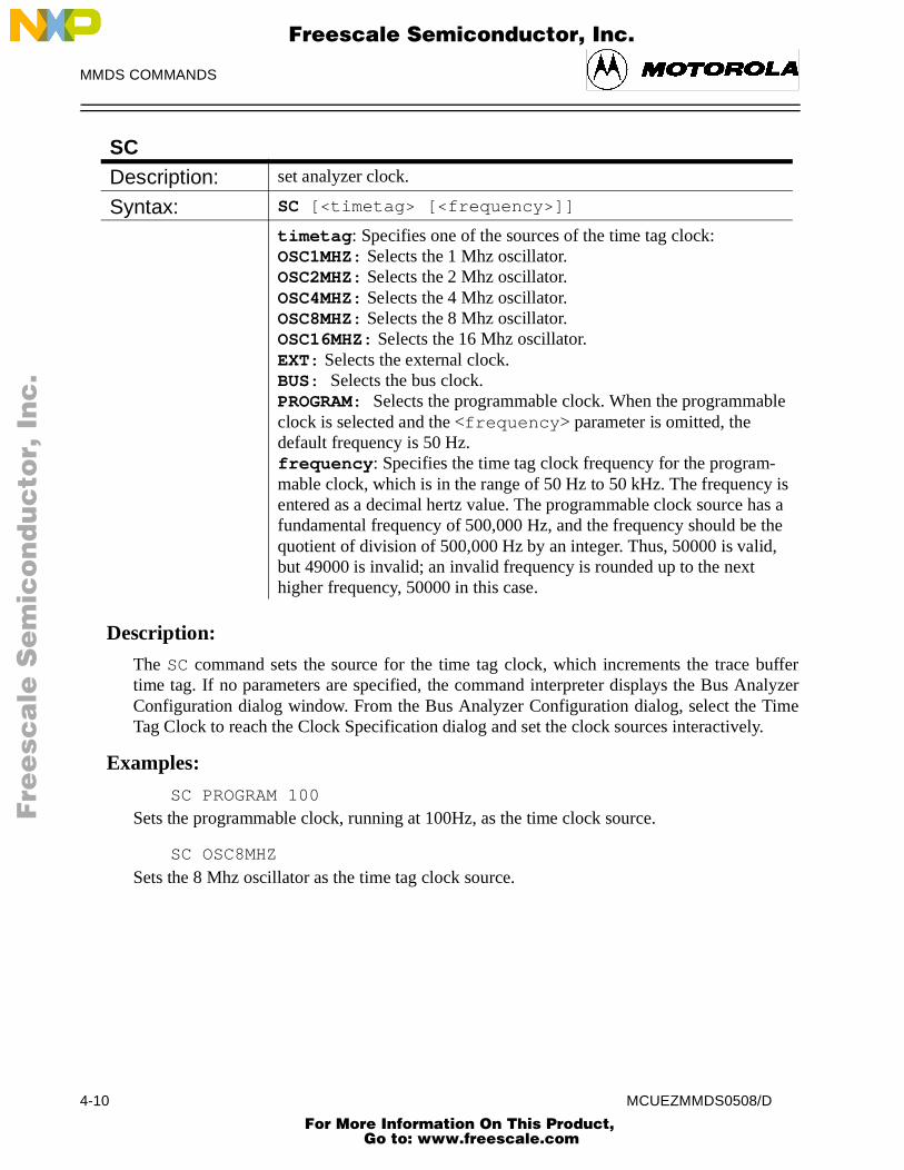
MMDS COMMANDS
bufferalyzerime.
le
is as a he ,
F
ree
sca
le S
em
ico
nd
uc
tor,
I
Freescale Semiconductor, Inc.n
c..
.
Description:
The SC command sets the source for the time tag clock, which increments the trace time tag. If no parameters are specified, the command interpreter displays the Bus AnConfiguration dialog window. From the Bus Analyzer Configuration dialog, select the TTag Clock to reach the Clock Specification dialog and set the clock sources interactively
Examples:
SC PROGRAM 100
Sets the programmable clock, running at 100Hz, as the time clock source.
SC OSC8MHZ
Sets the 8 Mhz oscillator as the time tag clock source.
SCDescription: set analyzer clock.
Syntax: SC [<timetag> [<frequency>]]
timetag : Specifies one of the sources of the time tag clock:OSC1MHZ: Selects the 1 Mhz oscillator.OSC2MHZ: Selects the 2 Mhz oscillator.OSC4MHZ: Selects the 4 Mhz oscillator.OSC8MHZ: Selects the 8 Mhz oscillator.OSC16MHZ: Selects the 16 Mhz oscillator.EXT: Selects the external clock.BUS: Selects the bus clock.PROGRAM: Selects the programmable clock. When the programmabclock is selected and the <frequency > parameter is omitted, the default frequency is 50 Hz.frequency : Specifies the time tag clock frequency for the program-mable clock, which is in the range of 50 Hz to 50 kHz. The frequencyentered as a decimal hertz value. The programmable clock source hfundamental frequency of 500,000 Hz, and the frequency should be tquotient of division of 500,000 Hz by an integer. Thus, 50000 is validbut 49000 is invalid; an invalid frequency is rounded up to the next higher frequency, 50000 in this case.
4-10 MCUEZMMDS0508/D For More Information On This Product,
Go to: www.freescale.com

MMDS COMMANDS
go toecentattern
alue. values
nt:
ffective
. The
ffective
ffective
F
ree
sca
le S
em
ico
nd
uc
tor,
I
Freescale Semiconductor, Inc.n
c..
.
Description:
The SP command defines a pattern for searching the bus analyzer trace buffer. Thesearch pattern (GP) command performs the search for the pattern defined by the most rSP command. If no parameter is specified for the command, the Bus Analyzer Search PSpecification dialog window is displayed for defining the pattern interactively.
! The inversion operator, which applies to a specified single address or data vWhen ! is specified, the command sets a pattern on addresses and/or data other than the specified address or data value.
address An address to which a pattern is set. The address is specified with a consta
address [: mask]
When a mask is entered, only the bits corresponding to one bits (1s) in the mask are ein the pattern.
, The comma indicates that the address, data, or clips byte has been omittedomitted item matches any value of the omitted type (don’t care).
data Data value that defines the trigger. The value is specified as follows:
value [: mask]
When a mask is entered, only the bits corresponding to one bits (1s) in the mask are ein the pattern.
clips 16-bit value that defines logic clip signals on the for the trigger. The value isspecified as follows:
clips [: mask]
When a mask is entered, only the bits corresponding to one bits (1s) in the mask are ein the pattern.
SPDescription: set analyzer search pattern.
Syntax: SP [!] [(<address> | ,) [(<data> | ,) [(<clips> | ,)[ LIR = (X | L | H) ]]]][ ;R | ;W| ;RW]
MCUEZMMDS0508/D 4-11 For More Information On This Product,
Go to: www.freescale.com

MMDS COMMANDS
). If aa bit
ess.
F
ree
sca
le S
em
ico
nd
uc
tor,
I
Freescale Semiconductor, Inc.n
c..
.
The bits of the clips and mask words are as follows:
;R Search for a read bus cycle only.;W Search for a write bus cycle only.;RW Trigger on a read or write bus cycle.;D Disable trigger; i.e., set trigger value and disable trigger.LIR Trigger on a specific value for LIR signal. LIR=H triggers when LIR is high. LIR=L triggers when LIR is low. LIR=X triggers when LIR is high or low.
If a bit is set in both “clips” and “masks”, the pattern is detected when the bit is high (-Hbit is set in “masks” but not in “clips”, the pattern is detected when the bit is low (-L). If is not set in “masks”, the pattern does not depend on the state of the clip.
Examples:SP 0x1000
Sets analyzer search pattern to search for accesses at address $1000.
SP , 4
Sets analyzer search pattern to search for accesses with a data value of 4, at any addr
SP 8 20
Sets analyzer search pattern to search for accesses using a value of 20 at address 8.
NOTE
Bits set to 0 are “Don’t Care” bits. Bits set to 1 are bits that expect the value forAddress, Data, or Clip. Bits set to 0 accept 0 or 1. Bits set to 1 only accept valuesfrom address fields. For Address 0xC000 Mask 0xFFFC , the searchpattern is detected for 0xC000 and 0xC001 , 0xC002 , or 0xC003 is loaded inthe address bus. For Address 0x00B0 Mask 0x00F0 , the search pattern isdetected when an address in the range [0x00B0 ..0xFFBF] is loaded.
Bit: Signal: Bit: Signal:0 Group A - BRN 8 Group B - BRN1 RED 9 RED2 ORG 10 ORG3 YEL 11 YEL4 GRN 12 GRN5 BLU 13 BLU6 LIR 14 VLT7 GRY 15 GRY
4-12 MCUEZMMDS0508/D For More Information On This Product,
Go to: www.freescale.com

MMDS COMMANDS
ed, thect theuencer
t is es. nt is
na-
F
ree
sca
le S
em
ico
nd
uc
tor,
I
Freescale Semiconductor, Inc.n
c..
.
Description:
The SQ command sets the analyzer sequencer mode. If no parameters are specificommand interpreter displays the Bus Analyzer Configuration Dialog, so you can seleSequencer Setup dialog window and program the sequencer interactively. The SeqSetup dialog window can also be invoked from the Setup menu.
Examples:
SQ ALL 100
Specifies 100 bus cycles. After 100 cycles, the analyzer disarms and stops recording.
SQ EVENT 10 ;S
Specifies recording 10 event cycles, then stopping the emulator.
SQDescription: set sequencer.
Syntax: SQ [<mode> [<count>] [;S] ]
mode: Selects the sequencer mode, one of the following:ALL Records all bus cycles.EVENT Records events only.SEQ0 Sequential recording mode “A+B+C+D”.SEQ1 Sequential recording mode “A+B->C+D”.SEQ2 Sequential recording mode “A->B->C D<-”.SEQ3 Sequential recording mode “A->B->C ->D”.SEQ4 nth event after “A+B+C+D”.
count : Specifies terminal count for the ALL and EVENT modes as a decimal value. Causes count frames of the appropriate type to be recorded. Then the analyzer stops recording and is disarmed. If counomitted, the analyzer records continuously whenever the emulator isrunning. Specifies post-trigger count (decimal) for the sequential modCauses count bus cycles to be recorded after the trigger point. If couomitted, the default is 1. If <count> is not included after ALL, the frames for all cycles are recorded. If <count> is not included after EVENT, all the events are recorded.;S : Specifies stopping the emulator when recording stops. Thus the alyzer can be used as a sequenced breakpoint machine.
MCUEZMMDS0508/D 4-13 For More Information On This Product,
Go to: www.freescale.com

MMDS COMMANDS
of theference
ic bus
ts
F
ree
sca
le S
em
ico
nd
uc
tor,
I
Freescale Semiconductor, Inc.n
c..
.
Description:
The TT command displays the difference between the time tags in the two trace framesanalyzer display. When frame numbers are not entered, the command displays the difbetween the beginning and ending frames.
Examples:
TT
Displays the difference between the beginning and ending frames in the trace buffer.
TT 80
Displays the difference between frame 80 and the ending frame in the trace buffer.
TT 10 40
Displays the difference between frames 10 and 40 in the trace buffer.
Description:
The VA command selects the display format of the analyzer trace buffer. This is a specifanalyzer command and can not be used if the bus analyzer is not opened.
Example:
VA MODE=MIX
Selects mixed view mode.
TTDescription: display time tag difference.
Syntax: TT [<sframe> [<eframe>]]
sframe : The starting frame number.eframe : The ending frame number. When eframe is omitted, the endframe in the trace buffer is used in calculating the difference.
VADescription: analyzer view.
Syntax: VA [MODE=(MIX | INS | GRAPH)]
MODE=: When followed by one of the three following keywords, selecthe mode of the bus analyzer window display.MIX: Mixed view mode.INS : Instruction view mode.GRAPH: Graphical view mode.
4-14 MCUEZMMDS0508/D For More Information On This Product,
Go to: www.freescale.com

MMDS COMMANDS
ntrols
F
ree
sca
le S
em
ico
nd
uc
tor,
I
Freescale Semiconductor, Inc.n
c..
.
4.5 TARGET SIGNAL EMULATION COMMANDS
Description:
The SIG command enables or disables control signals from the target MCU, and coemulation. If a signal or list of signals is entered with neither ENABLE nor DISABLE, thesignal(s) are enabled.
Example:
SIG ENABLE RESETIN
Enables the ‘reset in’ signal from the target system.
4.6 RESET COMMANDS
Description:
The RESET command resets the target MCU.
Examples:
Reset Go
Resets the MCU and does a GO from Reset.
Reset
Resets the MCU and stops (default setting).
SIGDescription: set emulator signals.
Syntax: SIG [ [ENABLE] <signal> {<signal>}] [ DISABLE <signal> {<signal>}]
signal : The signal to be enabled or disabled. Available signals are RESETIN and RESETOUT.ENABLE: Connect the signal from the target system.DISABLE: Disconnect the signal from the target system.
RESET
Description: reset target MCU.
Syntax: reset [GO | STOP]
GO: Resets the MCU and does a Go from Reset.STOP: Resets the MCU and stops (default).
MCUEZMMDS0508/D 4-15 For More Information On This Product,
Go to: www.freescale.com

MMDS COMMANDS
tocolter is
r in
d
F
ree
sca
le S
em
ico
nd
uc
tor,
I
Freescale Semiconductor, Inc.n
c..
.
4.7 PROTOCOL COMMANDS
Description:
The PROTOCOL command allows user to display or not the communication probetween the debugger and the server in the command line window. If no paramespecified, the default is ON.
PROTOCOL
Description: Display communication protocol between the server and the debuggethe Command Line component Window.
Syntax: PROTOCOL [ON | OFF]
ON: Protocol displayed in the command line window (default value).OFF: Protocol is not displayed in the command line window or loggein the log file.
4-16 MCUEZMMDS0508/D For More Information On This Product,
Go to: www.freescale.com