i:'% · i air or the rapid changes in attitude required in following a noisy steering dot ......
TRANSCRIPT
ONR-70-3, October 1970
Research supported by:
S.:::::::.:......:::::: ~Office of Naval Research~~~~~~~~~~..... ................. .......... . Ofc fNvlRsac
•,.Contract N00014-67-A-0305-0014Work, Unit Number NR 196-092
.wu
. . . . .. .....'.+... .. :.:.:.: . '
Annual Summary ReportTHE FREQUENCY-SEPARATED
DISPLAY PRINCIPLE: PHASE II
I:'% David C. Denney* Steven L. Johnson
Stanley N. Roscoe
S Engineering Psyc:hology ProgramsOffice f Naval Research
University of Illinois
Urbana-Champaign Campus
-vAVIATION RESEARCH LABORATORY
INS)ITUTrE OF AVIATION
University of Illinois-WiIlard Airport
} !OSavoy, Illinois
NATIONAL TECHNICAL This document hos been dzoproved for public releaseINFORMATION SEICE and-salo; its distribution is unlimited.
springliold, Va. 27151
.........
i
Annual Summary Report
THE FREQUENCY-SEPARATED DISPLAY
PRINCIPLE: PHASE II
zPrpared by:
David C. DenneySteven L. Joinson
Approved by:Stanley N. Roscoe
This document has~been approved for pubficrelease and sale; its distribution is unlimlied.
FI
[ INTRODUCTION
i This is an annual report summarizing the work performed on Contracl
N0014-67-A-0305-0014 during the period 1 April 1969 through 31 October 1970.
I, The report includes: 1) a brief review of the frequency-separated display prob-
lem, 2) a summary of the work accomplished during Phase I, 3) work accomplished
JI during Phase II, 4) research plans for Phase III, and 5) personnel involved in the
research. Two Technical Reports have been issued under this contract: ONR-70-
ii 1, June 1970, and ONR-70-2, October 1970.
fTHE DISPLAY MOTION RELATIONSHIP PROBLEM
:The Problem
Over the years the most controversial issue in flight display design has
been the question of what should move, the airplane or the outside world. The
issue manifests itself in many separate issues involving all dimensions of aircraft
control including attitude, altitude, heading, and speed and their derivatives.
The issues are not simple: although the bulk of the experimental evidence favors
having the aircraft move, most modern flight displays have inside-out presentations
with moving scales, moving horizons, and fly-to moving indices.
It must be concluded that the basic moving-horizon type of attitude presen-
tation, for example, is so well established and its interpretation so over-learned
j by pilots that its basic movement relationships will never be changed. Still the
fact that pilots continue to make critica! control reversals using the moving-horizon
Il display cannot be ignored. We must try to find ways of improving the presentation
of attitude information without disrupting pilots' present habit patterns and preferences.
I
I

-2-
I If one looks carefully at the problem of attitude control reversals, it
Ibecomes apparent that the reversal phenomenon is usually associated with a
sudden change in attitude such as a dropped wing caused by a gust of turbulent
I air or the rapid changes in attitude required in following a noisy steering dot
in an air-to-air attack. In slow routine maneuvers pilots have little trouble
I with the moving horizon. The problem seems to be a:ociated almost exclusively
with the high frequency components cf the display indications. In other words,
Iit appears that the critical consideration is that the elements of a dikplay that
respond immediately to the pilot's control inputs move in the expected direction.
It appears that the direction of movement of the more slowly responding display
indications is far-less critical.
I The Principle of Frequency Separation
These observatons lead to the notion of the frequency separation
I princ!pie of display which has been propagated by various people but never
explicitly tested in any formal experimental program. The best known ex-
il ample of tile frequency separation principle is the so-called kinalog display
system proposed by Lawrence Fogel in 1959.
Fogel demonstrated an attitude-director display system in which the
initial response of the attitude presentation was outside-in. For example,
4. if the pilot moved his stick to the right to initiate a right turn, the air-
craft symbol initially rotated clockwise. As the uircraft established its
ii right turn, the horizon line on the display and the aircraft symbol both
gradually rotated counterclockwise so that in a steady-state turn the air-
Icraft's bank angle was indicated by a tilted horizon line. Upon rolling out
of the turn, once again the first indication of the display was the counter-
I clockwise rotation-of the aircraft symbol followed more s!owly by the
clockwise rotation of the horizon line and-aircraft symbol back to level.
I While this display system was never tested experimentally, the :imp.e
laboratory demonstration of its operation was extremely easy to interpret and
s~showed enough promlise tc warrant further investigation.
I
I
I-3-
Institute of Aviation Studies
I In December of 1968 the Institute of Aviation submitted a proposal to
the Office of Naval Research to study these motion relationship problems.
I Upon receipt of a contract in April of 1969, preliminary studies commenced
at the Institute, and a subcontract was let to Hughes Aircraft Company to
j develop a versatile CRT display apparatus which could be used to study various
aspects of the problem. A description of the make-up of this apparatus and
its capabilities is included in the section, "Summary of Phase I."
SUMMARY OF PHASE I PROGRESS
The effective dates under which the first phase of the program wasI, in progress were 1 April 1969 to 31 March 1970. During that period three
major areas of endeavor were undertaken: development of experimentalI, apparatus under a subcontract with Hughes Aircraft C6mpany, installation
ri of equipment in the Beechcraft C-45H flight resr:arch vehicle, and planning
the formal experiments.
Experimental Apparatus
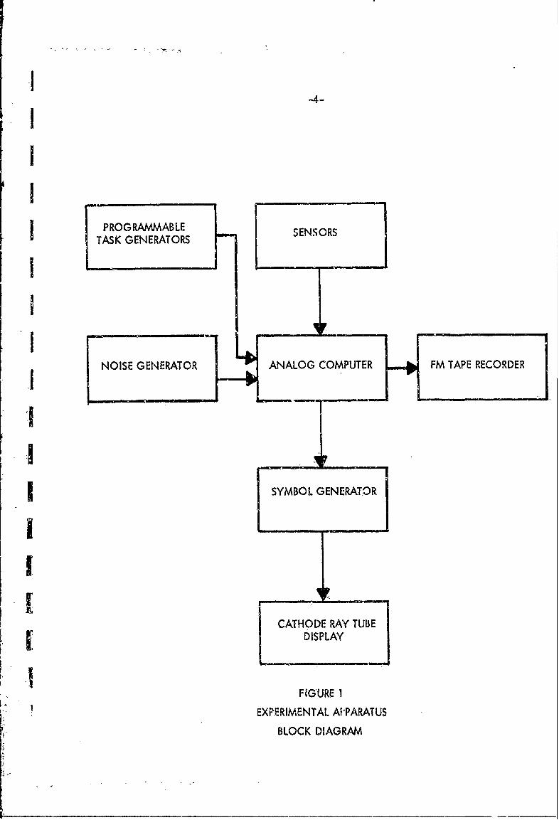
A block diagram of the experimental apparatus-is depicted-in Figure 1.
Flight path commands are generated in two different ways. In one way a
flight-command generator provides digital storage for rapidly replaceable,
programmable vertical and horizontal commands. The two task generators
are rotary stepping switches driven by an electronic timer. The time
increments provided by the timer can be varied to ehange the time between
steps. Movable tabs on the drum of the switch allow various sequences of
horizontal or vertical steering commands to be programmed. The outputs
from the switches go through a digital-to-analog conversion to-provide
J predetermined analog outputs of variable voltage which can be used to drive
the steering command index on the display. A possible range of from 16 positiveI'I
.-4-
I
I I PROGRAMMABLE SENSORS
TAKGENERATORS
NOISE GENERATOR ANALOG COMPUTER FM TAPE RECORDER
2 SYMBOL GENERATORj
CATHODE RAY TUBE
DISPLAY
FIGURE 1
EXPERIMENTAL AI'PARATUS
BLOCK DIAGRAM
".5-I
to 16 negative command values is available at each step in the exercise. There
I are 60 steps which occur at varying intervals averaging five seconds. The out-
put of the digital storage is converted to DC analog voltage steps corresponding
I to commands on the vert::al and horizontal axes. This discrete task provides
for discrimination between displays with respect to reversal errors.'IThe second way in which flight path commands are generated is with
the use of a Gaussian noise generator. This allows the subject to follow
I continuously varying comriands.
Error detection circuitry provides instantaneous values of vertical and
.1| horizontai error to an external recorder which also contains a time reference
channel and a record of flight commands and aircraft responses.
i A symbol generator provides the basic display elements which are
driven from the analog signals for the various modes. While in flight, the
I experimenter can change the mode by simply changing pre-patched panels
on the symbol generator.
The experimental apparatus utilizes an electronically-generated
display approach. This method of display was decided upon because of its
versatility of display format, reliability of operation, similarityto advanced
systems, and mechanical simplicity.
The display is a Tektronix 503 oscilloscope in which the CRT has been
removed and mounted in the instrument panel. The osciiloscope approach was
decided upon because of its availability, performance and rapidity of beam
deflection if needed.
The display is driven by an eight-channel symbol generator mounted
in an, equipment rack which replaces two of the sedis in the cabin of the
aircraft. Line driven outputs are provided to insure good signal propagation
* down the coaxial cables to th, display. The eight channels allow display of
an airplane symbol, a horizon, and a steering dot or circle plus four spare
Kchannels. Two rotation circuits are provided to allow two different sets of
t
i-6-I
symbols to be rotated by independent inputs either in parallel or in series. To
change from a moving-.cirplcne display to a standard display, for example,
requires only that one prepatched board be substituted for another. The symbol
Igenerator also has provision for the insertion of noise into any number of
channels.
I The position and rotation information for the symbol generator comes
from a small Pace TR-20 analog computer. The computer is programmed to
Ido wave shaping and conditioning as well as scaling and summing of the
signals from the sensors and programmable task generators.
I The sensor outputs are-conditioned by appropriate interface circuits to
make them acceptable to the analog computer. The removable patchboard on
Ithe computer allows experimental conditions to be changed in the same manner
as display formats can be changed on the symbol generator, thus allowing
Ifurther versatility.
Error along both the vertical and hor"zontal-axes will be recorded
on an Ampex SP-700 FM magnetic tape recorder. This approach aflows the
data to be analyzed directly from the magnetic tape with the use of a
digital computer.
I Aircraft
The aircraft in this flight research program is a Beechcraft C-45H.
I Rebuilt engines have been installed to maimize the probability of reliable
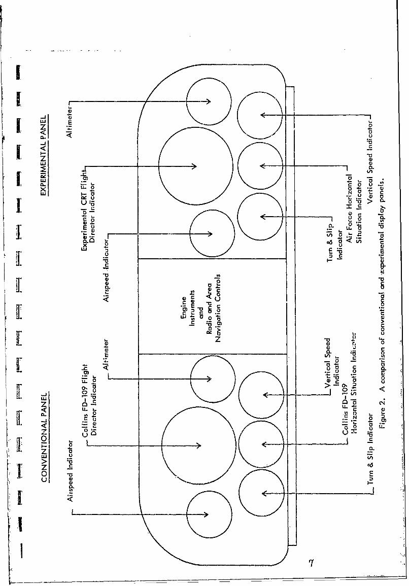
operation. A new flight instrument panel, has been designed, fabricated, and
I installed (Figure 2). This instrument panel includes a Collins FD-109 flight
director system on the left side to 5erve a: a base. n control condi.ti,on against
which any improved display configuration employing the frequency-separation
principle will ultimately be compared.
I Experimental Planning
Preliminary determinations of the experimental variables, flight tasks,
subject sample types and sizes, and performance measures have been made and
I" . . .
r-00
-u o -0
C 0 0 m
-. U a
<- *-
Z 0
'I u
LLO cQC 50 N ct
x0 c
U C 0jV
LU I
z a C4-o
00u 0 - .0141 _ _ _
I-8-
were reviewed on 12 May, 1969, at the University of Iiiinot, Aviation Research
i Laboratory by Dr, Marshall Farr, former project technical monitor from the ONR
Engineering Psychology Branch, and by Dr. Morton Bertin, psychological research
representative from the ONR office in Chi, cgo.
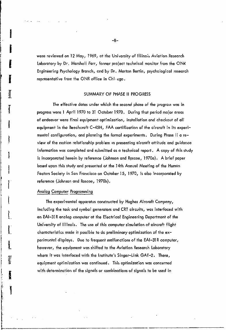
The effective dates under which the second phase of the program was in
progress were 1 April 1970 to 31 October 1970. During that period major areas
of endeavor were final equipment optimization, installation and checkout of all
equipment in the Beechcraft C-45H, FAA certification of the aircraft in its experi-
mental configuration, and planning the formal experiments. During Phase II a re-
view of the motion relationship problem in presenting aircraft attitude and guidance
information was completed and submitted as a technical report. A copy of this study
is incorporated herein by reference (Johnson and Roscoe, 1970a). A brief paper
based upon this study and presented at the 14th Annual Meeting of the Human
Factors Society in San Francisco on October 15, 1970, is also incorporated by
reference (Johnson and Roscoe, 1970b).
Analog Com2 ter Programming
The experimental apparatus constructed by Hughes Aircraft Company,
including the task and symbol generators and CRT circuits, was interfaced with
t_ an EAI-31 R analog computer at the Electrical Engineering Department of the
University of Illinois. The use of this computer simulation of aircraft flight
L_ characteristics made it possible to do preliminary cptimizaticn of the ex-
perimsntal displays. Due to frequent malfunctions of the EAI-31 R computer,
I however, the equipment was shifted to the Aviation Research Laboratory
where it was interfaced with the Institute's Singer-Link GAT-2. There,
I equipment optimization was continued. This optimizatlon was concerned
with determination of the signals or combinations of signa!s to be used in
[1____________ _____________________________________
I -9.-
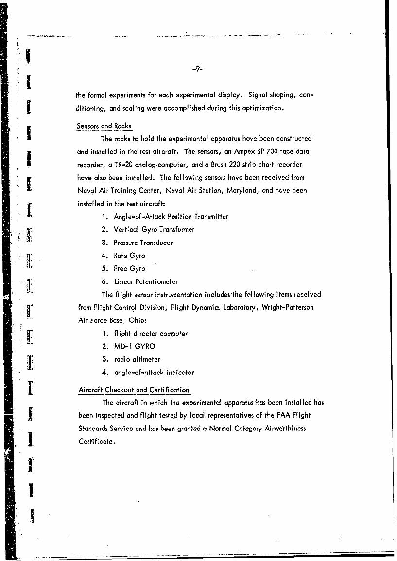
the formal experiments for each experimental displcy. Signal shaping, con-
5! ditioning, and scaling were accomplished during this optimization.
Sensors and Racks
The racks to hold the experimental apparatus have been constructed
and installed in the test aircraft. The .ensors, an Ampex SP 700 tape data
recorder, a TR-20 analogcomputer, and a Brush 220 strip chart recorder
have also been installed. The following sensors have been received from
Naval Air Training Center, Naval Air Station, Maryland, and have been
installed in the test aircraft:
S1. Angle-of-Attack Position Transmitter
2. Vertical Gyro Transformer
3. Pressure Transducer
4. Rate Gyro
5. Free Gyro
6. Linear Potentiometer
The flight sensor instrumentation includes-the following items received
from Flight Control Division, Flight Dynamics Laboratory, Wright-Patterson
Air Force Base, Ohio:
1 . flight director computer
2. MD-i GYRO
3. radio altimeter
4. angle-of-attack indicator
I! Aircraft Checkout and Certification
The aircraft in which the experimental apparatus-has been installed has
been inspected and flight tested by local representatives of the FAA Flight
Standards Seivice ard has been granted a Normal Category Airworthiness
SCertificate.
1110-
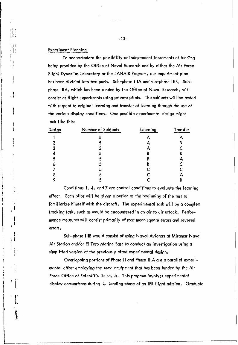
Experiment Planning
To accommodate the possibility-of independent increments of func'ng
being provided by the Off;.'e of Naval Research and by either the Air Force
Flight Dynamics Laboratory or the JANAIR Program, our experiment plan
has been divided into two parts. Sub-phase iliA and sub-phase IIIB. Sub-
phase liA, which has been funded by the Office of Naval Research, will
consist of flight experiments using private pilots. The subjects will be tested
with respect to original learning and transfer of learning through the use of
the various display conditions. One possible experimental design mightlook like this:
Design Number of Subjects Learning Transfer
1 5 A A2 5 A B3 5 A C4 5 B B5 5 B A6 5 B C7 5 C C8 5 C A9 5 C B
Conditions 1, 4, and 7 are control conditions to evaluate the learning
effect. Each pilot will be given a period at the beginning of the test to
familiarize himself with the aircraft. The experimental task will be a complex
tracking task, such as would be encountered in an air to air attack. Perfor-
mance measures will consist primarily of root mean square errors and reversal
errors.
Sub-phase I IIB would consist of using Naval Aviators at Miramar Naval
Air Station and/or El Toro Marine Base to conduct an investigation using a
simplified version of the previously cited experimental design.
Overlapping portions of Phase II and Phase liA are a parallel experi-
mental effort employing the some equipment that has been funded by the Air
Force Office of Scientific, . This program involves experimental
display comparisons during it'. 'anding pha:e of an IFR flight mission. GraduateGrdut
-11-
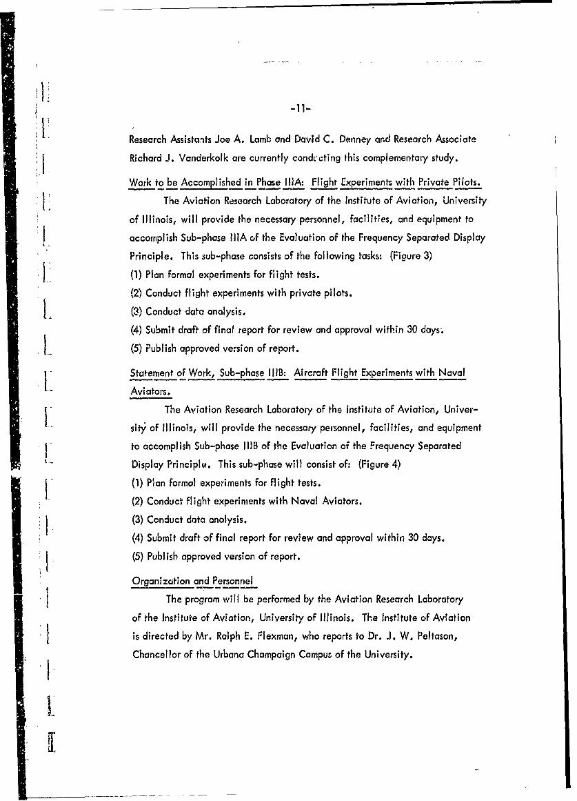
Research Assistants Joe A. Lamb and David C. Denney and Research Associate
Richard J. Vanderkolk are currently condl'cting this complementary study.
Work to be Accomplished in Phase IliA: Flight Experiments with Private Pilots.
The Aviation Research Laboratory of the Institute of Aviation, University
of Illinois, will provide the necessary personnel, facilities, and equipment to
accomplish Sub-phase liA of the Evaluation of the Frequency Separated Display
Principle. This sub-phase consists of the following tasks: (Figure 3)
(1) Plan formal experiments for flight tests.
(2) Conduct flight experiments with private pilots.
L (3) Conduct data analysis.
(4) Submit draft of final report for review and approval within 30 days.
L (5) Publish approved version of report.
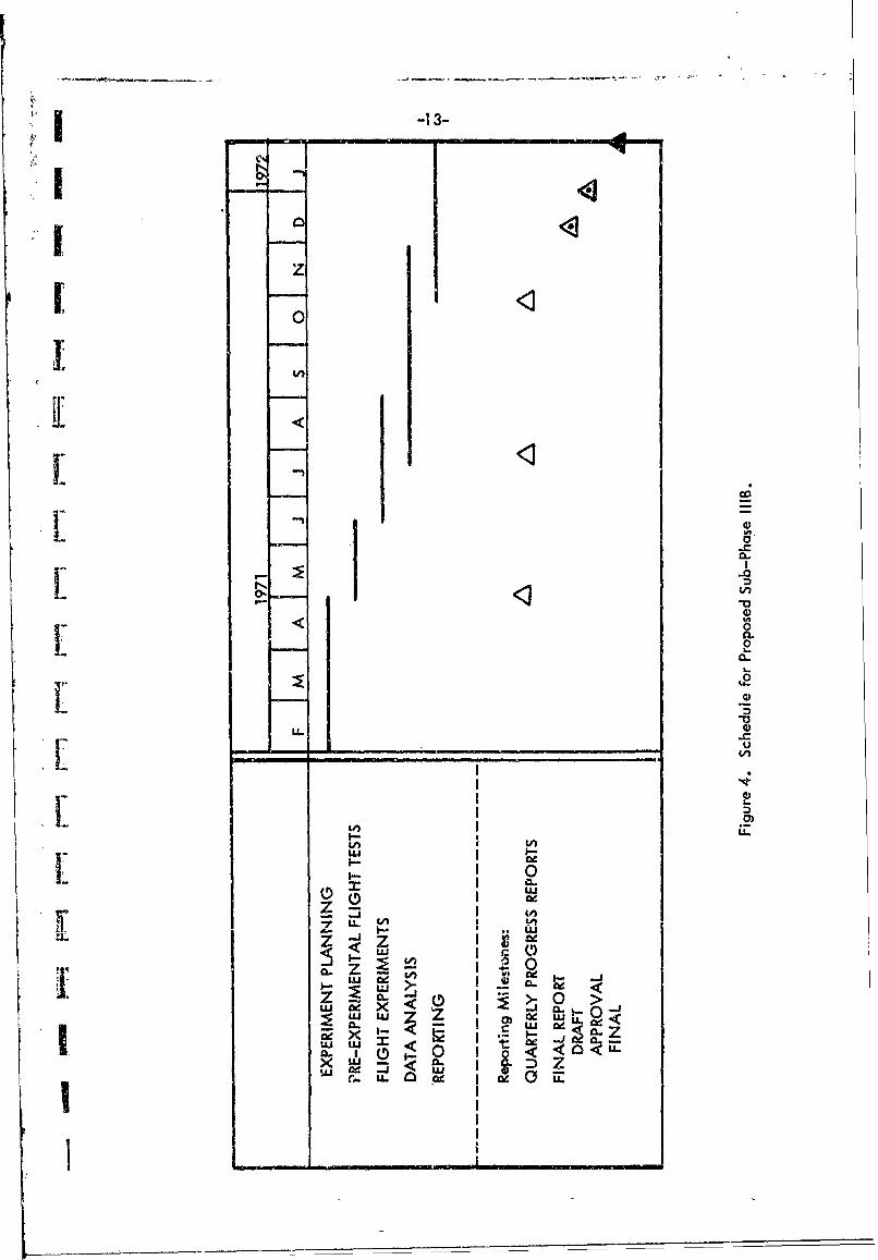
Statement of Work, Sub-phase IIB: Aircraft Flight Experiments with Naval
Aviators.
The Aviation Research Laboratory of the Institute of Aviation, Univer-I-sity of Illinois, will provide the necessary personnel, facilities, and equipment
to accomplish Sub-phase l11B of the Evaluation of the Frequency Separated
Display Principle. This sub-phase will consist of: (Figure 4)
(1) Plan formal experiments for flight tests.
(2) Conduct flight experiments with Naval Aviators.
(3) Conduct data analysis.
(4) Submit draft of final report for review and approval within 30 days.
(5) Publish approved version of report.
Organization and Personnel
The program will be performed by the Aviation Research Laboratory
of the Institute of Aviation, University of Illinois. The Institute of Aviation
is directed by Mr. Ralph E. Flexman, who reports to Dr. J. W. Peltason,
Chancellor of the Urbana Champaign Campus of the University.
I,

-3
fu
0%0
0 z
2 094-
-j -- P- ->
ItCL~ Ij J>-0L
00z Ij c-ou IL l C I
LUL
I o o-<I- Ck D zX
-- -
II00
L CL
z V-
u-uCL. U)-c
-u 0 -1
1~ <)X w . .
a: - I 00
U- W- -J

-14-
The principal investigator will continue to be Dr. Stanley N. Roscoe,
Associate Director for Rerearch of the Institute of Aviation and Head of the
Aviation Research Laboratory. Graduate Research Assistant Steven L. Johnson,
who is currently engaged in research on Phase 11, will continue during Phase Ill.
H. Kingsley Povenmire, who is also currently engaged on Phase II, will continue
to be the project pilot.
With the funding of Sub-phase IIIB, two half-time Graduate ResearchF V Assistants will be hired. One Graduate Research Assistant, Joe Lamb, who
is in aeronautical engineering, will be employed for twelve months, and
one new assistant for three months. In addition, one additional Research
Associate in the field of engineering will be hired.
REFERENCES
a. Johnson, S. L. and Roscoe, S. N. What moves, the airplane or the world?A review of motion relationship problem in presenting aircraft attitude
L and guidance information. Alexandria, Va.: Office of Naval Research,
Contract N 00014-67-A-305-0014, Technical Report ONR-70-1, June
1970. (AD 713179).
b. Johnson, S. L. and Roscoe, S. N. Frequency Separated flight displays. Savoy,
Ill.: University of Illinois, Aviation Research Laboratory, Technical Report
ONR-70-2, October 1970.
I-
I:
' *1 UnclassifiedSecrity, Classification
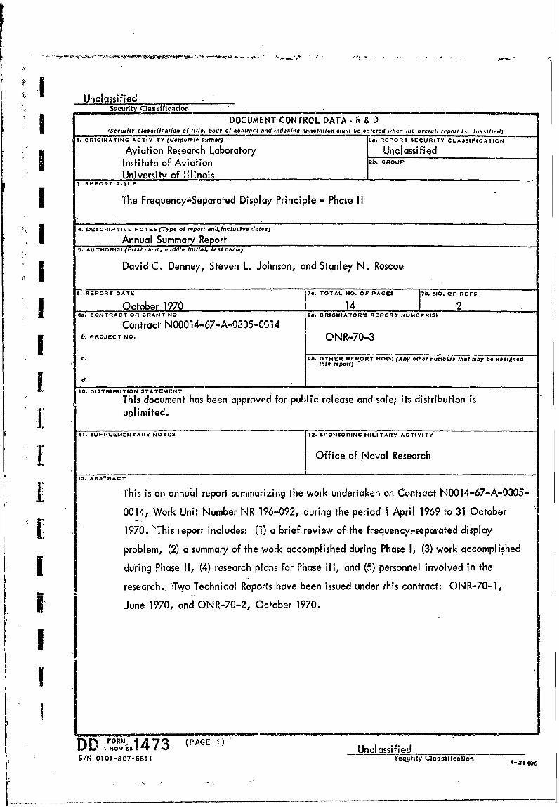
CDOCUMENT CONTROL DATA. R & DfSecurlty classifIcatlon of title, body of abstract and Indexing annotation inu%t be en-ered when Mho overall report i. lIItktrivd)
1. ORIGINATING ACTIVITY (Corporate author) 2a. RCPORT SECURITY CLASSIFICAIlON
Aviation Research Laboratory Unclassified
I Institute of Aviation b. Gnoup
Unjversity of Illinois3. REPORT TITLE
IThe Frequency-Separated Display Principle - Phase I
" -' I4. DZSCRIPTIVC NOTES (7Type of report andl.inclusive dates)
Annual Summary Report5. AUTHORIS (First name, middle Initial, last name)
I David C. Denney, Steven L. Johnson, and Stanley N. Roscoe
0. REPORT OATEr 74. TOTAL NO. OF PAGES jb. CF REFS,
October 1970 14 2On. CONTRACT OR GRANT NO. Oa. ORIGINATOROS RCPORT NUMBERIS)
Contract N00014-67-A-0305-0C14i b. PROJECT NO. ONR-70-3
C. 9b. OTHER REPORT NOIS) (Any other numb6r& that may be aIsignedthis report)
d.
10. DISTRIBUTION STATEMENT
-This document has been approved-for public release and sale; its distribution is- unlimited.
It. SUPPLEMENTARY NOTES 12. SPONSORING MILITARY ACTIVITY
S 3.ASROffice of Naval Research13. ABSTRACT
This is an annual report summarizing the work undertaken on Contract N0014-67-A-0305-
0014, Work Unit Number NR 196-092, during the period I April 1969 to 31 October
1970. "This report includes: (1) a brief review of -the frequency-separated display
problem, (2) a summary of the work accomplished during Phase I, (3) work accomplished
I during Phase II, (4) research plans for Phase III, and (5) personnel involved in the
research., 'Two Technical Reports have been issued under rhis contract: ONR-70-1,
i I June 1970, and ONR-70-2, October 1970.
II
DD Iork 1 51473 (PACE 1) UnclassifiedS/N 0101-807-6811 ccutty Classification
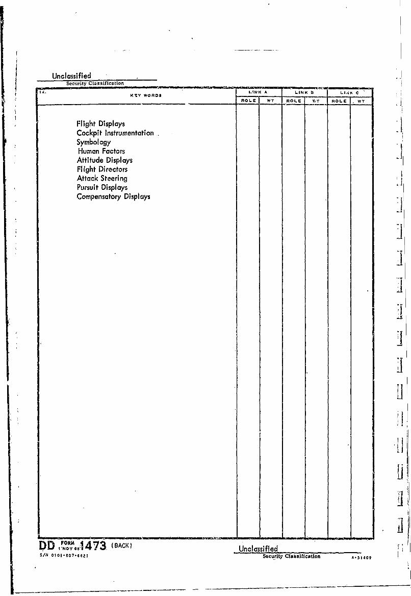
UnclassifiedSecurity Classification
K YWORDS LAINK A LINK 1 LI.AK C
-_ROLE WT ROLE V,T ROLE WT
Flight DisplaysCockpit InstrumentationSymbologyHuman Factors
Attitude DisplaysFlight DirectorsAttack SteeringPursuit DisplaysCompensatory Displays LI
IL
FOR DBACK)D'vNOVa 4 73 Unclassified i
SIN O l-O -e Securty Claaa si cfl ton A-3149