hydrogen production with mixed protonic-electronic ... production with mixed protonic-electronic...
TRANSCRIPT

UF-DOE HiTEC
Hydrogen Production with Mixed Protonic-ElectronicConducting Perovskite Membranes
Eric D. WachsmanUF-DOE High Temperature Electrochemistry Center
Department of Materials Science and EngineeringUniversity of Florida
Gainesville, FL [email protected]
UF-DOE HiTEC
UF-DOE HiTEC
Outline
• Introduction• Fundamentals and Materials Development• Membrane Reactor Fabrication and Results• Recent Membrane Materials Advances• Conclusions

UF-DOE HiTEC
Ni-SrCeO3 porous tubular support•Support for hydrogen membrane•Ni catalyzes endothermic steam reforming orwater gas-shift reaction
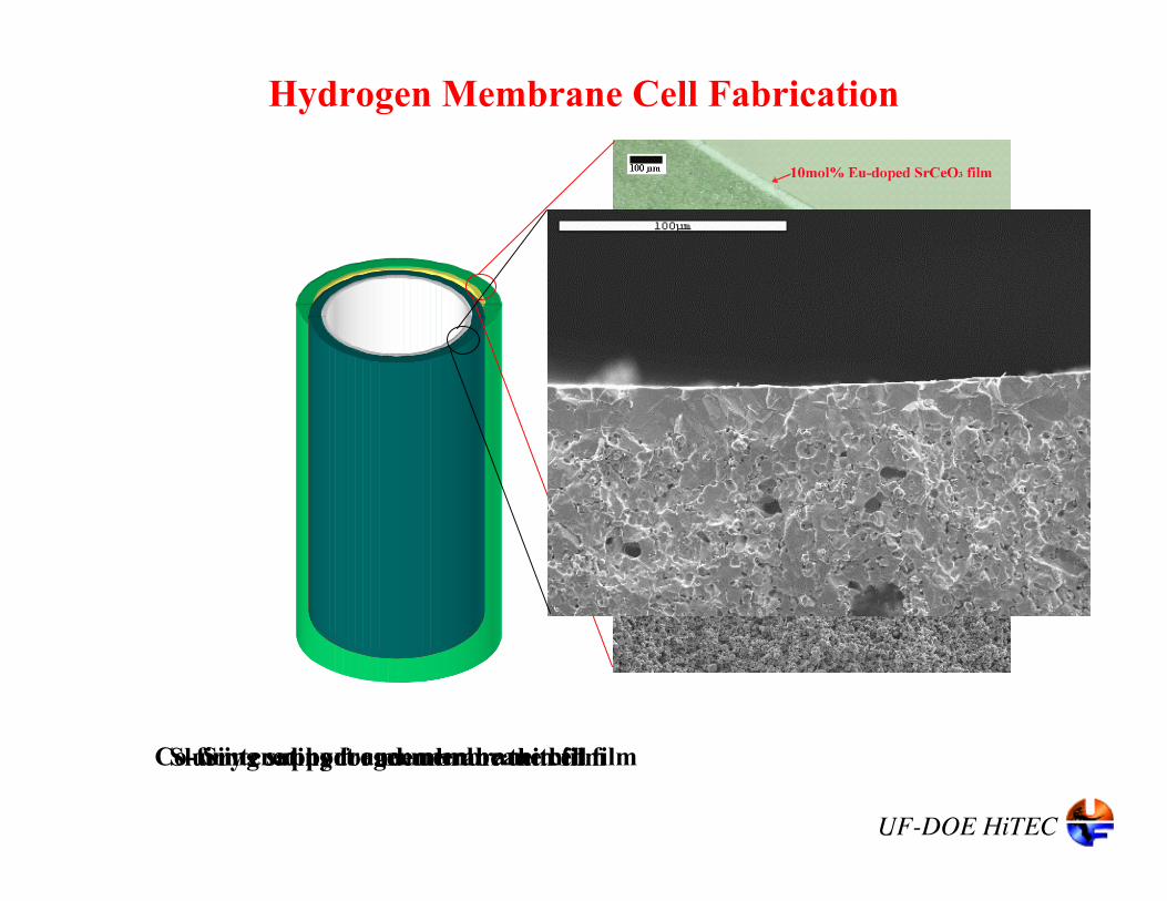
SrCe1-xEuxO3-δ dense hydrogen membrane•Mixed proton-electron conductor•~10 µm dense layer
Oxygen transport membrane•Exothermic oxidation of hydrocarbon feed gas
Concept - Autothermal Catalytic Membrane Reactorfor Production of Pure H2
CO2
Ultimately can produce pure H2 from anyhydrocarbon feed stock:
• Natural gas• Coal based syn gas• Biomass

UF-DOE HiTEC
Cost of Hydrogen Production from Natural Gas*
3.25 H2/CH4
CH4 ~ 0.20C$/m3
~$0.15/m3 H2
~0.015 ¢/liter H2
CH4 + 0.375 O2 + 1.25 H2O = CO2 + 3.25 H2
* Assumes 100% conversion and selectivity,air and water are free, and ignores capital cost

UF-DOE HiTEC
DOE’s Future Gen
• Hydrogen and electricity co-generation from coal• Zero emissions and CO2 capture
“Hydrogen Production from Fossil Fuels with Proton and Oxygen-Ion Transport Membranes,”E. D. Wachsman and M. C. Williams, Interface, Volume 13, No.3, Fall 2004

UF-DOE HiTEC
Outline
• Introduction• Fundamentals and Materials Development• Membrane Reactor Fabrication and Results• Recent Membrane Materials Advances• Conclusions
UF-DOE HiTEC
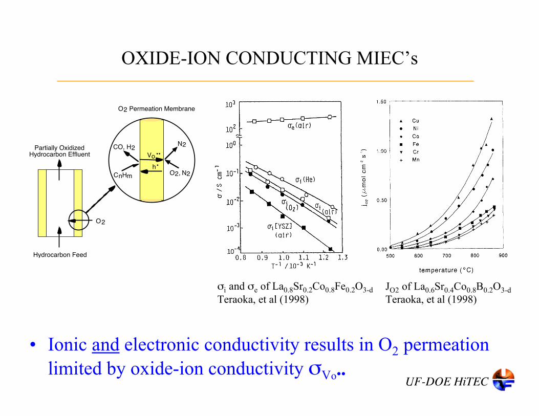
OXIDE-ION CONDUCTING MIEC’s
• Ionic and electronic conductivity results in O2 permeationlimited by oxide-ion conductivity σVo••
σi and σe of La0.8Sr0.2Co0.8Fe0.2O3-dTeraoka, et al (1998)
JO2 of La0.6Sr0.4Co0.8B0.2O3-dTeraoka, et al (1998)
Hydrocarbon Feed
O2 Permeation Membrane
O2, N2h•
Vo••
O2
Partially Oxidized Hydrocarbon Effluent
CnHm
CO, H2N2

UF-DOE HiTEC
OXIDE-ION vs. PROTONIC CONDUCTION
• Oxygen ions jump from a filled (OOx) to a vacant (VO
••) site• H-bonded protons form an OH group (OHO
•)• Protons move around OO
x and jump to neighboring OOx
VO••
OOx
MMx
OHO•

UF-DOE HiTEC
Partially Oxidized Hydrocarbon Feed
H2 Permeation Membrane
H2e’
OHo•
H2
CO, H2, CH4
CO, C2+
Hydrogen Depleted Effluent
SrCeO3-δ layer
Ni-GDC porous support
PROTONIC vs. OXIDE-ION CONDUCTORS
• Protonic conductors have comparable ionic conductivity butnegligible electronic conductivity
• H2 flux limited by electronic conductivity (σe’)
σi and σe of La0.8Sr0.2Co0.8Fe0.2O3-dTeraoka, et al (1998)Iwahara, et al.

UF-DOE HiTEC
• Add electronic conductivity by doping Ce sitewith multivalent cation (M3+/2+) that can bereduced to 2+– MCe” = MCe
’ + e’ (n-type conduction)
• Match ionic radii for– Phase stability– Proton conductivity– > Eu3+/2+
Eu3+
Conductivity of BaCe1-xMxO3-d as a function rM ,Iwahara et al (1993)
Adding Electronic Conductivity to a Proton Conductor
E. D. Wachsman and N. Jiang, October 2, 2001, U.S. Patent No. 6,296,687.

UF-DOE HiTEC
H2 Flux Relationship
Proton flux across calculated using Wagner equation:• Assumes that bulk diffusion is rate limiting step• σt is the total conductivity
– σi = zi q ui [i], (i = OHO•, VO
••, e’)
• Transference number, ti = σi / σt
– High flux requires both high protonic and high electronic conductivity
• F is Faraday’s constant• L is the membrane thickness• Integrate both O2 and H2 potential gradients
!! ++"= •••••••
//
2
/
22
/
//
2
/
22
ln)(2
ln4[1
22
H
HOO
O
OOOO
P
PHeVOHt
P
POVOHtOH
PdtttF
RTPdtt
F
RT
LJ ##
UF-DOE HiTEC
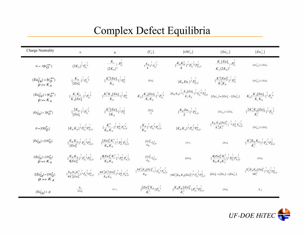
Complex Defect EquilibriaCharge
neutrality n p ][ !!
OV ][ !
OOH ][ /
CeEu ][ //
CeEu
][2!!
= OVn 6
1
3
1
2}2{
"
ORPK
6
1
3
1 2
}2{
O
R
i P
K
K
6
1
3
1
2)
4(
"
OR PK
2
1
12
1
6
13
22}
4{
OHOWR PPKK "
6
1
3
1 2
}2{
][O
RA
ti P
KK
EuK
tCeEuEu ][][ //
=
][][ // !!= OCeVEu
AKp <<
4
1
2
1
2}][
{"
O
t
R PEu
K 4
1
2
12
2}][
{O
R
ti PK
EuK
tEu][
2
1
2
1
2}{
OHtWPEuK
4
1
2
1
2
32
2}][
{O
RA
ti PKK
EuK
tCeEuEu ][][
//=
][][ // !!= OCeVEu
AKp >>
6
1
3
1
2}][
{"
O
tA
Ri PEuK
KK 6
1
3
12
2}][
{O
R
tAi PK
EuKK 6
1
3
2
2}][
{"
O
Ri
tAR
PKK
EuKK
2
1
12
1
3
1
2
1
22}
][{}{
OHO
Ri
tARW PP
KK
EuKKK
"
][][][///CetCe EuEuEu "= 6
1
3
2
2}][
{"
O
Ri
tAR
PKK
EuKK
][2][ / !!= OCeVEu
4
1
2
1
2}][
2{
"
O
t
R PEu
K 4
1
2
12
2}
2
][{
O
R
ti PK
EuK
2
][ tEu 2
1
2
1
2}
2{
OHtW P
EuK
tCeEuEu ][][ /
= 4
1
2
1
2
2
2}][2
{"
O
i
tRA PK
EuKK
][ != OOHn
4
1
8
1
4
1
22}{
OHORWPPKK
"
4
1
8
1
4
14
22}{
"
OHO
RW
i PPKK
K 2
1
4
1
2
1
22}{
""
OHO
W
R PPK
K
4
1
8
1
4
1
22}{
OHORWPPKK
"
4
1
8
1
4
1
44
4
22}
][{
""
OHO
iA
tRWPP
KK
EuKK
tCeEuEu ][][ /
=
][][ / != OCeOHEu
2
1
4
1
2
1
2 22}
][{
OHO
t
RW PPEu
KK " 2
1
4
1
2
122
22}
][{
"
OHO
RW
it PPKK
KEu 1
2
2
][ "OH
W
t PK
Eu
tEu ][
tEu][ 2
1
4
1
2
1
2
2
22}{
OHO
i
RWA PPK
KKK "
][][2 // != OCeOHEu
AKp <<
2
1
4
1
2
1
2 22}][4
{OHO
t
RW PPEu
KK " 2
1
4
1
2
122
22}
][4{
"
OHO
RW
it PPKK
KEu 1
2
2
][ "OH
W
t PK
Eu
tEu][2 2
1
4
1
2
1
2
24
22}
][4{
"
OHO
ARW
it PPKKK
KEu
tEu][
][][2 // != OCeOHEu
AKp >>
4
1
8
1
4
1
22
2
22}
][4{
OHO
tA
iRW PPEuK
KKK " 4
1
8
1
4
1222
22}
][4{
"
OHO
RW
tiA PPKK
EuKK
2
1
4
1
2
122
22}
][4{
""
OHO
W
tRA PPK
EuKK
4
1
8
1
4
1
22
22}][4{
OHOtRWA PPEuKKK"
][][][//Cett EuEuEu "=
4
1
8
1
4
1
2
22
22}
4
][{
OHO
i
tWRA PPK
EuKKK "
pEuCe
=][ /
t
i
Eu
K
][
tEu ][
2
1
2
2
2}
][{
"
O
i
Rt PK
KEu 2
1
4
1
2
2
22}][
{ OHO
i
tWR PPK
EuKK "
tEu][
AK
Charge Neutrality
]2[••
=O
Vn
][]//
[••
=O
VCe
Eu
][OH•
=O
n
]2[]/
[••
=O
VCe
Eu
AKp <<
AKp <<
AKp >>
AKp >>
][]//
[••
=O
VCe
Eu
][OH]/
[•
=OCe
Eu
][OH]//
2[•
=OCe
Eu
][OH]//
2[•
=OCe
Eu
pCeEu =]/
[

UF-DOE HiTEC
Modeling Defect Equilibria and Transport -effect of PH2, PO2, PH2O
S. J. Song, E. D. Wachsman, S. E. Dorris, and U. Balachandran, Solid State Ionics, 149,
1-10 (2002).

UF-DOE HiTEC
Modeling Defect Equilibria and Transport
σi = zi q ui [i]
UF-DOE HiTEC
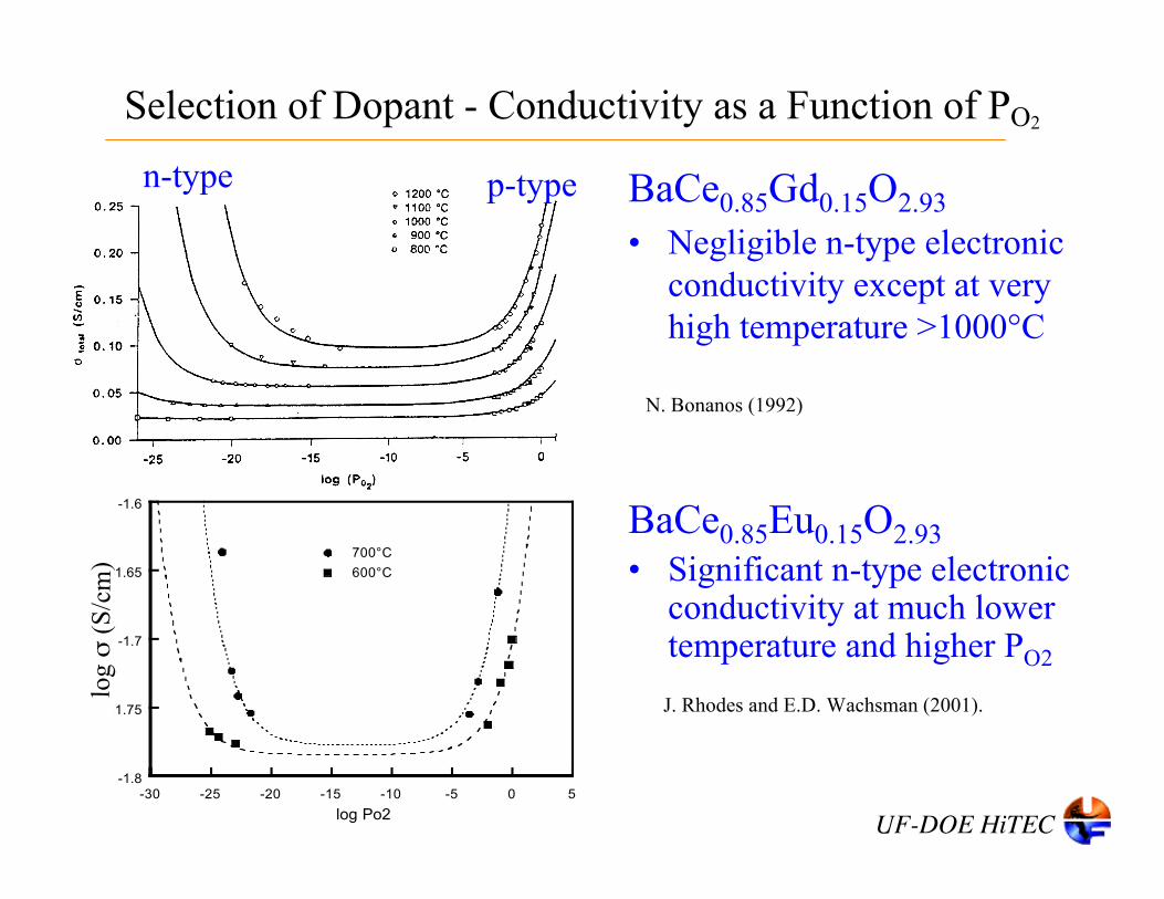
Selection of Dopant - Conductivity as a Function of PO2
BaCe0.85Gd0.15O2.93• Negligible n-type electronic
conductivity except at veryhigh temperature >1000°C
n-type p-type
N. Bonanos (1992)
-1.8
-1.75
-1.7
-1.65
-1.6
-30 -25 -20 -15 -10 -5 0 5
700°C
600°C
log
! (S/cm)
log Po2
log σ
(S/c
m)
BaCe0.85Eu0.15O2.93• Significant n-type electronic
conductivity at much lowertemperature and higher PO2
J. Rhodes and E.D. Wachsman (2001).

UF-DOE HiTEC
• At high temperature (>750°C) permeation is bulk transport controlled– Flux is linear with 1/L
• At lower temperature permeation is surface kinetic controlled
0
0.001
0.002
0.003
0.004
0.005
0.006
600 650 700 750 800 850 900
100% H2 0.75 mm
90% H2 1.00 mm
90% H2 2.00 mm
HY
DR
OG
EN
FL
UX
(cc/c
m 2-m
in)
TEMPERATURE (oC)
0
0.001
0.002
0.003
0.004
0.005
0.006
0.4 0.6 0.8 1 1.2 1.4
HY
DR
OG
EN
FLU
X (
cc/c
m 2
-min
)
1/THICKNESS (mm)
850oC
800oC
750oC
Flux ~ 1/membrane thickness (L)
!! ++"= •••••••
//
2
/
22
/
//
2
/
22
ln)(2
ln4[1
22
H
HOO
O
OOOO
P
PHeVOHt
P
POVOHtOH
PdtttF
RTPdtt
F
RT
LJ ##
H2 Flux Relationship

UF-DOE HiTEC
Outline
• Introduction• Fundamentals and Materials Development• Membrane Reactor Fabrication and Results• Recent Membrane Materials Advances• Conclusions
UF-DOE HiTEC
Slurry coating for membrane thin filmCo-firing support and membrane thin filmSintered hydrogen membrane cell
Hydrogen Membrane Cell Fabrication

UF-DOE HiTEC
Fabrication of Membrane Reactor

UF-DOE HiTEC
Hydrogen Membrane Evaluation
All tubes are continuously leak checked by Ar tracer in feed gas

UF-DOE HiTEC
Hydrogen Permeation and Leak Testing
• Confirms membranes are leak free • Capable of producing 100% purity H2

UF-DOE HiTECHydrogen flux ~ PH2 1/4
Hydrogen Permeation

UF-DOE HiTEC
Activation energy of ~0.9 eV indicates flux limited by σe− σOH• activation energy ~ 0.5 eV
Hydrogen Permeation
0.9240.890.930.960.970.86Activation energy,E (eV)
average value10.600.350.200.075PH2 (atm)

UF-DOE HiTEC
H2 -3% H2O balance Ar / SrCe0.9Eu0.1O3 /He
Hydrogen Permeation
Membrane tubes produce7 cc/min of pure H2

UF-DOE HiTEC
H2 balance He / SrCe0.95Tm0.05O3 / 20% O2 balance He[1] S. Cheng, V. K. Gupta, and J. Y. S. Lin, Solid State Ionics 176 (2005) 2653.
4% H2 -3% H2O balance He / Ni-BaCe0.8Y0.2O3 / N2 with 100ppm H2[2] C. Zuo, T. H. Lee, S.-J. Song, L. Chen, S. E. Dorris, U. Balachandran, and M. Liu, Electrochem. Solid-State Lett., 8 (2005) J35
H2 -3% H2O balance Ar / SrCe0.9Eu0.1O3 /He
Hydrogen Permeation
Area normalized membraneflux comparable to best inliterature.
However…

UF-DOE HiTEC
Pure H2 produced directly by internal steam reforming CH4• H2 flux even higher than from comparable H2 feed
Hydrogen Production
CH4/H2O ~ 2

UF-DOE HiTEC• 3% CO and H2O balance He• Solid lines are H2O/CO=1, dashed lines are H2O/CO≈2
0
20
40
60
80
100
0
0.1
0.2
0.3
0.4
0.5
0.6
650 700 750 800 850 900 950
Temperature (oC)
Con
vers
ion
(%)
Hydrogen production and
Permeation Flux (cc/m
in)
H2 Permeation
Without H2 permeation
Thermodynamic calculation
With H2 permeation
Hydrogen Production
Water gas shift reaction: CO + H2O -> CO2 + H2

UF-DOE HiTEC
Outline
• Introduction• Fundamentals and Materials Development• Membrane Reactor Fabrication and Results• Recent Membrane Materials Advances• Conclusions
UF-DOE HiTEC
-4
-3.6
-3.2
-2.8
-2.4
5 10 15 20
Doping concentration of Eu on SrCeO3 (mol %)
900oC
800oC
700oC
600oC
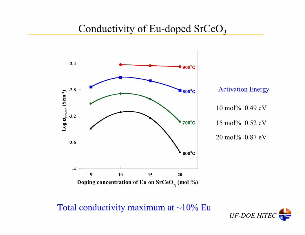
0.49 eV
0.52 eV
0.87 eV
10 mol%
15 mol%
20 mol%
Activation Energy
Total conductivity maximum at ~10% Eu
Conductivity of Eu-doped SrCeO3
Log
σPr
oton
(Scm
-1)

UF-DOE HiTEC
-4.5
-4
-3.5
-3
-2.5
-2
10 15 20
900oC
800oC
700oC
600oC
Doping concentration of Eu (mol %)
-4.5
-4
-3.5
-3
-2.5
-2
10 15 20
Doping concentration of Eu (mol %)
900oC
800oC
700oC
600oC
Proton Conductivity Electron Conductivity
Proton vs. Electron ConductivityL
og σ
Prot
on (S
cm-1
)
Log
σE
lect
ron (
Scm
-1)
Increasing Eu concentration:• Decreases σOH•• Increases σe’

UF-DOE HiTEC
0
0.2
0.4
0.6
0.8
1
600 700 800 900
Temperature (oC)
Proton [Eu10]
Proton [Eu15]
Proton [Eu20]
Electron [Eu10]
Electron [Eu15]
Electron [Eu20]
Increased Electronic Transference NumberTr
ansf
eren
ce n
umbe
r
!
tOH
O
• ="
OHO
•
"OH
O
• +" # e
t # e =
" # e
"OH
O
• +" # e
H2 flux limited by electronic conductivity

UF-DOE HiTEC
Conclusions• High temperature protonic conductors offer tremendous potential for
H2 production
• Adding electronic conductivity significantly increases H2 flux
• Demonstrated H2 permeation flux of ~10 cc/min– H2 flux is proportional to [PH2]1/4
– H2 flux is limited by electronic conduction
• Demonstrated pure H2 production from internal steam reformed CH4
• Demonstrated pure H2 production from water-gas-shift reaction– Increased H2 production of membrane reactor - La Chatlier
• Increasing Eu-dopant concentration will significantly increase H2permeation and production– Demonstrated >10X increase in te
– Should result in 6 liter/hr H2 production per tube

UF-DOE HiTEC
NASA Contract NAG3-2930DOE HiTEC Contract DE-AC05-76RL01830
Heesung YoonTakeun OhJianlin Li
Sun Ju SongJamie Rhodes
Acknowledgements
UF-DOE HiTEC
Hydrogen Production, Transport, and Storage 2
Abstracts should be submitted via the ECS website by January 3, 2007.
Comments and inquiries about the symposium may be sent to the organizers:E. D. Wachsman, University of Florida, [email protected]. C. Williams, NETL, [email protected]. Heben, NREL, [email protected]. Manivannan, NETL, [email protected]. P. Maupin, U.S. Department of Energy, [email protected]. V. Ramani, Illinois Institute of Technology, [email protected]
Symposium B4The Electrochemical Society
Chicago, May 6-11, 2007