hybrid-wing-body vehicle composite fuselage analysis and ... · hybrid-wing-body vehicle composite...
TRANSCRIPT
American Institute of Aeronautics and Astronautics
1
Hybrid-Wing-Body Vehicle Composite Fuselage Analysis and Case Study
Vivek Mukhopadhyay1
Aeronautical Systems Analysis Branch,
442/NASA Langley Research Center, Hampton, VA 23681
Abstract: Recent progress in the structural analysis of a Hybrid Wing-Body (HWB) fuselage concept is presented with the
objective of structural weight reduction under a set of critical design loads. This pressurized efficient HWB fuselage design is
presently being investigated by the NASA Environmentally Responsible Aviation (ERA) project in collaboration with the
Boeing Company, Huntington Beach. The Pultruded Rod-Stiffened Efficient Unitized Structure (PRSEUS) composite
concept, developed at the Boeing Company, is approximately modeled for an analytical study and finite element analysis.
Stiffened plate linear theories are employed for a parametric case study. Maximum deflection and stress levels are obtained
with appropriate assumptions for a set of feasible stiffened panel configurations. An analytical parametric case study is
presented to examine the effects of discrete stiffener spacing and skin thickness on structural weight, deflection and stress.
A finite-element model (FEM) of an integrated fuselage section with bulkhead is developed for an independent assessment.
Stress analysis and scenario based case studies are conducted for design improvement. The FEM model specific weight of
the improved fuselage concept is computed and compared to previous studies, in order to assess the relative weight/strength
advantages of this advanced composite airframe technology.
Nomenclature
a = spacing between y-directional stiffeners.
A = beam column cross section area.
Asx, Asy = section area of a single x-directional and y-directional stiffener, respectively.
b = spacing between x-directional stiffeners.
B = total breadth of stiffened panel between end supports.
D, Dx, Dy = bending rigidity of plate Et3/12(1 n
2).
Dx, Dy = bending rigidity of stiffened orthotropic plate about the y axis, and x axis, respectively.
Ex, Ey = Young’s modulus of orthotropic plate in x and y directions, respectively.
Ex, Ey = Young’s modulus of stiffeners in x and y directions, respectively
Fcx, Fcy = yield stress in compression along x and y directions, respectively.
Ftx, Fty = yield stress in tension along x and y directions, respectively.
g = acceleration due to gravity
G = shear modulus
I = area moment of inertia for beam bending about neutral axis.
Ix, Iy = area moment of inertia of x- and y-stiffeners about neutral axis, respectively.
L = total length of stiffened panel between end supports.
x, y = Possion’s ratio along x and y axis.
Mx, My = running bending moments about y and x axis, respectively (lbs.-inch/inch).
Nx, Ny = running in-plane load along x and y directions, respectively (lbs./inch).
Pc = axial compression load on beam-column.
Pcr = compression buckling load on beam-column.
P = cabin internal pressure of 9.2 psi (2P = 18.4 psi).
q = normal running load on beam or pressure on plate.
t = plate or base skin thickness.
w = beam or plate deflection, max at mid-point.
x, y = x and y reference axes of the plate or panel, respectively.
z = normal distance from beam or plate neutral plane.
Zox, Zoy = neutral axis location of x- and y-stiffeners from skin mid plane.
1 Senior Aerospace Engineer, Aeronautical Systems Analysis Branch, MS 442, AIAA Associate Fellow.
https://ntrs.nasa.gov/search.jsp?R=20140010063 2018-07-06T10:08:16+00:00Z
2
I. Introduction
Advanced composite fuselage configuration development for the Hybrid-Wing-Body1-3
(HWB) and Advanced Mobility
Concept4 flight vehicles are challenging compared to conventional tube and wing airframe technology. The standard stiffened
cylindrical fuselage is very efficient, since the skin is mostly under tensile membrane-hoop stress, when pressurized. The
streamlined HWB concept is aerodynamically more efficient, however the blended fuselage, with internal rectangular cross-
section airframe, is structurally inefficient. The internal cabin pressure combined with flight loads primarily result in highly
non-linear bending stresses and large deformations. The bending stresses due to the pressurization are theoretically one order
of magnitude higher5 than the membrane-hoop stress in a conventional cylindrical fuselage of similar size and skin thickness.
Moreover, resulting pillowing effects of the lifting fuselage surface could adversely affect aerodynamic performance
advantages provided by the streamlined blended fuselage and wing. Thus, it is necessary to design an efficient fuselage
structure in order to reduce the overall structural deflection, and weight penalty, while satisfying the design stress, strain, and
buckling safety factors, under the critical design loads. Many structural concepts such as the conventional skin-stringer-
frame, ribbed-double-shell, multi-bubble stiffened shell, thick sandwich, and Pultruded Rod Stitched Efficient Unitized
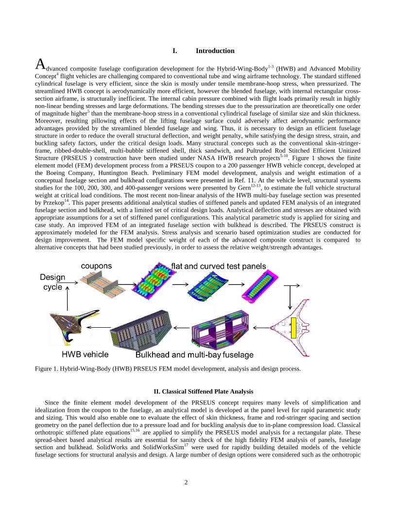
Structure (PRSEUS ) construction have been studied under NASA HWB research projects5-10
. Figure 1 shows the finite
element model (FEM) development process from a PRSEUS coupon to a 200 passenger HWB vehicle concept, developed at
the Boeing Company, Huntington Beach. Preliminary FEM model development, analysis and weight estimation of a
conceptual fuselage section and bulkhead configurations were presented in Ref. 11. At the vehicle level, structural systems
studies for the 100, 200, 300, and 400-passenger versions were presented by Gern12-13
, to estimate the full vehicle structural
weight at critical load conditions. The most recent non-linear analysis of the HWB multi-bay fuselage section was presented
by Przekop14
. This paper presents additional analytical studies of stiffened panels and updated FEM analysis of an integrated
fuselage section and bulkhead, with a limited set of critical design loads. Analytical deflection and stresses are obtained with
appropriate assumptions for a set of stiffened panel configurations. This analytical parametric study is applied for sizing and
case study. An improved FEM of an integrated fuselage section with bulkhead is described. The PRSEUS construct is
approximately modeled for the FEM analysis. Stress analysis and scenario based optimization studies are conducted for
design improvement. The FEM model specific weight of each of the advanced composite construct is compared to
alternative concepts that had been studied previously, in order to assess the relative weight/strength advantages.
Figure 1. Hybrid-Wing-Body (HWB) PRSEUS FEM model development, analysis and design process.
II. Classical Stiffened Plate Analysis
Since the finite element model development of the PRSEUS concept requires many levels of simplification and
idealization from the coupon to the fuselage, an analytical model is developed at the panel level for rapid parametric study
and sizing. This would also enable one to evaluate the effect of skin thickness, frame and rod-stringer spacing and section
geometry on the panel deflection due to a pressure load and for buckling analysis due to in-plane compression load. Classical
orthotropic stiffened plate equations15,16
are applied to simplify the PRSEUS model analysis for a rectangular plate. These
spread-sheet based analytical results are essential for sanity check of the high fidelity FEM analysis of panels, fuselage
section and bulkhead. SolidWorks and SolidWorksSim17
were used for rapidly building detailed models of the vehicle
fuselage sections for structural analysis and design. A large number of design options were considered such as the orthotropic
3
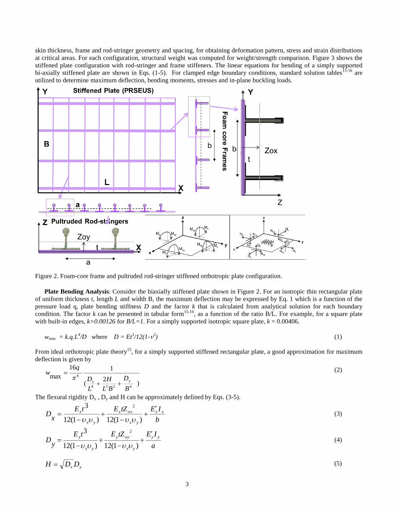
skin thickness, frame and rod-stringer geometry and spacing, for obtaining deformation pattern, stress and strain distributions
at critical areas. For each configuration, structural weight was computed for weight/strength comparison. Figure 3 shows the
stiffened plate configuration with rod-stringer and frame stiffeners. The linear equations for bending of a simply supported
bi-axially stiffened plate are shown in Eqs. (1-5). For clamped edge boundary conditions, standard solution tables15-16
are
utilized to determine maximum deflection, bending moments, stresses and in-plane buckling loads.
Figure 2. Foam-core frame and pultruded rod-stringer stiffened orthotropic plate configuration.
Plate Bending Analysis: Consider the biaxially stiffened plate shown in Figure 2. For an isotropic thin rectangular plate
of uniform thickness t, length L and width B, the maximum deflection may be expressed by Eq. 1 which is a function of the
pressure load q, plate bending stiffness D and the factor k that is calculated from analytical solution for each boundary
condition. The factor k can be presented in tabular form15-16
, as a function of the ratio B/L. For example, for a square plate
with built-in edges, k=0.00126 for B/L=1. For a simply supported isotropic square plate, k = 0.00406.
wmax = k.q.L4/D where D = Et
3/12(1-2
) (1)
From ideal orthotropic plate theory15
, for a simply supported stiffened rectangular plate, a good approximation for maximum
deflection is given by
)2
(
116
max
4224
6
B
D
BL
H
L
D
qw
yx
(2)
The flexural rigidity Dx , Dy and H can be approximately defined by Eqs. (3-5).
b
IEtZEtE
xD xx
yx
oxx
yx
x
)1(12)1(12
3 2
(3)
a
IEtZEtE
yD
yy
yx
oyy
yx
y
)1(12)1(12
3 2
(4)
(5) yx DDH
4
The terms Zox, Zoy, a and b in Eq.(3-5) are shown in Fig. 2. The equivalent plate rigidity Dx, Dy resists bending moment Mx,
My about the y- and x- axis, respectively. The attached longitudinal stiffening frames, each with area Asx and individual
bending stiffness ExIx move up the local neutral plane by Zox from the plate neutral (mid) plane, thereby increasing the total
area and the bending rigidity. The notation Ex is used to differentiate the stiffener elastic modulus from the plate elastic
modulus Ex. Similarly, the transverse rod-stringers, each with area Asy and bending stiffness EyIy, increase the plate flexural
rigidity Dy by moving up the section-area center by Zoy from the plate neutral plane.
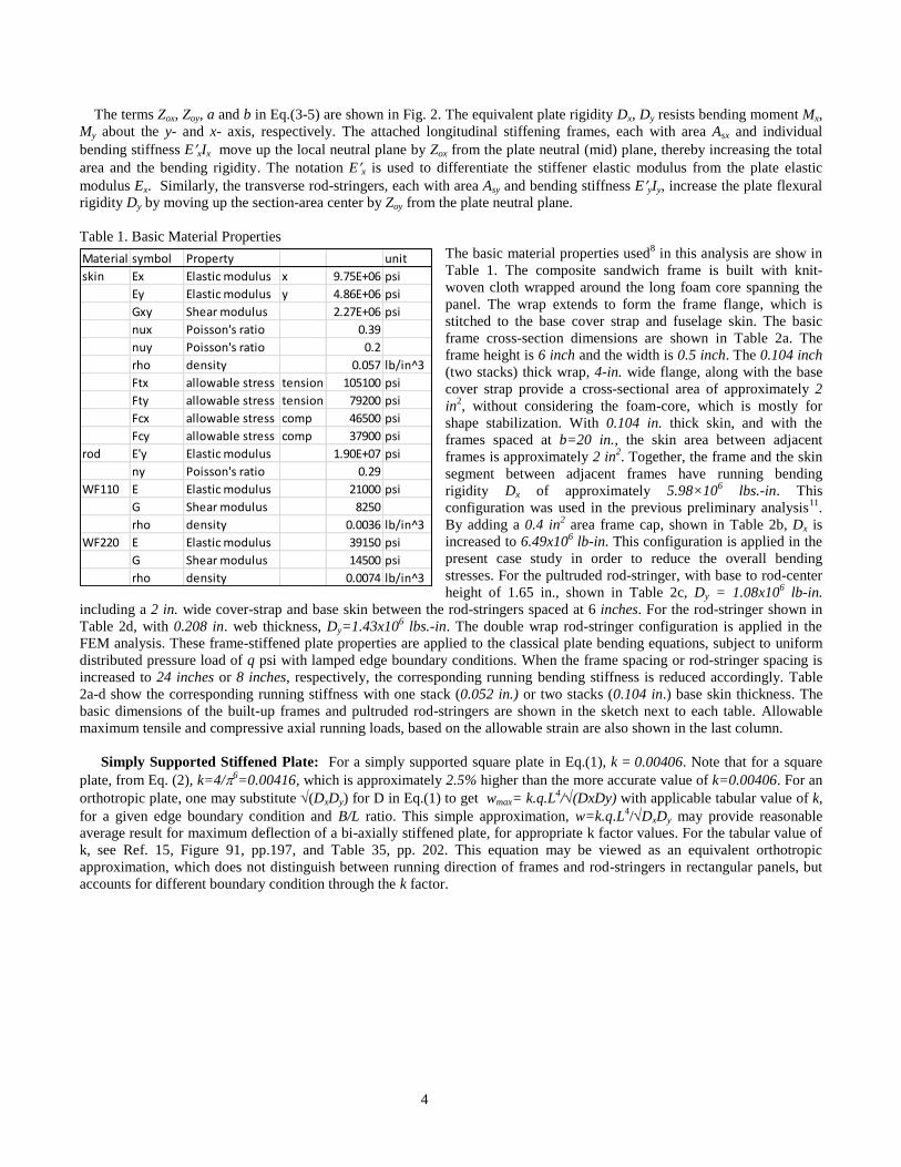
Table 1. Basic Material Properties
The basic material properties used8 in this analysis are show in
Table 1. The composite sandwich frame is built with knit-
woven cloth wrapped around the long foam core spanning the
panel. The wrap extends to form the frame flange, which is
stitched to the base cover strap and fuselage skin. The basic
frame cross-section dimensions are shown in Table 2a. The
frame height is 6 inch and the width is 0.5 inch. The 0.104 inch
(two stacks) thick wrap, 4-in. wide flange, along with the base
cover strap provide a cross-sectional area of approximately 2
in2, without considering the foam-core, which is mostly for
shape stabilization. With 0.104 in. thick skin, and with the
frames spaced at b=20 in., the skin area between adjacent
frames is approximately 2 in2. Together, the frame and the skin
segment between adjacent frames have running bending
rigidity Dx of approximately 5.98×10⁶ lbs.-in. This
configuration was used in the previous preliminary analysis11
.
By adding a 0.4 in2 area frame cap, shown in Table 2b, Dx is
increased to 6.49x10⁶ lb-in. This configuration is applied in the
present case study in order to reduce the overall bending
stresses. For the pultruded rod-stringer, with base to rod-center
height of 1.65 in., shown in Table 2c, Dy = 1.08x10⁶ lb-in.
including a 2 in. wide cover-strap and base skin between the rod-stringers spaced at 6 inches. For the rod-stringer shown in
Table 2d, with 0.208 in. web thickness, Dy=1.43x10⁶ lbs.-in. The double wrap rod-stringer configuration is applied in the
FEM analysis. These frame-stiffened plate properties are applied to the classical plate bending equations, subject to uniform
distributed pressure load of q psi with lamped edge boundary conditions. When the frame spacing or rod-stringer spacing is
increased to 24 inches or 8 inches, respectively, the corresponding running bending stiffness is reduced accordingly. Table
2a-d show the corresponding running stiffness with one stack (0.052 in.) or two stacks (0.104 in.) base skin thickness. The
basic dimensions of the built-up frames and pultruded rod-stringers are shown in the sketch next to each table. Allowable
maximum tensile and compressive axial running loads, based on the allowable strain are also shown in the last column.
Simply Supported Stiffened Plate: For a simply supported square plate in Eq.(1), k = 0.00406. Note that for a square
plate, from Eq. (2), k=4/6=0.00416, which is approximately 2.5% higher than the more accurate value of k=0.00406. For an
orthotropic plate, one may substitute (DxDy) for D in Eq.(1) to get wmax= k.q.L4/(DxDy) with applicable tabular value of k,
for a given edge boundary condition and B/L ratio. This simple approximation, w=k.q.L4/DxDy may provide reasonable
average result for maximum deflection of a bi-axially stiffened plate, for appropriate k factor values. For the tabular value of
k, see Ref. 15, Figure 91, pp.197, and Table 35, pp. 202. This equation may be viewed as an equivalent orthotropic
approximation, which does not distinguish between running direction of frames and rod-stringers in rectangular panels, but
accounts for different boundary condition through the k factor.
Material symbol Property unit
skin Ex Elastic modulus x 9.75E+06 psi
Ey Elastic modulus y 4.86E+06 psi
Gxy Shear modulus 2.27E+06 psi
nux Poisson's ratio 0.39
nuy Poisson's ratio 0.2
rho density 0.057 lb/in^3
Ftx allowable stress tension 105100 psi
Fty allowable stress tension 79200 psi
Fcx allowable stress comp 46500 psi
Fcy allowable stress comp 37900 psi
rod E'y Elastic modulus 1.90E+07 psi
ny Poisson's ratio 0.29
WF110 E Elastic modulus 21000 psi
G Shear modulus 8250
rho density 0.0036 lb/in^3
WF220 E Elastic modulus 39150 psi
G Shear modulus 14500 psi
rho density 0.0074 lb/in^3
5
(a)
(b)
(c)
(d)
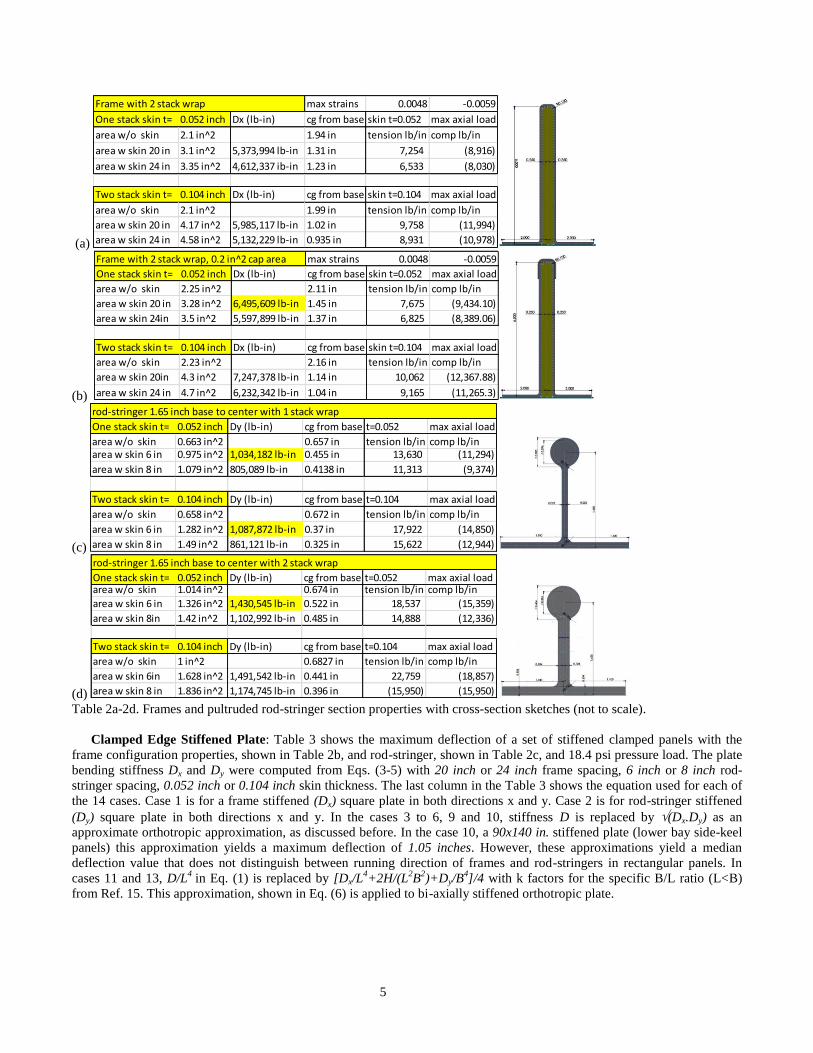
Table 2a-2d. Frames and pultruded rod-stringer section properties with cross-section sketches (not to scale).
Clamped Edge Stiffened Plate: Table 3 shows the maximum deflection of a set of stiffened clamped panels with the
frame configuration properties, shown in Table 2b, and rod-stringer, shown in Table 2c, and 18.4 psi pressure load. The plate
bending stiffness Dx and Dy were computed from Eqs. (3-5) with 20 inch or 24 inch frame spacing, 6 inch or 8 inch rod-
stringer spacing, 0.052 inch or 0.104 inch skin thickness. The last column in the Table 3 shows the equation used for each of
the 14 cases. Case 1 is for a frame stiffened (Dx) square plate in both directions x and y. Case 2 is for rod-stringer stiffened
(Dy) square plate in both directions x and y. In the cases 3 to 6, 9 and 10, stiffness D is replaced by (Dx.Dy) as an
approximate orthotropic approximation, as discussed before. In the case 10, a 90x140 in. stiffened plate (lower bay side-keel
panels) this approximation yields a maximum deflection of 1.05 inches. However, these approximations yield a median
deflection value that does not distinguish between running direction of frames and rod-stringers in rectangular panels. In
cases 11 and 13, D/L4
in Eq. (1) is replaced by [Dx/L4+2H/(L
2B
2)+Dy/B
4]/4 with k factors for the specific B/L ratio (L<B)
from Ref. 15. This approximation, shown in Eq. (6) is applied to bi-axially stiffened orthotropic plate.
Frame with 2 stack wrap max strains 0.0048 -0.0059
One stack skin t= 0.052 inch Dx (lb-in) cg from base skin t=0.052 max axial load
area w/o skin 2.1 in^2 1.94 in tension lb/in comp lb/in
area w skin 20 in 3.1 in^2 5,373,994 lb-in 1.31 in 7,254 (8,916)
area w skin 24 in 3.35 in^2 4,612,337 ib-in 1.23 in 6,533 (8,030)
Two stack skin t= 0.104 inch Dx (lb-in) cg from base skin t=0.104 max axial load
area w/o skin 2.1 in^2 1.99 in tension lb/in comp lb/in
area w skin 20 in 4.17 in^2 5,985,117 lb-in 1.02 in 9,758 (11,994)
area w skin 24 in 4.58 in^2 5,132,229 lb-in 0.935 in 8,931 (10,978)
Frame with 2 stack wrap, 0.2 in^2 cap area max strains 0.0048 -0.0059
One stack skin t= 0.052 inch Dx (lb-in) cg from base skin t=0.052 max axial load
area w/o skin 2.25 in^2 2.11 in tension lb/in comp lb/in
area w skin 20 in 3.28 in^2 6,495,609 lb-in 1.45 in 7,675 (9,434.10)
area w skin 24in 3.5 in^2 5,597,899 lb-in 1.37 in 6,825 (8,389.06)
Two stack skin t= 0.104 inch Dx (lb-in) cg from base skin t=0.104 max axial load
area w/o skin 2.23 in^2 2.16 in tension lb/in comp lb/in
area w skin 20in 4.3 in^2 7,247,378 lb-in 1.14 in 10,062 (12,367.88)
area w skin 24 in 4.7 in^2 6,232,342 lb-in 1.04 in 9,165 (11,265.3)
rod-stringer 1.65 inch base to center with 1 stack wrap
One stack skin t= 0.052 inch Dy (lb-in) cg from base t=0.052 max axial load
area w/o skin 0.663 in^2 0.657 in tension lb/in comp lb/inarea w skin 6 in 0.975 in^2 1,034,182 lb-in 0.455 in 13,630 (11,294)
area w skin 8 in 1.079 in^2 805,089 lb-in 0.4138 in 11,313 (9,374)
Two stack skin t= 0.104 inch Dy (lb-in) cg from base t=0.104 max axial load
area w/o skin 0.658 in^2 0.672 in tension lb/in comp lb/in
area w skin 6 in 1.282 in^2 1,087,872 lb-in 0.37 in 17,922 (14,850)
area w skin 8 in 1.49 in^2 861,121 lb-in 0.325 in 15,622 (12,944)
rod-stringer 1.65 inch base to center with 2 stack wrap
One stack skin t= 0.052 inch Dy (lb-in) cg from base t=0.052 max axial loadarea w/o skin 1.014 in^2 0.674 in tension lb/in comp lb/in
area w skin 6 in 1.326 in^2 1,430,545 lb-in 0.522 in 18,537 (15,359)
area w skin 8in 1.42 in^2 1,102,992 lb-in 0.485 in 14,888 (12,336)
Two stack skin t= 0.104 inch Dy (lb-in) cg from base t=0.104 max axial load
area w/o skin 1 in^2 0.6827 in tension lb/in comp lb/in
area w skin 6in 1.628 in^2 1,491,542 lb-in 0.441 in 22,759 (18,857)
area w skin 8 in 1.836 in^2 1,174,745 lb-in 0.396 in (15,950) (15,950)
6
)2
(
4
max
4224 B
D
BL
H
L
D
kqw
yx
(6)
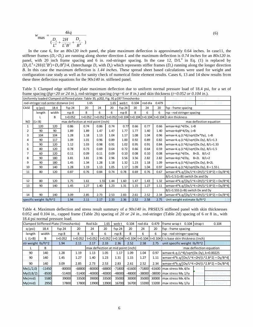
In the case 6, for an 80x120 inch panel, the plate maximum deflection is approximately 0.64 inches. In case11, the
stiffener frames (Dx>Dy) are running along shorter direction L and the maximum deflection is 0.74 inches for an 80x120 in.
panel, with 20 inch frame spacing and 6 in. rod-stringer spacing. In the case 12, D/L4 in Eq. (1) is replaced by
[Dy/L4+2H/(L
2B
2)+Dx/B
4]/4, (Interchange Dx with Dy) which represents stiffer frames (Dx) running along the longer direction
B. In this case the maximum deflection is 1.44 inches. These spread sheet based calculations were used for weight and
configuration case study as well as for sanity check of numerical finite element results. Cases 6, 13 and 14 show results from
these three deflection equations for the 90x140 in. stiffened panel.
Table 3. Clamped edge stiffened plate maximum deflection due to uniform normal pressure load of 18.4 psi, for a set of
frame spacing (fsp=20 or 24 in.), rod-stringer spacing (rsp=6 or 8 in.) and skin thickness (t=0.052 or 0.104 in.).
Table 4. Maximum deflection and stress result summary of a 90x140 in. PRSEUS stiffened panel with skin thicknesses
0.052 and 0.104 in., capped frame (Table 2b) spacing of 20 or 24 in., rod-stringer (Table 2d) spacing of 6 or 8 in., with
18.4 psi normal pressure load.
Uniformly loaded Clamped stiffened plate: Table 35, p202, Fig. 91 p197 Timoshenko fsp 20 rsp 6
rod-stringer rod center distance (in) 1.65 1.65 web t 0.104 rod dia 0.479 skin t 0.052 strap t 0.104
CASE q (psi) 18.4 fsp 24 20 24 20 fsp 24 20 24 20 fsp - frame spacing
length width rsp 8 8 6 6 rsp 8 8 6 6 rsp - rod stringer spacing
L B t=0.052 t=0.052 t=0.052 t=0.052 t=0.104 t=0.104 t=0.104 t=0.104 t skin thickness
NO (L< B) max deflection at mid point (inch) max deflection equation
1 120 120 0.86 0.74 0.86 0.74 0.77 0.66 0.77 0.66 wmax=kqL^4/Dx, L=B
2 90 90 1.89 1.89 1.47 1.47 1.77 1.77 1.40 1.40 wmax=kqB^4/Dy, L=B
3 104 104 1.28 1.18 1.13 1.04 1.17 1.08 1.04 0.96 wmax=k.q.(L^4)/sqrt(Dx*Dy), L=B
4 90 117 1.09 1.01 0.96 0.89 1.00 0.92 0.89 0.82 wmax=k.q.(L^4)/sqrt(Dx.Dy), B/L=1.3
5 90 120 1.12 1.03 0.98 0.91 1.02 0.95 0.91 0.84 wmax=k.q.(L^4)/sqrt(Dx.Dy), B/L=1.33
6 80 120 0.78 0.73 0.69 0.64 0.72 0.66 0.64 0.59 wmax=k.q.(L^4)/sqrt(Dx.Dy), B/L=1.5
7 60 120 0.11 0.09 0.11 0.09 0.10 0.08 0.10 0.08 wmax=kqL^4/Dx, B=2L B/L=2
8 90 180 3.81 3.81 2.96 2.96 3.56 3.56 2.82 2.82 wmax=kqL^4/Dy, B=2L B/L=2
9 90 180 1.45 1.34 1.28 1.18 1.32 1.23 1.18 1.09 wmax=k.q.(L^4)/sqrt(Dx.Dy), B=2L
10 90 140 1.28 1.19 1.13 1.05 1.17 1.09 1.04 0.97 wmax=k.q.(L^4)/sqrt(Dx.Dy), B = 1.55 L
11 80 120 0.87 0.76 0.84 0.74 0.78 0.69 0.76 0.67 wmax=4*k.q/[Dx/L^4 +2H/(L^2.B^2) + Dy/B^4]
B/L=1.5 (L<B) switch Dx and Dy
12 80 120 1.75 1.61 1.55 1.44 1.60 1.47 1.43 1.32 wmax=4*k.q/[Dy/L^4 +2H/(L^2.B^2) + Dx/B^4]
13 90 140 1.45 1.27 1.40 1.23 1.31 1.15 1.27 1.11 wmax=4*k.q/[Dx/L^4 +2H/(L^2.B^2) + Dy/B^4]
2.61 B/L=1.555 (L<B) switch Dx and Dy
14 90 140 3.09 2.85 2.73 2.53 2.83 2.61 2.52 2.34 wmax=4*k.q/[Dy/L^4 +2H/(L^2.B^2) + Dx/B^4]
specific weight lb/ft^2 1.94 2.11 2.17 2.33 2.36 2.52 2.58 2.75 Unit weight estimate lb/ft^2 2.33
Clamped Stiffened Plate (Timoshenko) Rod b2c 1.65 web t 0.104 rod dia 0.479 frame wrap t 0.104 strap t 0.104
q (psi) 18.4 fsp 24 20 24 20 fsp 24 20 24 20 fsp - frame spacing
length width rsp 8 8 6 6 rsp 8 8 6 6 rsp - rod stringer spacing
L (L<B) B t=0.052 t=0.052 t=0.052 t=0.052 t=0.104 t=0.104 t=0.104 t=0.104 t is base skin thickness (inch)
str weight lb/ft^2 1.94 2.11 2.17 2.33 2.36 2.52 2.58 2.75 unit specific weight lb/ft^2 2.33
L B max deflection at mid point (inch) max deflection equation
90 140 1.28 1.19 1.13 1.05 1.17 1.09 1.04 0.97 wmax=k.q.(L^4)/sqrt(Dx.Dy), B = 1.55 Lk=0.00225
90 140 1.45 1.27 1.40 1.23 1.31 1.15 1.27 1.11 wmax=4*k.q/[Dx/L^4 +2H/(L^2.B^2) + Dy/B^4]2.61 B/L=1.555 (L<B) switch Dx and Dy
90 140 3.09 2.85 2.73 2.53 2.83 2.61 2.52 2.34 wmax=4*k.q/[Dy/L^4 +2H/(L^2.B^2) + Dx/B^4]
Mx(L/2,0) -11450 -80000 -68800 -80000 -68800 -71800 -61600 -71800 -61600 max stress Mx.4/Ix -68746 Mx=-0.07685qL^2
My(0,B/2) -8500 -51400 -51400 -40000 -40000 -48000 -48000 -38000 -38000 max stress My.1/Iy -39986 My=-0.05705qL^2
Mx(mid) 5580 39000 33500 39000 33500 35000 30000 35000 30000 max stress Mx.4/Ix 33503 Mx=0.03745qL^2
My(mid) 2950 17800 17800 13900 13900 16700 16700 13200 13200 max stress My.1/Iy 13877 My=0.0198qL^2
7
Table 4 shows the specific weight, deflections and estimated local maximum stress values of a 90x140 in. PRSEUS
stiffened panel. Rows 2 to 4 show the set of frame spacing, rod-stringer spacing and skin thickness, which result in increasing
order of specific weight/unit pressurized surface area (row 4). The corresponding maximum deflections and bending stresses
due to the bending moments in the x and y directions at the mid-edge and center of the plate are also shown. The maximum
stress values are computed from the bending moment at mid-edge and center of the plate at the top of the capped frames and
rod-stringers. Pressure load is positive in the Z direction normal to the clamped panel. Hence, the maximum stresses are in
compression on the panel clamped-edge at the top of the frames. The bending stresses at mid-panel are in tension. This
scenario is similar to the loading condition on the bulkhead where frames and rod-stringers are located on the outer side of
the pressurized cabin. However, if internal cabin-pressure acts in the negative Z direction, like on the multi-bay cabin panels,
where frames and rod-stringers are built inside the fuselage, the stress situation may be reversed. The maximum stresses are
in tension on the panel clamped-edges at the top of the frames. The maximum bending stresses at the mid-panel are in
compression. The maximum stresses may locally exceed allowable compression stresses for the 18.4 psi pressure load. For
the 9.2 psi operational cabin pressure, the maximum stresses are within the allowable limits. Possible optimal combinations
are outlined in the Table 4. These two selections are; (a) 20 inch frame spacing, 6 inch rod-stringer spacing with 1 stack skin,
and (b) 24 inch frame spacing, 8 inch rod-stringer spacing with two stack skin. The case (b) is preferable due to better
damage tolerance, although the maximum deflection and specific weight is slightly higher for this case compared to that of
case (a). The maximum stresses are also higher in case (b).
Simply Supported Panel Buckling: Consider the simply supported stiffened plate in Fig. 2 under normal loading q and
in-plane compressive running load Nx, then the solution for deformation can be expressed approximately by
)2
(
116
max
224224
6
L
N
B
D
BL
H
L
D
qw
xyx
(7)
The value of the in-plane compressive running load Nx that renders the denominator of Eq. (7) to zero will provide the in-
plane buckling running load. Hence, the in-plane critical compressive buckling load Nxcr for the simply supported edge
condition is given by
Nxcr = 2L
2[Dx/L
4 + 2*H/(L
2.B
2) + Dy/B
4]. (8)
For the orthotropic rectangular plate with L=120 in., B=90 in., Dx = 6.5×10⁶ lb-in and Dy = 1.03×10
6 lb-in, the critical in-
plane running load Nxcr is 11,800 lbs./in. For an isotropic square plate, the critical minimum buckling is given by Nxcr =
42D/L
2. For a 104 x 104 in. square simply supported plate with D replaced by (DxDy), Nxcr = 8700 lbs./in.
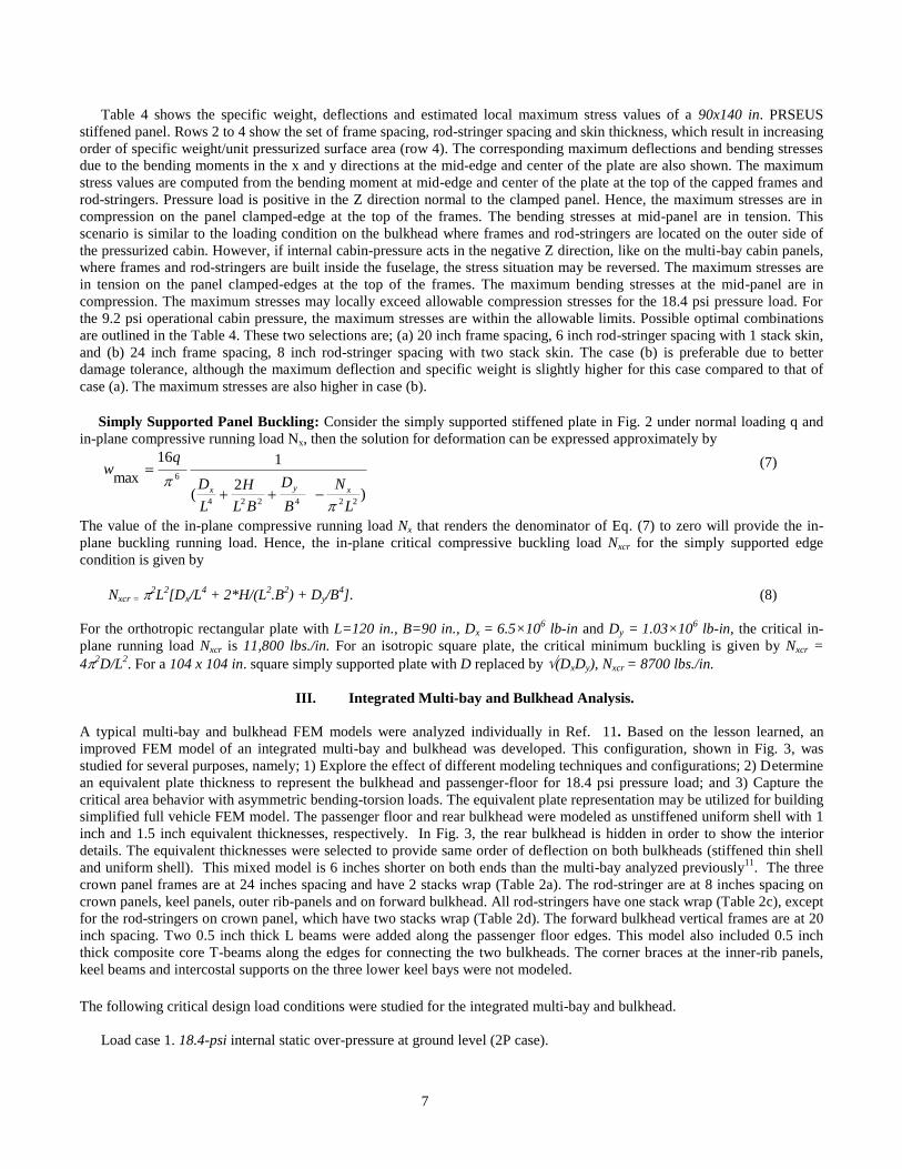
III. Integrated Multi-bay and Bulkhead Analysis.
A typical multi-bay and bulkhead FEM models were analyzed individually in Ref. 11. Based on the lesson learned, an
improved FEM model of an integrated multi-bay and bulkhead was developed. This configuration, shown in Fig. 3, was
studied for several purposes, namely; 1) Explore the effect of different modeling techniques and configurations; 2) Determine
an equivalent plate thickness to represent the bulkhead and passenger-floor for 18.4 psi pressure load; and 3) Capture the
critical area behavior with asymmetric bending-torsion loads. The equivalent plate representation may be utilized for building
simplified full vehicle FEM model. The passenger floor and rear bulkhead were modeled as unstiffened uniform shell with 1
inch and 1.5 inch equivalent thicknesses, respectively. In Fig. 3, the rear bulkhead is hidden in order to show the interior
details. The equivalent thicknesses were selected to provide same order of deflection on both bulkheads (stiffened thin shell
and uniform shell). This mixed model is 6 inches shorter on both ends than the multi-bay analyzed previously11
. The three
crown panel frames are at 24 inches spacing and have 2 stacks wrap (Table 2a). The rod-stringer are at 8 inches spacing on
crown panels, keel panels, outer rib-panels and on forward bulkhead. All rod-stringers have one stack wrap (Table 2c), except
for the rod-stringers on crown panel, which have two stacks wrap (Table 2d). The forward bulkhead vertical frames are at 20
inch spacing. Two 0.5 inch thick L beams were added along the passenger floor edges. This model also included 0.5 inch
thick composite core T-beams along the edges for connecting the two bulkheads. The corner braces at the inner-rib panels,
keel beams and intercostal supports on the three lower keel bays were not modeled.
The following critical design load conditions were studied for the integrated multi-bay and bulkhead.
Load case 1. 18.4-psi internal static over-pressure at ground level (2P case).
8
Load case 2. 2.5g climb condition with the cabin operational pressure of 9.2 psi (1P+2.5g case)
Load case 3. -1g dive condition with the cabin operational pressure of 9.2 psi (1P-1g case)
Load case 4. Buckling analysis at load cases 2 and 3 with additional asymmetric torsion load.
The maximum aerodynamic load for the 1P+2.5g case also produces a maximum compression load on the fuselage crown
panels and a maximum tensile load on the fuselage keel panels. This bending load is idealized as approximately 5000-lb/in.
running compression and tension load along the top and bottom panels, respectively. This in-plane ultimate design load was
derived from full-vehicle FEM analysis8,9,14
. In this linear analysis, the maximum allowable strain is 0.007 in tension and
0.0058 in compression on the stringer bulb areas. For the orthotropic skin and frame wraps, the allowable maximum strains
are assumed to be 0.0059 in tension and 0.0048 in compression.
Figure 3. Integrated multi-bay and bulkhead mixed model configuration.
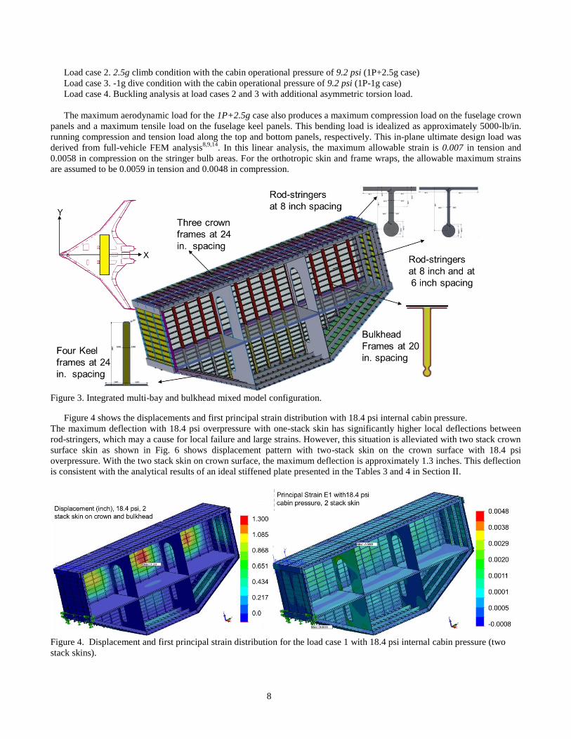
Figure 4 shows the displacements and first principal strain distribution with 18.4 psi internal cabin pressure.
The maximum deflection with 18.4 psi overpressure with one-stack skin has significantly higher local deflections between
rod-stringers, which may a cause for local failure and large strains. However, this situation is alleviated with two stack crown
surface skin as shown in Fig. 6 shows displacement pattern with two-stack skin on the crown surface with 18.4 psi
overpressure. With the two stack skin on crown surface, the maximum deflection is approximately 1.3 inches. This deflection
is consistent with the analytical results of an ideal stiffened plate presented in the Tables 3 and 4 in Section II.
Figure 4. Displacement and first principal strain distribution for the load case 1 with 18.4 psi internal cabin pressure (two
stack skins).
9
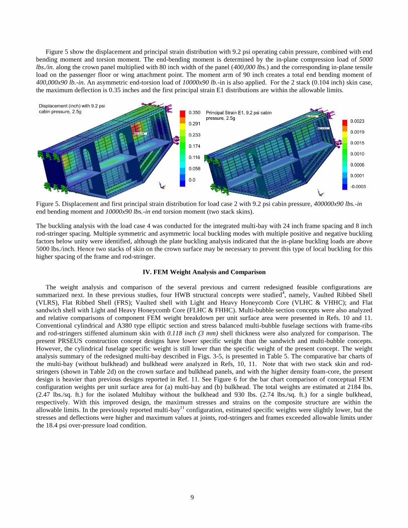
Figure 5 show the displacement and principal strain distribution with 9.2 psi operating cabin pressure, combined with end
bending moment and torsion moment. The end-bending moment is determined by the in-plane compression load of 5000
lbs./in. along the crown panel multiplied with 80 inch width of the panel (400,000 lbs.) and the corresponding in-plane tensile
load on the passenger floor or wing attachment point. The moment arm of 90 inch creates a total end bending moment of
400,000x90 lb.-in. An asymmetric end-torsion load of 10000x90 lb.-in is also applied. For the 2 stack (0.104 inch) skin case,
the maximum deflection is 0.35 inches and the first principal strain E1 distributions are within the allowable limits.
Figure 5. Displacement and first principal strain distribution for load case 2 with 9.2 psi cabin pressure, 400000x90 lbs.-in
end bending moment and 10000x90 lbs.-in end torsion moment (two stack skins).
The buckling analysis with the load case 4 was conducted for the integrated multi-bay with 24 inch frame spacing and 8 inch
rod-stringer spacing. Multiple symmetric and asymmetric local buckling modes with multiple positive and negative buckling
factors below unity were identified, although the plate buckling analysis indicated that the in-plane buckling loads are above
5000 lbs./inch. Hence two stacks of skin on the crown surface may be necessary to prevent this type of local buckling for this
higher spacing of the frame and rod-stringer.
IV. FEM Weight Analysis and Comparison
The weight analysis and comparison of the several previous and current redesigned feasible configurations are
summarized next. In these previous studies, four HWB structural concepts were studied4, namely, Vaulted Ribbed Shell
(VLRS), Flat Ribbed Shell (FRS); Vaulted shell with Light and Heavy Honeycomb Core (VLHC & VHHC); and Flat
sandwich shell with Light and Heavy Honeycomb Core (FLHC & FHHC). Multi-bubble section concepts were also analyzed
and relative comparisons of component FEM weight breakdown per unit surface area were presented in Refs. 10 and 11.
Conventional cylindrical and A380 type elliptic section and stress balanced multi-bubble fuselage sections with frame-ribs
and rod-stringers stiffened aluminum skin with 0.118 inch (3 mm) shell thickness were also analyzed for comparison. The
present PRSEUS construction concept designs have lower specific weight than the sandwich and multi-bubble concepts.
However, the cylindrical fuselage specific weight is still lower than the specific weight of the present concept. The weight
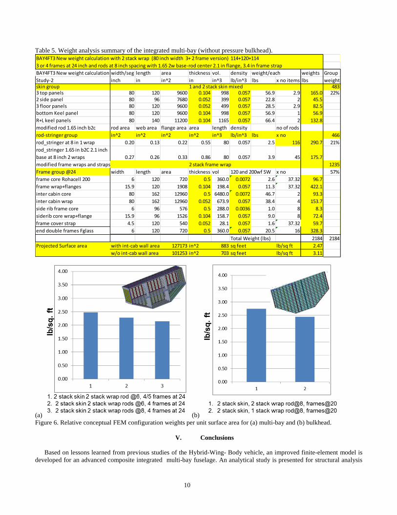
analysis summary of the redesigned multi-bay described in Figs. 3-5, is presented in Table 5. The comparative bar charts of
the multi-bay (without bulkhead) and bulkhead were analyzed in Refs, 10, 11. Note that with two stack skin and rod-
stringers (shown in Table 2d) on the crown surface and bulkhead panels, and with the higher density foam-core, the present
design is heavier than previous designs reported in Ref. 11. See Figure 6 for the bar chart comparison of conceptual FEM
configuration weights per unit surface area for (a) multi-bay and (b) bulkhead. The total weights are estimated at 2184 lbs.
(2.47 lbs./sq. ft.) for the isolated Multibay without the bulkhead and 930 lbs. (2.74 lbs./sq. ft.) for a single bulkhead,
respectively. With this improved design, the maximum stresses and strains on the composite structure are within the
allowable limits. In the previously reported multi-bay11
configuration, estimated specific weights were slightly lower, but the
stresses and deflections were higher and maximum values at joints, rod-stringers and frames exceeded allowable limits under
the 18.4 psi over-pressure load condition.
10
Table 5. Weight analysis summary of the integrated multi-bay (without pressure bulkhead).
(a) (b)
Figure 6. Relative conceptual FEM configuration weights per unit surface area for (a) multi-bay and (b) bulkhead.
V. Conclusions
Based on lessons learned from previous studies of the Hybrid-Wing- Body vehicle, an improved finite-element model is
developed for an advanced composite integrated multi-bay fuselage. An analytical study is presented for structural analysis
BAY4FT3 New weight calculation with 2 stack wrap (80 inch width 3+ 2 frame version) 114+120+114
3 or 4 frames at 24 inch and rods at 8 inch spacing with 1.65 2w base-rod center 2.1 in flange, 3.4 in frame strap
BAY4FT3 New weight calculation with 2 stack wrap (80 inch width 3+ 2 frame version)width/seg length area thickness vol. density weight/each weights Group
Study-2 inch in in^2 in in^3 lb/in^3 lbs x no items lbs weightskin group 1 and 2 stack skin mixed 4833 top panels 80 120 9600 0.104 998 0.057 56.9 2.9 165.0 22%2 side panel 80 96 7680 0.052 399 0.057 22.8 2 45.53 floor panels 80 120 9600 0.052 499 0.057 28.5 2.9 82.5
bottom Keel panel 80 120 9600 0.104 998 0.057 56.9 1 56.9
R+L keel panels 80 140 11200 0.104 1165 0.057 66.4 2 132.8
modified rod 1.65 inch b2c rod area web area flange area area length density no of rods
rod-stringer group in^2 in^2 in^2 in^2 in^3 lb/in^3 lbs x no 466
rod_stringer at 8 in 1 wrap 0.20 0.13 0.22 0.55 80 0.057 2.5 116 290.7 21%
rod_stringer 1.65 in b2C 2.1 inch
base at 8 inch 2 wraps 0.27 0.26 0.33 0.86 80 0.057 3.9 45 175.7
modified frame wraps and straps 2 stack frame wrap 1235
Frame group @24 width length area thickness vol 120 and 200wf SW x no 57%
frame core Rohacell 200 6 120 720 0.5 360.0 0.0072 2.6 37.32 96.7
frame wrap+flanges 15.9 120 1908 0.104 198.4 0.057 11.3 37.32 422.1
inter cabin core 80 162 12960 0.5 6480.0 0.0072 46.7 2 93.3
inter cabin wrap 80 162 12960 0.052 673.9 0.057 38.4 4 153.7
side rib frame core 6 96 576 0.5 288.0 0.0036 1.0 8 8.3
siderib core wrap+flange 15.9 96 1526 0.104 158.7 0.057 9.0 8 72.4
frame cover strap 4.5 120 540 0.052 28.1 0.057 1.6 37.32 59.7
end double frames Fglass 6 120 720 0.5 360.0 0.057 20.5 16 328.3
Total Weight (lbs) 2184 2184
Projected Surface area with int-cab wall area 127173 in^2 883 sq feet lb/sq ft 2.47
w/o int-cab wall area 101253 in^2 703 sq feet lb/sq ft 3.11
11
of a composite stiffened panel under 18.4 psi normal pressure. A rational case study is performed to determine the effect of
feasible skin-thickness, rod-stringer spacing and frame spacing options on the maximum deflection, stress levels and
structural weight and to improve the overall design. A set of critical design load conditions are examined. From the analysis
of a multi-bay finite element model, it is concluded that two stack skin laminates will be necessary to improve overall safety
margins and impact damage resistance. Two-stack skin would allow slightly higher stiffener spacing of 8 inches to minimize
the weight penalty. Two-stack frame-wraps with additional frame caps are recommended to reduce the local strain levels. In
addition, reinforced two-stack wrap rod-stringers on the crown surface are applied to reduce the stress level at the 18.4 psi
over-pressure condition. Although, local buckling concerns remain at the maximum climb load conditions, the stitched
composite structure can carry load in the post buckling condition. The adverse aerodynamic effects due the outer-surface
pillowing at operational cabin pressure still remain a concern and need to be analyzed. Analysis of the composite bi-axially
stiffened shell concept demonstrated that the hybrid-wing-body class of vehicles can be structurally as efficient as the
conventional cylindrical skin-stringer-frame construction. However, alternate concepts such as foam-core hat-stringer should
also be considered to address the manufacturing and repair issues. With continuing development, the advanced composite
technology has the potential to render the current hybrid-wing-body concept both structurally feasible and aerodynamically
efficient.
VI. Acknowledgments
This research was sponsored by the NASA Environmentally Responsible Aviation (ERA) Project in collboration with the
Boeing Company, Huntington Beach. The author wishes to thank Dr. Fayette Collier, Project Manager, ERA Project; Dr.
Anthony Washburn, Project Engineer; Pamela Davis, Assoc. Project Manager, Airframe Technology, William Kimmel,
Chief Technologist, Systems Analysis and Concepts Directorate, Dr. Mike Marcolini, Branch Head, and Dr. Frank Gern,
Assistant Branch Head (Acting), Aeronautical Systems Analysis Branch; as well as the Aeronautics Research Mission
Directorate for funding this project. Technical discussion and guidance from Alex Velicki, Dawn Jegley, Craig Nickol and
Andrew Lovejoy are greatly appreciated.
VII. References
1
Liebeck, R. H., Page, M. A., and Rawdon, B. K., “Blended-Wing-Body Subsonic Commercial Transport,” AIAA Paper
1998-0438, January 1998. 2
Mukhopadhyay, V., “Structural Concepts Study of Non-circular Fuselage Configurations,” Paper No. AIAA SAE WAC-67,
World Aviation Congress, Los Angeles, Calif. Oct. 22-24, 1996. 3
Liebeck, R. H, “Design of the Blended Wing Body Subsonic Transport,” Journal of Aircraft, Vol. 41, No. 1, Jan-Feb. 2004,
pp. 10-25. 4
Hoffman, K., “Air Vehicle Technology Integration Program (AVTIP), Multi-role Bomber Structural Analysis, AFRL-VA-
WP-TR-2006-3067, May 2006, Final Report for 14 December 2004–May 2006, AFRL-VA-WP-TR-2006-3067. 5
Mukhopadhyay, V., Sobieszczanski-Sobieski, J., Kosaka, I., Quinn, G., and Vanderplaats, G., “Analysis, Design and
Optimization of Non-cylindrical Fuselage for Blended-Wing-Body Vehicle,” Journal of Aircraft, Vol. 41, No. 4, July-
August, 2004, pp. 925-930. 6
Velicki, A., and Thrash, P. J., “Advanced Structural Concept Development Using Stitched Composites,” The Boeing
Company, Huntington Beach, California 92647-2099, AIAA Paper 2008-2329. 7
Velicki, A., Thrash, P. J., and Jegley, D., “Airframe Development for the Hybrid Wing Body Aircraft,” AIAA Paper 2009-
932. 8
Velicki, A., Yovanof, N., Baraja, J., Linton, K., Li, V., Hawley, A., Thrash, P., DeCoux, S., and Pickell, R., “Damage
Arresting Composites for Shaped Vehicles-Phase II Final Report, NASA/CR 2011-216880, 2011. 9
Wu, H., and Shaw, P., “Analysis of a Hybrid Wing Body Center Section Test Article”, AIAA Paper 2013-1734: 54th
AIAA/ASME/ASCE/AHS/ASC Structures, Structural Dynamics, and Materials Conference, Boston, April 2013. 10
Mukhopadhyay, V: “Hybrid Wing-Body Pressurized Fuselage Modeling, Analysis, and Design for Weight Reduction,”
AIAA Paper 2012-1999, 53rd AIAA/ASME/ASCE/AHS/ASC Structures, Structural Dynamics, and Materials Conference,
Honolulu, April 2012. 11
Mukhopadhyay, V: “Hybrid Wing-Body Pressurized Fuselage and Bulkhead Design and Optimization,” AIAA Paper 2013-
1717, 54th AIAA/ASME/ASCE/AHS/ASC Structures, Structural Dynamics, and Materials Conference, Boston, April
2013.
12
12 Gern, F. H., “Finite Element Based HWB Centerbody Structural Optimization and Weight Prediction, AIAA Paper 2012-
1606, April 2012. 13 Gern, F., “Conceptual Design and Structural Analysis of an Open Rotor Hybrid Wing Body Aircraft,” AIAA Paper 2013-
1688: 54th AIAA/ASME/ASCE/AHS/ASC Structures, Structural Dynamics, and Materials Conference, Boston, April
2013. 14
Przekop, A., Wu, H. T., Shaw, P., “Nonlinear Finite Element Analysis of a Composite Non-Cylindrical Pressurized
Aircraft Fuselage Structure,” AIAA-2014-1064, 55th AIAA/ASME/ASCE/AHS/ASC Structures, Structural Dynamics, and
Materials Conference, National Harbor, MD, January 2014. 15
Timoshenko, S., and Krieger, S.W., “Theory of Plates and Shells,” McGraw-Hill, New York, 2nd
Edition, 1959, pp.197-202. 16
Timoshenko, S., and Geer, J.M, “Theory of Elastic Stability,” McGraw-Hill, New York, Reprinted by Dover, New York, 2nd
Edition, 1989, pp.1-45, pp.362-367. 17
SolidWorks and SolidWorks Simulation User Manual 2011, SolidWorks Corporation, Dassault Systèmes, Concord,
Massachusetts.