hybrid pump storage hydro power plant: site selection
TRANSCRIPT

1
Hybrid Pump Storage Hydro Power Plant:
Site Selection, Economic Analysis and Water Hammer Calculation
Helmut Benigni, Helmut Jaberg and Stefan Höller,
Graz University of Technology, Austria
ABSTRACT
The technology provided by pumped storage plants is the only technology available to store power on a large scale. Hence, for the integration of a wind turbine park into the small existing grid on an isolated island the licensor is obliged to operate a pumped storage plant in combination with water, wind and photovoltaic power units – generally referred to as hybrid power plant.
For such a pumped-storage hydro power plant the grid and wind situation have been analyzed over a two years period, and on the basis of the data acquired, an environmentally compatible plant has been developed by means of turbine and pump analysis, construction plans, analysis of the power supply and the dimensioning of the upper and lower reservoirs. In order to answer all licensing requirements with taking into account all wind regimes possible and for the purpose of an economic evaluation, numerous operation modes have been analyzed. Water hammer analysis has been realized for the dimensioning of the pressure pipe and for the final definition of the plant concept.
The capacity of the pumped storage plant had to be designed in such a manner that regardless of any and all imaginable wind or solar regimes – whether advantageous and/or disadvantageous – the capacity and the power supply are guaranteed, whereas the plant should be operated as profitably as possible. A head difference of 550 m is characteristic for the location analyzed.
Introduction – Approach
In isolated grids with a large portion of unreliable energy generation institutions the integration of wind power plants is hardly feasible. Also, storage facilities which allow for compensation of fluctuations in grid load between day and night are required, as otherwise the total machine unit would have to be designed for peak load, yet would quite often be operated in part load – the problems and disadvantages of part-load operation being widely known.
In fact, the technology provided by pumped storage plants is the only technology available to store power on a large scale. Hence, for the integration of a wind turbine park into the small existing grid on an isolated island the licensor is obliged to operate a pumped storage plant in combination with water, wind and photovoltaic power units – generally referred to as hybrid power plant.
This research concentrates on the pump storage plant, whereas wind power has only a passive impact as of the temporal fluctuations of wind strength and thus varying generation of wind power – although the corresponding values are necessary. These fluctuations are not predictable, yet the capacity and the power required by the licensor have to be ensured round the clock (24/7). So, regardless of any and all imaginable wind regimes – whether advantageous and/or disadvantageous the capacity of the pump storage plant has to be designed in a way to guarantee the capacity and the power supply required. At the same time plant operation should be as profitable as possible. It has to be considered that a head difference of 550 m is characteristic for the location analyzed and that the immediate surroundings allow for the installation of wind turbines. The design project for the storage system of the power plant provides two storage reservoirs (see Figure 1 with upper and lower reservoir), a pump building, a separate turbine power house, a pipeline system and the necessary connections between the single components. Furthermore, the power plant itself will be integrated into a small existing grid on an isolated island. Similar projects are presented in [3] to [6].
The project licensee has been granted a general economic framework, with the latter providing for a compensation scheme adapted to the present standards, which – to some extent – are also

2
mentioned in [1] or [2]. The licensor requires that the hybrid power plant provides a capacity of 5 MW for 8 optional hours every single day of the year – regardless of the wind regime. Power can be purchased from other suppliers if applicable, e.g. in case of weak wind or in case water has to be pumped. The guaranteed price for the MWh generated by means of water power is 100%, the price for pump power purchased amounts to 79% – so the spread is rather small. Also, the guaranteed purchase price for a wind power MWh is 54%. Provision of capacities is going to be paid separately.
(a) Plan view
Upper
reservoir
Lower reservoir(b) Vertical section
Pump building
Power house
(c) Numerical
model
GRP pipe,
L=940,5mSteel pipe,
L=869m
4 to 8
pumps
2-3 turbines
Figure 1. Plan and vertical view of the hydro power plant, numerical model
Operation modes
Based on the license, the following operation modes are possible:
1. Wind energy (REP) used for 100% pumping.
2. Wind energy and turbine energy, both fed into the grid.
3. Only wind energy is fed into the grid.
4. Combination of the above-mentioned modes.
5. Hydraulic shortcut for free power regulation in pump mode. Although this operation mode is not part of the license, it is an additional must for the customer.
Figure 2 presents a schematic illustration of two different operation modes. The top picture shows pumps with power fully generated of wind energy, so without the purchase of additional power from the grid and without power supply to the grid. The bottom picture shows the load case of full turbine operation in calm conditions. As the grid disposes of adequate energy reserves, the pumps can be operated with grid power only.

3
M M M M
G G G
upper
reservoir
lower
reservoir
Operation mode 01: 100 % pump, 0% turbine, 100% windturbine
100 % (5.1 MW)
100 % (5.1 MW)0 % (0 MW)
750 l/s
750 l/s
0 l/s
0 %
(0 MW)
Full pumping mode via wind turbines, no turbine mode (no power production)
MM
Figure 2. Examples of operation modes for the planned hybrid power plant. Top: 100% wind power used for pump mode, bottom: 100% turbine mode
Wind conditions
The wind and electrical grid conditions have to be analyzed in detail to choose the appropriate machine layout which has to comply with all terms of the license. For this purpose, data on wind conditions collected for a nearby wind park (at a distance of 20 km to the plant location) were provided. Based on these highly reliable wind data an analysis was realized. The data for eleven wind turbines (type Vestas V52) were recorded at 10-minute intervals. The performance of this wind park, operated for 5 years already, is representative for the wind conditions in this region.
Based on the data collected for the eleven wind turbines, an arithmetic mean was calculated
(nominal performance/capacity per wind turbine 850 kW) and then translated into the value of the
site planned – as mean value for one month in the course of one day. As shown in Figure 3, a
period of lower energy production can be seen for the morning hours. However, it is quite evident
that the mean value for all days of a year provides absolutely no guarantee that all license terms are
met under all wind conditions. Obviously, this fact becomes problematic in the event of long-lasting
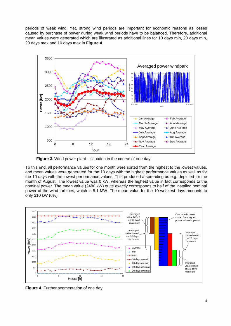
4
periods of weak wind. Yet, strong wind periods are important for economic reasons as losses
caused by purchase of power during weak wind periods have to be balanced. Therefore, additional
mean values were generated which are illustrated as additional lines for 10 days min, 20 days min,
20 days max and 10 days max in Figure 4.
500
1000
1500
2000
2500
3000
3500
0 6 12 18 24
Po
we
r [k
W]
hour
Jan Average Feb Average
March Average April Average
May Average June Average
July Average Aug Average
Sept Average Oct Average
Nov Average Dec Average
Year Average
Rovas wind park, averaged power
0
100
200
300
400
500
600
700
800
01.01.2010 01.01.2011
Time
Po
we
r [k
W]
Averaged power windpark
Figure 3. Wind power plant – situation in the course of one day
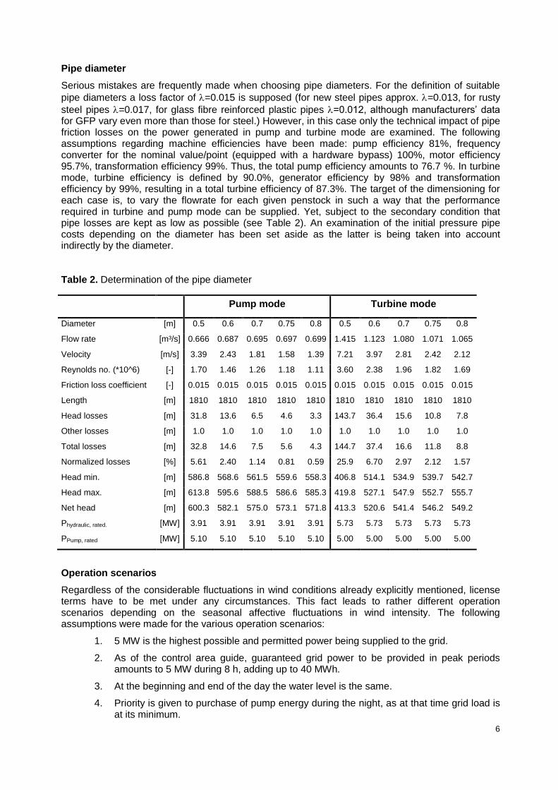
To this end, all performance values for one month were sorted from the highest to the lowest values, and mean values were generated for the 10 days with the highest performance values as well as for the 10 days with the lowest performance values. This produced a spreading as e.g. depicted for the month of August. The lowest value was 0 kW, whereas the highest value in fact corresponds to the nominal power. The mean value (2480 kW) quite exactly corresponds to half of the installed nominal power of the wind turbines, which is 5.1 MW. The mean value for the 10 weakest days amounts to only 310 kW (6%)!
August, Wind Power
0
500
1000
1500
2000
2500
3000
3500
4000
4500
5000
5500
0 6 12 18 24
Hours
Po
wer
[kW
]
Average
Min
Max
10 days ave min
20 days ave min
10 days ave max
20 days ave max
August, Wind Power
0
500
1000
1500
2000
2500
3000
3500
4000
4500
5000
5500
0 6 12 18 24
Hours
Po
wer
[kW
]
Average
Min
Max
10 days ave min
20 days ave min
10 days ave max
20 days ave max
averaged
value based
on 20 days
minimum
averaged
value based
on 10 days
minimum
averaged
value based
on 20 days
maximum
averaged
value based
on 10 days
maximum
One month, power
sorted from highest
power to lowest power
Hours [h]
Po
we
r [k
W]
Figure 4. Further segmentation of one day

5
Grid situation
For the years 2007 and 2008 an analysis of the grid load was performed, providing data in 15-minute intervals. Figure 5 shows an overview with a minimum of approximately 100 MW and a six-fold maximum value. The target of this analysis was, to define time periods for the technically most favorable power purchase in periods of weak grid load.
100
200
300
400
500
600
700
800
0 1 2 3 4 5 6 7 8 9 10 11 12 13 14 15 16 17 18 19 20 21 22 23
Po
we
r [M
W]
Hour
average Jan average Feb average March
average April average May average June
average July average Aug average Sept
average Oct average Nov average Dec
average Year
Figure 5. Grid situation on an isolated island
Generally, in July and August consumption is at its highest level, followed by June and September. However, the fluctuations occurring in the course of one day are also rather significant. Figure 5 shows the distribution for all twelve months of a year and apparently daily demand fluctuates by the factor 2. In order to guarantee reliable operation, it was assumed that for each day of the scenarios described hereinafter the water level at 00:00 has to be the same as the preceding day, resulting in the maximum operation data as of Table 1 and the volumes for tailwater and headwater in the magnitude order displayed. These values are based on a turbine flowrate of 1.1 m³/s, which is necessary for the production of turbine power with the penstock given at license conditions, and a guaranteed power production of 16 hours within two days (thus meeting the license terms). With a bullet point of 00:00 and a serve volume of 2 h, the total volume round-up amounts to 75.000 m³. Assuming that the nominal pump flowrate is 0.75 m³/s, turbine mode operation is potentially possible for 9.73 h followed by 14.27 h pump mode in order to keep the water level at the level of the previous day.
Table 1. Hydro power plant main data
Turbine flowrate for nominal power [m³/s] 1.1
Hours of turbine mode (2 days, each 8h) [h] 16
Volume for regular operation [m³] 63360
Reserve (has to be provided all the time) [h] 2
Volume for reserve [m³] 7920
Total volume [m³] 71280
Total volume round-up (evaporation a.o.) [m³] 75000
Pump flowrate for nominal power [m³/s] 0.75
Factor pump/turbine [-] 1.466667
6
Pipe diameter
Serious mistakes are frequently made when choosing pipe diameters. For the definition of suitable
pipe diameters a loss factor of =0.015 is supposed (for new steel pipes approx. =0.013, for rusty
steel pipes =0.017, for glass fibre reinforced plastic pipes =0.012, although manufacturers’ data for GFP vary even more than those for steel.) However, in this case only the technical impact of pipe friction losses on the power generated in pump and turbine mode are examined. The following assumptions regarding machine efficiencies have been made: pump efficiency 81%, frequency converter for the nominal value/point (equipped with a hardware bypass) 100%, motor efficiency 95.7%, transformation efficiency 99%. Thus, the total pump efficiency amounts to 76.7 %. In turbine mode, turbine efficiency is defined by 90.0%, generator efficiency by 98% and transformation efficiency by 99%, resulting in a total turbine efficiency of 87.3%. The target of the dimensioning for each case is, to vary the flowrate for each given penstock in such a way that the performance required in turbine and pump mode can be supplied. Yet, subject to the secondary condition that pipe losses are kept as low as possible (see Table 2). An examination of the initial pressure pipe costs depending on the diameter has been set aside as the latter is being taken into account indirectly by the diameter.
Table 2. Determination of the pipe diameter
Pump mode Turbine mode
Diameter [m] 0.5 0.6 0.7 0.75 0.8 0.5 0.6 0.7 0.75 0.8
Flow rate [m³/s] 0.666 0.687 0.695 0.697 0.699 1.415 1.123 1.080 1.071 1.065
Velocity [m/s] 3.39 2.43 1.81 1.58 1.39 7.21 3.97 2.81 2.42 2.12
Reynolds no. (*10^6) [-] 1.70 1.46 1.26 1.18 1.11 3.60 2.38 1.96 1.82 1.69
Friction loss coefficient [-] 0.015 0.015 0.015 0.015 0.015 0.015 0.015 0.015 0.015 0.015
Length [m] 1810 1810 1810 1810 1810 1810 1810 1810 1810 1810
Head losses [m] 31.8 13.6 6.5 4.6 3.3 143.7 36.4 15.6 10.8 7.8
Other losses [m] 1.0 1.0 1.0 1.0 1.0 1.0 1.0 1.0 1.0 1.0
Total losses [m] 32.8 14.6 7.5 5.6 4.3 144.7 37.4 16.6 11.8 8.8
Normalized losses [%] 5.61 2.40 1.14 0.81 0.59 25.9 6.70 2.97 2.12 1.57
Head min. [m] 586.8 568.6 561.5 559.6 558.3 406.8 514.1 534.9 539.7 542.7
Head max. [m] 613.8 595.6 588.5 586.6 585.3 419.8 527.1 547.9 552.7 555.7
Net head [m] 600.3 582.1 575.0 573.1 571.8 413.3 520.6 541.4 546.2 549.2
Phydraulic, rated. [MW] 3.91 3.91 3.91 3.91 3.91 5.73 5.73 5.73 5.73 5.73
PPump, rated [MW] 5.10 5.10 5.10 5.10 5.10 5.00 5.00 5.00 5.00 5.00
Operation scenarios
Regardless of the considerable fluctuations in wind conditions already explicitly mentioned, license terms have to be met under any circumstances. This fact leads to rather different operation scenarios depending on the seasonal affective fluctuations in wind intensity. The following assumptions were made for the various operation scenarios:
1. 5 MW is the highest possible and permitted power being supplied to the grid.
2. As of the control area guide, guaranteed grid power to be provided in peak periods amounts to 5 MW during 8 h, adding up to 40 MWh.
3. At the beginning and end of the day the water level is the same.
4. Priority is given to purchase of pump energy during the night, as at that time grid load is at its minimum.

7
Based on the wind park data referring to the average monthly wind intensity (see Figure 6, pink, partially behind the red line), a 24h scenario for one whole day has been developed for each month. The grey curves stand for the mean values of 10 days minimum/maximum. Furthermore, a mean value has been generated for the electrical grid, which is displayed in yellow.
0
100
200
300
400
500
600
0
1
2
3
4
5
6
0 6 12 18 24
Lo
ad
Cre
te [
MW
]
Po
we
r [M
W]
DAY
Scenario August
Power from REP Total power for pumping Guar. power from turbine Total guar. power
Power from grid for pumping 10 days ave min 20 days ave min 10 days ave max
20 days ave max Creta Load [MW]
Figure 6. Example scenario August – mean value
0
100
200
300
400
500
600
0
1
2
3
4
5
6
0 6 12 18 24
Lo
ad
Cre
te [
MW
]
Po
we
r [M
W]
DAY
Scenario August, 10 days min
Power from REP Total power for pumping Guar. power from turbine Total guar. power
Power from grid for pumping 10 days ave min 20 days ave min 31 days ave
10 days ave max 20 days ave max Creta Load [MW]
Figure 7. Example scenario August – 10 days minimum
8
In accordance with the grid load, the assumption for this sample month was, that the control area guide triggers the power in two blocks of 5 respectively 3 hours. The blue curve shows the power generation with turbines, for a total period of 8 hours. The brown curve depicts the additional requirement of grid energy for the pump mode during weak wind periods, which, however, in Figure 6 always remains zero as, with the monthly wind average, there is sufficient wind power for the pump mode.
The same procedure was applied for the minimum mean value of the ten weakest days – for details see Figure 7. In this scenario high amounts of pump energy have to be covered by means of maximum pump performance during the night, of course at maximum exploitation of the self-generated wind power. The high demand in pump energy results of the fact, that during weak wind periods turbine mode is predominant in order to meet license requirements for power production. Hence, water consumption is high, and the necessary water has to be pumped in advance. And that is why under weak wind circumstances like these the purchase of high volumes of expensive grid power is inevitable. A stretching of wind power to higher performance values installed could be a solution for this dilemma, however, it would also require a new license evaluation. Based on the above-described scenarios, an evaluation of the economic efficiency can be realized – its results being fortunately positive.
Water hammer calculation
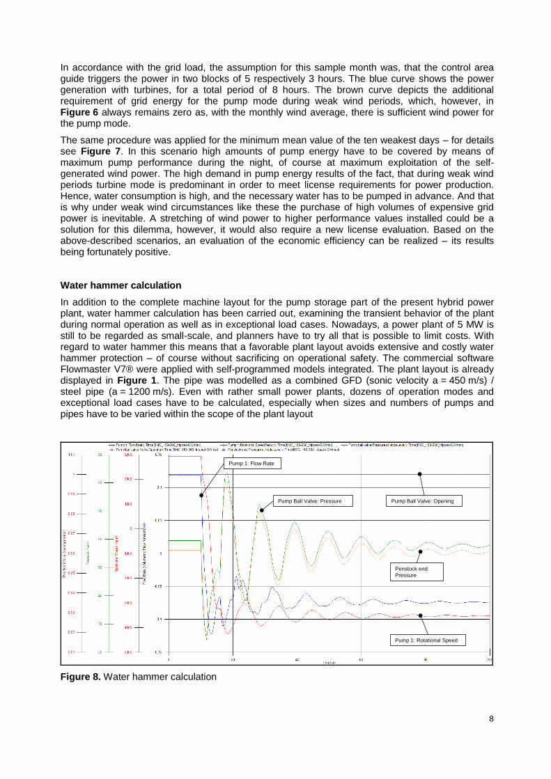
In addition to the complete machine layout for the pump storage part of the present hybrid power plant, water hammer calculation has been carried out, examining the transient behavior of the plant during normal operation as well as in exceptional load cases. Nowadays, a power plant of 5 MW is still to be regarded as small-scale, and planners have to try all that is possible to limit costs. With regard to water hammer this means that a favorable plant layout avoids extensive and costly water hammer protection – of course without sacrificing on operational safety. The commercial software Flowmaster V7® were applied with self-programmed models integrated. The plant layout is already displayed in Figure 1. The pipe was modelled as a combined GFD (sonic velocity a = 450 m/s) / steel pipe (a = 1200 m/s). Even with rather small power plants, dozens of operation modes and exceptional load cases have to be calculated, especially when sizes and numbers of pumps and pipes have to be varied within the scope of the plant layout
Pump 1: Flow Rate
Pump Ball Valve: Opening
Pump 1: Rotational Speed
Penstock end:
Pressure
Pump Ball Valve: Pressure
Figure 8. Water hammer calculation

9
Load rejection/Pump trip of the pumps at full load and blocked spherical pump valve have been identified as decisive critical load cases for maximum pressure (see Figure 8).
When it comes to cavitation, the most critical load cases are identified as pump load rejection as well as headwater and starting of turbines at the same time (Figure 9). The starting behavior of the pumps and turbines and the various combinations in hydraulic short circuits can provoke non-permitted load cases as well, however the effects are less serious. Moreover, measures against pump load rejection also provide protection against other critical load cases. The results of the load rejection are displayed in Figure 8. Load rejection in stationary operation mode is being simulated at 10 sec, causing a rapid decrease in rotary speed (red) and, after the inversion of the water flow direction – as the spherical pump valve is deemed to stay open – rotates with 4000 rpm in the opposite direction. At the same time, a negative pressure valve passes through the system, which is reflected as excess pressure valve (Figure 8) and reaches more than 80 bar. It should be mentioned, that in this load case the water head will also collapse at flow reversal and cavitate.
Figure 9. Water hammer calculation: load rejection of all pumps and starting of turbines at the same time – development of flow rates and pressures at selected points
Yet, when the turbines are started at the same time, the situation is even more critical (Figure 9). Such a scenario has to be regarded as an exceptional load case as well and therefore these load cases have to be taken into account for power plant calculations as well. Figure 9 displays a supposedly unproblematic pressure development at the spherical valve. However, the development of the pressure along the pressure pipe (Figure 10) shows that in the upper pipe section static pressures have to be expected clearly below the performance level, This, however, has to be strictly avoided as it means cavitation. Besides, it has to be mentioned that the transition to the cavitation phase has not been considered in this model and so water is always regarded as fluid.
In preventing the pump from changing into holdup mode too fast or – as in the present case – to prevent a change in the rotary direction to the opposite, the negative pressure zone can easily be avoided. By means of further investigations it could be illustrated that an additional moment of inertia of 40 kgm
2 helps to avoid the negative pressure zone. However, the excess pressure from the
reflected low pressure wave still remains, yet with a further increase of the moment of inertia to 60 kgm
2 it decreases back to a value under PN 63 and allows for the installation of GFD pipes in the
upper and of steel pipes in the lower section.

10
Figure 10. Water hammer calculation: load rejection of all pumps and starting of turbines at the same time – minimum and maximum pressure in the pressure pipe
Summary and outlook
The calculations and scenarios presented demonstrate that realization of a system without surge or air chamber is feasible. Simultaneous load rejection of all pumps proved to be the most critical load case. In order to avoid cavitation within the system, additional fly-wheel/centrifugal mass for the pumps is essential, A highest rated pressure of PN40 for the GFD pipe is sufficient, whereas PN63 is adequate for the steel pipe and the shut-off valve section. After all, the plant can be operated profitably.
References
[1] Electric energy production license, English translation of 2010-09-16.
[2] Papaefthymiou, S. et al, “Operating Policies for Hybrid Wind-Hydro Power Stations in Island Grids”, IET Renewable Power Generation, Volume 3, Issue 3, 2009, Pages 293-307.
[3] Theodoropoulos, P., Zervos, A., Betzios, G., “Hybrid Systems using Pump-storage Implementation in Ikaria Island”.
[4] Papaefthymiou, S.V. et al, “A wind-hydro-pumped storage station leading to high RES penetration in the autonomous island system of Ikaria”, IEEE Transactions on Sustainable Energy, Volume 1, Issue 3, October 2010, Article number 5512672, Pages 163-172, 2010.
[5] Castronuovo, E.D., Lopes, J.A.P., “Optimal operation and hydro storage sizing of a wind-hydro power plant”, International Journal of Electrical Power and Energy System 26 (10), pp. 771-778, 2004.
[6] Castronuovo E.D., Peças Lopes J.P., “On the Optimization of the Daily Operation of a Wind-Hydro Power Plant, IEEE Transactions on power systems, vol. 19, no. 3, August, 2004.

11
Author(s)
Helmut Benigni, Helmut Jaberg and Stefan Höller
Institute of Hydraulic Fluid Machinery, University of Technology
A-8010 Graz / Austria, Kopernikusgasse 24
Phone: +43 316 873 7578, Mail: [email protected]
Helmut Benigni, Dr. Dipl.-Ing., studied mechanical engineering at the Technical University of Graz, specialisation in numerical simulation, dissertation in optimisation of hydraulic machines. In post-doctoral position responsible for hydraulic machine simulations with the help of CFD-methods. Vice-head of the Institute of Hydraulic Fluid Machinery, Technical University of Graz.
Helmut Jaberg, Prof. Dr.-Ing., studies of aeronautical engineering in Stuttgart, Munich and Southampton, head of a pump development division and a business unit at KSB, certified expert for water hammer and unsteady behaviour of different power plants. Head of the Institute of Hydraulic Fluidmachinery, Graz University of Technology.
Stefan Höller, Dipl.-Ing., studied mechanical engineering at Graz University of Technology. Research Assistant at the Institute of Hydraulic Fluid Machinery, concentrating on numerical simulation with specialisation in hydraulic transients.