modeling of hydro-pneumatic energy storage using pump … filemodeling of hydro-pneumatic energy...
TRANSCRIPT

HAL Id: hal-00802251https://hal.archives-ouvertes.fr/hal-00802251
Submitted on 19 Mar 2013
HAL is a multi-disciplinary open accessarchive for the deposit and dissemination of sci-entific research documents, whether they are pub-lished or not. The documents may come fromteaching and research institutions in France orabroad, or from public or private research centers.
L’archive ouverte pluridisciplinaire HAL, estdestinée au dépôt et à la diffusion de documentsscientifiques de niveau recherche, publiés ou non,émanant des établissements d’enseignement et derecherche français ou étrangers, des laboratoirespublics ou privés.
MODELING OF HYDRO-PNEUMATIC ENERGYSTORAGE USING PUMP TURBINES
Egoi Ortego, Antoine Dazin, Guy Caignaert, Frédéric Colas, OlivierCoutier-Delgosha
To cite this version:Egoi Ortego, Antoine Dazin, Guy Caignaert, Frédéric Colas, Olivier Coutier-Delgosha. MODELINGOF HYDRO-PNEUMATIC ENERGY STORAGE USING PUMP TURBINES. 17th InternationalSeminar on hydropower Plants, Nov 2012, Austria. pp.117-128. �hal-00802251�

MODELING OF HYDRO-PNEUMATIC ENERGY STORAGE USING PUMP TURBINES
E. Ortego, A. Dazin, G. Caignaert, F. Colas, O. Coutier-Delgosha
Abstract: Modelling of a hydro-pneumatic energy storage system is the main aim of this paper. The project aims to model a prototype that uses a rotodynamic multi-stage pump-turbine to displace a virtual liquid piston for air compression (Figure 1). A dynamic model of the storage system is developed using the block diagram methodology. Two driving strategies are also developed in order to manage the constant variation of operating point due to pressure variation: maximum efficiency strategy and power demand response strategy.
1 Introduction
Energy storage is one of the most exciting solutions considered by electrical network managers for the current and future increasing stresses on these networks. This is the subject of many R&D projects. Actually, energy storage has different applications such as daily power picks shaving (i.e. equilibrium between day and night consumption) and can really help renewable sources integration in current electrical networks [1].
Currently, large hydraulic pumped storage is a widely used solution, but many other chemical, mechanical, thermal, pneumatic or electrical technologies are in development or in use. Different purposes call for different technologies, which can be classified in terms of delivered power and energy capacities. Hydraulic storage or compressed air energy storage (CAES) can be used in energy applications like pick shaving. Flywheels or super capacitors are more often used for power application (flicker compensation for example) [1].
Large storage capacities and high power rates are the main assets of pumped hydraulic storage that has to face its dependence on natural sites for accumulation and resulting drawbacks (environmental impact or lack of new sites in Europe). CAES can be spatially flexible but has relatively low conversion efficiency. Hydro-pneumatic energy storage (HYPES) can combine the both. It is based upon air compression storage using a hydraulic drive, which allows relatively high conversion efficiencies and power densities. The basic idea is to compress air in a closed vessel by means of a liquid piston during storage phase and use this potential energy when needed to drive a turbine (fig. 1).
Thus, HYPES was developed by different teams in Switzerland [2] and the USA [3], [4]. Structures proposed by these teams use closed or open gas cycles, i.e. single compression and storage volume (fig. 1) or separated compression and storage volumes implying compressed air displacement into separated storage vessels. Another aspect in these works is the use of a physical separation between air and the compressing liquid piston. One of the objectives for these works is to be close to an isothermal cycle in order to obtain relatively high storage efficiencies.

Figure 1: schematic description of the system & some details on the test rig
Our project aims to analyse the possibility of using a rotodynamic pump turbine to drive the liquid and estimate the advantages of a closed cycle using no separation between air and water. The test rig (fig.1) is composed by a high pressure steel vessel (40 bar), a low pressure vessel, a multistage rotodynamic reversible pump-turbine and an electric motor/generator. This project is carried out thanks to the financial support of the French agency for environment and energy management (ADEME), which actively induces research on smart grids and storage solutions.
The present paper proposes models for simulation of HYPES test rig dynamic behaviour, definition of driving strategies of the system and some simulation results.
2 Modelling
The current model, used to simulate the behaviour of the actual test rig configuration, is the first step of a smart grid configuration analysis.
The model can be divided into the different physical domains involved in the process. Analysed domains are: mechanical, hydraulic and thermal. In addition to the last one, a mass diffusion sub-model can be added. Figure 2 presents an electrical analogy for these sub-models.
The left hand side torque source (Figure 2, ) is the motor. Inductive elements ( ) represent the mechanical and hydraulic inertias. Capacitances in the thermal sub-
model represent internal energy accumulation in internal air ( ), vessel wall ( ) and
external air ( ). Resistive elements ( ) correspond to various energy losses.
Figure 2: sub-models of the physical sub-domains
Com
pre
ssed
Air
Recovery
Storage
1-Siemens bipolar 70kW electric motor
2-KSB Multitec A50/12A pump/turbine
3-Hight pressure vessel
4-Feeding vessel
1
2
3
4

The transformers are used to illustrate the relationship between the sub-models
associated to the pump/turbine’s characteristics (left) and the vessel behaviour. The
following sub-sections present some details for these elements
2.1 Vessel modelling
The model of the storage vessel takes into account the elements located at the right of the hydraulic inertial element: internal energy accumulation of the moist air, internal convective thermal resistance, vessel wall, external convective resistance and external air modelled as very high capacitance accumulator; this last element can also simply be modelled as a perfect temperature source.
2.1.1 General equations
Energy accumulation is done by the increase of the air pressure produced as the liquid piston moves. There are potentially strong interactions between air and water and compressed volume cannot be considered as dry air. This wet air is considered as a closed volume and the energy equation during an infinitesimal volume variation is written as follows:
This equation shows the variation of internal energy caused by the heat flux ( ) and
the mechanical work ( ) obtained from the pressure and the volume variation of the compression space. Here is computed being equal to water flow volume arriving to the vessel.
The internal energy variation is written for both the dry air and vapour masses inside the vessel:
The energy equation is integrated in time to obtain the temperature variation produced by the volume variation. The partial pressures of dry air and vapour are deduced from ideal gas law.
Heat flux, , can be modelled as a global exchange coefficient multiplying a temperature difference ( ) so that we can write:
Then equation 2.4 shows that for a natural polytropic transformation (air compression or expansion) where the unknown is temperature, balancing of the two first terms, i.e. heat flow and work, avoids a temperature variation. Temperature changes if one of these is higher than the other. A storage-recovery cycle example is shown in Figure 3.
This cycle is composed of a compression (Figure 3, 12’), a time delay (2’3), an expansion (34) and another time delay (41). Compression and expansion are more or less close to adiabatic or isothermal evolutions depending on the importance of K with regard to the mechanical work. During time delays, heat exchanges affect the pressure towards the isothermal pressure; the importance of the pressure variation depends directly upon the time delay duration.

Figure 3: a cycle example
Figure 4: efficiency of a cycle
Efficiency of such a storage cycle can be estimated as follows:
∫
∫
Then it is possible to make modifications of the time delay and observe the behaviour
of (see Figure 4). In figures 3 & 4, D is defined as the ratio between waiting time and the compression time. In this example, the initial pressure is 5 bar, the initial volume is 1m3 and the final volume is 0.1 m3. Continous 20 m3/h flow rate is configured alternavly positif and negatif. Therefore four situations appear in Figure 4:
K close to 0: the high efficiency zone corresponds to a purely adiabatic cycle;
whatever is the time delay, if heat can be stored, the efficiency will be 1.
D close to 0: efficiency remains high because instead of taking the path 1-2’-3-4
(Figure 3), the path is 1-2’-1 (should be 1’ bellow 1); in this case losses during time
delay are avoided.
At increasing values of D and for “low” K values efficiency decreases. This is a
classical Polytropic cycle with long time delay; this could be the more realistic since
time delay is not a controlled parameter.
For higher values of K, efficiency increases because even if heat is “given” to the
ambient (or another heat storage device) during compression, heat will be
recovered during expansion, and thus a relatively high pressure is maintained
(isothermal path).
Consequently, two possibilities appear: try to minimize K or to maximize it. The first one implies large heat storage systems and extremely effective heat insulation capacities that call for potentially expensive technology. The second solution needs great heat exchange capacities that increase with the power rate of the storage device.
Estimations done on the magniude of heat fluxes show relatibly low values for our particular case of storage vessel configuration. Increasing this fluxes needs thinking on new vessel geometries or using a heat exchangers.
0 1 2 3 4
01
00
20
03
00
40
0
D
K (
W/K
)
0.5
0.6
0.7
0.8
0.9
0.5
0.6
0.7
0.8
0.9
EFFICIENCYP
(b
ar)
2’ 3
Time...
P (
ba
r)
1
𝐷 𝑡
𝑡
𝑡 𝑡
1
2
4
3
Isothermal: K big
2’ Polytropic with long wait time
V max V min V (m3)
Adiabatic: K=0

2.2 Mechanics &Pump/turbine
2.2.1 Mechanic shaft
Pump is driven by a squirrel cage electrical motor. The shaft between the motor and the hydraulic machine is modelled as association of mechanical inertias and an angular spring.
2.2.2 Pump steady behaviour
The main originality of this project lies in the use of a rotodynamic pump-turbine. This is a commercial one, whose characteristics are given by the manufacturer. Characteristics for the whole operating range are obtained with the use of dimensionless parameters, assuming negligible Reynolds effects:
Figure 5: pump characteristics
Figure 6: turbine characteristics
Figures 8 & 9 present the dependence of operating point on conversion efficiency i.e. pressure, water flow rate and angular speed. Since the pump/turbine is a multistage radial flow one, the pressure coefficient is quite high whereas the flow coefficient is relatively low. These are the steady operating characteristics, and one of the objectives of experimental phase is the validation of these curves for dynamic operating conditions and the necessity or not of a full dynamic model of the device [10].
2.2.3 Angular velocity command of the pump-turbine
Energy accumulation by air compression is not a natural application for rotodynamic pumps. The main difference with its usual applications is the constant and potentially rapid variation of the operating conditions. The natural answer to this point lies in the use of a pressure dependent angular speed in order to maintain its best efficiency point (BEP). This becomes a problem when trying to store or recover a given power rate function of the network manager requirements (see Figure 7&Figure 8).
Figure 7 and Figure 8 illustrate how, in the best efficiency operating conditions, the power of the machine is related to the pressure (dotted line in Figure 7 & Figure 8); variation of it avoids maintaining the efficiency at the same power rate. Some details on efficiency or power maintaining are given in the following sub-sections.

2.2.3.1 Maintaining efficiency
The efficiency of the pump-turbine depends on the angular speed for a given pressure. The characteristic curves are used to drive the pump-turbine’s angular speed as a function of pressure in order to keep the BEP .
(
)
This method requires a good knowledge of the machine and is based upon the hypothesis that, during transient operating conditions, pump’s behaviour is identical to the steady one and, this, for the whole pressure range.
Another possibility relies on the use of an algorithm that “checks” the efficiency at a given frequency. This algorithm can use the “perturb-observe” principle well known for example in photovoltaic domain. The basic idea is to measure the efficiency variation produced by a speed perturbation applied to the machine. This is illustrated by Figure 9:
Figure 9: perturb-observe principle applied to BEP maintaining
Using this method, efficiency depends upon the frequency of this operation and on uncertainties and dynamic response of the sensors necessary to estimate efficiency.
2.2.3.2 Power requirement constraint
In most energy storage applications, power is the main parameter to be controlled. In order to produce the required power for a given pressure the machine’s characteristics are used in the form of “look-up” table that give angular speed information for a couple of power/pressure entries.
A “perturb-observe” algorithm can also drive angular speed. In this case, the gap between a reference and an effective power has to be minimized instead of maximizing the efficiency.
Qv (m3/h) Pu = cst
𝜼 ↓
Pu ↑
ω = cst
Pump behaviour P
(b
ar)
Pu ↓
𝜼 ↓
𝜼𝒎𝒂𝒙
𝜼𝒎𝒂𝒙 𝒄𝒔𝒕 Pu = cst
𝜼𝒎𝒂𝒙
Pu ↑
ω = cst Turbine behaviour
Pu ↓
𝜼 ↓
𝜼 ↓
Qv (m3/h)
P (
ba
r)
Figure 7: pump behaviour Figure 8: turbine behaviour

As already noticed efficiency and power can’t be simultaneously maintained. A solution can be the use of several vessels in parallel, pre-charged at different pressures in order to choose the better-adapted vessel for the required power. Simulations done with such a configuration are presented in § 3.2.
3 Simulation results
Simulations have been done using functional modelling in Matlab/Simulink environment. Two simulation results are presented here: First a single vessel storage/recovery cycle and then a multi-vessel configuration.
3.1 Storage cycle simulation
A first example of what a storage cycle looks like is presented. Operating conditions of the compression-expansion cycle are a 5 bar initial pressure, 40 bar final pressure, a BEP driving strategy, expansion starts as soon as air reaches ambient temperature and stops when initial air volume is reached.
The evolution of various parameters is shown in Figure 10 to 17. During compression phase (0 to 150s), angular speed (Figure 10) increases in order to maintain pump-turbine’s efficiency (Figure 14). Thus the flow rate (Figure 11) increases when pressure grows (Figure 12). This produces an increase of air temperature in the vessel (Figure 13). Then, during the wait period (150 to 300s) temperature, thus pressure, decreases because of heat losses. Finally, during expansion, angular speed decreases, as a consequence of pressure’s evolution.
Figure 10: angular speed
Figure 11: flow rate
Figure 12: pressure
Figure 13: air mean temperature
Figure 14:machine efficiency
Figure 15: PV diagram
Figure 15 proposes a comparison between the calculated pressure and the isothermal and isentropic ones in function of air volume; the pressure evolves inside the space limited by the two others. Various efficiencies have been calculated:
- Storage efficiency (pneumatic energy input/output factor) is about 61%
- Pump-turbine global efficiency 53% (i.e. 68% during compression phase, 78% during expansion)
- Overall efficiency for that cycle is 33%.
This efficiency is obviously not very high. Ways to improve it could be:
- Using separated machines in order to increase individual operating efficiencies.
- Increasing heat transfer coefficient to increase storage efficiency.
0 100 200 300 400 500-200
-100
0
100
200
300
Time (s)
Angula
r speed (
rad/s
)
0 100 200 300 400 500
-40
-20
0
20
40
Time (s)
Flo
w r
ate
(m
3/h
)
0 100 200 300 400 5000
1
2
3
4x 10
6
Time (s)
Pre
ssu
re (
ba
r__a
bs)
0 100 200 300 400 500
200
250
300
350
400
Time (s)
Air t
em
pe
ratu
re (
K)
0 100 200 300 400 500
0
0.2
0.4
0.6
0.8
1
Time (s)
Hydra
ulic
convers
ion
eff
icie
ncy
3.2 Multi-vessel
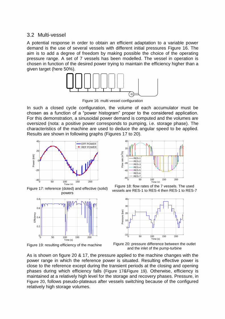
A potential response in order to obtain an efficient adaptation to a variable power demand is the use of several vessels with different initial pressures Figure 16. The aim is to add a degree of freedom by making possible the choice of the operating pressure range. A set of 7 vessels has been modelled. The vessel in operation is chosen in function of the desired power trying to maintain the efficiency higher than a given target (here 50%).
Figure 16: multi vessel configuration
In such a closed cycle configuration, the volume of each accumulator must be chosen as a function of a “power histogram” proper to the considered application. For this demonstration, a sinusoidal power demand is computed and the volumes are oversized (nota: a positive power corresponds to pumping, i.e. storage phase). The characteristics of the machine are used to deduce the angular speed to be applied. Results are shown in following graphs (Figures 17 to 20).
Figure 17: reference (doted) and effective (solid)
powers
Figure 18: flow rates of the 7 vessels. The used
vessels are RES-1 to RES-4 then RES-1 to RES-7
Figure 19: resulting efficiency of the machine
Figure 20: pressure difference between the outlet
and the inlet of the pump-turbine
As is shown on figure 20 & 17, the pressure applied to the machine changes with the power range in which the reference power is situated. Resulting effective power is close to the reference except during the transient periods at the closing and opening phases during which efficiency falls (Figure 17&Figure 19). Otherwise, efficiency is maintained at a relatively high level for the storage and recovery phases. Pressure, in Figure 20, follows pseudo-plateaus after vessels switching because of the configured relatively high storage volumes.
0 50 100 150 200-40
-20
0
20
40
Time (s)
Pow
er
(kW
)
EFF POWER
REF POWER
0 50 100 150 200-60
-40
-20
0
20
40
Time (s)
Flo
w r
ate
(m
3/h
)
RES-1
RES-2
RES-3
RES-4
RES-5
RES-6
RES-7
0 50 100 150 2000
0.2
0.4
0.6
0.8
Time (s)
Effic
iency
0 50 100 150 200-10
0
10
20
30
40
Time (s)
Pre
ssure
(bar)

4 Conclusion
Hydro-pneumatic storage systems solutions can be completed by the concept proposed here using a rotodynamic pump turbine and a free surface configuration. Since experimental results are not yet available, only simulation approach has been developed in the present paper. The model introduces, as it is currently possible, the dynamic modelling of this system.
The key issues of such a HyPES system have been illustrated: storage efficiency and power control. The increase of the efficiency should certainly need the increase of heat transfer coefficient. A power variable situation has been implemented and simulated. Other power management solutions will be evaluated such as the use of a secondary power flexible storage system [2] or pump and turbine simultaneous operation for power compensation (hydraulic short circuit) [11].
The model must be completed/corrected in a very next future by experimental observations that will help for the validation of more realistic values for the considered physical parameters. After the validation, economic considerations will be added in order to propose potential fields of application of such a storage method.
5 Nomenclature
Specific heat at constant volume of gas Specific gas constant
Wait/compression times ratio Space averaged temperature
Considered torque Internal energy
Considered convectif heat transfer coefficient Gas volume
Considered inertia Global heat flow
Global heat transfer coefficient u p turbine’ pre ure
Mass of considered element Mass density
Total storage gas pressure Dimensionless flow
Partial pressure of considered element Considered efficiency
Considered heat flow Dimensionless power
Flow rate Dimensionless pressure
Pump/turbine wheel radius Pump/turbine angular velocity
Considered resistance
References
[1] : Gauthier Marc Aime DELILLE. Contribution du Stockage à la Gestion Avancée des Systèmes Electriques, Approches Organisationnelles et Technico-économiques dans les Réseaux de Distribution. PhD. Thesis. Ecole Centrale de Lille. 2010. [2]: Sylvain LEMOFOUET – GATSI. Investigation and optimisation of hybrid electricity storage systems based on compressed air and supercapacitors. Ph.D thesis at Ecole Polytechnique Fédérale de Lausanne. 2006. [3]: T. McBride et al. “Systems and method for energy storage and recovery using rapid isothermal gas expansion and compression”. USA Brevet US7874155, 25 01 2011. [4]: K. Stahlkopf et al. “Compressed Air Energy Storage System Utilizing Two-Phase Flow to Facilitate Heat Exchange”. USA Brevet US2011/0115223, 19 05 2011. [5]: T. Taine, J. P. Petit. Transferts thermique-Mécanique des fluides anisothermes. Dunod. 1998.

[6]: R. Giblin. Transmission de chaleur par convection naturelle. Collections de l’A.N.R.T. 1974. [7]: A. Pourmovahed, D.R. Otis. An experimental Thermal Time Constant Correlation for Hydraulic Accumulators. Journal of Dynamic Systems, Measurement and Control - March 1990 - Vol. 110. [8]: F. P. Incropera, D. P. DeWitt. Fundamentals of Heat and Mass Transfer. John Wiley & Sons. 2002. [9]: A. H. Harvey, S. G. Kaplan, and J. H. Burnett (2005) - Effect of Dissolved Air on the Density and Refractive Index of Water - International Journal of Thermophysics, Vol. 26, No. 5, Sept 2005. [10]: A. Dazin, G. Caignaert, G. Bois. Transient Behavior of Turbomachineries: Applications to Radial Flow Pump Startups. ASME, Journal of Fluid Eng., Vol 129. 2007. [11]: «http://www.kopswerk2.at/downloads/Folder_061006_englisch.pdf»
Authors
Egoï Ortego. PhD student.
Arts et Métiers ParisTech Lille
Mechanics Laboratory (LML)
8, bd. Louis XIV, 59046 Lille, FRANCE
E-mail : [email protected]
Egoï Ortego is a former student of Arts et Métiers ParisTech. After a specialization on renewable energy sources he prepares a PhD on the study of a hydro-pneumatic energy storage system.
Dr. Antoine Dazin
Arts et Métiers ParisTech Lille
Mechanics Laboratory (LML)
8, bd. Louis XIV, 59046 Lille, FRANCE
E-mail : [email protected]
Dr Dazin is associated professor at Arts et Metiers ParisTech since 2006. He is a researcher at LML. His interest is in turbomachinery (model of turbomachinery behavior during fast transient periods, analysis of the internal flow at off design operating point and use of optical measurement techniques). He obtained his PhD from Lille University in 2003.
Prof. Guy Caignaert
Arts et Métiers ParisTech Lille
Mechanics Laboratory (LML)
8, bd. Louis XIV, 59046 Lille, FRANCE
E-mail : [email protected]
Professor Caignaert has been professor at Arts et Métiers Paris Tech since 1989. His main research activities are related to internal fluid mechanics within turbomachines. The main topics are: off-design behaviour of pumps, instabilities in radial flow turbomachines, hydro acoustics in pump systems, cavitation of pumps, experimental methods.
Dr. Frédéric Colas
Arts et Métiers ParisTech Lille
Laboratory of Electrical Engineering and Power Electronics (L2EP)
8, bd. Louis XIV, 59046 Lille, FRANCE
E-mail : [email protected]
Frédéric Colas obtained his PhD from L2EP & LAGIS working on dynamic behavior and control of cartesian robots for SEPRO-Robotics in 2006. Since 2009, he works as research engineer at L2EP on the integration of renewable energy sources in the electrical network
Dr. Olivier Coutier-Delgosha
Arts et Métiers ParisTech Lille
Mechanics Laboratory (LML)
8, bd. Louis XIV, 59046 Lille, FRANCE
E-mail: [email protected]
Dr. Coutier-Delgosha obtained his PhD from INPG (Grenoble, France) in 2001 and became associate professor in Arts et Métiers ParisTech in 2004. He conducts a research in the fields of cavitating flows and turbomachinery, based on joint experimental and numerical works