hy3500p - princess auto
TRANSCRIPT

HY3500P
User Manual

This product can expose you to chemicals including carbon monoxide, which is known to the State of California to cause cancer and birth
defects or other reproductive harm. For more information go towww.P65Warnings.ca.gov
©2020 Hyundai Power Equipment. All Rights Reserved.Licensed by Hyundai Corporation, Korea.
HY3500P_UG_EN_2019-12-20

Thanks for choosing the HY Series!You're excited to power up, so we'll keep this brief. Let's get started!
THIS PRODUCT MEETS ALL CERTIFICATION REQUIREMENTS FROM:

WE'VE GOT YOU COVERED!Contact us by phone at 1-877-528-3772,
email us at [email protected], or visit us online at www.hyundaipower.ca if you have any questions
SAVE THESE INSTRUCTIONS
This user guide contains important instructions for your product, that should be followed during installation and
maintenance of the generator.
This user guide covers the safety, operation and maintenance procedures for the HY3500P.
All information in this publication is based on the latest product information available at the time of print.
Visit www.hyundaipower.ca for user guideupdates and operation notices.
No part of this publication may be reproducedwithout written permission.

WARRANTY INFORMATION
YOU CAN REGISTER EASILY USING OUR ONLINE FORM:
www.hyundaipower.ca/register-warrantySee ‘Limited Warranty’ for more information.
Product registration will allow you to request warranty support in
the future. Product registration is required for all product support
and warranty coverage.
Warranty support, operation assistance and product support
is provided by Midland Power Inc., a licensed manufacturer of
Hyundai Power Equipment. Please contact us directly for any
warranty service questions.
www.hyundaipower.ca

HY SERIES
TABLE OF CONTENTS
1. Safety 1
2. Learn About Your Generator 5
2.1 Component Identification 5
2.2 Control Panel 6
2.3 Control Functions 7
2.4 Make Sure You Have Everything 9
3. Pre-Operation Check 10
3.1 Check the Oil Level 10
3.2 Check the Fuel Level 12
3.3 Connect the Battery 13
3.4 Prepare the Air Cleaner 14
4. Starting the Engine 15
4.1 Starting Your Generator 16
5. Generator Use 19
5.1 Output, Overload, and Oil Alert Indicator 19
5.2 DC Applications 20
5.4 AC Parallel Operation 21
5.3 AC Applications 22
6. Stopping the Engine 23
7. Maintenance 24
7.1 Maintenance Schedule 25
7.2 Changing the Oil 26
7.3 Cleaning the Air Filter 28
7.4 Spark Plug Service 29
7.5 Spark Arrester Maintenance 30
7.6 Replacing the Battery 31
7.7 Fuel Filter Maintenance 32
7.8 Emission Control System 33
8. Transportation & Storage 35
9. Troubleshooting 37
10. Technical Specifications 39
11. Wiring Diagram 39
12. Appendix 40
13. Limited Warranty 42

1
1. SAFETY
DANGER!
Using a generator indoors can kill you in minutes.
Generator exhaust contains carbon monoxide. This is a poison that you cannot see or smell.
NEVER use inside a home or garage.
WARNING!
This product can expose you to chemicals including carbon monoxide, which is known to the State of California to cause cancer and birth defects or other reproductive harm. For more information go to www.P65Warnings.ca.gov
1.1 OPERATOR SAFETY
WARNING!
Always perform an oil, fuel and air filter check before starting the engine.
Properly clean and maintain the equipment.
Operate the generator according to instructions for safe and dependable service.
Before operating the generator, read the user guide carefully. Otherwise, personal injuries or equipment damage may result.
Never run the generator in an enclosed area to avoid harm from exhaust emissions of a poisonous carbon monoxide gas.
Pay attention to the warning labels. The engine exhaust system will become heated during operation and remain hot immediately after the engine is stopped.
Avoid other generator hazardsREAD MANUAL BEFORE USE.
Using a generator indoors can KILL YOU IN MINUTES. Generator exhaust contains carbon monoxide. This is poison that you cannot see or smell.
NEVER use inside a home or garage. EVEN if doors and windows are open.
Only use OUTSIDE and far away from windows, doors, and vents.
TOXIC FUMES HAZARD. Running engines give off carbon monoxide, an odourless poisonous gas that can cause nausea, fainting, or death. Do not start engine indoors or in an enclosed area, even if the windows and doors are open.
DANGER TOXIQUE. Faire fonctionner un moteur dégage de l’oxyde de carbone, un gaz inodore toxique qui peut provoquer la nausée, évanouissement ou la mort. Ne démarrer pas le moteur à l’intérieur ou dans une espace clos, meme si les fenêtres et les portes sont ouvertes.

2
Gasoline is a highly flammable and explosive liquid. Refuel in a well ventilated area with the engine stopped.
Use of gasoline with an ethanol content greater than 10% can damage the engine and fuel system and will void the manufacturer’s warranty.
When refueling the generator, keep it away from cigarettes, open flames, smoke and/or sparks.
Place the generator at least 3 feet away from buildings or other equipment during operation.
Run the generator on a level surface. Tilting the generator may result in fuel spills.
Do not touch the spark plug while the engine is operating or shortly after the engine has been shut down.
Know how to stop the generator quickly and understand operation of all the controls. Never permit anyone to operate the generator without proper instructions.
Keep children, pets and machinery with rotating parts away during operation.
Do not operate the generator in rain or snow.
Do not allow any moisture to come in contact with the generator.
1.2 AC SAFETY
WARNING!
Before connecting the generator to an electrical device or power cord:
Make sure that everything is in proper working order. Faulty devices or power cords can lead to an electrical shock.
Turn off the generator immediately if the device begins to operate abnormally. Then disconnect the device and investigate the problem.
To prolong engine life, do not exceed the rated running wattage.
Keep away from other electric cables or wires.
Make sure that the electrical rating of the device does not exceed that of the generator. If the power level of the device is between the maximum output power and the running power of the generator, the generator should not be used for more than 30 minutes.
When an extension cable is required, be sure to use a tough rubber sheathed flexible cable (according to IEC245 or equivalent standards). The maximum length of the extension cable: 196 feet (60 meters) for cable of 15.5 gauge (1.5mm2); 328 feet (100 meters) for cable of 13.25 gauge (2.5mm2).
HY SERIES

3
Connections for standby power to a building’s electrical system must be done by a qualified electrician and must comply with all applicable laws and electrical codes. Improper connections may cause serious injuries to electrical workers during a power outage, and when the utility power is restored, the generator may explode or cause fires. The generator shall be connected through transfer equipment that switches all conductors other than the equipment grounding conductor. The frame of the generator shall be connected to an approved grounding electrode.
For power outages, permanently installed stationary generators are better suited for providing backup power to the home. Even a properly connected portable generator can become overloaded. This may result in overheating or stressing the generator components, possibly leading to a generator failure.
This unit is floating neutral. The generator (stator winding) is isolated from the frame and from the AC receptacle ground pin.
Electrical devices that require a grounded receptacle pin connection will not function if the receptacle ground pin is not functional.
1.3 MAINTENANCE SAFETY
WARNING!
After any maintenance is performed, wash immediately using soap and clean water because repeated exposure to lubricant may cause skin irritation.
Do not clean the filter element with flammable liquids like gasoline because an explosion may occur.
Allow the generator set to cool down and turn off the engine before performing any maintenance. Failure to do so can cause severe personal injury or death.
Always wear safety glasses when cleaning the generator set with air.
Do not clean the generator set with a pressure washer because it can damage the generator set.
When working with batteries, ventilate the area, use safety glasses, do not smoke. Always disconnect the negative first and reconnect it last.
Use rubber gloves when coming into contact with engine oil.
Always stop the generator set before removing the oil filler cap.
Only qualified maintenance personnel with knowledge of fuels, electricity, and machinery hazards should perform maintenance
procedures.

4
1.5 OTHER SAFETY TIPS
WARNING!
To avoid breathing in poisonous carbon monoxide from the exhaust gases, adequate ventilation should be provided if the generator set is running in a partially enclosed space.
If the generator set is stored outdoors, check all the electrical components on the control panel before each use. Moisture can damage the generator and can lead to an electric shock.
Do not connect an extension to the exhaust pipe.
Generators vibrate in normal use. During and after the use of the generator, inspect the generator as well as extension cords and power supply cords connected to it for damage resulting from vibration. Have damaged items repaired or replaced as necessary. Do not use plugs or cords that show signs of damage such as broken or cracked insulation or damaged blades.
If you start to feel sick, dizzy, or weak after the generator has been running, move to fresh air RIGHT AWAY. See a doctor. You could have carbon monoxide poisoning.
Avoid other generator hazardsREAD MANUAL BEFORE USE.
Using a generator indoors can KILL YOU IN MINUTES. Generator exhaust contains carbon monoxide. This is poison that you cannot see or smell.
NEVER use inside a home or garage. EVEN if doors and windows are open.
Only use OUTSIDE and far away from windows, doors, and vents.
TOXIC FUMES HAZARD. Running engines give off carbon monoxide, an odourless poisonous gas that can cause nausea, fainting, or death. Do not start engine indoors or in an enclosed area, even if the windows and doors are open.
DANGER TOXIQUE. Faire fonctionner un moteur dégage de l’oxyde de carbone, un gaz inodore toxique qui peut provoquer la nausée, évanouissement ou la mort. Ne démarrer pas le moteur à l’intérieur ou dans une espace clos, meme si les fenêtres et les portes sont ouvertes.
HY SERIES
1.4 RUNNING GENERATORS IN PARALLEL
WARNING!
Only connect in parallel with an approved Hyundai parallel kit to another Hyundai model featuring parallel. Attempting to connect other brands or models will void your warranty and could cause bodily injury.
5
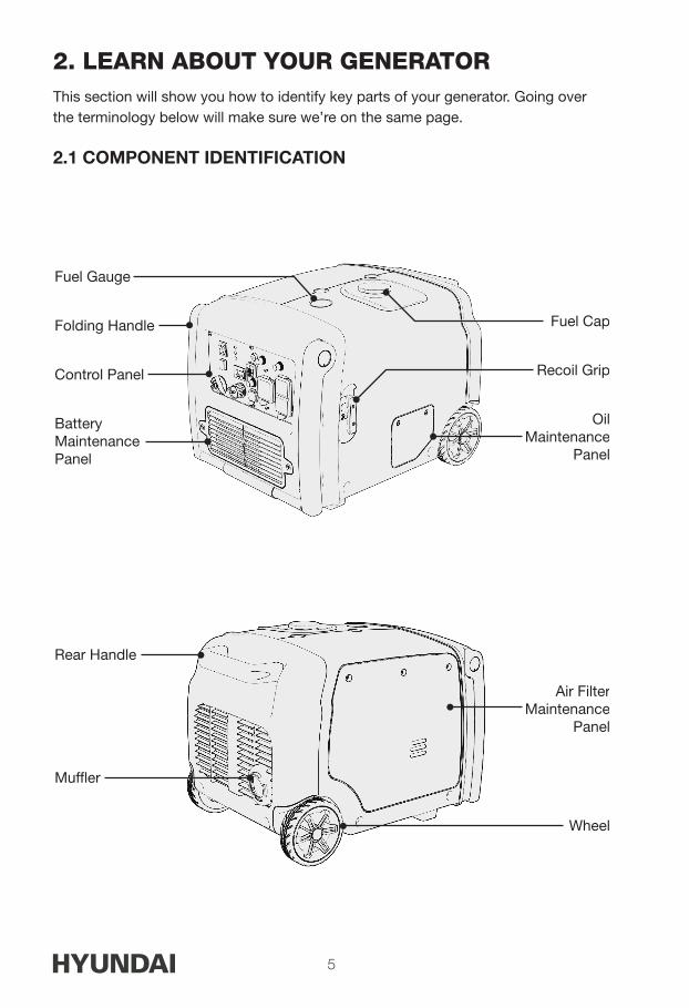
2. LEARN ABOUT YOUR GENERATORThis section will show you how to identify key parts of your generator. Going over the terminology below will make sure we’re on the same page.
2.1 COMPONENT IDENTIFICATION
Folding Handle
Control Panel
Fuel Gauge
Battery Maintenance Panel
Wheel
Air FilterMaintenance
Panel
Recoil Grip
OilMaintenance
Panel
Fuel Cap
Rear Handle
Muf�er

6
2.2 CONTROL PANEL
1. Power Button
2. EcoMode Switch
3. Fuel Shutoff
4. Indicator Lights
5. Hour Meter
6. DC Breaker
7. 12V 5A DC Receptacle
8. Reset
9. USB
10. Parallel Port
11. AC Breaker
12. 120V 25.8A (L5-30) Receptacle
13. AC Breaker
14. 120V 20A (5-20) Receptacle
15. Ground Terminal
6 7
81
2
3
4
5
9
10
11
12
13
14
15
HY SERIES

7
2.3 CONTROL FUNCTIONS
AC Circuit Breakers While the generator is running, the breakers should be put in the ON
position.
If the current has exceeded its limits it will automatically pop out to the OFF position. Reduce the electrical load on the generator and push the button back to the ON position.
DC Circuit Breakers The DC circuit breaker automatically shuts off when the charging circuit
is overloaded.
If the current has exceeded its limits the breaker will automatically pop out to the OFF position. Reduce the electrical load on the generator and push the button back to the ON position.
Display Button Press the DISPLAY button once to turn on the backlight. The hourmeter
will be shown, and the backlight will turn off after 10 seconds. Press the DISPLAY button multiple times to cycle through different information displays. The display is only powered while the unit is running.
EcoMode (Economy Control Switch) Turning EcoMode to ON is recommended for minimizing fuel
consumption. In this mode the engine will dynamically meet the demand of the current electrical load and will automatically go into an idle state if all electrical loads are disconnected.
Before connecting or removing a high load device to the generator, turn EcoMode to OFF until that device has reached running power.
When EcoMode is OFF, the engine runs at full speed.

8
Ground Terminal
WARNING!
Before using the ground terminal consult a qualified electrician, electrical inspector, or local agency having jurisdiction for local laws and codes that apply to the intended use of the generator.
The ground terminal is connected to the non-current carrying metal parts (such as the fuel tank), the frame, and the ground terminals of the AC outlets.
Low Oil Indicator Light The oil alert system is designed to prevent engine damage caused by
an insufficient amount of oil in the crankcase. Before the oil level in the crankcase reaches an unsafe limit, the oil alert system will automatically shut down the engine (the power switch remains in the ON position).
If the oil alert system shuts down the engine, the low oil indicator light (red) will turn on. Check the engine oil level.
Output and Overload Indicator In normal operation, the green output indicator light (READY TO USE)
will remain on.
If the generator is overloaded (producing more than running wattage) or a connected appliance has short-circuited, the output indicator light will turn off and the overload indicator light will turn on.
Power Switch The three-way power switch starts and stops the unit.
START: Starts the engine using the electric start system. ON: Switch must be in this position to recoil or remote start. STOP: Stops the engine.
Reset Button Use the RESET button in the case of a sudden engine overload.
Disconnect all electrical appliances and then press and hold the reset button for 1 second, this will reset the engine. After resetting, if the overload indicator light has turned off and the output indicator light has turned back on, reconnect the electrical appliances. Otherwise, stop the engine by turning the power switch to STOP, and check the generator.
NOTE
The RESET button is available a maximum of 5 times for every full start
HY SERIES

9
of the generator. Shut down the generator and restart using the power switch to refresh available resets.
If the generator is running normally, the RESET button will have no effect.
USB Ports (If Equipped) A total of 3.1A is available at 5.0V. A single port can draw the full 3.1A or
it will be distributed as needed. For example, a 1A device will only draw 1A.
2.4 MAKE SURE YOU HAVE EVERYTHING
Make sure your generator has everything listed in the table below.
Part Name Quantity Inverter Generator 1
User Guide 1
Spark Plug Wrench - Sleeve 1
Spark Plug Wrench - Bar 1
Multi Screwdriver 1
DC Charging Cable 1
Oil Transfer Tool 1
10
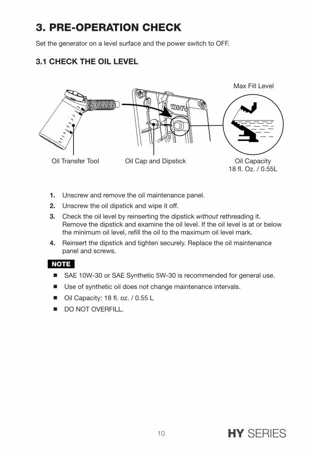
3. PRE-OPERATION CHECKSet the generator on a level surface and the power switch to OFF.
3.1 CHECK THE OIL LEVEL
1. Unscrew and remove the oil maintenance panel.
2. Unscrew the oil dipstick and wipe it off.
3. Check the oil level by reinserting the dipstick without rethreading it. Remove the dipstick and examine the oil level. If the oil level is at or below the minimum oil level, refill the oil to the maximum oil level mark.
4. Reinsert the dipstick and tighten securely. Replace the oil maintenance panel and screws.
NOTE
SAE 10W-30 or SAE Synthetic 5W-30 is recommended for general use.
Use of synthetic oil does not change maintenance intervals.
Oil Capacity: 18 fl. oz. / 0.55 L
DO NOT OVERFILL.
Oil Cap and Dipstick Oil Capacity18 �. Oz. / 0.55L
Max Fill Level
Oil Transfer Tool
HY SERIES

11
NOTE
Do not tilt the generator when adding engine oil. This could result in overfilling and damage to the engine.
Use high quality 4-stroke engine oil, certified to meet or exceed API standard SG, SF, SAE ratings with strong detergents. Using non-detergent or 2-stroke oil could shorten the engine’s working life.
Do not mix different engine oils.
Handle and store the engine oil with care, avoid getting dirt or dust into the engine oil.
Before the engine oil falls below the safety margin, the low oil alert system will automatically shut off the engine. The low oil light will turn on.
To avoid the inconvenience of unexpected engine shutoff, check the oil level as often as possible.
0°C 10 20 30 40 50-10-20-30
20 32°F 40 60 80 100 120
°C
°F0-20
15W-50
10W-30
Synthetic 5W-30
5W-30
Effective Viscosity Range of Engine Oils
12
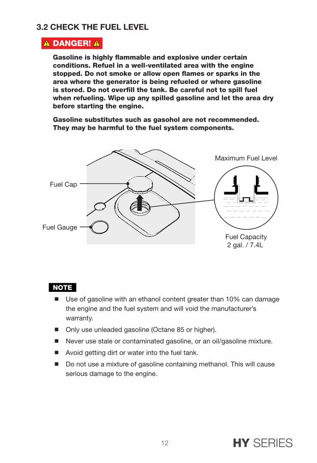
3.2 CHECK THE FUEL LEVEL
DANGER!
Gasoline is highly flammable and explosive under certain conditions. Refuel in a well-ventilated area with the engine stopped. Do not smoke or allow open flames or sparks in the area where the generator is being refueled or where gasoline is stored. Do not overfill the tank. Be careful not to spill fuel when refueling. Wipe up any spilled gasoline and let the area dry before starting the engine.
Gasoline substitutes such as gasohol are not recommended. They may be harmful to the fuel system components.
NOTE
Use of gasoline with an ethanol content greater than 10% can damage the engine and the fuel system and will void the manufacturer’s warranty.
Only use unleaded gasoline (Octane 85 or higher).
Never use stale or contaminated gasoline, or an oil/gasoline mixture.
Avoid getting dirt or water into the fuel tank.
Do not use a mixture of gasoline containing methanol. This will cause serious damage to the engine.
Fuel Cap
Fuel GaugeFuel Capacity2 gal. / 7.4L
Maximum Fuel Level
HY SERIES

13
3.3 CONNECT THE BATTERY
WARNING!
Batteries produce explosive gases. Keep sparks, flames and cigarettes away from the battery at all times. To prevent the possibility of creating a spark while using the battery, connect charging cables to battery terminals first, then to the generator. When disconnecting, disconnect the cables at the generator first.
Do not reverse the polarity of the terminals when charging the battery. Serious damage to the generator and/or battery may occur. Do not attempt to connect the battery while the generator engine is running. Disconnect the cables from the battery while the generator is in storage.
1. Loosen the two screws of the battery maintenance cover and remove it.
2. Locate the white connectors and firmly plug them in to connect the battery.
NOTE
Be sure to turn the fuel knob to the OFF position when not in use. This will disconnect the battery circuit and prevent it from draining.
3.
NOTE
Be sure to connect the battery to the generator set before operation. Failure to do so will cause the output display to function improperly.
Fuel Cap
Fuel GaugeFuel Capacity2 gal. / 7.4L
Maximum Fuel Level

14
3.4 PREPARE THE AIR CLEANER
Clean and oil the air filter before your first use. Check the maintenance section for a complete cleaning guide.
1. Unscrew and remove the air filter maintenance panel.
2. Unscrew the air filter cover and remove the filter.
3. Clean the air filter with soap and water or solvent and squeeze dry (do not wring out).
4. Soak in clean engine oil.
5. Squeeze (do not wring) out all excess oil and reinstall. Replace the filter if it is damaged.
NOTE
Running the engine without the air filter will quickly degrade the engine
Cover Screws
Air FilterMaintenance Panel
Air Filter
Air Filter Cover
HY SERIES

15
4. STARTING THE ENGINE
DANGER!
Using a generator indoors WILL KILL YOU IN MINUTES.
Generator exhaust contains high levels of carbon monoxide (CO), a poisonous gas you cannot see or smell. If you can smell the generator exhaust you are breathing CO. Even if you cannot smell the exhaust, you could be breathing CO.
NEVER use a generator inside a home, garage, crawlspace, or other partly enclosed area, deadly levels of carbon monoxide can build up in these areas. Using a fan or opening windows and doors will NOT supply enough fresh air.
ONLY use a generator outdoors and far away from open windows, doors, and vents. These openings can pull in generator exhaust. Even when you use a generator correctly, CO may leak into the home. ALWAYS use a CO alarm in your home.
If you start to feel sick, dizzy, or weak after the generator has been running, move to fresh air RIGHT AWAY and seek medical attention. You could have carbon monoxide poisoning. Never run the generator in an enclosed or even partially enclosed area where people may be present.
Avoid other generator hazardsREAD MANUAL BEFORE USE.
Using a generator indoors can KILL YOU IN MINUTES. Generator exhaust contains carbon monoxide. This is poison that you cannot see or smell.
NEVER use inside a home or garage. EVEN if doors and windows are open.
Only use OUTSIDE and far away from windows, doors, and vents.
TOXIC FUMES HAZARD. Running engines give off carbon monoxide, an odourless poisonous gas that can cause nausea, fainting, or death. Do not start engine indoors or in an enclosed area, even if the windows and doors are open.
DANGER TOXIQUE. Faire fonctionner un moteur dégage de l’oxyde de carbone, un gaz inodore toxique qui peut provoquer la nausée, évanouissement ou la mort. Ne démarrer pas le moteur à l’intérieur ou dans une espace clos, meme si les fenêtres et les portes sont ouvertes.

16
4.1 STARTING YOUR GENERATOR
NOTE
Ensure all connected appliances are turned off.
Return the starter grip slowly by hand, do not let it snap back.
If there is no battery in the generator or the battery has died, the generator can only be started using the recoil method. If there is a battery and it is drained, running the generator will recharge the battery.
A) Remote Start
1. Open the fuel valve by turning the fuel knob to the OPEN position.
2. Turn the power switch to the ON position.
3. With the power switch in the ON position, press the ON button of the remote control once to start the engine.
NOTE
When the power switch is turned to ON, the unit will enter a remote standby mode which will deactivate after 48 hours. To re-activate standby mode, turn the power switch to STOP, and then back to ON.
NOTE
The life expectancy for the remote control battery is two years. When the battery dies, unscrew the back of the remote to replace it.
Generators equipped with remote start come with two remotes. Do not lose the remotes, they are paired uniquely to the controller in your unit.
OPEN
ON
ON
1 2 3
OPEN
START
1 2
OPEN1 2 3
3
STOP
CLOSED
1 2
HY SERIES

17
B) Electric Start
1. Open the fuel valve by turning the fuel knob to the OPEN position.
2. Press and hold the power switch in the START position for 2 seconds or until engine starts then release.
C) Manual Recoil Start
1. Open the fuel valve by turning the fuel knob to the OPEN position.
2. Turn the power switch to the ON position.
3. Pull the starting grip slowly until it is engaged, then pull it quickly. Repeat until the engine starts.
4. Return the starter grip slowly by hand, do not let it snap back quickly.
OPEN
ON
ON
1 2 3
OPEN
START
1 2
OPEN1 2 3
3
STOP
CLOSED
1 2
OPEN
ON
ON
1 2 3
OPEN
START
1 2
OPEN1 2 3
3
STOP
CLOSED
1 2
18
Carburetor Modification for High Altitude Operation
At high altitudes, the standard carburetor air-fuel mixture will be too rich. Fuel consumption will increase and performance will decrease. A very rich mixture will also foul the spark plug and cause hard starting.
If using the generator at high altitudes, change the main-nozzle or adjust the idling-screw of the carburetor. If always operating the generator at altitudes above 3280 feet (1,000m), contact an authorized service center to have the carburetor modified.
Two jets are available for high altitude operation: altitudes of 5,000 to 6,500 feet (1500 - 2000m) and altitudes of 6,500 to 8,200 feet (2000-2500m)
Conversely, if the carburetor has been modified for high altitude operation, the air-fuel mixture will be too lean for low altitude use. Operation at low altitude may cause the engine to overheat and result in serious engine damage. In this case the carburetor needs to be returned to its original specifications.
Generator output power should be modified according to the altitude and ambient temperature. See more details on the correction factors in Chapter 12 - Appendix.
HY SERIES
19
5. GENERATOR USEWARNING!
Do not connect directly to the building’s electrical system. Doing so may result in electrical shocks, fire, and backfeeding the grid. Connections for standby power to a building’s electrical system must be done by a qualified electrician and must comply with all applicable laws and electrical codes. See Chapter 1.2 - Safety for more information.
Before using the generator, consult a local electrician and local electrical codes to determine grounding requirements for your intended use. This generator is floating neutral.
Use only grounded 3-prong extension cords in good condition, ensure the wire size is sufficient to safely carry the generator’s wattage. See Chapter 1.2 - Safety for more information.
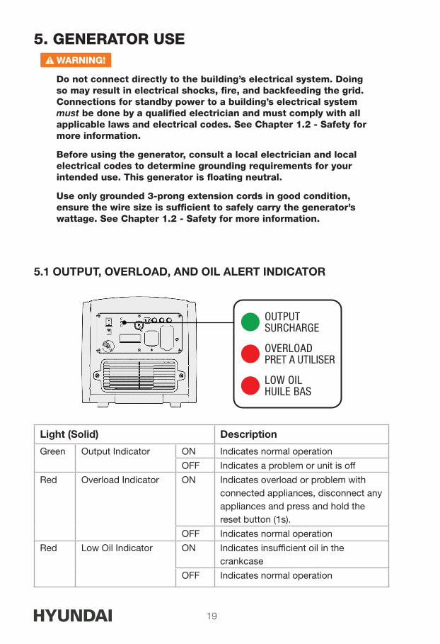
5.1 OUTPUT, OVERLOAD, AND OIL ALERT INDICATOR
Light (Solid) Description
Green Output Indicator ON Indicates normal operation
OFF Indicates a problem or unit is off
Red Overload Indicator ON Indicates overload or problem with connected appliances, disconnect any appliances and press and hold the reset button (1s).
OFF Indicates normal operation
Red Low Oil Indicator ON Indicates insufficient oil in the crankcase
OFF Indicates normal operation
OUTPUTSURCHARGE
OVERLOADPRET A UTILISER
LOW OILHUILE BAS

20
5.2 DC APPLICATIONS
The DC receptacle may be used for charging 12V batteries only. In DC operation, turn EcoMode OFF.
NOTE
The DC receptacle can be used while the AC power is in use. If used at the same time, be sure not to exceed the total power for AC and DC. (AC: Rated Running Watts, DC: 5A)
Motor vehicles require more than their rated wattage when starting.
Connecting the charging cable:
1. If connecting to a vehicle battery, disconnect the vehicle battery ground cable from the negative (-) battery terminals.
2. Connect the DC outlet to the battery terminals using the included charging cable. Connect red lead to positive (+) battery terminal and black lead to negative (-) battery terminal.
3. Turn EcoMode OFF, and start the generator.
NOTE
Do not start the vehicle engine when the generator is still connected to the battery, this will damage the generator.
System floating for DC output.
Disconnecting the charging cable:
1. Stop the engine.
2. Disconnect the black lead from the negative (-) battery terminal, and the red lead from the positive (+) battery terminal.
3. Reconnect the vehicle battery ground cable.
DC Charging Cable
HY SERIES
21
•••• •• •• •• •• ••
•••• •• •• •• •• ••
•••• •• •• •• •• ••
•• •• ••
•••• •• •• •• •• ••
•••• •• •• •• •• ••
•••• •• •• •• •• ••
•• •• ••
1 2 3 4
•••• •• •• •• •• ••
•••• •• •• •• •• ••
•••• •• •• •• •• ••
•• •• ••
•••• •• •• •• •• ••
•••• •• •• •• •• ••
•••• •• •• •• •• ••
•• •• ••
•••• •• •• •• •• ••
•••• •• •• •• •• ••
•••• •• •• •• •• ••
•• •• ••
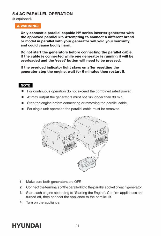
5.4 AC PARALLEL OPERATION(If equipped)
WARNING!
Only connect a parallel capable HY series inverter generator with the approved parallel kit. Attempting to connect a different brand or model in parallel with your generator will void your warranty and could cause bodily harm.
Do not start the generators before connecting the parallel cable. If the cable is connected while one generator is running it will be overloaded and the ‘reset’ button will need to be pressed.
If the overload indicator light stays on after resetting the generator stop the engine, wait for 5 minutes then restart it.
NOTE
For continuous operation do not exceed the combined rated power.
At max output the generators must not run longer than 30 min.
Stop the engine before connecting or removing the parallel cable.
For single unit operation the parallel cable must be removed.
1. Make sure both generators are OFF.
2. Connect the terminals of the parallel kit to the parallel socket of each generator.
3. Start each engine according to ‘Starting the Engine’. Confirm appliances are turned off, then connect the appliance to the parallel kit.
4. Turn on the appliance.

22
5.3 AC APPLICATIONS
1. Start engine and make sure output indicator light (READY TO USE) is on.
2. Confirm all electrical appliances are switched off, and connect the appliance plugs to the generator receptacle.
3. Turn on the appliances.
4. Turn EcoMode ON.
NOTE
Confirm all electrical appliances are in good working condition before connecting them to the generator. If an electrical appliance becomes abnormal, sluggish, or stops suddenly, shut off the generator engine immediately, and disconnect the appliance.
Most appliances require more than their rated wattage upon startup.
For continuous operation do not exceed the rated output of the generator.
The grounding system is not connected to the AC neutral wire.
Neutral floating for AC system.
OUTPUTSURCHARGE
OVERLOADPRET A UTILISER
LOW OILHUILE BAS
1 2 3 4
1 2 3
HY SERIES

23
6. STOPPING THE ENGINE
1. Switch off the connected electrical appliances.
2. Turn the power switch to the STOP position or press the OFF button on the remote control.
3. Turn the fuel shutoff to the CLOSED position.
NOTE
Make sure the fuel switch is in the CLOSED position when stopping, transporting, and storing the generator.
To stop the engine in an emergency, turn the power switch to STOP immediately.
OPEN
ON
ON
1 2 3
OPEN
START
1 2
OPEN1 2 3
3
STOP
CLOSED
1 2

24
7. MAINTENANCEProper maintenance keeps your generator in the best operating condition by ensuring safe, economical and trouble-free operation. Only use genuine parts and recommended fluids to replace the worn components. Improper maintenance may cause the generator to malfunction and can lead to serious injury. Contact customer support if you have any maintenance questions.
General Inspection Tips Look for fuel leaks around the fuel tank, fuel hose, and fuel valve. Close
the fuel valve and repair leaks immediately.
Look and listen for exhaust leaks while the engine is running. Have all the leaks repaired before continuing operation.
Check for dirt and debris and clean as necessary .
Check the engine oil level and add oil as necessary.
HY SERIES

25
7.1 MAINTENANCE SCHEDULE
Maintain the generator according to the maintenance schedule below.
NOTE
Service more frequently when used in dusty areas.
These items should be serviced by an authorized service center, unless you have the proper tools and are mechanically proficient. Refer to manual for service procedures.
Item TaskEachUse
First 10 Hours
Every 50
Hours
Every 100
Hours
Every 300
Hours
GeneratorGeneral Inspection
•
Engine Oil
Inspect Oil Level •
Change •* •**
Air FilterInspection •
Cleaning •
Sediment Cup
Cleaning •
Spark Plug
Inspection & Cleaning
•
Replacement •
Valve Clearance
Inspection & Adjusting
•
Combustion Chamber
Inspection & Adjusting
•
Fuel Tank and Strainer
Cleaning •
Fuel Line Cleaning Every two months (replace if necessary)
Exposed Metal Parts
Lubricate with oil After every use and especially before storage
* For first use of the generator.
**Change engine oil every 100 hours or yearly, whichever comes first.

26
7.2 CHANGING THE OIL
WARNING!
Used motor oil can cause skin irritations if left in long-term contact with skin. Thoroughly wash off used oil as soon as possible with soap and water.
Do not dispose of used oil in drains or on soil. Local service shops provide environmentally-friendly disposal methods.
Drain the oil rapidly and completely while the engine is still warm.
1. Loosen the screws of the oil maintenance cover and remove it, the bung, and the dipstick. Then place an oil collection pan under the oil drain bolt.
2. Remove the oil drain bolt.
3. Drain into the oil collection pan completely. Reinstall the oil drain bolt.
4. Check the oil level by reinserting the dipstick without rethreading it. Remove the dipstick and examine the oil level. If the level is at or below the minimum level, refill the oil to the maximum level mark.
5. Reinstall the oil dipstick and tighten it. Replace the rubber bung.
NOTE
Recommended oil volume to add: 18 fl. oz / 0.55L
SAE 10W-30 or Synthetic 5W-30 oil is recommended for general use.
Use of synthetic oil does not change maintenance intervals.
DO NOT OVERFILL.
OUTPUTSURCHARGE
OVERLOADPRET A UTILISER
LOW OILHUILE BAS
1 2 3 4
1 2 3
HY SERIES

27
NOTE
Do not tilt the generator when adding engine oil. This could result in
overfilling and damage to the engine.
Use high quality 4-stroke engine oil, certified to meet or exceed API standard SG, SF, SAE ratings with strong detergents. Using non-detergent or 2-stroke oil could shorten the engine’s working life.
Do not mix different engine oils.
Handle and store the engine oil with care, avoid getting dirt or dust into the engine oil.
Before the engine oil falls below the safety margin, the low oil alert system will automatically shut off the engine. The low oil light will turn on.
To avoid the inconvenience of unexpected engine shutoff, check the engine oil level as often as possible.
0°C 10 20 30 40 50-10-20-30
20 32°F 40 60 80 100 120
°C
°F0-20
15W-50
10W-30
Synthetic 5W-30
5W-30
Effective Viscosity Range of Engine Oils
Oil Cap and Dipstick Oil Capacity18 �. Oz. / 0.55L
Max Fill Level
Oil Transfer Tool

28
7.3 CLEANING THE AIR FILTER
WARNING!
Using gasoline or other flammable solvents can cause a fire or explosion. Do not operate this product without an air filter.
A dirty air filter will restrict air flow into the carburetor. Clean and maintain the air filter regularly, especially in dusty areas.
NOTE
Never run the generator without an air filter, doing so will quickly degrade the engine.
1. Unscrew and remove the air filter maintenance panel.
2. Unscrew and remove the air filter assembly.
3. Remove the foam filter.
Cover Screws
Air FilterMaintenance Panel
Air Filter
Air Filter Cover
HY SERIES

29
4. If the foam element is dirty, clean it in warm soapy water, rinse, and allow it to dry thoroughly, or clean in non-flammable solvent and allow to dry.
5. Dip the foam element in clean engine oil, then squeeze out all excess oil. The engine will smoke when started if too much oil is left in the filter.
6. Wipe dirt from the air filter assembly and reinstall into the unit.
7.4 SPARK PLUG SERVICE
NOTE
Do NOT rinse spark plug in water. Follow guidelines and be careful not to overtighten the spark plug.
Recommended spark plug: BP7ES (NGK)
Check the spark plug gap and clean the carbon deposits at the bottom of the spark plug.
Tighten 1/2 turn when installing a new spark plug.
Tighten 1/8 TO 1/4 turn when re-installing an old spark plug.
1. Remove the air filter access panel.
2. Remove the spark plug cap.
3. Remove the spark plug with the spark plug spanner.
4. Visually inspect the spark plug. Replace with a new one if the insulation is
Filter
0.60-0.70mm(0.024-0.028in)
Filter
0.60-0.70mm(0.024-0.028in)
Filter
0.60-0.70mm(0.024-0.028in)

30
cracked or chipped. Clean with a wire brush if the spark plug is reused.
5. Measure the spark plug gap with a feeler gauge. The normal value is: 0.6-0.7mm (0.024- 0.028in). Adjust the gap by carefully bending the electrode.
6. Carefully reinstall the spark plug by hand, to avoid cross-threading. A new spark plug should be tightened 1/2 turn with a spanner. A used spark plug should be tightened 1/8 to 1/4 turn with spanner.
7. Reinstall the spark plug cap.
8. Reinstall the spark plug maintenance cover.
NOTE
The spark plug must be securely tightened or it could cause the spark plug to heat up, enough to damage the engine.
Never use a spark plug with an improper heat range.
7.5 SPARK ARRESTER MAINTENANCE
1. Loosen the screws, and remove the handle and rear housing.
2. Take off the spark arrester from the muffler (after the engine has cooled down)
3. Use a brush to remove carbon deposits from the spark arrester. If the spark arrester is worn down, replace it.
4. Reinstall the spark arrester and muffler guard.
•••• •• •• •• •• ••
•••• •• •• •• •• ••
•••• •• •• •• •• ••
•• •• ••
•••• •• •• •• •• ••
•••• •• •• •• •• ••
•••• •• •• •• •• ••
•• •• ••
•••• •• •• •• •• ••
•••• •• •• •• •• ••
•••• •• •• •• •• ••
•• •• ••
•••• •• •• •• •• ••
•••• •• •• •• •• ••
•••• •• •• •• •• ••
•• •• ••
•••• •• •• •• •• ••
•••• •• •• •• •• ••
•••• •• •• •• •• ••
•• •• ••
3
1 2
•••• •• •• •• •• ••
•••• •• •• •• •• ••
•••• •• •• •• •• ••
•• •• ••
•••• •• •• •• •• ••
•••• •• •• •• •• ••
•••• •• •• •• •• ••
•• •• ••
•••• •• •• •• •• ••
•••• •• •• •• •• ••
•••• •• •• •• •• ••
•• •• ••
•••• •• •• •• •• ••
•••• •• •• •• •• ••
•••• •• •• •• •• ••
•• •• ••
•••• •• •• •• •• ••
•••• •• •• •• •• ••
•••• •• •• •• •• ••
•• •• ••
3
1 2
HY SERIES

31
7.6 REPLACING THE BATTERY
1. Loosen the screws of the battery maintenance cover, remove the cover.
2. Undo the battery bracket.
3. Locate the white connectors and unplug them to disconnect the battery.
4. Remove the battery from the tray and then remove both the negative and positive terminal connector screws, and attach them to the new battery.
5. Insert the new battery into the tray and fasten the battery bracket.
6. Re-connect the white connector then reinstall the battery maintenance cover.
NOTE
If the battery is dead, start the generator manually. The battery will charge while the engine is running.
The battery will slowly lose charge when left for long periods. For use with a trickle charging system, the charging current should be less than 0.15c amperes (c: battery rated capacity).
Fuel Cap
Fuel GaugeFuel Capacity2 gal. / 7.4L
Maximum Fuel Level
Battery Specifications
Voltage Capacity Dimension
L≤138mm
12V 7Ah W≤66mm
H≤88mm

32
7.7 FUEL FILTER MAINTENANCE
WARNING!
Gasoline is highly flammable and explosive under certain conditions. Refuel in a well-ventilated area with the engine stopped. Do not smoke or allow open flames or sparks in the area where the generator is being refueled or where gasoline is stored. Do not overfill the tank. Be careful not to spill fuel when refueling. Wipe up any spilled gasoline and let the area dry before starting the engine.
1. Remove the fuel cap and filter.
2. Clean the filter with solvent.
3. Wipe the filter.
4. Reinsert the filter.
•••• •• •• •• •• ••
•••• •• •• •• •• ••
•••• •• •• •• •• ••
•• •• ••
•••• •• •• •• •• ••
•••• •• •• •• •• ••
•••• •• •• •• •• ••
•• •• ••
1 2 3 4
•••• •• •• •• •• ••
•••• •• •• •• •• ••
•••• •• •• •• •• ••
•• •• ••
•••• •• •• •• •• ••
•••• •• •• •• •• ••
•••• •• •• •• •• ••
•• •• ••
•••• •• •• •• •• ••
•••• •• •• •• •• ••
•••• •• •• •• •• ••
•• •• ••
HY SERIES
33
7.8 EMISSION CONTROL SYSTEM
Emission Source
Exhaust gas contains carbon monoxide, nitrogen oxides (NOx) and hydrocarbons. It is very important to control the emissions of NOx and hydrocarbons as they are a major contributor to air pollution. Carbon monoxide is a poisonous gas. The emission of fuel vapors is a source of pollution as well. The generator engine utilizes a precise air-fuel ratio and emission control system to reduce the emissions of carbon monoxide, NOx, hydrocarbons and evaporative fuel emissions.
Regulation
Your engine has been designed to meet current Environmental Protection Agency (EPA) and the California Air Resource Board (CARB) clean air standards. The regulations dictate that the manufacturer provides operation and maintenance standards regarding the emission control systems. Tune up specifications are provided in the Specifications section and a description of the emission control system may be found in the appendix to this manual. Adherence to the following instruction will ensure your engine meets the emission control standards.
Modification
Modification of the emission control system may lead to increased emissions. Modification is defined as the following:
Disassembling or modifying the function or parts of the intake, fuel or exhaust system.
Modifying or destroying the speed governing function of the generator.
Engine faults that may affect emission
Any of the following faults must be repaired immediately. Consult with your authorized service centre for diagnosis and repair:
Hard starting or shut down after starting.
Unstable idle speed.
Shut down or backfire after applying an electrical load.
Backfire or after fire.
Black smoke and/or excessive fuel consumption.
34
Replacement parts and accessories
The parts making up the emission control system in your product’s engine have been specifically approved and certified by the regulatory agencies. You can trust that the replacement parts supplied by customer service have been manufactured to the same production standard as the original parts. The use of replacement parts or accessories which are not designed by – may negatively affect the engine emission performance. Therefore only use replacements parts and accessories from a qualified service centre to guarantee that the replacement products will not adversely affect emission performance.
Replacement parts other than those from an authorized service centre will void the warranty.
Air Index (Models certified for sale in California)
An Air Index Information label is applied to engines certified to an emission durability time period in accordance with the requirements of the California Air Resources Board.
The bar graph is intended to provide you, our customer, the ability to compare the emissions performance of available engines. The lower the Air Index, the less pollution.
The durability description is intended to provide you with information relating to the engine’s emission durability period. The descriptive term indicates the useful life period for the engine’s emission control system.
The Air Index information hang tag must remain on the generator until it is sold.Remove the hang tag before operating the generator.
HY SERIES
35
8. TRANSPORTATION & STORAGE
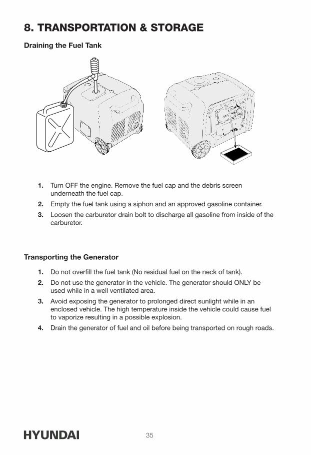
Draining the Fuel Tank
1. Turn OFF the engine. Remove the fuel cap and the debris screen underneath the fuel cap.
2. Empty the fuel tank using a siphon and an approved gasoline container.
3. Loosen the carburetor drain bolt to discharge all gasoline from inside of the carburetor.
Transporting the Generator
1. Do not overfill the fuel tank (No residual fuel on the neck of tank).
2. Do not use the generator in the vehicle. The generator should ONLY be used while in a well ventilated area.
3. Avoid exposing the generator to prolonged direct sunlight while in an enclosed vehicle. The high temperature inside the vehicle could cause fuel to vaporize resulting in a possible explosion.
4. Drain the generator of fuel and oil before being transported on rough roads.
36
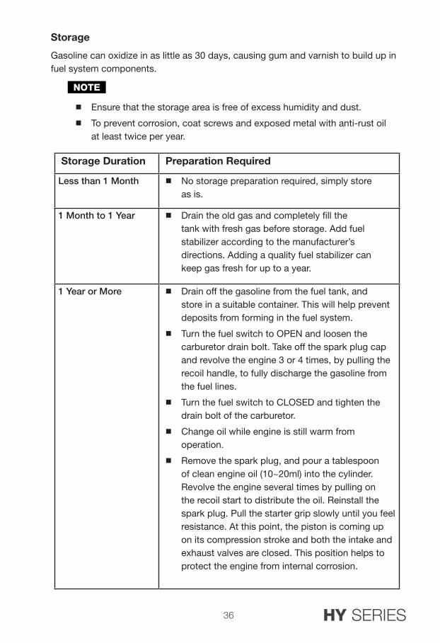
Storage
Gasoline can oxidize in as little as 30 days, causing gum and varnish to build up in fuel system components.
NOTE
Ensure that the storage area is free of excess humidity and dust.
To prevent corrosion, coat screws and exposed metal with anti-rust oil at least twice per year.
Storage Duration Preparation Required
Less than 1 Month No storage preparation required, simply store as is.
1 Month to 1 Year Drain the old gas and completely fill the tank with fresh gas before storage. Add fuel stabilizer according to the manufacturer’s directions. Adding a quality fuel stabilizer can keep gas fresh for up to a year.
1 Year or More Drain off the gasoline from the fuel tank, and store in a suitable container. This will help prevent deposits from forming in the fuel system.
Turn the fuel switch to OPEN and loosen the carburetor drain bolt. Take off the spark plug cap and revolve the engine 3 or 4 times, by pulling the recoil handle, to fully discharge the gasoline from the fuel lines.
Turn the fuel switch to CLOSED and tighten the drain bolt of the carburetor.
Change oil while engine is still warm from operation.
Remove the spark plug, and pour a tablespoon of clean engine oil (10~20ml) into the cylinder. Revolve the engine several times by pulling on the recoil start to distribute the oil. Reinstall the spark plug. Pull the starter grip slowly until you feel resistance. At this point, the piston is coming up on its compression stroke and both the intake and exhaust valves are closed. This position helps to protect the engine from internal corrosion.
HY SERIES
37
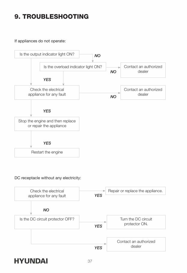
9. TROUBLESHOOTING
If appliances do not operate:
DC receptacle without any electricity:
NO
NO
NO
NO
YES
YES
YES
YES
YES
YES
Is the output indicator light ON?
Check the electrical appliance for any fault
Check the electrical appliance for any fault
Is the DC circuit protector OFF?
Stop the engine and then replace or repair the appliance
Repair or replace the appliance.
Turn the DC circuit protector ON.
Restart the engine
Is the overload indicator light ON? Contact an authorized dealer
Contact an authorized dealer
Contact an authorized dealer
38
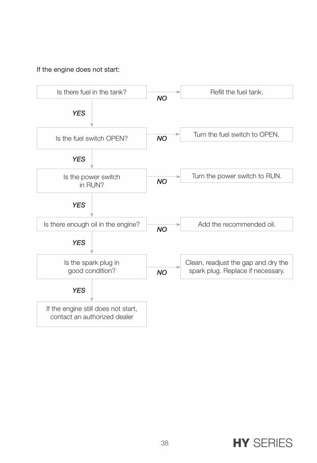
If the engine does not start:
NO
NO
NO
NO
NO
YES
YES
YES
YES
YES
Is there fuel in the tank?
Is the fuel switch OPEN?
Is the power switch in RUN?
Add the recommended oil.
Turn the power switch to RUN.
Clean, readjust the gap and dry the spark plug. Replace if necessary.
Is there enough oil in the engine?
Is the spark plug in good condition?
Turn the fuel switch to OPEN.
Refill the fuel tank.
If the engine still does not start, contact an authorized dealer
HY SERIES
39
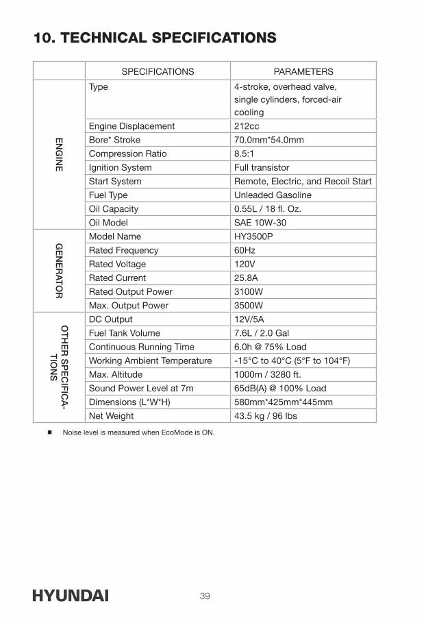
10. TECHNICAL SPECIFICATIONS
SPECIFICATIONS PARAMETERS
EN
GIN
E
Type 4-stroke, overhead valve, single cylinders, forced-air cooling
Engine Displacement 212cc
Bore* Stroke 70.0mm*54.0mm
Compression Ratio 8.5:1
Ignition System Full transistor
Start System Remote, Electric, and Recoil Start
Fuel Type Unleaded Gasoline
Oil Capacity 0.55L / 18 fl. Oz.
Oil Model SAE 10W-30
GE
NE
RAT
OR
Model Name HY3500P
Rated Frequency 60Hz
Rated Voltage 120V
Rated Current 25.8A
Rated Output Power 3100W
Max. Output Power 3500W
OT
HE
R S
PE
CIF
ICA
-T
ION
S
DC Output 12V/5A
Fuel Tank Volume 7.6L / 2.0 Gal
Continuous Running Time 6.0h @ 75% Load
Working Ambient Temperature -15°C to 40°C (5°F to 104°F)
Max. Altitude 1000m / 3280 ft.
Sound Power Level at 7m 65dB(A) @ 100% Load
Dimensions (L*W*H) 580mm*425mm*445mm
Net Weight 43.5 kg / 96 lbs
Noise level is measured when EcoMode is ON.

40
11. WIRING DIAGRAM
Ignition Module
AC
Rec
epta
cle
AC
Rec
epta
cle
Gro
und
Term
inal
Hou
rmet
er
Aux
. Win
ding
1
Aux
. W
indi
ng 2
Mai
n W
indi
ng
Bat
tery
12V
7 A
hIg
nitio
n W
indi
ngTr
igge
r W
arni
ngO
il S
enso
rS
park
P
lug
Igni
tion
Fuse
6A D
CR
eset
Ste
pper
Mot
or
20A
AC
Bre
aker
25A
AC
Bre
aker
ACTUATOR
INVERTER
BOOSTER PLATE
DC Connector
EC
ON
.
Fuel
Sw
itch
Ste
pper
Mot
or
HY SERIES

41
12. APPENDIXThe standard condition of rated power output:Altitude: 0mAmbient temperature: 77°F (25°C)Relative humidity: 30%
NOTE: Relative humidity 60% correction factor C-0.01Relative humidity 80% correction factor C -0.02Relative humidity 90% correction factor C-0.03Relative humidity 100% correction factor C-0.04
Example:
Rated power ( PN ) 2.8kVA generator (Altitude: 1000m) Ambient temperature: 35°C, Relative humidity: 80%
P=Pn*(C-0.02)=2.8*(0.82-0.02)=2.24kVA
Altitude (m) Ambient Temperature°F (°C)
77° (25°) 86° (30°) 95° (35°) 104° (40°) 113 (45°)
0 1 0.98 0.96 0.93 0.90
500 0.93 0.91 0.89 0.87 0.84
1000 0.87 0.85 0.82 0.80 0.78
2000 0.75 0.73 0.71 0.69 0.66
3000 0.64 0.62 0.60 0.58 0.56
4000 0.54 0.52 0.50 0.48 0.46
Factor of Environment Correction:

42 HY SERIES
13. LIMITED WARRANTY
Toll Free: 1-877-528-3772E-mail: [email protected]: www.hyundaipower.ca
Hyundai Power Equipment products are distributed by:Midland Power Inc.376 Magnetic Drive, Toronto, ON M3J 2C4, Canada
This product is warranted to be free of defects in material and workmanship for three years from date of purchase. This warranty guarantees that any defective parts will be repaired or replaced at no cost, including diagnosis and replacement parts.
Limited Warranty Periods
Recreational and Residential use: Three Years Limited 1st Year: Parts and Labor
2nd and 3rd Year: Parts only
Commercial use: 6 months limited, parts and labor
This limited warranty begins at the initial time of retail purchase and covers manufacturer’s defects caused by a defect in components or workmanship during the three (3) year period. The warranty coverage is continual from the initial date of purchase and does not restart at anytime under any circumstances. This limited warranty is valid for residential or recreational applications only and only when the generator receives all necessary preventative maintenance as described in the user guide.
The repair or replacement of a generator will take place within a reasonable period of time during normal business hours. All repair and replacement parts shall be warranted for (90) days after the initial date of installation or purchase.
Limitation of Remedies and Disclaimers
Midland International Inc. disclaims any responsibility for loss of time or use of the generator in a recreational vehicle or any vehicle in which the generator is installed, transportation, commercial loss, or any other incidental or consequential damage.Any implied warranties are limited to the duration of this written warranty.

43
THE FOREGOING LIMITED WARRANTY IS EXCLUSIVE OF AND IN LIEU
OF ALL OTHER WARRANTIES OF MERCHANTABILITY, FITNESS FOR A
PARTICULAR PURPOSE AND OF ANY OTHER WARRANTY WHETHER
EXPRESS OR IMPLIED.
Consumable parts, such as oil or fuel filters, fuel cut off valve, brushes, fuel injection nozzle valve, lubricant, or ignition plug, are not covered under this warranty. All expenses incurred in maintaining and replacing parts for generator shall fall on the purchaser. This warranty coverage does not include parts affected by accident and/or collision, corrosion or rust, normal wear, incorrect fuel type or fuel contamination, use in an application for which the product was not intended, unauthorized service, or any other misuse, neglect, incorporation or use of unsuitable attachments or parts. Damage to voltage regulators caused by failure to ground, shorting or overloading will not be covered under this warranty. Under this Warranty, we do not have the obligation to bear any transportation fees of any product to/from an authorized Warranty Center. Unauthorized alteration, installation or any cause other than defects in material or workmanship of the product will not be covered under the warranty.
Exclusions Not Covered by this Limited Warranty
Normal engine/alternator wear
Damage caused by lack of maintenance as described in the Hyundai User Guides, or negligence by using improper or impure motor oil, coolant, or fuel
Damage caused by accidents, improper installation or storage;
Damage caused by water ingestion, submersion, or external water damage
Damage or non-performance caused by operation of the generator set in a marine application
Damage caused by operation with improper fuel, or at speeds, loads, conditions, or modifications contrary to published specifications.
Items not supplied by Hyundai, including, but not limited to, starting batteries, battery cables, external wiring, fuel lines, filters, etc;(refer to exclusions)
Repairs made during the warranty period, without first obtaining a case number from Hyundai
44 HY SERIES
Batteries
Batteries supplied with any generator product should be considered a bonus item and not covered by warranty. Batteries can be damaged by shock, shorting terminals, heat, acid spillage and a number of other factors that cannot be controlled after they have left our facility. It is the customer’s responsibility to take great care when handling a battery so no spillage of acid will occur and cause corrosion; damage caused by battery acid is not covered under this warranty.
Our Warranty Rights and Obligations
California
The California Air Resources Board and Midland Power Inc. are pleased to explain the emission control system warranty on your Midland Power Inc. engine. In California, new spark-ignited small off-road equipment engines must be designed, built, and equipped to meet the State’s stringent anti-smog standards.
Other States, U.S. territories, and Canada
In other areas of the United States and in Canada, your engine must be designed, built, and equipped to meet the U.S. EPA and Environment Canada emission standards for spark-ignited engines at or below 19 kilowatts.
All of the United States and Canada
Midland Power Inc. must warrant the emission control system on your power equipment engine for the period of time listed below, provided there has been no abuse, neglect, or improper maintenance of your power equipment engine. Where a warrantable condition exists, Midland Power Inc. will repair your power equipment engine at no cost to you including diagnosis, parts, and labor.
Your emission control system may include such parts as the carburetor or fuel injection system, the ignition system, and catalytic converter. Also included may be hoses, connectors, and other emission-related assemblies.
45
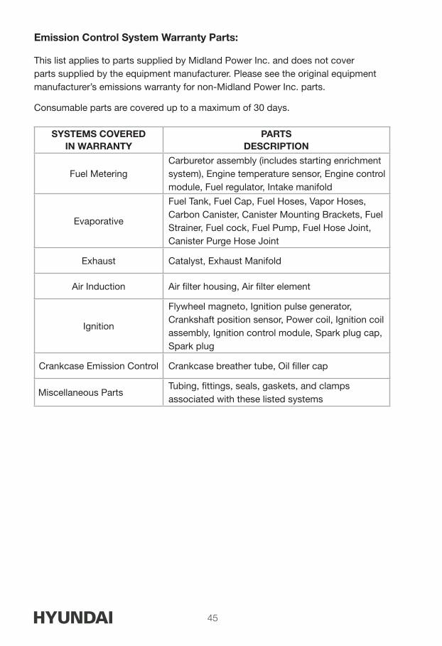
Emission Control System Warranty Parts:
This list applies to parts supplied by Midland Power Inc. and does not cover parts supplied by the equipment manufacturer. Please see the original equipment manufacturer’s emissions warranty for non-Midland Power Inc. parts.
Consumable parts are covered up to a maximum of 30 days.
SYSTEMS COVEREDIN WARRANTY
PARTSDESCRIPTION
Fuel MeteringCarburetor assembly (includes starting enrichment system), Engine temperature sensor, Engine control module, Fuel regulator, Intake manifold
Evaporative
Fuel Tank, Fuel Cap, Fuel Hoses, Vapor Hoses, Carbon Canister, Canister Mounting Brackets, Fuel Strainer, Fuel cock, Fuel Pump, Fuel Hose Joint, Canister Purge Hose Joint
Exhaust Catalyst, Exhaust Manifold
Air Induction Air filter housing, Air filter element
Ignition
Flywheel magneto, Ignition pulse generator, Crankshaft position sensor, Power coil, Ignition coil assembly, Ignition control module, Spark plug cap, Spark plug
Crankcase Emission Control Crankcase breather tube, Oil filler cap
Miscellaneous PartsTubing, fittings, seals, gaskets, and clamps associated with these listed systems

46 HY SERIES
Warranty Claim Procedure
Warranty service must be performed by one of our authorized service dealers. Do not return your product where purchased. If you feel your generator is malfunctioning due to a defect or misuse, simply contact our customer support center for technical advice, a warranty claim or general information. Warranty service, operation assistance and product support is provided by Midland Power Inc., contact us at the numbers below.
Product Registration Instructions
Product registration is required for product support and warranty coverage. You can register online at www.hyundaipower.ca. Once your registration is complete, your receipt will be on file and any future warranty claims will be easily created. If you wish, you can confirm your registration by calling customer service at 1-877-528-3772 or by e-mail at [email protected]
Proof of purchase may be required for warranty claims. Keep a copy of the original receipt, UPC code and serial number with this user guide.


HY SERIES
Enjoy!Be sure to check www.hyundaipower.ca for updates regarding your generator.

MASTER BACK
For Inquiries, Please Contact:
Midland Power Inc. 376 Magnetic Drive, Toronto, ON Canada M3J [email protected]
Distributed by Midland Power Inc., Canada Licensed by Hyundai Corporation, Korea