hvac | slide 1 of 47 2013 heating, ventilation and air- conditioning (hvac) part 2: air flows,...
TRANSCRIPT

HVAC | Slide 1 of 47 2013
Heating, Ventilation and Air-
Conditioning (HVAC)
Part 2: Air flows,
Pressure concepts
Good Manufacturing Practices: HVAC
WHO Technical Report Series, No. 961, 2011. Annex 5

HVAC | Slide 2 of 47 2013
HVACHVAC
Objectives
To continue from previous section of Part 1, now focus on:
Air filtration and air flow patterns
The role of HVAC in dust control
HVAC system design and its components (part 3)
Commissioning, qualification and maintenance (part 4)

HVAC | Slide 3 of 47 2013
HVACHVAC
Air Filtration
Degree of filtration of air is important to prevent contamination
Type of filters to be used is dependent on:– Quality of ambient air, – Return air / re-circulation– Air change rates– National requirements– Products and required class of clean room etc.
Manufacturer to determine, select and install appropriate filters for use 4.2.1, 4.3.3

HVAC | Slide 4 of 47 2013
HVACHVAC
Levels of protection and recommended filtration
4.2.1 - 2
Level of protection
Recommended filtration
Level 1Primary filters, e.g. EN779 G4
Level 2 Production area with 100% outside air: Primary plus secondary filter (e.g. EN779 G4 plus F8 or F9 filters)
Level 3Production facility operating on re-circulated plus ambient air, where potential for cross-contamination exists: Primary plus secondary plus tertiary filters (e.g. EN779 G4 plus F8 plus EN1822 H13 filters) (For full fresh air system, without recirculation, G4 and F8 or F9 filters are acceptable)

HVAC | Slide 5 of 47 2013
HVACHVAC
Contamination can be prevented by considering: Appropriate materials of construction of HVAC components
Placement of components (e.g. upstream of final filters)
Design and appropriate access (from outside) to dampers, filters and other components
Personnel operations and protection
Airflow direction
Air distribution component design, installation and location
Diffusers (type, design, location)
Air supply and air exhaust location4.2.4 – 4.2.10

HVAC | Slide 6 of 47 2013
HVACHVAC
Induction diffuserInduction diffuser

HVAC | Slide 7 of 47 2013
HVACHVAC
Perforated platePerforated plate

HVAC | Slide 8 of 47 2013
HVACHVAC
Swirl type diffuserSwirl type diffuser

HVAC | Slide 9 of 47 2013
HVAC
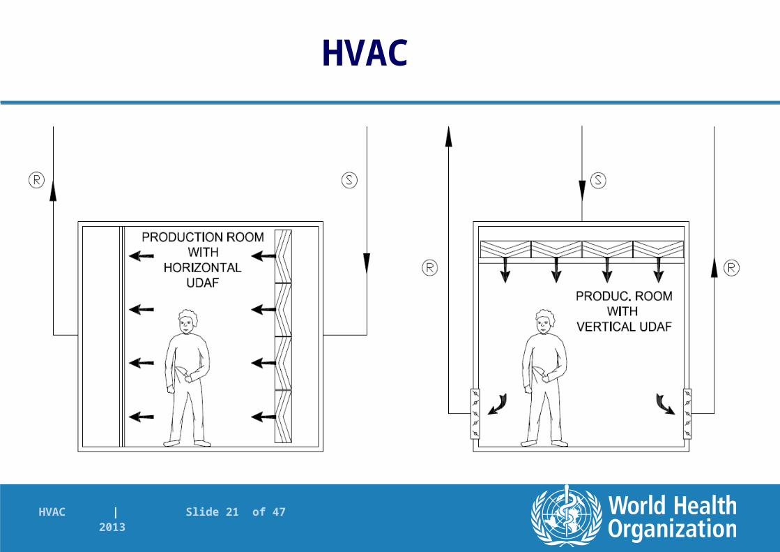
Airflow patterns
Filtered air entering a production room or covering a process can be
turbulent, or unidirectional (laminar)
GMP aspect economical aspect
Other technologies: barrier technology/isolator technology.

HVAC | Slide 10 of 47 2013
Unidirectional/laminar
displacement of dirty air
Turbulent
dilution of dirty air
Airflow patterns
HVAC

HVAC | Slide 11 of 47 2013
HVAC

HVAC | Slide 12 of 47 2013
PrefilterAirflow patterns
AHU
Main filter
Unidirectional TurbulentTurbulent
1 2 3
HVAC

HVAC | Slide 13 of 47 2013
HVACHVAC
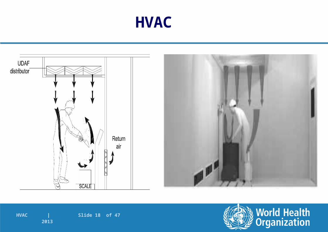
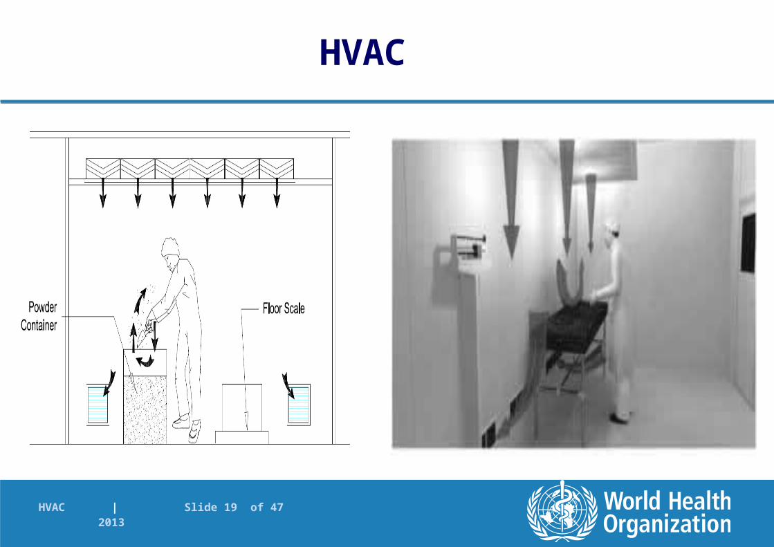
Unidirectional airflow (UDAF)
Often used in weighing and sampling areas (Airflow Protection Booths) and provides:
Dust containment and product and operator protection
Note: For Airflow Protection Booths (APB):
Airflow velocity should not affect balance (may be lower than for Class A areas)
Position of material, balance, operator determined and validated – no obstruction of airflow or risk 4.3

HVAC | Slide 14 of 47 2013
Workbench (vertical) Cabin/booth Ceiling
Airflow patterns
HVAC

HVAC | Slide 15 of 47 2013
HVACHVAC
Unidirectional airflow (UDAF): Sampling and weighing area classification – same as other
processing areas following sampling and dispensing
Dust containment shown through smoke tests as part of validation / qualification
Location and type of return and exhaust grilles
Cleaning and maintenance
Will discuss examples in the following figures
4.3.

HVAC | Slide 16 of 47 2013
HVAC

HVAC | Slide 17 of 47 2013
HVAC
HVAC | Slide 18 of 47 2013
HVAC
HVAC | Slide 19 of 47 2013
HVAC

HVAC | Slide 20 of 47 2013
HVAC
HVAC | Slide 21 of 47 2013
HVAC

HVAC | Slide 22 of 47 2013
HVAC

HVAC | Slide 23 of 47 2013

HVAC | Slide 24 of 47 2013
HVACHVAC
Infiltration
Prevent infiltration of unfiltered, contaminated air from outside
Facilities normally under positive pressure to the outside
Building structure well sealed
Some cases - negative pressure (e.g. penicillin manufacture). Special precautions to be taken. See separate guidelines
4.4.1 – 4.4.4

HVAC | Slide 25 of 47 2013
HVACHVAC
Cross-contamination
Multiproduct facility – even if in different areas - risk for cross contamination (dust from area to area)
Correct direction of air movement and pressure cascade
Normally, corridors positive to cubicles and cubicles positive to atmosphere
Consider building structure, ceilings, walls, doors etc
Different concepts discussed in following slides4.5

HVAC | Slide 26 of 47 2013
HVACHVAC
Displacement concept
Not a preferred method (Found in older facilities)
Based on low pressure differentials and high airflows
Air supplied to the corridor – then through the doors (grilles) to the cubicles
Air extracted at the back of the cubicle
Velocity high enough to prevent turbulence in doorway4.6

HVAC | Slide 27 of 47 2013
HVACHVAC
Pressure differential concept
Used where there is low dust in areas. Alone or in combination with other control techniques
High pressure differential, low airflow, and airlocks
Airlock types include: Cascade, sink and bubble type (See next slides)
Sufficient pressure differential required to ensure containment and prevent flow reversal – but not so high as to create turbulence
Consider effect of other items such as equipment and extraction systems in cubicles
4.7

HVAC | Slide 28 of 47 2013
HVACHVAC
Essential / critical parameter here is pressure differentials
Risk assessment may be done
High enough to achieve containment; low permissible when airlocks are used
No flow reversal should take place – therefore appropriate limits e.g. 5Pa to 20 Pa
No turbulence
No overlap (two adjacent rooms)
4.7

HVAC | Slide 29 of 47 2013
HVACHVAC
Adequate room pressure differential indication provided
Each critical room pressure must be traced back to ambient pressure (by summation of the room pressure differentials) – provides actual absolute pressure
Gauges with appropriate range and graduation scale to enable accurate reading; analogue or digital; as pressure differentials or absolute pressures
Normal operating range, alert and action limits defined and displayed
OOS condition should be easily identifiable4.7

HVAC | Slide 30 of 47 2013
N o te : D ire c t io n o f d o o r o p e n in g re la t iv e t o ro o m p re s s u re 1 5 P a1 5 P a1 5 P aE3 0 P a Pa s s a g e 0 P aA irLo ck R o o m 3 R o o m 2 R o o m 11 5 P a A ir Lo ckA ir Lo ck
HVAC

HVAC | Slide 31 of 47 2013
HVACHVAC
Calibrated and qualified monitoring devices, verified at intervals
Linked to alarm system
Monitoring and recording of results
Doors open to higher pressure, self closers
Doors interlocked where possible
4.7
HVAC | Slide 32 of 47 2013
HVACHVAC
Dust extraction system design is important as it may impact on pressure cascade
Central systems interlocked with AHUs
No airflow between rooms through common system
What happens in the case of component failure?
4.7
HVAC | Slide 33 of 47 2013
HVACHVAC
Airlocks and Material Pass-though-hatches (PTH)
Can be used to separate two zones
Dynamic and passive PTH
Also designed as bubble, sink or cascade
See next slides for design principles 4.7

HVAC | Slide 34 of 47 2013
HVACHVAC
HVAC | Slide 35 of 47 2013
HVACHVAC
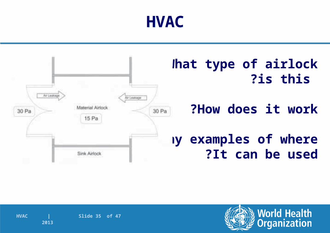
What type of airlock is this?
How does it work?
Any examples of whereIt can be used?

HVAC | Slide 36 of 47 2013
HVACHVAC
Physical barrier concept
In some cases, impervious barriers are used to prevent cross-contamination
Closed systems
Pump or vacuum transfer
4.8

HVAC | Slide 37 of 47 2013
HVACHVAC
Temperature and relative humidity (RH)
Consider materials and product requirements as well as operator comfort in the design of the HVAC
Where conditions are required, provide for control, monitoring and recording
Alert and action limits; minimum and maximum limits
Premises appropriately designed
HVAC design to achieve and maintain conditions in different seasons
4.9

HVAC | Slide 38 of 47 2013
HVACHVAC
Relative humidity (RH)
Low RH areas need well sealed walls and ceilings, and preferably air locks
Remove or add moisture as necessary
Dehumidification– Refrigerated dehumidifiers - cooling media– Chemical dehumidifiers
Humidifiers should not be sources of contamination
– Use of pure steam or clean steam
– No chemicals that can have a detrimental effect
4.9
HVAC | Slide 39 of 47 2013
HVACHVAC
Relative humidity (RH)
Humidifiers should be well drained - no accumulation of condensate
Avoid evaporative systems, atomizers, water-mist sprays
Suitable duct material
Insulation of cold surfaces
Air filters not immediately downstream of humidifiers
Chemical driers – used if not sources of contamination
4.9

HVAC | Slide 40 of 47 2013
Dust Control Where possible - dust and vapour
removed at source
Point of use extraction – fixed points or movable hood – plus general directional airflow in room
Ensure sufficient transfer velocity in extraction system to prevent dust settling in ducting
– Calculations and measurements
Periodic checks for build up
Risk analysis – airflow direction
5.1. – 5.6
HVACHVAC

HVAC | Slide 41 of 47 2013
HVACHVAC
Dust Control (2)
Normally air supplied through ceiling diffusers, near the door
Air extracted from low level (rear)
Extraction of vapours – consider density of vapour
Handling harmful products – additional steps needed– e.g. barrier technology, glove boxes
– totally enclosed garments with air-breathing systems
Fresh air rate supply– comfort, odour and fume removal, leakage, pressure control, etc.
5.7. – 5.8.

HVAC | Slide 42 of 47 2013
HVACHVAC

HVAC | Slide 43 of 47 2013
HVACHVAC

HVAC | Slide 44 of 47 2013
HVACHVAC

HVAC | Slide 45 of 47 2013
HVACHVAC

HVAC | Slide 46 of 47 2013
HVACHVAC
Dust collection system
Exhaust air dust
Exhaust air from equipment and some areas of production can carry heavy loads of dust, vapours and fumes (e.g. FBD, coating, weighing)
Filtration may be needed to protect environment (see National legislation)
Location of the inlet and exhaust points relative to one other important to prevent contaminants taken into inlet air
6.1.1 – 6.1.2
HVAC | Slide 47 of 47 2013
HVACHVAC
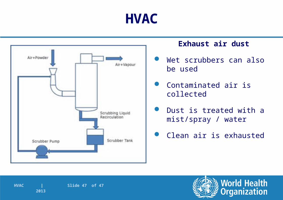
Exhaust air dust
Wet scrubbers can also be used
Contaminated air is collected
Dust is treated with a mist/spray / water
Clean air is exhausted