drm166, heating, ventilation, and air conditioning (hvac ... · heating, ventilation, and air...
TRANSCRIPT

Heating, Ventilation, and Air Conditioning (HVAC) Solution
Devices Supported:
MPC560xS, MPC5645S
Freescale Semiconductors Document Number: DRM166
Design Reference manual Rev. 0 , 08/2015

Heating, Ventilation, and Air Conditioning (HVAC) Solution Rev. 0, 08/2015
2 Freescale Semiconductor, Inc.
Heating, Ventilation, and Air Conditioning (HVAC) Solution Rev. 0, 08/2015
Freescale Semiconductor, Inc. 3
Table of Contents Introduction ........................................................................................................................................................ 5
1.1. Overview ................................................................................................................................................................... 5 1.2. Application Features and Components .................................................................................................................... 5
1.2.1. Basic Features ...................................................................................................................................................... 5 1.2.2. Advance Features ................................................................................................................................................. 6
1.3. MPC560xS/MPC5645S Controller Advantages and Features ................................................................................... 8
Hardware Description ....................................................................................................................................... 13
2.1. Introduction ............................................................................................................................................................ 13 2.2. Hardware Interfaces ............................................................................................................................................... 14
2.2.1. Power Supply Section ........................................................................................................................................ 15 2.2.2. Microcontroller and Associated Circuitry .......................................................................................................... 18 2.2.3. TFT LCD Interface ............................................................................................................................................... 28 2.2.4. Actuator Motor Interface ................................................................................................................................... 29 2.2.5. Blower Motor Interface ..................................................................................................................................... 29 2.2.6. Infra Red Interface ............................................................................................................................................. 30 2.2.7. Temperature Sensor Section ............................................................................................................................. 31 2.2.8. QSPI Section ....................................................................................................................................................... 31 2.2.9. Video Section ..................................................................................................................................................... 32 2.2.10. CAN Section ................................................................................................................................................... 32 2.2.11. LIN Section..................................................................................................................................................... 33 2.2.12. Audio Section ................................................................................................................................................ 33 2.2.13. RF Section ...................................................................................................................................................... 34 2.2.14. JTAG Section .................................................................................................................................................. 35
Software Design ................................................................................................................................................ 36
3.1. Introduction ............................................................................................................................................................ 36 3.2. Software Architecture ............................................................................................................................................ 36 3.3. Hardware Resource Allocation ............................................................................................................................... 37 3.4. Graphics .................................................................................................................................................................. 38
3.4.1. Overview ............................................................................................................................................................ 38 3.4.2. Movie Clips ......................................................................................................................................................... 38
3.5. User Interface ......................................................................................................................................................... 51 3.5.1. TFT Resistive Touch ............................................................................................................................................ 51 3.5.2. Infra Red remote control ................................................................................................................................... 52
3.6. Motor Drive ............................................................................................................................................................ 53 3.6.1. Blower Motor ..................................................................................................................................................... 53 3.6.2. Fresh Air Inlet Vent Control Motor .................................................................................................................... 53 3.6.3. Air Vent Position Control Motor ........................................................................................................................ 53 3.6.4. Hot /Cool Control Motor .................................................................................................................................... 54
3.7. Date and Real Time Clock ....................................................................................................................................... 54 3.8. Infra Red Control .................................................................................................................................................... 54 3.9. Temperature Sensor ............................................................................................................................................... 54
Testing and Measurements ............................................................................................................................... 55
4.1. Hardware Setup ...................................................................................................................................................... 55 4.2. Debugging and Measurement ................................................................................................................................ 55
4.2.1. LCD-TFT .............................................................................................................................................................. 56 4.2.2. User Interface .................................................................................................................................................... 57 4.2.3. Motor control..................................................................................................................................................... 60

Heating, Ventilation, and Air Conditioning (HVAC) Solution Rev. 0, 08/2015
4 Freescale Semiconductor, Inc.
4.3. Temperature sensor ............................................................................................................................................... 68
APPENDIX A Schematic and Layout ................................................................................................................................... 69
A.1 Schematic ............................................................................................................................................................... 69
APPENDIX B Bill of Material ............................................................................................................................................... 82
Heating, Ventilation, and Air Conditioning (HVAC) Solution Rev. 0, 08/2015
Freescale Semiconductor, Inc. 5
Introduction
1.1. Overview
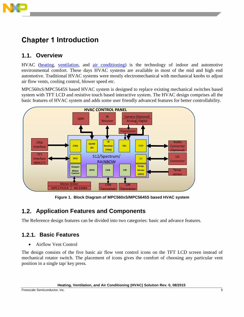
HVAC (heating, ventilation, and air conditioning) is the technology of indoor and automotive
environmental comfort. These days HVAC systems are available in most of the mid and high end
automotive. Traditional HVAC systems were mostly electromechanical with mechanical knobs to adjust
air flow vents, cooling control, blower speed etc.
MPC560xS/MPC5645S based HVAC system is designed to replace existing mechanical switches based
system with TFT LCD and resistive touch based interactive system. The HVAC design comprises all the
basic features of HVAC system and adds some user friendly advanced features for better controllability.
Figure 1. Block Diagram of MPC560xS/MPC5645S based HVAC system
1.2. Application Features and Components
The Reference design features can be divided into two categories: basic and advance features.
1.2.1. Basic Features
Airflow Vent Control
The design consists of the five basic air flow vent control icons on the TFT LCD screen instead of
mechanical rotator switch. The placement of icons gives the comfort of choosing any particular vent
position in a single tap/ key press.

Heating, Ventilation, and Air Conditioning (HVAC) Solution Rev. 0, 08/2015
6 Freescale Semiconductor, Inc.
Blower Speed Control (5 Level)
A five stage blower speed selection is provided on the screen. On tapping/key press an enlarged screen
pops up to ease the selection even from rear-seat. The speed control could be implemented as analog
control with very fine step size but is currently limited to five steps for comfort of user in switching
from mechanical systems to advanced TFT LCD based systems.
Cool/Warm Control
An analog slider is implemented for the cooling control. On tapping/button press, similar to speed
control, cooling control slider also enlarges and eases the selection. The analog slider is kept analogues
to slider control in traditional mechanical systems but step size can be reduced to a much larger extent in
advanced system.
Defogger On/Off
Recirculation On/Off
Air Conditioning On/Off
Defoggers, Recirculation, AC on/off icons are implemented as toggle switch for respective
functionalities.
1.2.2. Advance Features
In order to take the HVAC technology further closer to comfort and luxury various advanced features
are implemented in the design.
Four pre-defined intuitive profiles
User defined profile(s)
A typical HVAC system requires multiple inputs from user every time user turns on the system. These
inputs are mainly driven from the climate condition at that time. Moreover, once the outside climate
changes HVAC system needs to be reconfigured. To save the user from this activity time and again the
advance HVAC design consist of four pre-defined profiles. These profiles can be intuitively chosen
based on climate condition. These profiles are named as Sunny, Partly Cloudy, Cloudy and Rainy. Each
profile automatically configures the HVAC system based on its predefined parameter. User is allowed to
make changes in HVAC control even when a particular profile is selected. However there is another
profile defined as “User” profile for customized settings. Once the settings are made after entering the
user profile, settings will be saved and will be recalled on revisiting the profile. The profile auto saves
the settings on each exit of the user profile.
Cabin temperature display
Date display
Time display
There is a cabin temperature display on the screen which gets the feed from temperature sensor. The
design displays and maintains date and time information. The clock provided is of fair accuracy as per
automotive standards. A user friendly GUI allows the setting of date and time in case of system
powered-up for the first time or battery is re-installed.
Heating, Ventilation, and Air Conditioning (HVAC) Solution Rev. 0, 08/2015
Freescale Semiconductor, Inc. 7
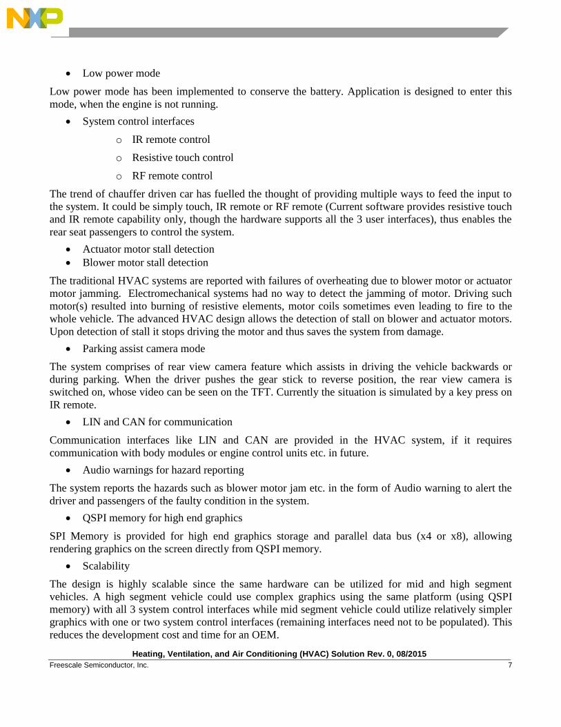
Low power mode
Low power mode has been implemented to conserve the battery. Application is designed to enter this
mode, when the engine is not running.
System control interfaces
o IR remote control
o Resistive touch control
o RF remote control
The trend of chauffer driven car has fuelled the thought of providing multiple ways to feed the input to
the system. It could be simply touch, IR remote or RF remote (Current software provides resistive touch
and IR remote capability only, though the hardware supports all the 3 user interfaces), thus enables the
rear seat passengers to control the system.
Actuator motor stall detection
Blower motor stall detection
The traditional HVAC systems are reported with failures of overheating due to blower motor or actuator
motor jamming. Electromechanical systems had no way to detect the jamming of motor. Driving such
motor(s) resulted into burning of resistive elements, motor coils sometimes even leading to fire to the
whole vehicle. The advanced HVAC design allows the detection of stall on blower and actuator motors.
Upon detection of stall it stops driving the motor and thus saves the system from damage.
Parking assist camera mode
The system comprises of rear view camera feature which assists in driving the vehicle backwards or
during parking. When the driver pushes the gear stick to reverse position, the rear view camera is
switched on, whose video can be seen on the TFT. Currently the situation is simulated by a key press on
IR remote.
LIN and CAN for communication
Communication interfaces like LIN and CAN are provided in the HVAC system, if it requires
communication with body modules or engine control units etc. in future.
Audio warnings for hazard reporting
The system reports the hazards such as blower motor jam etc. in the form of Audio warning to alert the
driver and passengers of the faulty condition in the system.
QSPI memory for high end graphics
SPI Memory is provided for high end graphics storage and parallel data bus (x4 or x8), allowing
rendering graphics on the screen directly from QSPI memory.
Scalability
The design is highly scalable since the same hardware can be utilized for mid and high segment
vehicles. A high segment vehicle could use complex graphics using the same platform (using QSPI
memory) with all 3 system control interfaces while mid segment vehicle could utilize relatively simpler
graphics with one or two system control interfaces (remaining interfaces need not to be populated). This
reduces the development cost and time for an OEM.
Heating, Ventilation, and Air Conditioning (HVAC) Solution Rev. 0, 08/2015
8 Freescale Semiconductor, Inc.
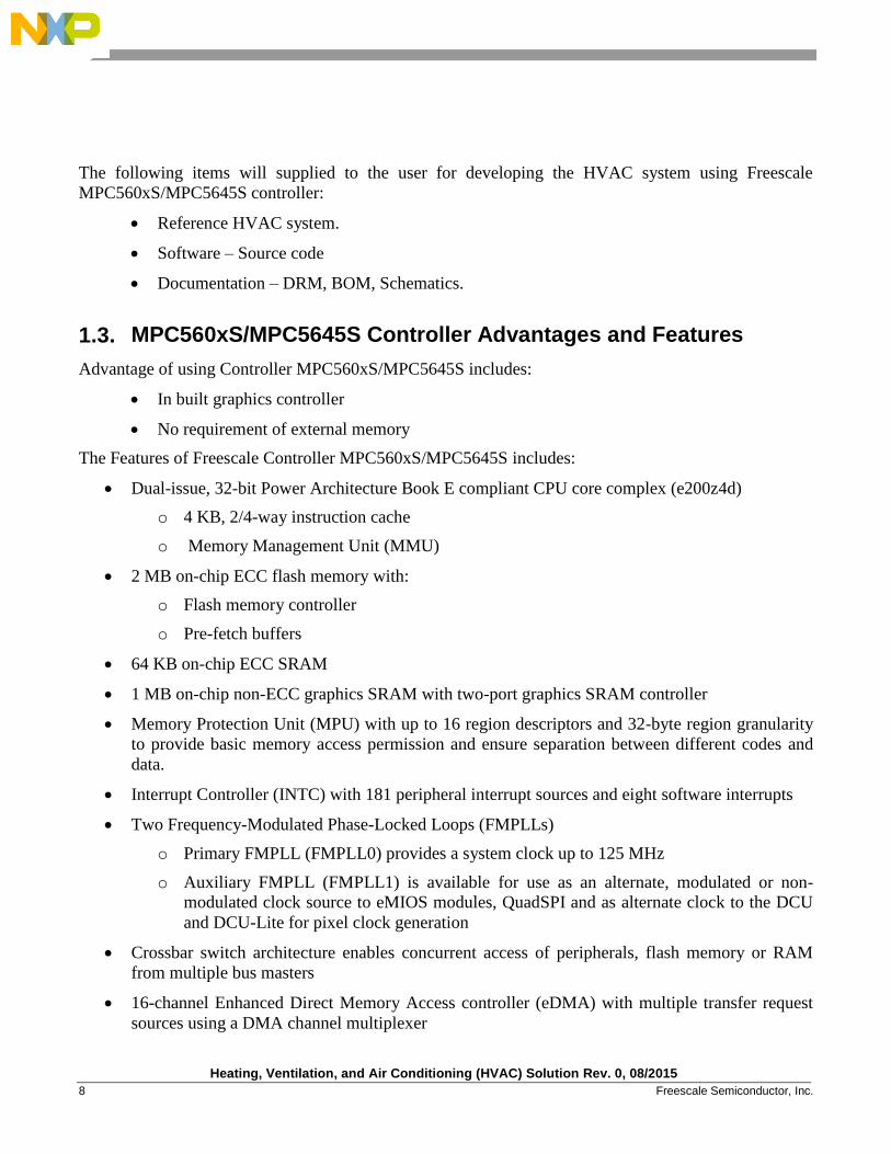
The following items will supplied to the user for developing the HVAC system using Freescale
MPC560xS/MPC5645S controller:
Reference HVAC system.
Software – Source code
Documentation – DRM, BOM, Schematics.
1.3. MPC560xS/MPC5645S Controller Advantages and Features
Advantage of using Controller MPC560xS/MPC5645S includes:
In built graphics controller
No requirement of external memory
The Features of Freescale Controller MPC560xS/MPC5645S includes:
Dual-issue, 32-bit Power Architecture Book E compliant CPU core complex (e200z4d)
o 4 KB, 2/4-way instruction cache
o Memory Management Unit (MMU)
2 MB on-chip ECC flash memory with:
o Flash memory controller
o Pre-fetch buffers
64 KB on-chip ECC SRAM
1 MB on-chip non-ECC graphics SRAM with two-port graphics SRAM controller
Memory Protection Unit (MPU) with up to 16 region descriptors and 32-byte region granularity
to provide basic memory access permission and ensure separation between different codes and
data.
Interrupt Controller (INTC) with 181 peripheral interrupt sources and eight software interrupts
Two Frequency-Modulated Phase-Locked Loops (FMPLLs)
o Primary FMPLL (FMPLL0) provides a system clock up to 125 MHz
o Auxiliary FMPLL (FMPLL1) is available for use as an alternate, modulated or non-
modulated clock source to eMIOS modules, QuadSPI and as alternate clock to the DCU
and DCU-Lite for pixel clock generation
Crossbar switch architecture enables concurrent access of peripherals, flash memory or RAM
from multiple bus masters
16-channel Enhanced Direct Memory Access controller (eDMA) with multiple transfer request
sources using a DMA channel multiplexer
Heating, Ventilation, and Air Conditioning (HVAC) Solution Rev. 0, 08/2015
Freescale Semiconductor, Inc. 9
Boot Assist Module (BAM) with 8 KB dedicated ROM for embedded boot code supports boot
options including download of boot code via a serial link (CAN or SCI)
Two Display Control Units (DCU3 and DCULite) for direct drive of up to two TFT LCD
displays up to XGA resolution
Timing Controller (TCON) and RSDS interface for the DCU3 module
2D OpenVG 1.1 and raster graphics accelerator (GFX2D)
Video Input Unit (VIU2) supporting 8/10-bit ITU656 video input, YUV to RGB conversion,
video down-scaling, de-interlacing, contrast adjustment and brightness adjustment.
DRAM controller supporting DDR1, DDR2, LPDDR1 and SDR DRAMs
Stepper Motor Controller (SMC)
High-current drivers for up to six instrument cluster gauges driven in full dual H-bridge
configuration
o Stepper motor return-to-zero and stall detection module
o Stepper motor short circuit detection
Sound Generator Module (SGM)
o 4-channel mixer
o Supports PCM wave playback and synthesized tones
o Optional PWM or I2S outputs
Two 16-channel Enhanced Modular Input Output System (eMIOS) modules
Support a range of 16-bit Input Capture, Output Compare, Pulse Width Modulation and
Quadrature Decode functions
10-bit Analog-to-Digital Converter (ADC) with a maximum conversion time of 1 microsec
o Up to 20 internal channels
o Up to 8 external channels
Three Deserial Serial Peripheral Interface (DSPI) modules for full-duplex, synchronous,
communications with external devices
QuadSPI serial flash memory controller
o Supports single, dual and quad IO serial flash memory
o Interfaces to external, memory-mapped serial flash memories
o Supports simultaneous addressing of two external serial flashes to achieve up 80 MB/s
read bandwidth
RLE decoder supporting memory to memory decoding of RLE data in conjunction with eDMA
Heating, Ventilation, and Air Conditioning (HVAC) Solution Rev. 0, 08/2015
10 Freescale Semiconductor, Inc.
Four local interconnect network (LINFlex) controller modules
o Capable of autonomous message handling (master), autonomous header handling (slave
mode), and UART support
o Compliant with LIN protocol rev 2.1
Three controller-area network (FlexCAN) modules
o Compliant with the CAN protocol version 2.0 C
o 64 configurable buffers
o Programmable bit rate of up to 1 Mb/s
Four Inter-Integrated Circuit (I2C) internal bus controllers with master/slave bus interface
Low-power loop controlled pierce crystal oscillator supporting 4–16MHz external crystal or
resonator
Real Time Counter (RTC) with clock source from internal 128 kHz or 16 MHz oscillator
supporting autonomous wake-up with 1 ms resolution with maximum timeout of 2 seconds
o Support for real time counter (RTC) with clock source from external 32 KHz crystal
oscillator, supporting wake-up with 1 s resolution and maximum timeout of one hour
o RTC optionally clocked by fast 4–16 MHz external oscillator
System timers:
o Four-channel 32-bit System Timer Module (STM)
o Eight-channel 32-bit Periodic Interrupt Timer (PIT) module (including ADC trigger)
o Software Watchdog Timer (SWT)
System Integration Unit Lite (SIUL) module to manage external interrupts, GPIO and pad
control
System Status and Configuration Module (SSCM)
o Provides information for identification of the device, last boot mode, or debug status
o Provides an entry point for the censorship password mechanism
Clock Generation Module (MC_CGM) to generate system clock sources and provide a unified
register interface, enabling access to all clock sources
Clock Monitor Unit (CMU)
o Monitors the integrity of the fast (4–16 MHz) external crystal oscillator and the primary
FMPLL (FMPLL0)
o Acts as a frequency meter, measuring the frequency of one clock source and comparing it
to a reference clock
Heating, Ventilation, and Air Conditioning (HVAC) Solution Rev. 0, 08/2015
Freescale Semiconductor, Inc. 11
Mode Entry Module (MC_ME)
o Controls the device power mode, i.e., RUN, HALT, STOP, or STANDBY
o Controls mode transition sequences
o Manages the power control, voltage regulator, clock generation and clock management
modules
Power Control Unit (MC_PCU) to implement standby mode entry/exit and control connections
to power domains
Reset Generation Module (MC_RGM) to manage reset assertion and release to the device at
initial power-up
Nexus Development Interface (NDI) per IEEE-ISTO 5001-2008 Class 3 standard with additional
Class 4 features:
o Watchpoint Triggering
o Processor Overrun Control
Device/board boundary-scan testing supported per Joint Test Action Group (JTAG) of IEEE
(IEEE 1149.1)
On-chip voltage regulator controller for regulating the 3.3-5 V supply voltage down to 1.2 V for
core logic (requires external ballast transistor)
Package:
o 176 LQFP, 0.5 mm pitch, 24 mm x 24 mm outline
o 208 LQFP, 0.5 mm pitch, 28 mm x 28 mm outline
o 416 TEPBGA, 1mm ball pitch, 27 mm x 27 mm outline
Heating, Ventilation, and Air Conditioning (HVAC) Solution Rev. 0, 08/2015
12 Freescale Semiconductor, Inc.
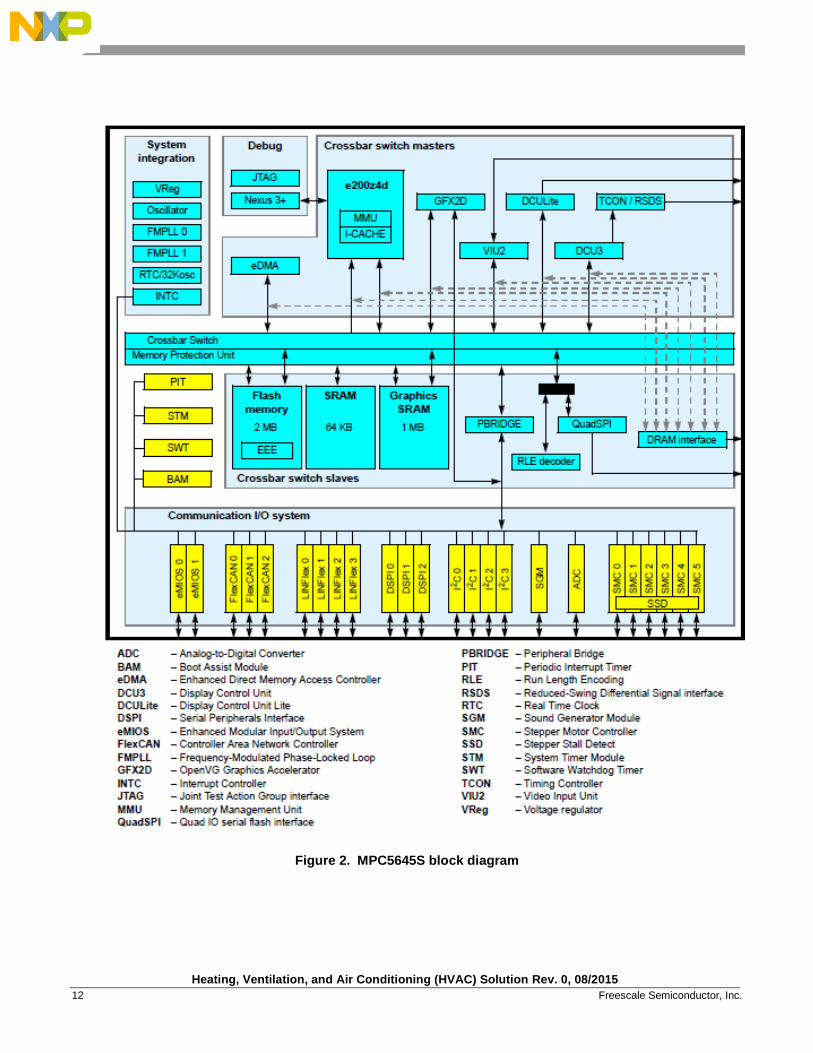
Figure 2. MPC5645S block diagram
Heating, Ventilation, and Air Conditioning (HVAC) Solution Rev. 0, 08/2015
Freescale Semiconductor, Inc. 13
Hardware Description
2.1. Introduction
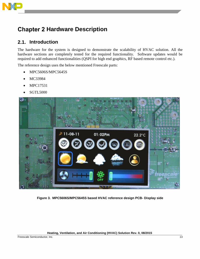
The hardware for the system is designed to demonstrate the scalability of HVAC solution. All the
hardware sections are completely tested for the required functionality. Software updates would be
required to add enhanced functionalities (QSPI for high end graphics, RF based remote control etc.).
The reference design uses the below mentioned Freescale parts:
MPC5606S/MPC5645S
MC33984
MPC17531
SGTL5000
Figure 3. MPC5606S/MPC5645S based HVAC reference design PCB- Display side
Heating, Ventilation, and Air Conditioning (HVAC) Solution Rev. 0, 08/2015
14 Freescale Semiconductor, Inc.
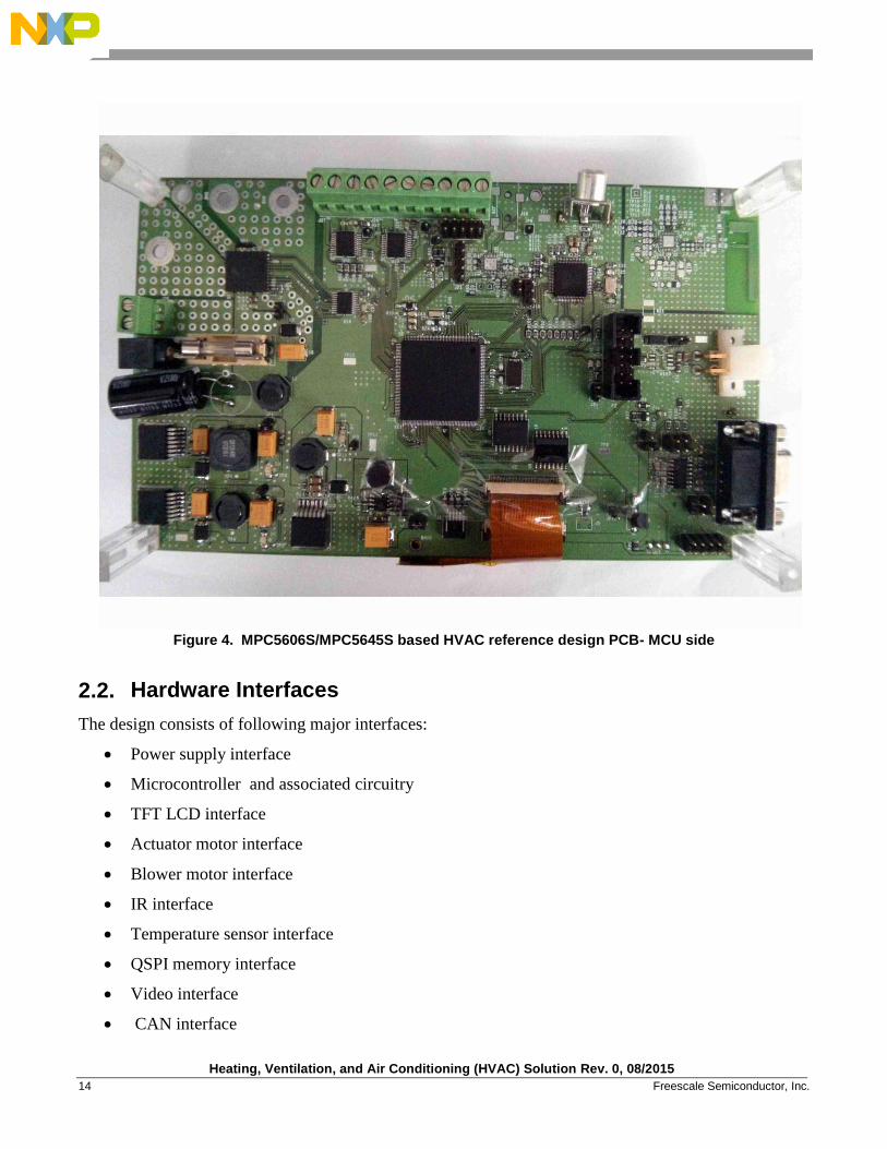
Figure 4. MPC5606S/MPC5645S based HVAC reference design PCB- MCU side
2.2. Hardware Interfaces
The design consists of following major interfaces:
Power supply interface
Microcontroller and associated circuitry
TFT LCD interface
Actuator motor interface
Blower motor interface
IR interface
Temperature sensor interface
QSPI memory interface
Video interface
CAN interface
Heating, Ventilation, and Air Conditioning (HVAC) Solution Rev. 0, 08/2015
Freescale Semiconductor, Inc. 15
LIN interface
Audio interface
RF interface
JTAG interface
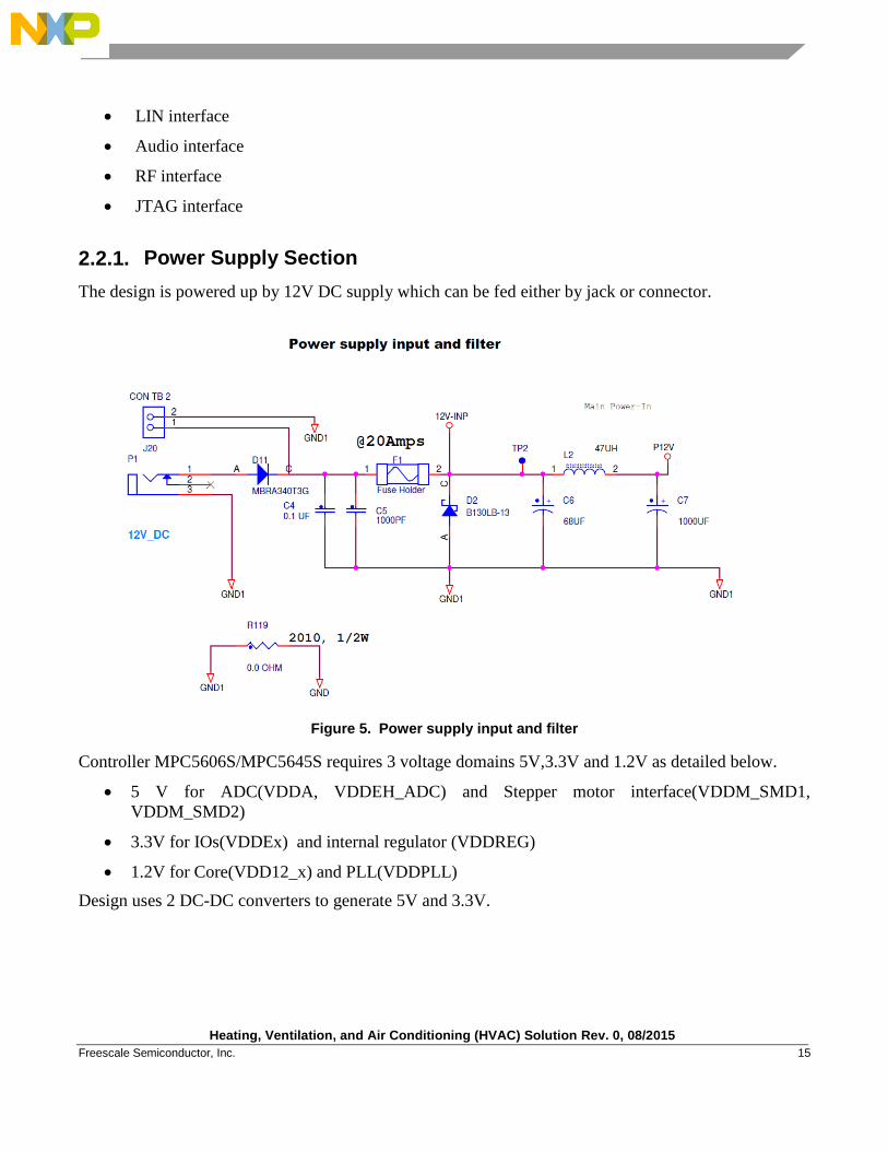
2.2.1. Power Supply Section
The design is powered up by 12V DC supply which can be fed either by jack or connector.
Figure 5. Power supply input and filter
Controller MPC5606S/MPC5645S requires 3 voltage domains 5V,3.3V and 1.2V as detailed below.
5 V for ADC(VDDA, VDDEH_ADC) and Stepper motor interface(VDDM_SMD1,
VDDM_SMD2)
3.3V for IOs(VDDEx) and internal regulator (VDDREG)
1.2V for Core(VDD12_x) and PLL(VDDPLL)
Design uses 2 DC-DC converters to generate 5V and 3.3V.
Heating, Ventilation, and Air Conditioning (HVAC) Solution Rev. 0, 08/2015
16 Freescale Semiconductor, Inc.
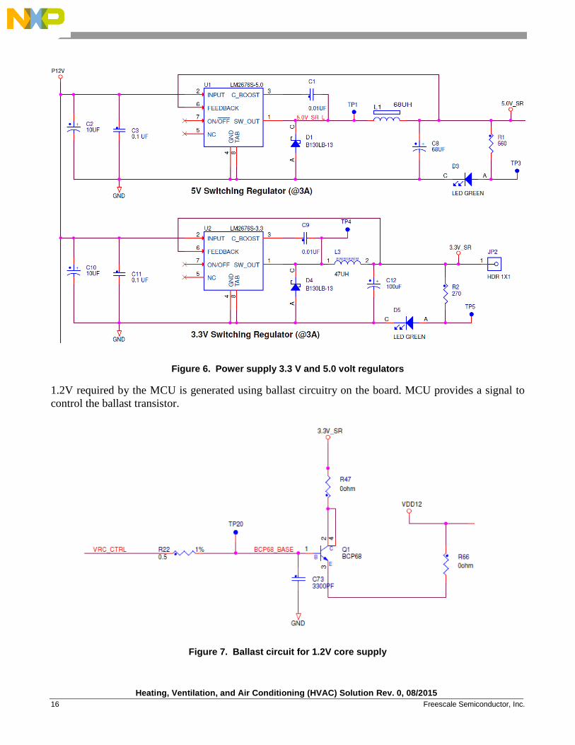
Figure 6. Power supply 3.3 V and 5.0 volt regulators
1.2V required by the MCU is generated using ballast circuitry on the board. MCU provides a signal to
control the ballast transistor.
Figure 7. Ballast circuit for 1.2V core supply
Heating, Ventilation, and Air Conditioning (HVAC) Solution Rev. 0, 08/2015
Freescale Semiconductor, Inc. 17
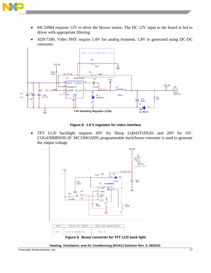
MC33984 requires 12V to drive the blower motor. The DC 12V input to the board is fed to
driver with appropriate filtering.
ADV7180, Video PHY require 1.8V for analog frontend. 1.8V is generated using DC-DC
converter.
Figure 8. 1.8 V regulator for video interface
TFT LCD backlight requires 30V for Sharp LQ043T1DG01 and 20V for OT-
COG430MBWH-1P. MC33063ADG programmable buck/boost converter is used to generate
the output voltage.
Figure 9. Boost converter for TFT LCD back light
Heating, Ventilation, and Air Conditioning (HVAC) Solution Rev. 0, 08/2015
18 Freescale Semiconductor, Inc.
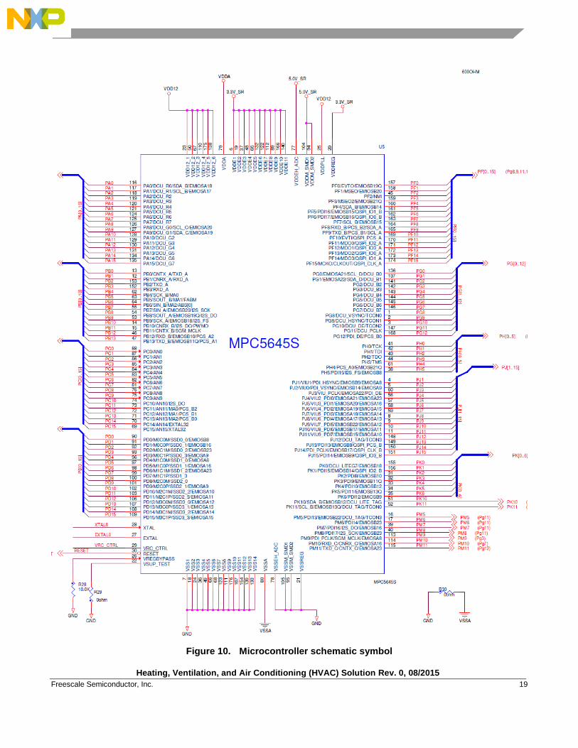
2.2.2. Microcontroller and Associated Circuitry
MPC5645S/MPC5606S is a power PC core based controller having multiple voltage domains (IO
voltage, core voltage). It offers 3.3 V and 5.0 V compatible IOs, which can be customized for
appropriate voltage as per system requirement.
MCU utilizes the following interfaces in the design:
Display Control Unit(DCU) to drive 480x272 TFT LCD
ADC to interface with resistive touch panel
Stepper Motor Controller(SMC) to drive Actuators motors
Enhanced Modular IO Subsystem (eMIOS) to drive blower motor
ADC to detect stall on blower and actuator motors
ADC to interface with temperature sensor
eMIOS for IR remote capability
De-serial Serial Peripheral Interface (DSPI) interface for RF support
JTAG for programming.
Quad Serial Peripheral Interface (QSPI) for QSPI memory
Sound Generator Module(SGM) and IIC for Audio support
Video Input Unit(VIU) and IIC for Video support
LIN and CAN interface for communication with other electronic units
Heating, Ventilation, and Air Conditioning (HVAC) Solution Rev. 0, 08/2015
Freescale Semiconductor, Inc. 19
Figure 10. Microcontroller schematic symbol
Heating, Ventilation, and Air Conditioning (HVAC) Solution Rev. 0, 08/2015
20 Freescale Semiconductor, Inc.
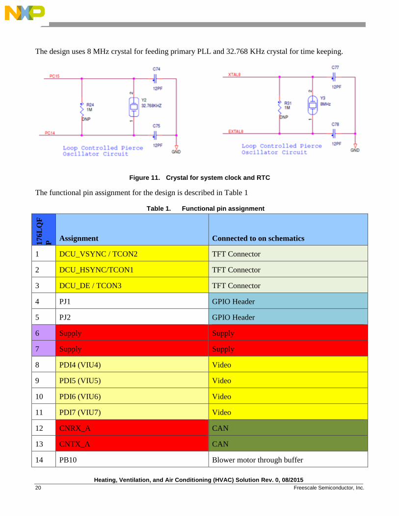
The design uses 8 MHz crystal for feeding primary PLL and 32.768 KHz crystal for time keeping.
Figure 11. Crystal for system clock and RTC
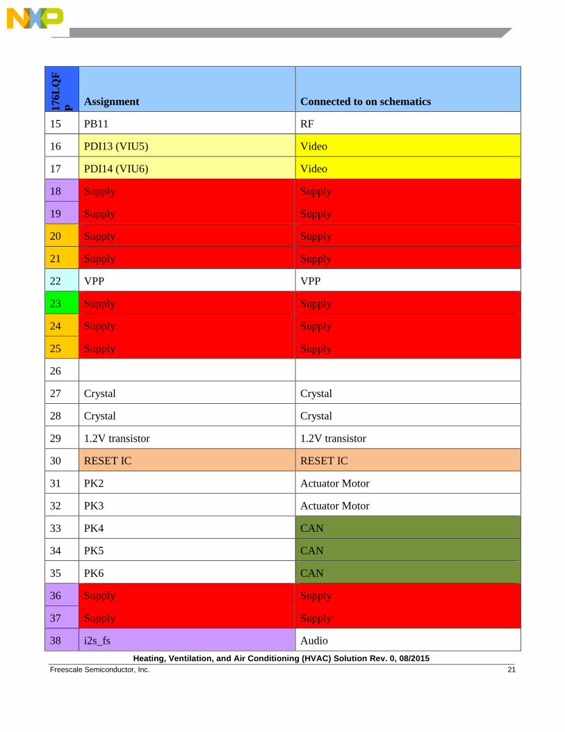
The functional pin assignment for the design is described in Table 1
Table 1. Functional pin assignment
176L
QF
P Assignment Connected to on schematics
1 DCU_VSYNC / TCON2 TFT Connector
2 DCU_HSYNC/TCON1 TFT Connector
3 DCU_DE / TCON3 TFT Connector
4 PJ1 GPIO Header
5 PJ2 GPIO Header
6 Supply Supply
7 Supply Supply
8 PDI4 (VIU4) Video
9 PDI5 (VIU5) Video
10 PDI6 (VIU6) Video
11 PDI7 (VIU7) Video
12 CNRX_A CAN
13 CNTX_A CAN
14 PB10 Blower motor through buffer
Heating, Ventilation, and Air Conditioning (HVAC) Solution Rev. 0, 08/2015
Freescale Semiconductor, Inc. 21
176L
QF
P Assignment Connected to on schematics
15 PB11 RF
16 PDI13 (VIU5) Video
17 PDI14 (VIU6) Video
18 Supply Supply
19 Supply Supply
20 Supply Supply
21 Supply Supply
22 VPP VPP
23 Supply Supply
24 Supply Supply
25 Supply Supply
26
27 Crystal Crystal
28 Crystal Crystal
29 1.2V transistor 1.2V transistor
30 RESET IC RESET IC
31 PK2 Actuator Motor
32 PK3 Actuator Motor
33 PK4 CAN
34 PK5 CAN
35 PK6 CAN
36 Supply Supply
37 Supply Supply
38 i2s_fs Audio
Heating, Ventilation, and Air Conditioning (HVAC) Solution Rev. 0, 08/2015
22 Freescale Semiconductor, Inc.
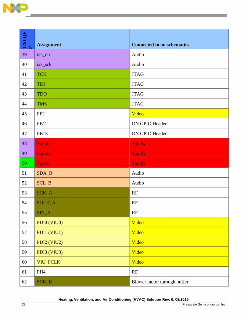
176L
QF
P Assignment Connected to on schematics
39 i2s_do Audio
40 i2s_sck Audio
41 TCK JTAG
42 TDI JTAG
43 TDO JTAG
44 TMS JTAG
45 PF2 Video
46 PB12 ON GPIO Header
47 PB13 ON GPIO Header
48 Supply Supply
49 Supply Supply
50 Supply Supply
51 SDA_B Audio
52 SCL_B Audio
53 SCK_A RF
54 SOUT_A RF
55 SIN_A RF
56 PDI0 (VIU0) Video
57 PDI1 (VIU1) Video
58 PDI2 (VIU2) Video
59 PDI3 (VIU3) Video
60 VIU_PCLK Video
61 PH4 RF
62 SCK_B Blower motor through buffer
Heating, Ventilation, and Air Conditioning (HVAC) Solution Rev. 0, 08/2015
Freescale Semiconductor, Inc. 23
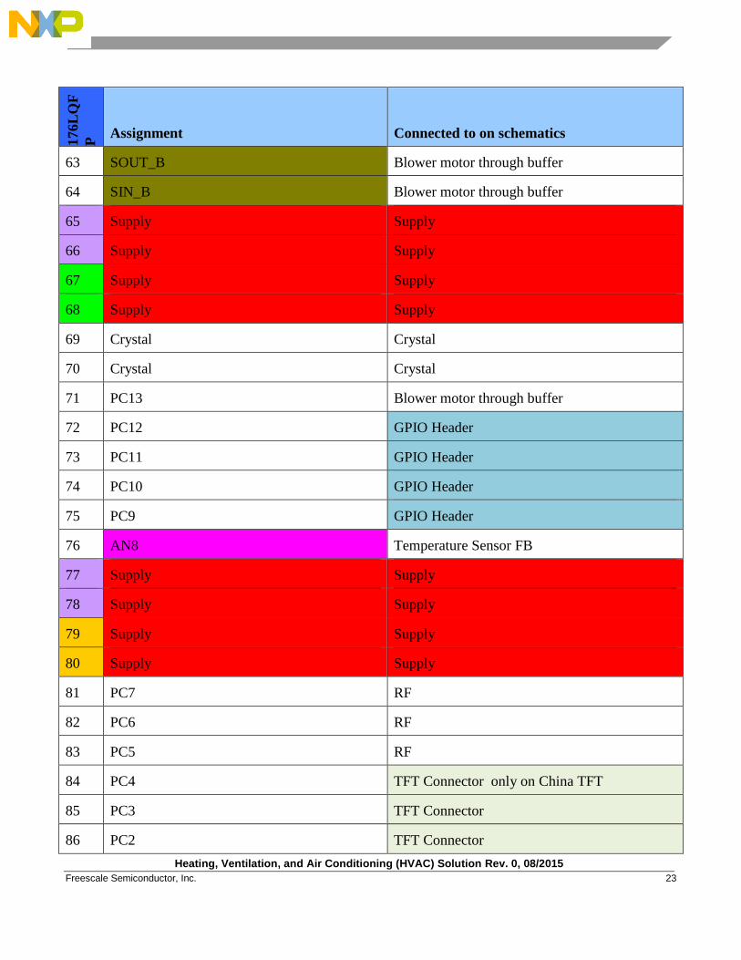
176L
QF
P Assignment Connected to on schematics
63 SOUT_B Blower motor through buffer
64 SIN_B Blower motor through buffer
65 Supply Supply
66 Supply Supply
67 Supply Supply
68 Supply Supply
69 Crystal Crystal
70 Crystal Crystal
71 PC13 Blower motor through buffer
72 PC12 GPIO Header
73 PC11 GPIO Header
74 PC10 GPIO Header
75 PC9 GPIO Header
76 AN8 Temperature Sensor FB
77 Supply Supply
78 Supply Supply
79 Supply Supply
80 Supply Supply
81 PC7 RF
82 PC6 RF
83 PC5 RF
84 PC4 TFT Connector only on China TFT
85 PC3 TFT Connector
86 PC2 TFT Connector
Heating, Ventilation, and Air Conditioning (HVAC) Solution Rev. 0, 08/2015
24 Freescale Semiconductor, Inc.
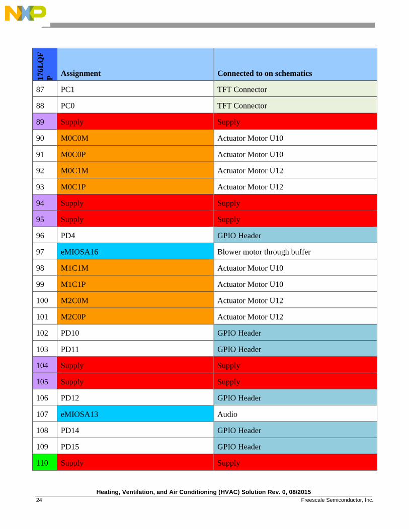
176L
QF
P Assignment Connected to on schematics
87 PC1 TFT Connector
88 PC0 TFT Connector
89 Supply Supply
90 M0C0M Actuator Motor U10
91 M0C0P Actuator Motor U10
92 M0C1M Actuator Motor U12
93 M0C1P Actuator Motor U12
94 Supply Supply
95 Supply Supply
96 PD4 GPIO Header
97 eMIOSA16 Blower motor through buffer
98 M1C1M Actuator Motor U10
99 M1C1P Actuator Motor U10
100 M2C0M Actuator Motor U12
101 M2C0P Actuator Motor U12
102 PD10 GPIO Header
103 PD11 GPIO Header
104 Supply Supply
105 Supply Supply
106 PD12 GPIO Header
107 eMIOSA13 Audio
108 PD14 GPIO Header
109 PD15 GPIO Header
110 Supply Supply
Heating, Ventilation, and Air Conditioning (HVAC) Solution Rev. 0, 08/2015
Freescale Semiconductor, Inc. 25
176L
QF
P Assignment Connected to on schematics
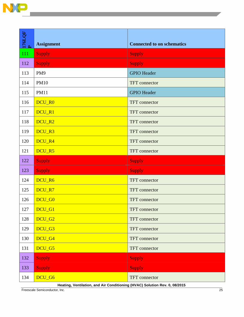
111 Supply Supply
112 Supply Supply
113 PM9 GPIO Header
114 PM10 TFT connector
115 PM11 GPIO Header
116 DCU_R0 TFT connector
117 DCU_R1 TFT connector
118 DCU_R2 TFT connector
119 DCU_R3 TFT connector
120 DCU_R4 TFT connector
121 DCU_R5 TFT connector
122 Supply Supply
123 Supply Supply
124 DCU_R6 TFT connector
125 DCU_R7 TFT connector
126 DCU_G0 TFT connector
127 DCU_G1 TFT connector
128 DCU_G2 TFT connector
129 DCU_G3 TFT connector
130 DCU_G4 TFT connector
131 DCU_G5 TFT connector
132 Supply Supply
133 Supply Supply
134 DCU_G6 TFT connector
Heating, Ventilation, and Air Conditioning (HVAC) Solution Rev. 0, 08/2015
26 Freescale Semiconductor, Inc.
176L
QF
P Assignment Connected to on schematics
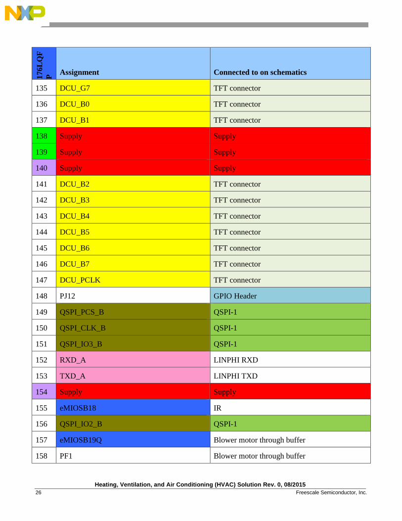
135 DCU_G7 TFT connector
136 DCU_B0 TFT connector
137 DCU_B1 TFT connector
138 Supply Supply
139 Supply Supply
140 Supply Supply
141 DCU_B2 TFT connector
142 DCU_B3 TFT connector
143 DCU_B4 TFT connector
144 DCU_B5 TFT connector
145 DCU_B6 TFT connector
146 DCU_B7 TFT connector
147 DCU_PCLK TFT connector
148 PJ12 GPIO Header
149 QSPI_PCS_B QSPI-1
150 QSPI_CLK_B QSPI-1
151 QSPI_IO3_B QSPI-1
152 RXD_A LINPHI RXD
153 TXD_A LINPHI TXD
154 Supply Supply
155 eMIOSB18 IR
156 QSPI_IO2_B QSPI-1
157 eMIOSB19Q Blower motor through buffer
158 PF1 Blower motor through buffer
Heating, Ventilation, and Air Conditioning (HVAC) Solution Rev. 0, 08/2015
Freescale Semiconductor, Inc. 27
176L
QF
P Assignment Connected to on schematics
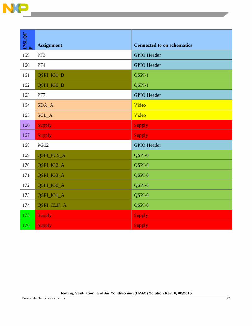
159 PF3 GPIO Header
160 PF4 GPIO Header
161 QSPI_IO1_B QSPI-1
162 QSPI_IO0_B QSPI-1
163 PF7 GPIO Header
164 SDA_A Video
165 SCL_A Video
166 Supply Supply
167 Supply Supply
168 PG12 GPIO Header
169 QSPI_PCS_A QSPI-0
170 QSPI_IO2_A QSPI-0
171 QSPI_IO3_A QSPI-0
172 QSPI_IO0_A QSPI-0
173 QSPI_IO1_A QSPI-0
174 QSPI_CLK_A QSPI-0
175 Supply Supply
176 Supply Supply
Heating, Ventilation, and Air Conditioning (HVAC) Solution Rev. 0, 08/2015
28 Freescale Semiconductor, Inc.
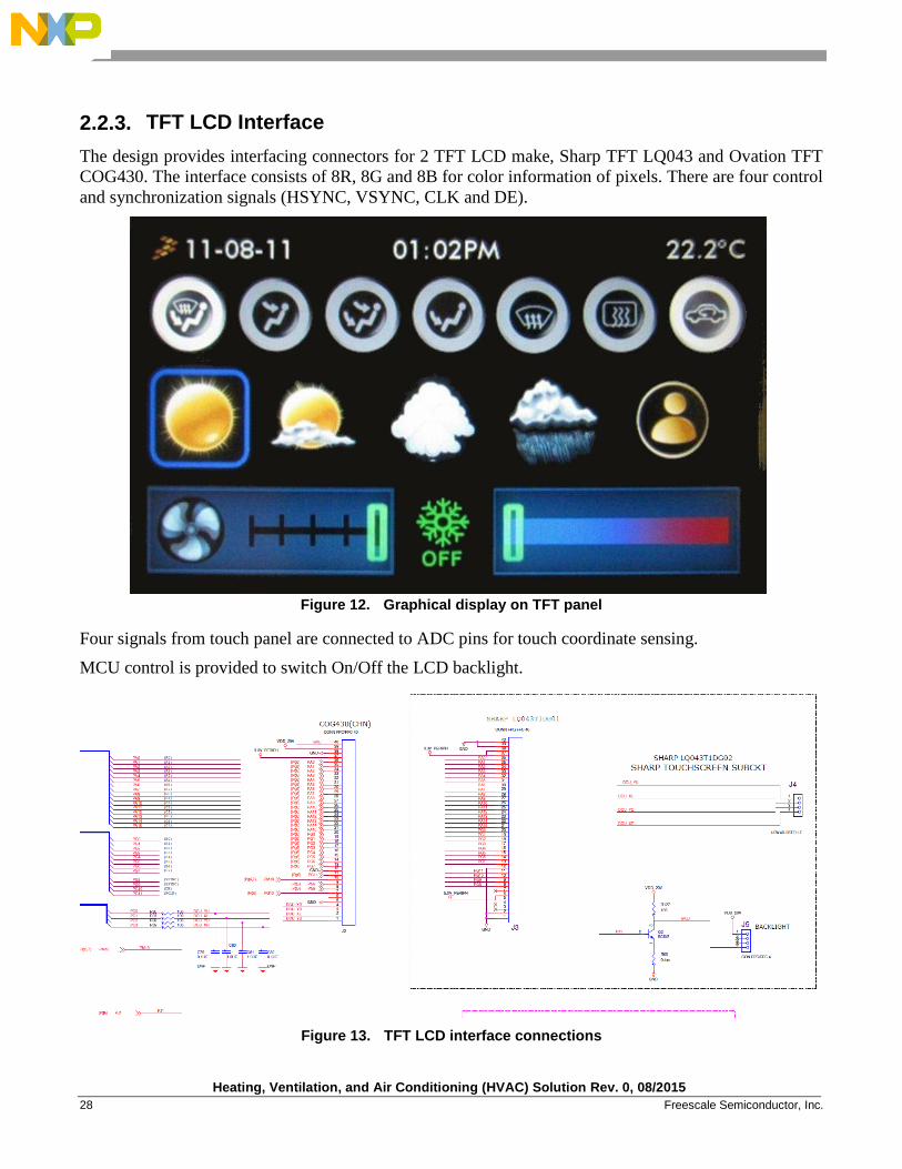
2.2.3. TFT LCD Interface
The design provides interfacing connectors for 2 TFT LCD make, Sharp TFT LQ043 and Ovation TFT
COG430. The interface consists of 8R, 8G and 8B for color information of pixels. There are four control
and synchronization signals (HSYNC, VSYNC, CLK and DE).
Figure 12. Graphical display on TFT panel
Four signals from touch panel are connected to ADC pins for touch coordinate sensing.
MCU control is provided to switch On/Off the LCD backlight.
Figure 13. TFT LCD interface connections
Heating, Ventilation, and Air Conditioning (HVAC) Solution Rev. 0, 08/2015
Freescale Semiconductor, Inc. 29
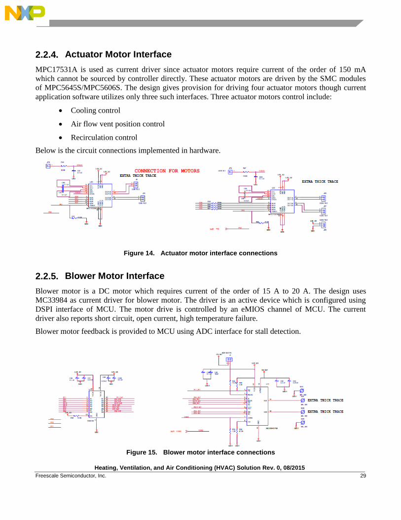
2.2.4. Actuator Motor Interface
MPC17531A is used as current driver since actuator motors require current of the order of 150 mA
which cannot be sourced by controller directly. These actuator motors are driven by the SMC modules
of MPC5645S/MPC5606S. The design gives provision for driving four actuator motors though current
application software utilizes only three such interfaces. Three actuator motors control include:
Cooling control
Air flow vent position control
Recirculation control
Below is the circuit connections implemented in hardware.
Figure 14. Actuator motor interface connections
2.2.5. Blower Motor Interface
Blower motor is a DC motor which requires current of the order of 15 A to 20 A. The design uses
MC33984 as current driver for blower motor. The driver is an active device which is configured using
DSPI interface of MCU. The motor drive is controlled by an eMIOS channel of MCU. The current
driver also reports short circuit, open current, high temperature failure.
Blower motor feedback is provided to MCU using ADC interface for stall detection.
Figure 15. Blower motor interface connections
Heating, Ventilation, and Air Conditioning (HVAC) Solution Rev. 0, 08/2015
30 Freescale Semiconductor, Inc.
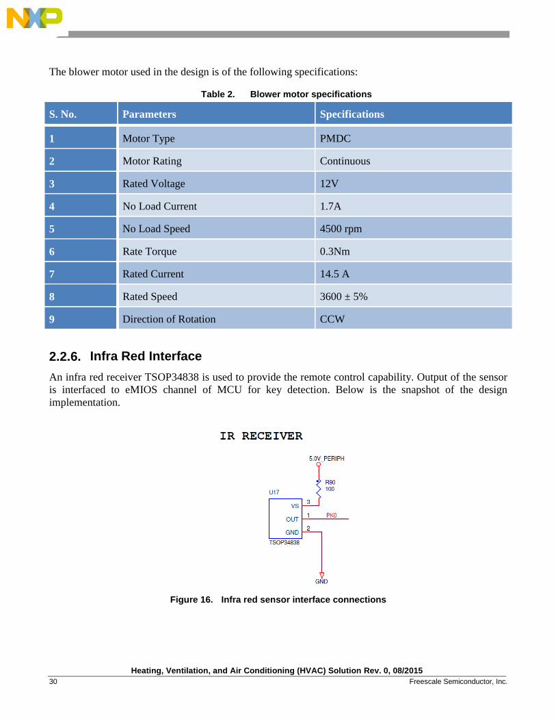
The blower motor used in the design is of the following specifications:
Table 2. Blower motor specifications
S. No. Parameters Specifications
1 Motor Type PMDC
2 Motor Rating Continuous
3 Rated Voltage 12V
4 No Load Current 1.7A
5 No Load Speed 4500 rpm
6 Rate Torque 0.3Nm
7 Rated Current 14.5 A
8 Rated Speed 3600 ± 5%
9 Direction of Rotation CCW
2.2.6. Infra Red Interface
An infra red receiver TSOP34838 is used to provide the remote control capability. Output of the sensor
is interfaced to eMIOS channel of MCU for key detection. Below is the snapshot of the design
implementation.
Figure 16. Infra red sensor interface connections

Heating, Ventilation, and Air Conditioning (HVAC) Solution Rev. 0, 08/2015
Freescale Semiconductor, Inc. 31
2.2.7. Temperature Sensor Section
Temperature sensor LM94022 is interfaced to the ADC channel of MCU. The sensor provides the
voltage which is used to calculate the ambient temperature based on a pre-defined table in the sensor
manual. Sensor output needs to be calibrated to obtain the best results. Below is the interface
connection.
Figure 17. Temperature sensor interface connections
2.2.8. QSPI Section
QSPI memory is provided to provide the non volatile memory to the system apart from internal flash. It
is interfaced to the QSPI controller in parallel mode to achieve better throughput. Below is the snapshot
of the interface connections.
Figure 18. QSPI interface connections
Heating, Ventilation, and Air Conditioning (HVAC) Solution Rev. 0, 08/2015
32 Freescale Semiconductor, Inc.
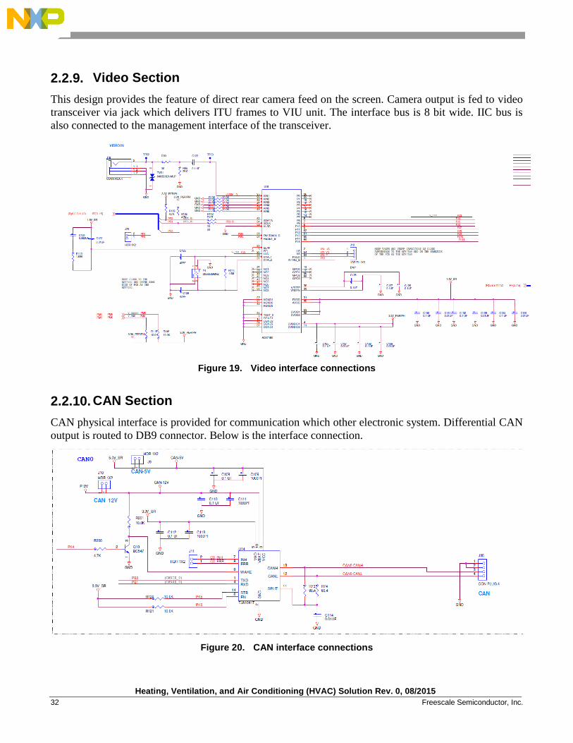
2.2.9. Video Section
This design provides the feature of direct rear camera feed on the screen. Camera output is fed to video
transceiver via jack which delivers ITU frames to VIU unit. The interface bus is 8 bit wide. IIC bus is
also connected to the management interface of the transceiver.
Figure 19. Video interface connections
2.2.10. CAN Section
CAN physical interface is provided for communication which other electronic system. Differential CAN
output is routed to DB9 connector. Below is the interface connection.
Figure 20. CAN interface connections
Heating, Ventilation, and Air Conditioning (HVAC) Solution Rev. 0, 08/2015
Freescale Semiconductor, Inc. 33
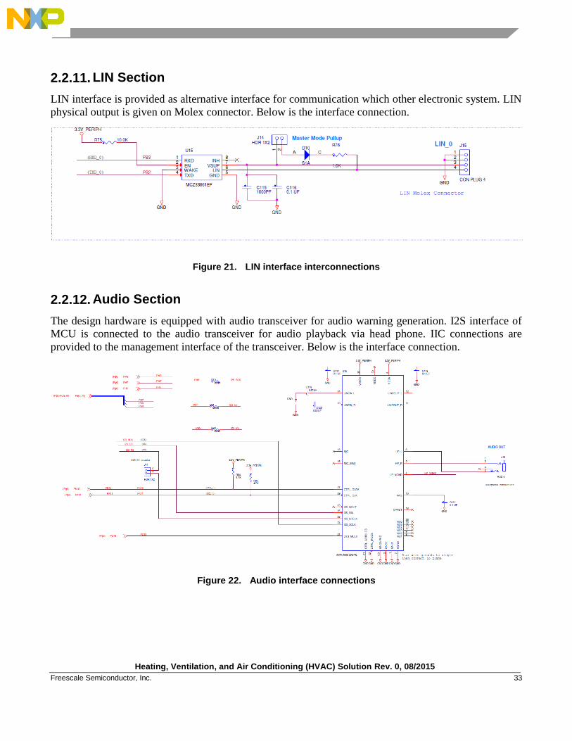
2.2.11. LIN Section
LIN interface is provided as alternative interface for communication which other electronic system. LIN
physical output is given on Molex connector. Below is the interface connection.
Figure 21. LIN interface interconnections
2.2.12. Audio Section
The design hardware is equipped with audio transceiver for audio warning generation. I2S interface of
MCU is connected to the audio transceiver for audio playback via head phone. IIC connections are
provided to the management interface of the transceiver. Below is the interface connection.
Figure 22. Audio interface connections
Heating, Ventilation, and Air Conditioning (HVAC) Solution Rev. 0, 08/2015
34 Freescale Semiconductor, Inc.
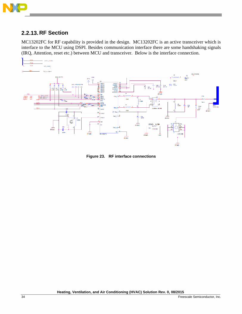
2.2.13. RF Section
MC13202FC for RF capability is provided in the design. MC13202FC is an active transceiver which is
interface to the MCU using DSPI. Besides communication interface there are some handshaking signals
(IRQ, Attention, reset etc.) between MCU and transceiver. Below is the interface connection.
Figure 23. RF interface connections
Heating, Ventilation, and Air Conditioning (HVAC) Solution Rev. 0, 08/2015
Freescale Semiconductor, Inc. 35
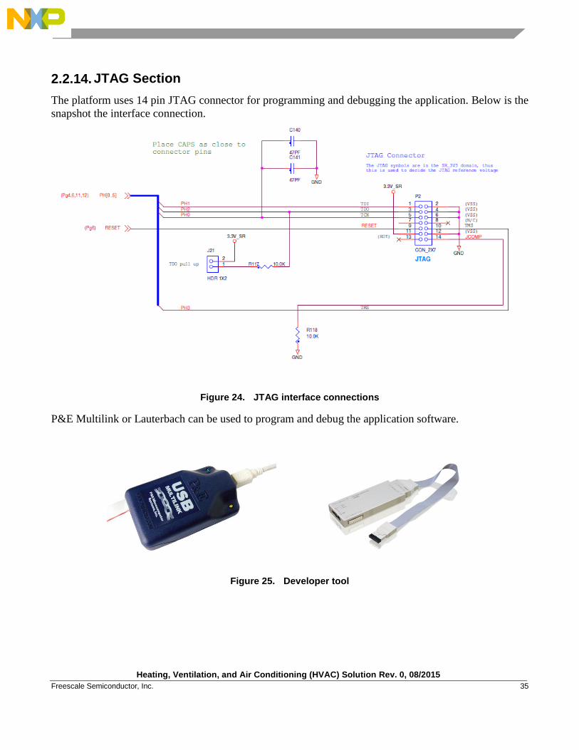
2.2.14. JTAG Section
The platform uses 14 pin JTAG connector for programming and debugging the application. Below is the
snapshot the interface connection.
Figure 24. JTAG interface connections
P&E Multilink or Lauterbach can be used to program and debug the application software.
Figure 25. Developer tool
Heating, Ventilation, and Air Conditioning (HVAC) Solution Rev. 0, 08/2015
36 Freescale Semiconductor, Inc.
Software Design
3.1. Introduction
This section describes the software design of the climate control application. Software design mainly
consists of graphics for user control, motor control tasks to take corresponding action in background,
resistive touch detection libraries, Infra red support driver and calendaring information libraries. The
software comprises of custom scheduler running on MPC5645S/MPC5606S controller. The
MPC5645S/MPC5606S controller uses 8 MHz crystal and internal PLL to generate the system clock of
124 MHz/64 MHz respectively.
The software has following main modules:
LCD TFT graphical display
User interface
o Capacitive touch pads
o IR remote control
Motor control with stall detection
o Blower Motor(s)
o Actuator Motors
Real time temperature sensing
Real time clock
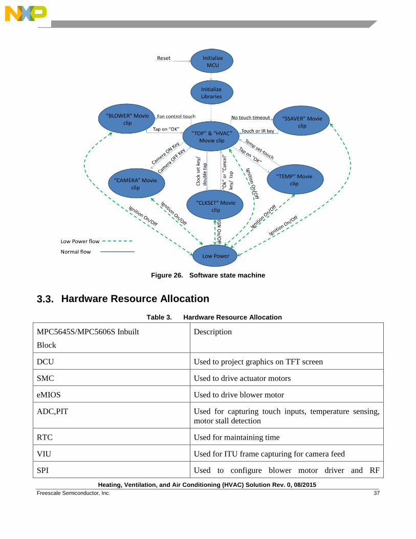
3.2. Software Architecture
Spectrum and Rainbow is power PC core based 32 bit controller so the different tasks are scheduled in
round robin manner. A scheduler is used to schedule movie clips at any particular instant of application.
Overall system state machine is shown in figure.
Heating, Ventilation, and Air Conditioning (HVAC) Solution Rev. 0, 08/2015
Freescale Semiconductor, Inc. 37
Figure 26. Software state machine
3.3. Hardware Resource Allocation
Table 3. Hardware Resource Allocation
MPC5645S/MPC5606S Inbuilt
Block
Description
DCU Used to project graphics on TFT screen
SMC Used to drive actuator motors
eMIOS Used to drive blower motor
ADC,PIT Used for capturing touch inputs, temperature sensing,
motor stall detection
RTC Used for maintaining time
VIU Used for ITU frame capturing for camera feed
SPI Used to configure blower motor driver and RF
Heating, Ventilation, and Air Conditioning (HVAC) Solution Rev. 0, 08/2015
38 Freescale Semiconductor, Inc.
MPC5645S/MPC5606S Inbuilt
Block
Description
transceiver
IIS Used for Audio playback*
IIC Used to configure Audio and Video transceiver
QSPI Used to interface QSPI non volatile memory
CAN Used for communication*
LIN Used for communication*
3.4. Graphics
3.4.1. Overview
The Graphics management module is responsible for all the graphics projected on the screen. The tasks
performed by graphics modules could be broken down as below:
Scheduling of the movie clips (mc_hvac, mc_top, mc_ssaver, mc_clkset, mc_temp, mc_blower
and mc_camera)
Movie clips manages the graphics displayed on the screen based on different application mode.
Detailed description of each movie clip is provided in section 3.4.2.
Update graphics based on user inputs either from IR remote or touch
3.4.2. Movie Clips
The complete HVAC application is divided into the movie clips as detailed below.
MC_HVAC
MC_TOP
MC_SSAVER
MC_CLKSET
MC_BLOWER
MC_TEMP
MC_CAMERA
Heating, Ventilation, and Air Conditioning (HVAC) Solution Rev. 0, 08/2015
Freescale Semiconductor, Inc. 39
3.4.2.1. MC_HVAC Movie Clip
This movie clip displays and manages the graphics for following features:
Vent control
Defogger control
Recirculation control
Profile control
Fan control
ON/OFF control
Cool/heat control
This movie clip also checks periodically if any user input either by touch or IR remote has been
detected. Upon detection the corresponding action is reflected back on screen.
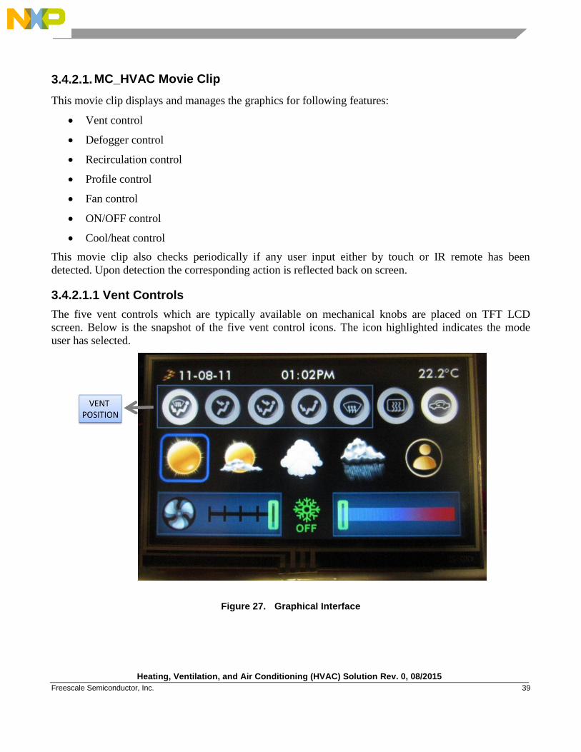
3.4.2.1.1 Vent Controls
The five vent controls which are typically available on mechanical knobs are placed on TFT LCD
screen. Below is the snapshot of the five vent control icons. The icon highlighted indicates the mode
user has selected.
Figure 27. Graphical Interface
Heating, Ventilation, and Air Conditioning (HVAC) Solution Rev. 0, 08/2015
40 Freescale Semiconductor, Inc.
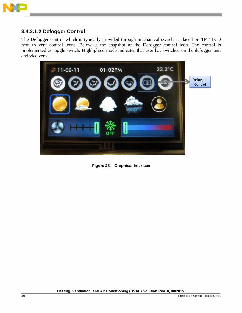
3.4.2.1.2 Defogger Control
The Defogger control which is typically provided through mechanical switch is placed on TFT LCD
next to vent control icons. Below is the snapshot of the Defogger control icon. The control is
implemented as toggle switch. Highlighted mode indicates that user has switched on the defogger unit
and vice versa.
Figure 28. Graphical Interface
Heating, Ventilation, and Air Conditioning (HVAC) Solution Rev. 0, 08/2015
Freescale Semiconductor, Inc. 41
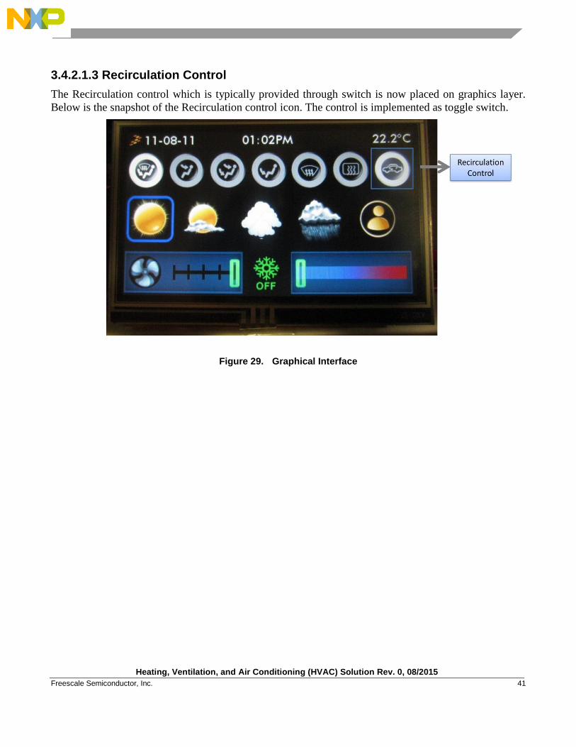
3.4.2.1.3 Recirculation Control
The Recirculation control which is typically provided through switch is now placed on graphics layer.
Below is the snapshot of the Recirculation control icon. The control is implemented as toggle switch.
Figure 29. Graphical Interface
Heating, Ventilation, and Air Conditioning (HVAC) Solution Rev. 0, 08/2015
42 Freescale Semiconductor, Inc.
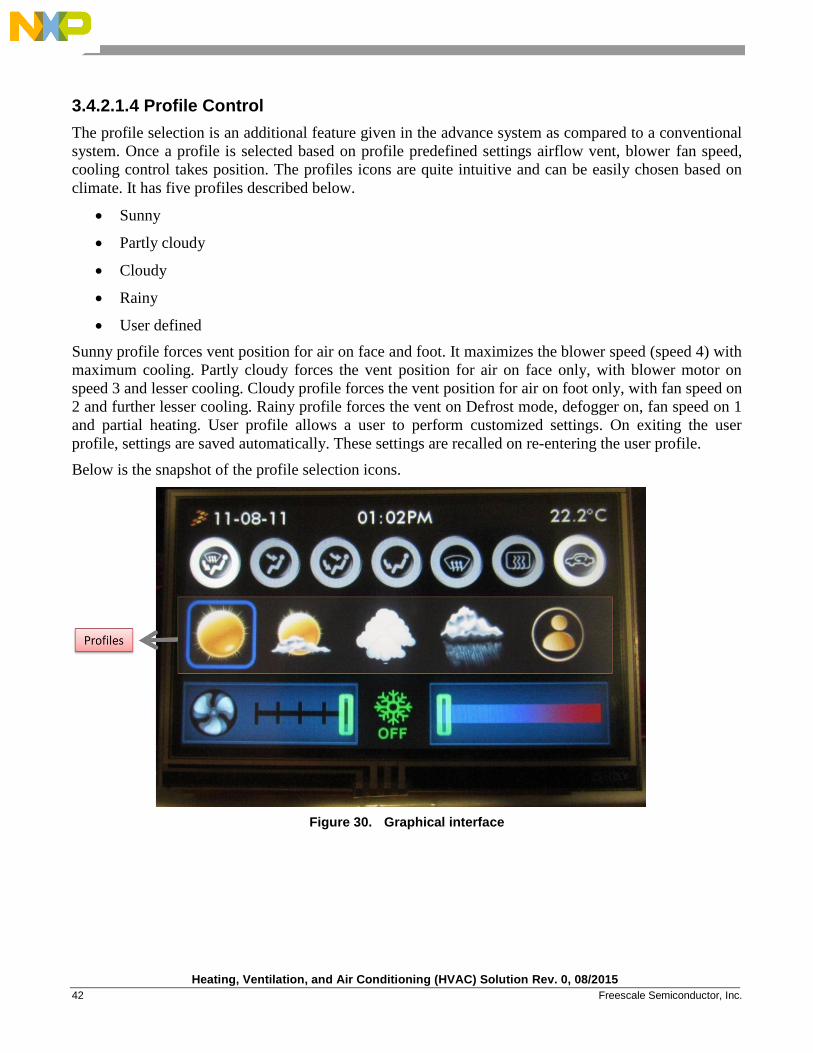
3.4.2.1.4 Profile Control
The profile selection is an additional feature given in the advance system as compared to a conventional
system. Once a profile is selected based on profile predefined settings airflow vent, blower fan speed,
cooling control takes position. The profiles icons are quite intuitive and can be easily chosen based on
climate. It has five profiles described below.
Sunny
Partly cloudy
Cloudy
Rainy
User defined
Sunny profile forces vent position for air on face and foot. It maximizes the blower speed (speed 4) with
maximum cooling. Partly cloudy forces the vent position for air on face only, with blower motor on
speed 3 and lesser cooling. Cloudy profile forces the vent position for air on foot only, with fan speed on
2 and further lesser cooling. Rainy profile forces the vent on Defrost mode, defogger on, fan speed on 1
and partial heating. User profile allows a user to perform customized settings. On exiting the user
profile, settings are saved automatically. These settings are recalled on re-entering the user profile.
Below is the snapshot of the profile selection icons.
Figure 30. Graphical interface
Heating, Ventilation, and Air Conditioning (HVAC) Solution Rev. 0, 08/2015
Freescale Semiconductor, Inc. 43
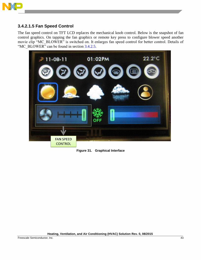
3.4.2.1.5 Fan Speed Control
The fan speed control on TFT LCD replaces the mechanical knob control. Below is the snapshot of fan
control graphics. On tapping the fan graphics or remote key press to configure blower speed another
movie clip “MC_BLOWER” is switched on. It enlarges fan speed control for better control. Details of
“MC_BLOWER” can be found in section 3.4.2.5.
Figure 31. Graphical Interface
Heating, Ventilation, and Air Conditioning (HVAC) Solution Rev. 0, 08/2015
44 Freescale Semiconductor, Inc.
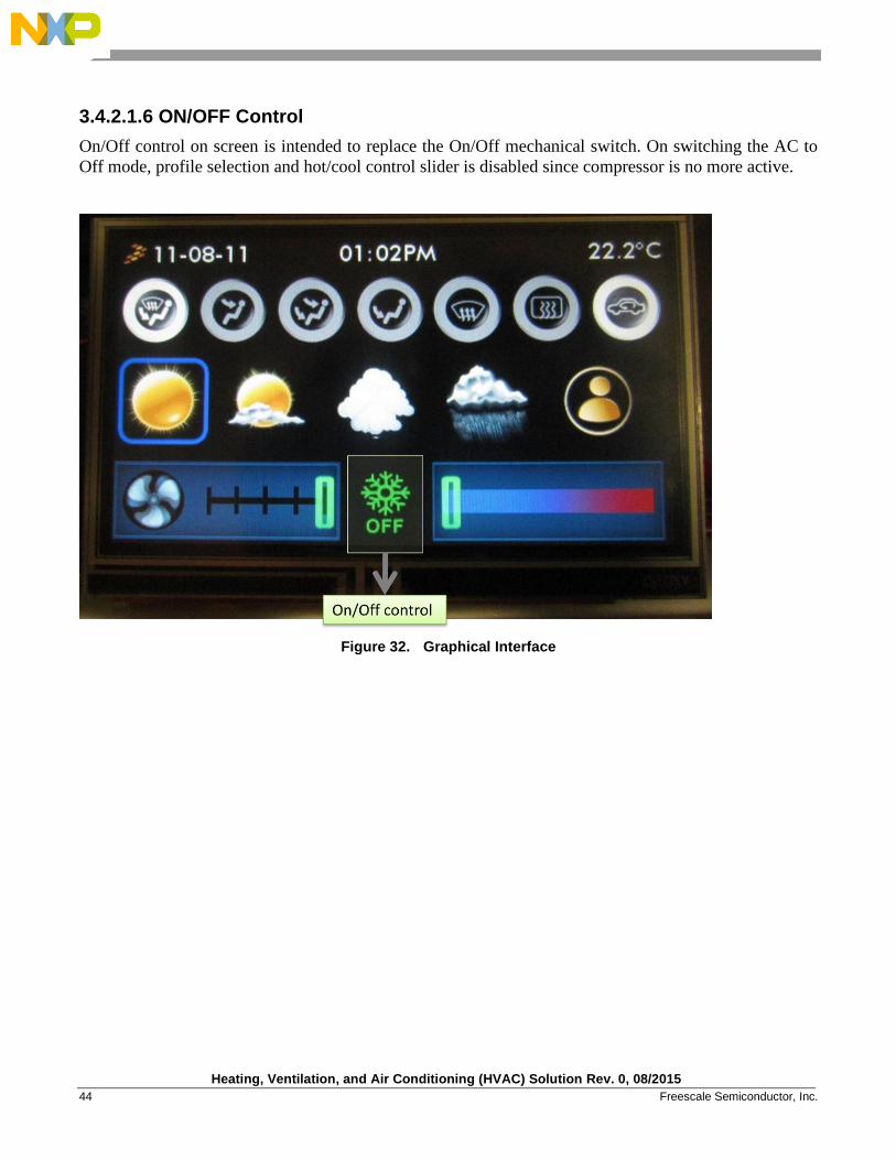
3.4.2.1.6 ON/OFF Control
On/Off control on screen is intended to replace the On/Off mechanical switch. On switching the AC to
Off mode, profile selection and hot/cool control slider is disabled since compressor is no more active.
Figure 32. Graphical Interface
Heating, Ventilation, and Air Conditioning (HVAC) Solution Rev. 0, 08/2015
Freescale Semiconductor, Inc. 45
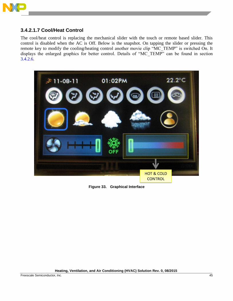
3.4.2.1.7 Cool/Heat Control
The cool/heat control is replacing the mechanical slider with the touch or remote based slider. This
control is disabled when the AC is Off. Below is the snapshot. On tapping the slider or pressing the
remote key to modify the cooling/heating control another movie clip “MC_TEMP” is switched On. It
displays the enlarged graphics for better control. Details of “MC_TEMP” can be found in section
3.4.2.6.
Figure 33. Graphical Interface
Heating, Ventilation, and Air Conditioning (HVAC) Solution Rev. 0, 08/2015
46 Freescale Semiconductor, Inc.
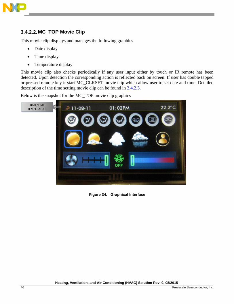
3.4.2.2. MC_TOP Movie Clip
This movie clip displays and manages the following graphics
Date display
Time display
Temperature display
This movie clip also checks periodically if any user input either by touch or IR remote has been
detected. Upon detection the corresponding action is reflected back on screen. If user has double tapped
or pressed remote key it start MC_CLKSET movie clip which allow user to set date and time. Detailed
description of the time setting movie clip can be found in 3.4.2.3.
Below is the snapshot for the MC_TOP movie clip graphics
Figure 34. Graphical Interface
Heating, Ventilation, and Air Conditioning (HVAC) Solution Rev. 0, 08/2015
Freescale Semiconductor, Inc. 47
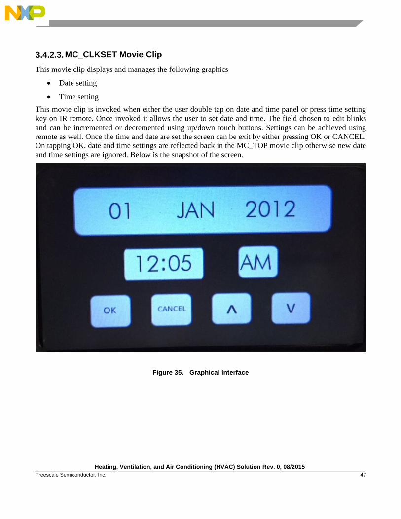
3.4.2.3. MC_CLKSET Movie Clip
This movie clip displays and manages the following graphics
Date setting
Time setting
This movie clip is invoked when either the user double tap on date and time panel or press time setting
key on IR remote. Once invoked it allows the user to set date and time. The field chosen to edit blinks
and can be incremented or decremented using up/down touch buttons. Settings can be achieved using
remote as well. Once the time and date are set the screen can be exit by either pressing OK or CANCEL.
On tapping OK, date and time settings are reflected back in the MC_TOP movie clip otherwise new date
and time settings are ignored. Below is the snapshot of the screen.
Figure 35. Graphical Interface

Heating, Ventilation, and Air Conditioning (HVAC) Solution Rev. 0, 08/2015
48 Freescale Semiconductor, Inc.
3.4.2.4. MC_SSAVER Movie Clip
This screen saver movie clip displays and manages the graphics for following items
Date Display
This movie clip is invoked when the screen is untouched for two minutes. It displays the clock in 100
pixel font size. On tapping the screen or remote key, screen saver screen vanishes and MC_HVAC and
MC_TOP movie clip starts back. The screen saver clip is not scheduled when time setting is in progress.
Below is the snapshot of the screen.
Figure 36. Graphical Interface
Heating, Ventilation, and Air Conditioning (HVAC) Solution Rev. 0, 08/2015
Freescale Semiconductor, Inc. 49
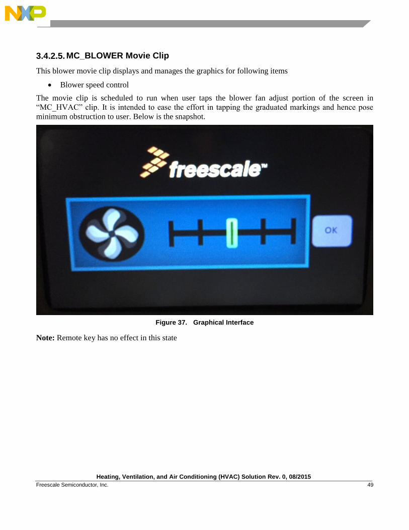
3.4.2.5. MC_BLOWER Movie Clip
This blower movie clip displays and manages the graphics for following items
Blower speed control
The movie clip is scheduled to run when user taps the blower fan adjust portion of the screen in
“MC_HVAC” clip. It is intended to ease the effort in tapping the graduated markings and hence pose
minimum obstruction to user. Below is the snapshot.
Figure 37. Graphical Interface
Note: Remote key has no effect in this state
Heating, Ventilation, and Air Conditioning (HVAC) Solution Rev. 0, 08/2015
50 Freescale Semiconductor, Inc.
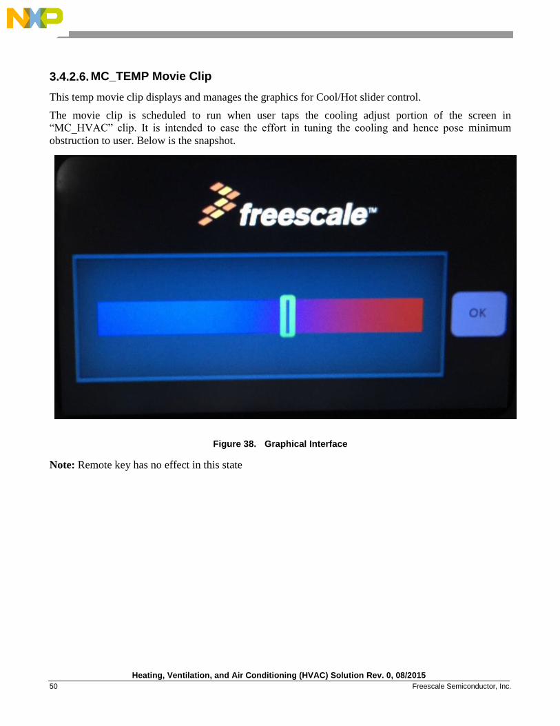
3.4.2.6. MC_TEMP Movie Clip
This temp movie clip displays and manages the graphics for Cool/Hot slider control.
The movie clip is scheduled to run when user taps the cooling adjust portion of the screen in
“MC_HVAC” clip. It is intended to ease the effort in tuning the cooling and hence pose minimum
obstruction to user. Below is the snapshot.
Figure 38. Graphical Interface
Note: Remote key has no effect in this state
Heating, Ventilation, and Air Conditioning (HVAC) Solution Rev. 0, 08/2015
Freescale Semiconductor, Inc. 51
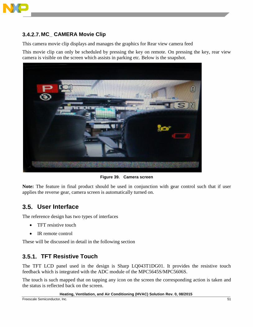
3.4.2.7. MC_ CAMERA Movie Clip
This camera movie clip displays and manages the graphics for Rear view camera feed
This movie clip can only be scheduled by pressing the key on remote. On pressing the key, rear view
camera is visible on the screen which assists in parking etc. Below is the snapshot.
Figure 39. Camera screen
Note: The feature in final product should be used in conjunction with gear control such that if user
applies the reverse gear, camera screen is automatically turned on.
3.5. User Interface
The reference design has two types of interfaces
TFT resistive touch
IR remote control
These will be discussed in detail in the following section
3.5.1. TFT Resistive Touch
The TFT LCD panel used in the design is Sharp LQ043T1DG01. It provides the resistive touch
feedback which is integrated with the ADC module of the MPC5645S/MPC5606S.
The touch is such mapped that on tapping any icon on the screen the corresponding action is taken and
the status is reflected back on the screen.
Heating, Ventilation, and Air Conditioning (HVAC) Solution Rev. 0, 08/2015
52 Freescale Semiconductor, Inc.
3.5.2. Infra Red remote control
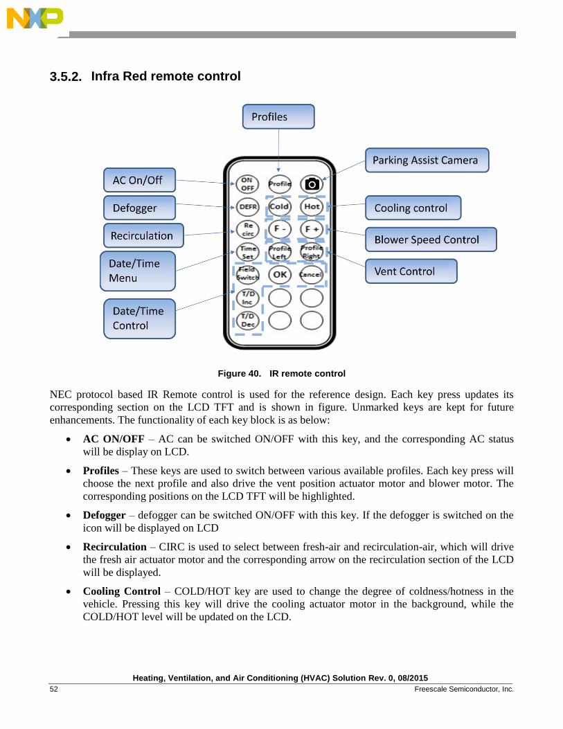
Figure 40. IR remote control
NEC protocol based IR Remote control is used for the reference design. Each key press updates its
corresponding section on the LCD TFT and is shown in figure. Unmarked keys are kept for future
enhancements. The functionality of each key block is as below:
AC ON/OFF – AC can be switched ON/OFF with this key, and the corresponding AC status
will be display on LCD.
Profiles – These keys are used to switch between various available profiles. Each key press will
choose the next profile and also drive the vent position actuator motor and blower motor. The
corresponding positions on the LCD TFT will be highlighted.
Defogger – defogger can be switched ON/OFF with this key. If the defogger is switched on the
icon will be displayed on LCD
Recirculation – CIRC is used to select between fresh-air and recirculation-air, which will drive
the fresh air actuator motor and the corresponding arrow on the recirculation section of the LCD
will be displayed.
Cooling Control – COLD/HOT key are used to change the degree of coldness/hotness in the
vehicle. Pressing this key will drive the cooling actuator motor in the background, while the
COLD/HOT level will be updated on the LCD.
Heating, Ventilation, and Air Conditioning (HVAC) Solution Rev. 0, 08/2015
Freescale Semiconductor, Inc. 53
Blower Speed Control – F+/- keys are used to update the blower speed by increasing the duty
cycle of the PWM used to drive the PMDC blower motor. This will also update the blower speed
on the LCD.
Vent Control – These keys are used to change the vent positions. This will perform the
background action and also update the screen.
Date/Time menu – Date/Time Menu is GUI is invoked using the time set key. Further date/time
setting is done using the date/time control keys.
Parking assist camera – This key is to switch On the camera view.
3.6. Motor Drive
This HVAC application consist of following motors:
Blower Motor
Fresh Air inlet control motor
Vent Position control motor
Cooling control motor
3.6.1. Blower Motor
Blower motor is controlled in the HVAC unit using eMIOS through driver IC MC33984. Blower motor
is given 5 stage control based on console. Depending upon the input received from console the duty
cycle of the PWM signal is changed to vary the speed of blower. Blower motor stall detection feature is
also provided. If the motor jams due to any mechanical or electrical reason the motor drive is stopped
which prevents the motor coil from burning.
3.6.2. Fresh Air Inlet Vent Control Motor
This motor is used to control the air circulation inside the cabin. Depending on its position air is allowed
into the cabin either from outside or internal air is re-circulated. The motor is driven using stepper motor
module. Based on inputs received from the console the appropriate action is taken in the SMC to adjust
the flap position.
3.6.3. Air Vent Position Control Motor
This motor is used to adjust the flap to control the direction of air flow in the cabin. This motor is driven
using the stepper motor module. Based on inputs received from the console the appropriate action is
taken in the SMC to adjust the flap positions.
Heating, Ventilation, and Air Conditioning (HVAC) Solution Rev. 0, 08/2015
54 Freescale Semiconductor, Inc.
3.6.4. Hot /Cool Control Motor
This motor is used to adjust the flap to control the mixing of hot and cool air. This motor is driven using
the stepper motor module. Based on inputs received from the console the appropriate action is taken in
the SMC to adjust the flap positions.
3.7. Date and Real Time Clock
This real time clock is available at the top right corner of the screen. It provides below mentioned
features
AM/PM format
24 hours format
Resettable
Calendaring information
The applications maintain the date and time along with calendaring information. The clock continues to
run in low power mode so that time is maintained even when ignition is off.
3.8. Infra Red Control
IR allows the user to configure different HVAC settings remotely. The IR sensor is interfaced to an
eMIOS channel. On a key press, based on the pattern received, key is decoded and the application layer
is informed. The graphics layer represents the action on screen along with passing appropriate command
to motor control modules.
3.9. Temperature Sensor
The application takes the feed from a temperature sensor which monitors the cabin temperature. It is
interfaced to analog channel and the MC_TOP movie clips reads the channels and displays the
temperature. For automated climate control system there can be multiple of such sensors placed in
different positions in cabin which monitors the temperature and provide feedback to maintain the
uniform temperature throughout the cabin.
Heating, Ventilation, and Air Conditioning (HVAC) Solution Rev. 0, 08/2015
Freescale Semiconductor, Inc. 55
Testing and Measurements
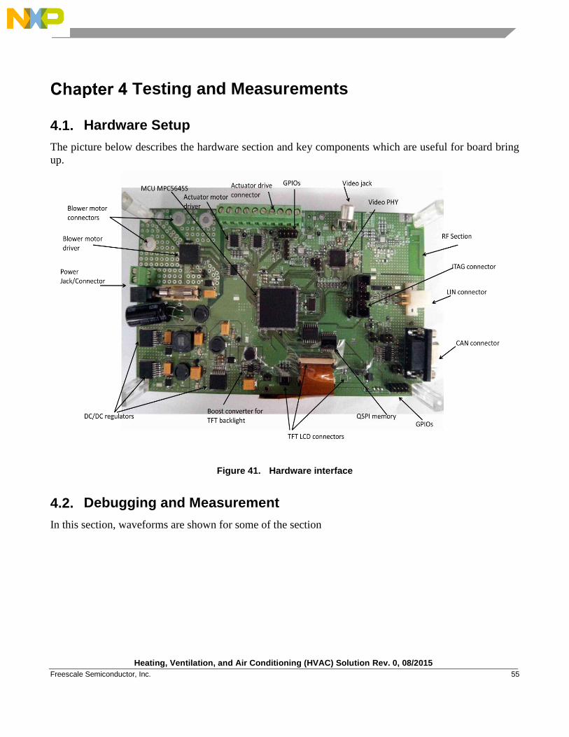
4.1. Hardware Setup
The picture below describes the hardware section and key components which are useful for board bring
up.
Figure 41. Hardware interface
4.2. Debugging and Measurement
In this section, waveforms are shown for some of the section
Heating, Ventilation, and Air Conditioning (HVAC) Solution Rev. 0, 08/2015
56 Freescale Semiconductor, Inc.
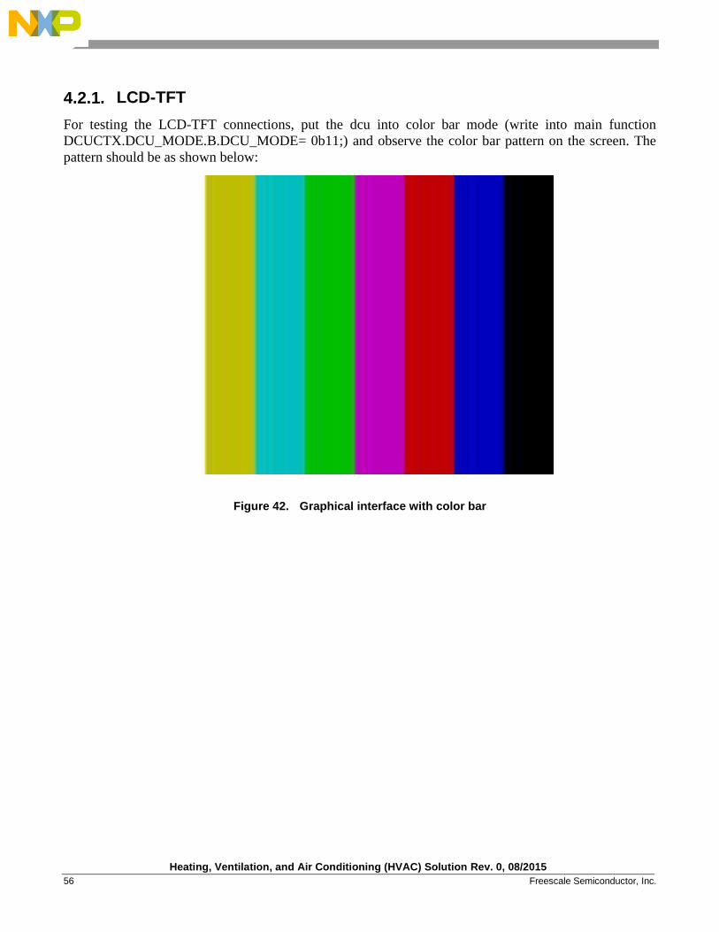
4.2.1. LCD-TFT
For testing the LCD-TFT connections, put the dcu into color bar mode (write into main function
DCUCTX.DCU_MODE.B.DCU_MODE= 0b11;) and observe the color bar pattern on the screen. The
pattern should be as shown below:
Figure 42. Graphical interface with color bar
Heating, Ventilation, and Air Conditioning (HVAC) Solution Rev. 0, 08/2015
Freescale Semiconductor, Inc. 57
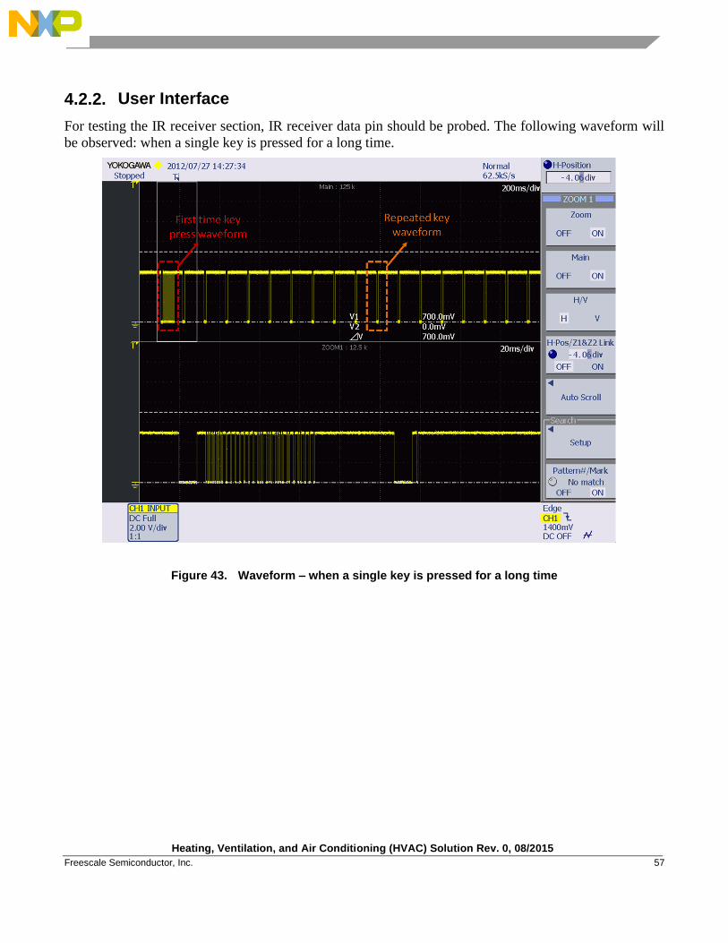
4.2.2. User Interface
For testing the IR receiver section, IR receiver data pin should be probed. The following waveform will
be observed: when a single key is pressed for a long time.
Figure 43. Waveform – when a single key is pressed for a long time
Heating, Ventilation, and Air Conditioning (HVAC) Solution Rev. 0, 08/2015
58 Freescale Semiconductor, Inc.
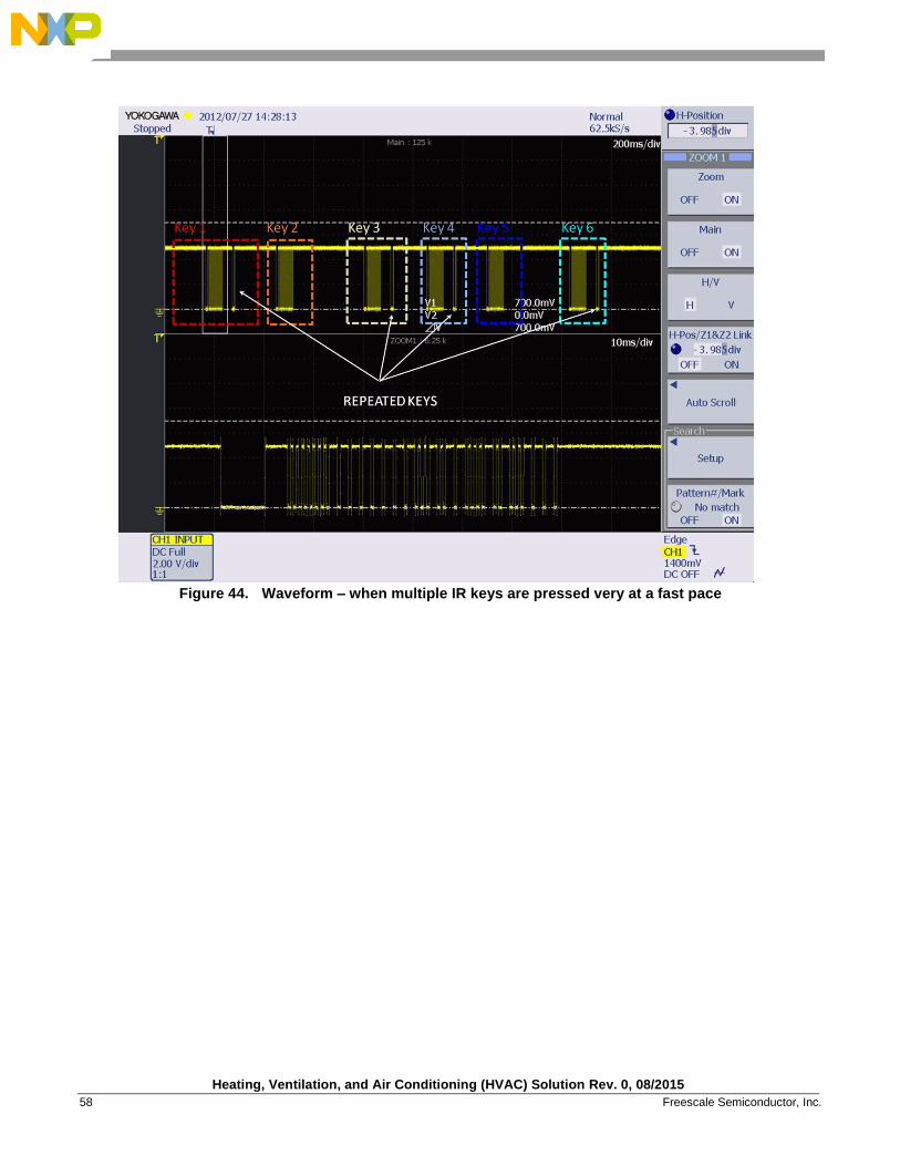
Figure 44. Waveform – when multiple IR keys are pressed very at a fast pace
Heating, Ventilation, and Air Conditioning (HVAC) Solution Rev. 0, 08/2015
Freescale Semiconductor, Inc. 59
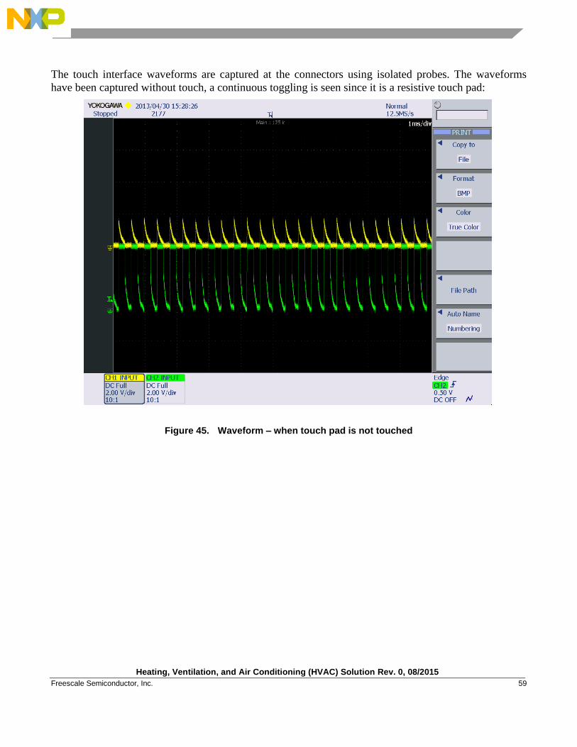
The touch interface waveforms are captured at the connectors using isolated probes. The waveforms
have been captured without touch, a continuous toggling is seen since it is a resistive touch pad:
Figure 45. Waveform – when touch pad is not touched

Heating, Ventilation, and Air Conditioning (HVAC) Solution Rev. 0, 08/2015
60 Freescale Semiconductor, Inc.
4.2.3. Motor control
Waveforms for each of the interfaces are shown in following sections.
4.2.3.1. Blower Motor
Waveform for blower motor control at different levels (changed using the user interface) is probed at the
MC33984 HS0 pin and is shown in figure below:
Figure 46. Waveform – Blower motor control at different speed levels
Heating, Ventilation, and Air Conditioning (HVAC) Solution Rev. 0, 08/2015
Freescale Semiconductor, Inc. 61
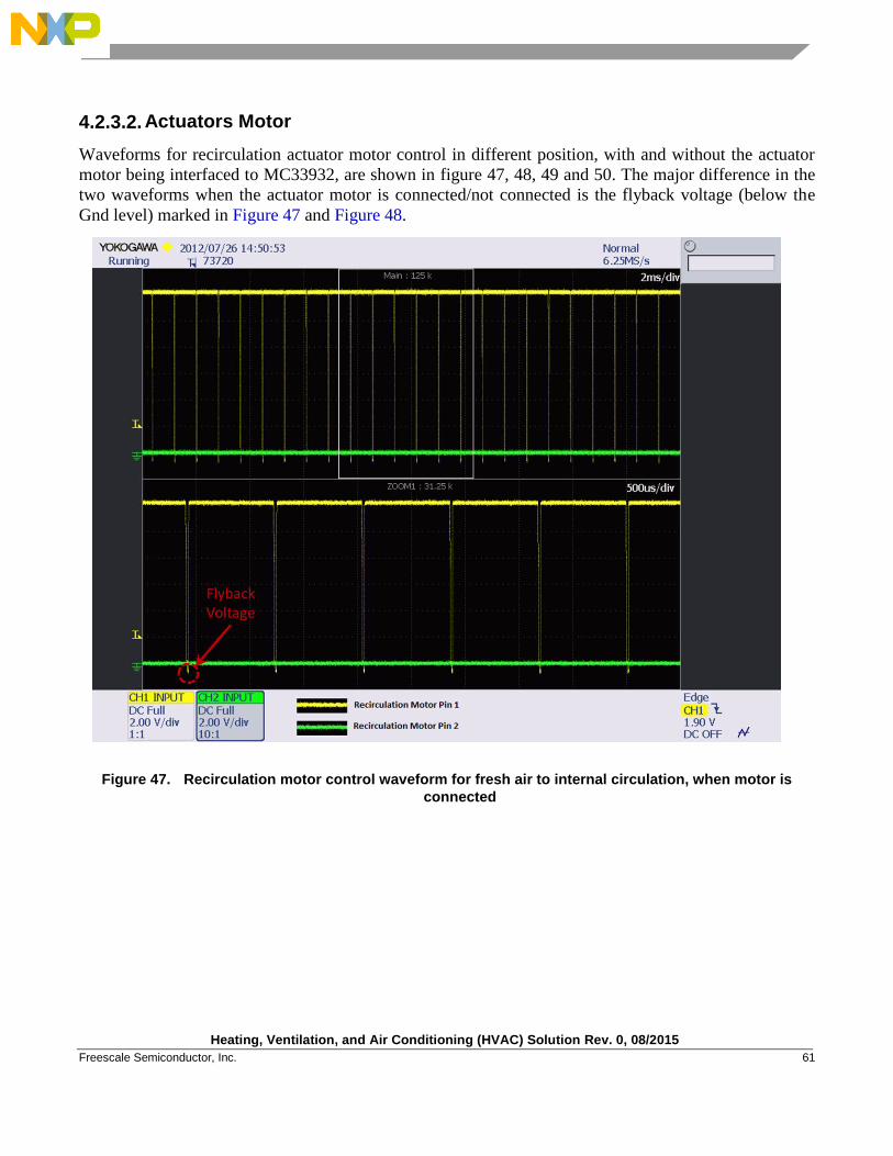
4.2.3.2. Actuators Motor
Waveforms for recirculation actuator motor control in different position, with and without the actuator
motor being interfaced to MC33932, are shown in figure 47, 48, 49 and 50. The major difference in the
two waveforms when the actuator motor is connected/not connected is the flyback voltage (below the
Gnd level) marked in Figure 47 and Figure 48.
Figure 47. Recirculation motor control waveform for fresh air to internal circulation, when motor is
connected
Heating, Ventilation, and Air Conditioning (HVAC) Solution Rev. 0, 08/2015
62 Freescale Semiconductor, Inc.
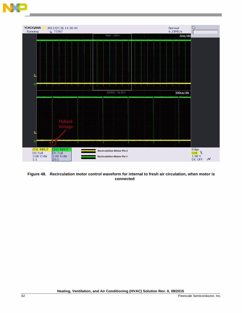
Figure 48. Recirculation motor control waveform for internal to fresh air circulation, when motor is
connected
Heating, Ventilation, and Air Conditioning (HVAC) Solution Rev. 0, 08/2015
Freescale Semiconductor, Inc. 63
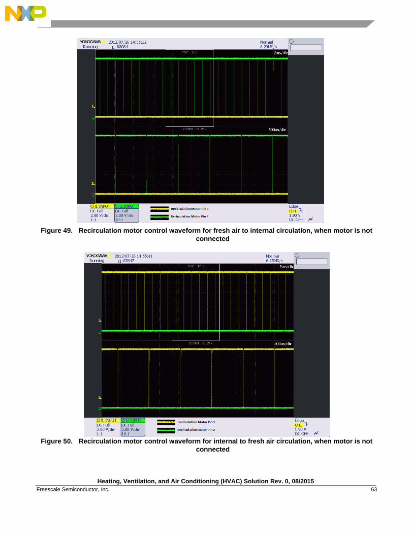
Figure 49. Recirculation motor control waveform for fresh air to internal circulation, when motor is not
connected
Figure 50. Recirculation motor control waveform for internal to fresh air circulation, when motor is not
connected
Heating, Ventilation, and Air Conditioning (HVAC) Solution Rev. 0, 08/2015
64 Freescale Semiconductor, Inc.
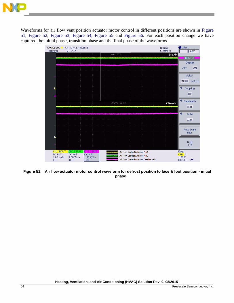
Waveforms for air flow vent position actuator motor control in different positions are shown in Figure
51, Figure 52, Figure 53, Figure 54, Figure 55 and Figure 56. For each position change we have
captured the initial phase, transition phase and the final phase of the waveforms.
Figure 51. Air flow actuator motor control waveform for defrost position to face & foot position - initial
phase
Heating, Ventilation, and Air Conditioning (HVAC) Solution Rev. 0, 08/2015
Freescale Semiconductor, Inc. 65
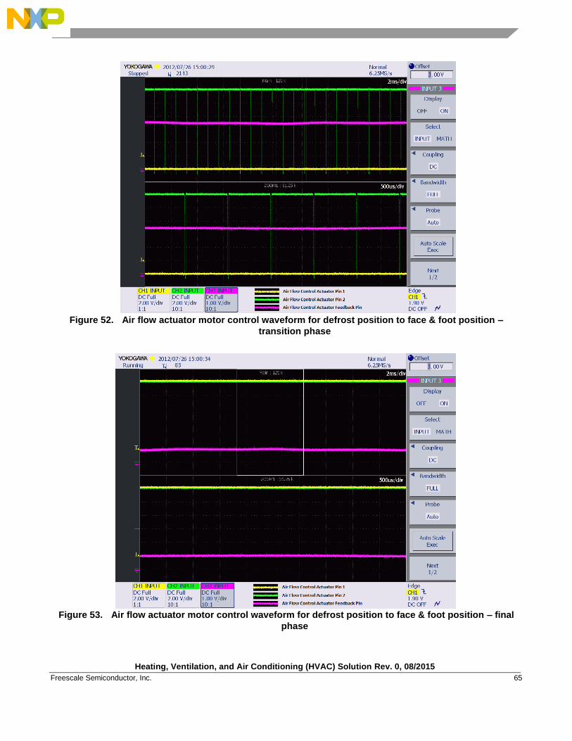
Figure 52. Air flow actuator motor control waveform for defrost position to face & foot position –
transition phase
Figure 53. Air flow actuator motor control waveform for defrost position to face & foot position – final
phase
Heating, Ventilation, and Air Conditioning (HVAC) Solution Rev. 0, 08/2015
66 Freescale Semiconductor, Inc.
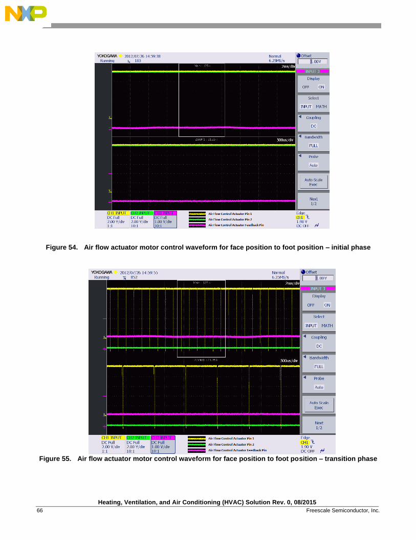
Figure 54. Air flow actuator motor control waveform for face position to foot position – initial phase
Figure 55. Air flow actuator motor control waveform for face position to foot position – transition phase
Heating, Ventilation, and Air Conditioning (HVAC) Solution Rev. 0, 08/2015
Freescale Semiconductor, Inc. 67
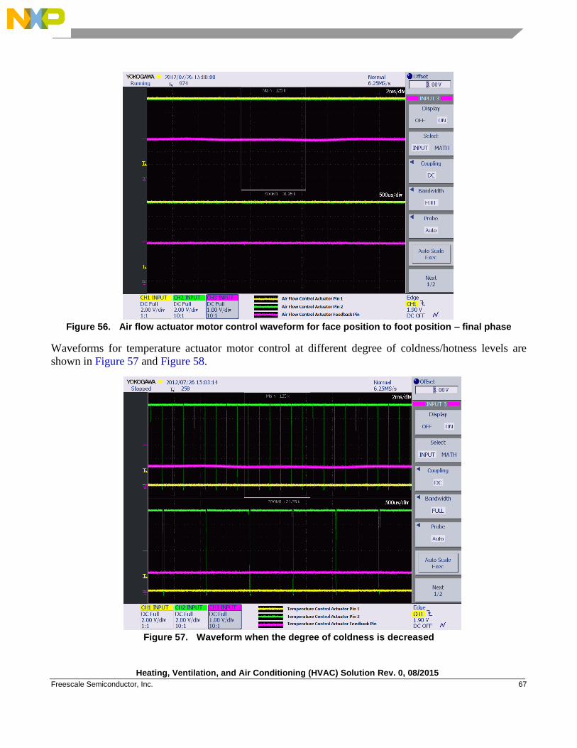
Figure 56. Air flow actuator motor control waveform for face position to foot position – final phase
Waveforms for temperature actuator motor control at different degree of coldness/hotness levels are
shown in Figure 57 and Figure 58.
Figure 57. Waveform when the degree of coldness is decreased
Heating, Ventilation, and Air Conditioning (HVAC) Solution Rev. 0, 08/2015
68 Freescale Semiconductor, Inc.
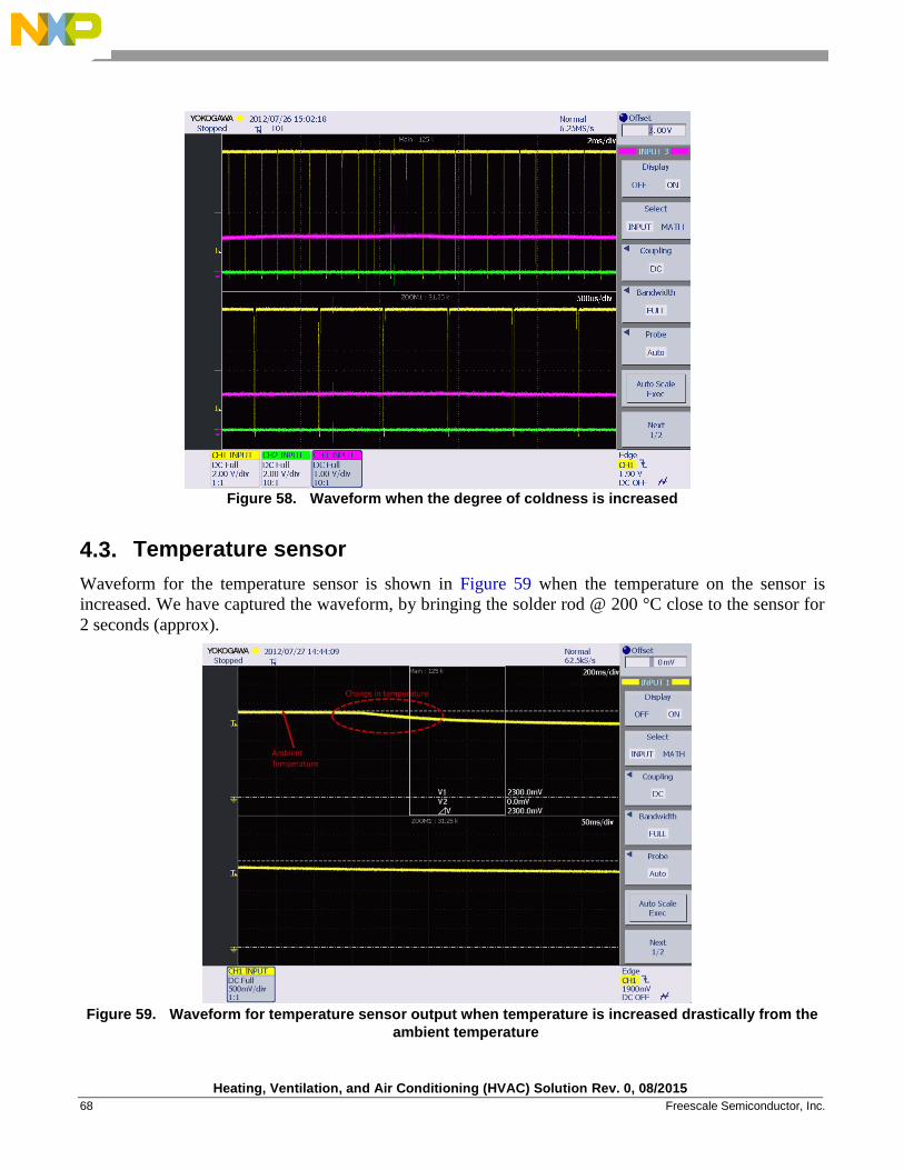
Figure 58. Waveform when the degree of coldness is increased
4.3. Temperature sensor
Waveform for the temperature sensor is shown in Figure 59 when the temperature on the sensor is
increased. We have captured the waveform, by bringing the solder rod @ 200 °C close to the sensor for
2 seconds (approx).
Figure 59. Waveform for temperature sensor output when temperature is increased drastically from the
ambient temperature

Heating, Ventilation, and Air Conditioning (HVAC) Solution Rev. 0, 08/2015
Freescale Semiconductor, Inc. 69
APPENDIX A Schematic and Layout
A.1 Schematic
5
5
4
4
3
3
2
2
1
1
D D
C C
B B
A A
Table of Contents
Power supply2 Notes3
RevisionsRev Description
X1
Date
456789101112
MCU DecouplingMPC5645S PeripheralsTFT DisplaysMemoryMotorsCAN AND LIN InterfaceAudio and Video InputDebug
08/05/2011
X2 10/04/2011Addition of motor DriversChange in TFT connector
Addition of RFinterface
X3Rev 2.0- Low PWR Implementation, Ignition ckt, and MC33932 added.
25/02/2013
Drawing Title:
Size Document Number Rev
Date: Sheet of
Page Title:
A
Microcontroller Solutions Group
l ii
f i ii
I fication: F P: FI O:
SCH-xxxxx PDF: SPF-xxxxx X3
MPC5645S_HVAC_2.0
C
Tuesday, March 26, 2013
TITLE PAGE
t
t
1 12
____X____Drawing Title:
Size Document Number Rev
Date: Sheet of
Page Title:
A
Microcontroller Solutions Group
l ii
f i ii
I fication: F P: FI O:
SCH-xxxxx PDF: SPF-xxxxx X3
MPC5645S_HVAC_2.0
C
Tuesday, March 26, 2013
TITLE PAGE
t
t
1 12
____X____Drawing Title:
Size Document Number Rev
Date: Sheet of
Page Title:
A
Microcontroller Solutions Group
l ii
f i ii
I fication: F P: FI O:
SCH-xxxxx PDF: SPF-xxxxx X3
MPC5645S_HVAC_2.0
C
Tuesday, March 26, 2013
TITLE PAGE
t
t
1 12
____X____

5
5
4
4
3
3
2
2
1
1
D D
C C
B B
A A
1. Unless Otherwise Specified:
All resistors are in ohms, 5%, 1/8 Watt
All capacitors are in uF, 20%, 50V
All voltages are DC
All polarized capacitors are aluminum or Tentalum cap
Drawing Title:
Size Document Number Rev
Date: Sheet of
Page Title:
sification: P: O:
SCH-xxxxx PDF: SPF-xxxxx X3
MPC5645S_HVAC_2.0
C
Tuesday, March 26, 2013
NOTES
2 12
___ XDrawing Title:
Size Document Number Rev
Date: Sheet of
Page Title:
sification: P: O:
SCH-xxxxx PDF: SPF-xxxxx X3
MPC5645S_HVAC_2.0
C
Tuesday, March 26, 2013
NOTES
2 12
___ XDrawing Title:
Size Document Number Rev
Date: Sheet of
Page Title:
sification: P: O:
SCH-xxxxx PDF: SPF-xxxxx X3
MPC5645S_HVAC_2.0
C
Tuesday, March 26, 2013
NOTES
2 12
___ X
5
5
4
4
3
3
2
2
1
1
D D
C C
B B
A A
Main Power-In
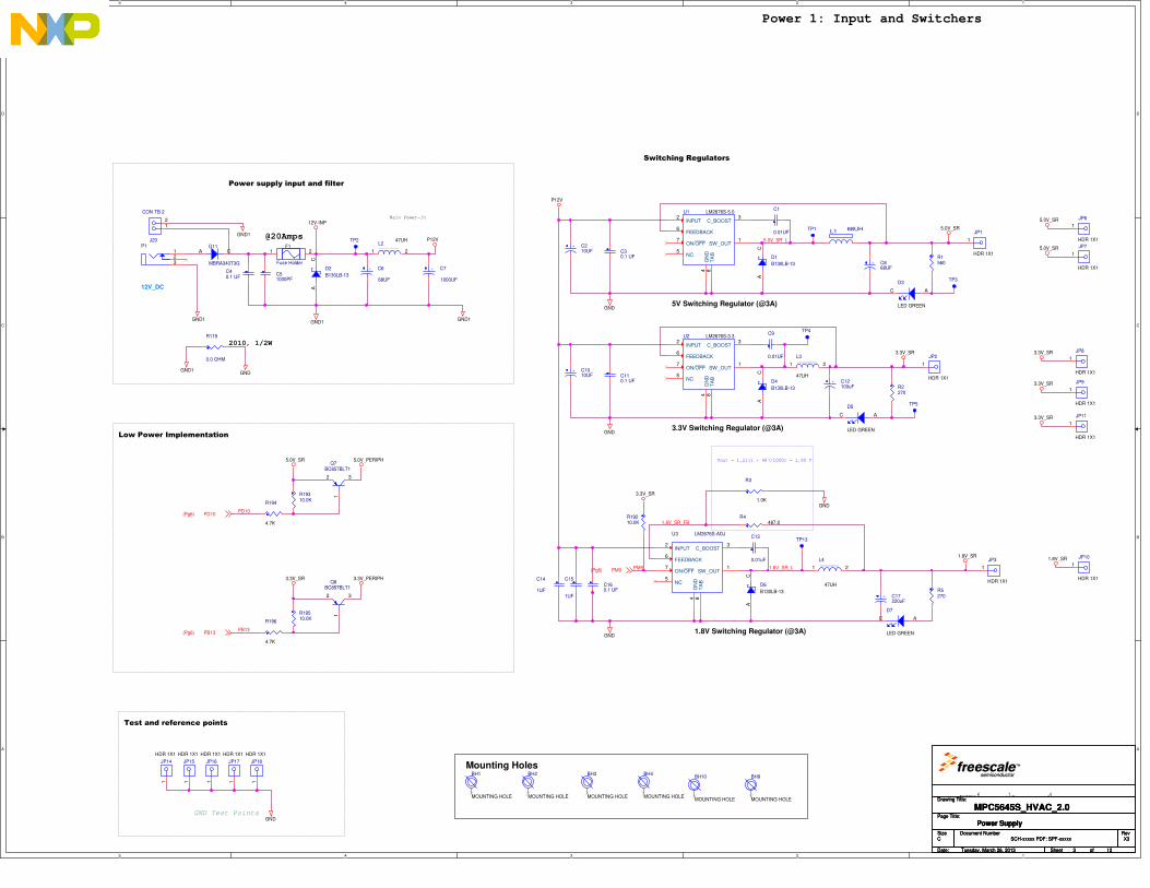
Switching Regulators
3.3V Switching Regulator (@3A)
5V Switching Regulator (@3A)
Power supply input and filter
Power 1: Input and Switchers
GND Test Points
Test and reference points
1.8V Switching Regulator (@3A)
Vout = 1.21(1 + 487/1000) = 1.80 V
Mounting Holes
Low Power Implementation
@20Amps
2010, 1/2W
5.0V_SR_L
1.8V_SR_FB
1.8V_SR_LPM9
PD10
PB13
P12V
5.0V_SR
GND
GND1
3.3V_SR
GND
P12V
GND1
GND
GND
1.8V_SR
GND
GND1GND
GND1
12V-INP
GND1
1.8V_SR
3.3V_SR
3.3V_SR
5.0V_SR
5.0V_SR
3.3V_SR
3.3V_SR
5.0V_PERIPH5.0V_SR
3.3V_PERIPH3.3V_SR
PM9(Pg6)
PD10(Pg6)
PB13(Pg6)
Drawing Title:
Size Document Number Rev
Date: Sheet of
Page Title:
sification: P: O:
SCH-xxxxx PDF: SPF-xxxxx X3
MPC5645S_HVAC_2.0
C
Tuesday, March 26, 2013
Power Supply
3 12
_
Drawing Title:
Size Document Number Rev
Date: Sheet of
Page Title:
sification: P: O:
SCH-xxxxx PDF: SPF-xxxxx X3
MPC5645S_HVAC_2.0
C
Tuesday, March 26, 2013
Power Supply
3 12
_
Drawing Title:
Size Document Number Rev
Date: Sheet of
Page Title:
sification: P: O:
SCH-xxxxx PDF: SPF-xxxxx X3
MPC5645S_HVAC_2.0
C
Tuesday, March 26, 2013
Power Supply
3 12
_
R194
4.7K
JP17
HDR 1X1
1
C110.1 UF
+ C6
68UF
D2
B130LB-13
AC
JP11
HDR 1X1
1
C1
0.01UF
BH3
MOUNTING HOLE
TP5
R19210.0K
BH4
MOUNTING HOLE
C9
0.01UF
R19510.0K
F1
Fuse Holder
1 2
JP3
HDR 1X1
1
L3
47UH
1 2
C51000PF
D5
LED GREEN
AC
TP13
U2 LM2676S-3.3
INPUT2
SW_OUT1
C_BOOST3
GN
D4
TA
B8
FEEDBACK6
ON/OFF7
NC5
Q7BC857BLT1
1
2 3
C13
0.01uF
TP1
D3
LED GREEN
AC
D7
LED GREEN
ACR196
4.7K
JP2
HDR 1X1
1
L1 68UH
D4
B130LB-13
AC
R5270
R19310.0K
R3
1.0K
+ C210UF
C160.1 UF
BH9
MOUNTING HOLE
J20
CON TB 2
12
+ C12100uF
R1560
U1 LM2676S-5.0
INPUT2
SW_OUT1
C_BOOST3
GN
D4
TA
B8
FEEDBACK6
ON/OFF7
NC5
BH10
MOUNTING HOLE
R119
0.0 OHM
JP6
HDR 1X1
1
L4
47UH
1 2
D11
MBRA340T3G
A C
TP4
L247UH
1 2
R2270
R4487.0
+ C1010UF
JP7
HDR 1X1
1
D6
B130LB-13
AC
D1
B130LB-13
AC
+ C17220uF
JP8
HDR 1X1
1
JP18
HDR 1X1
1
+ C7
1000UF
JP15
HDR 1X1
1
JP9
HDR 1X1
1
JP14
HDR 1X1
1
BH1
MOUNTING HOLE
C14
1UF
C40.1 UF
JP16
HDR 1X1
1
JP10
HDR 1X1
1
JP1
HDR 1X1
1
C30.1 UF
BH2
MOUNTING HOLE
TP2
U3 LM2676S-ADJ
INPUT2
SW_OUT1
C_BOOST3
GN
D4
TA
B8
FEEDBACK6
ON/OFF7
NC5
P1
12V_DC
123 + C8
68UF
C15
1UF
Q8BC857BLT1
1
2 3
TP3
5
5
4
4
3
3
2
2
1
1
D D
C C
B B
A A
DSPI_CS0_0
ATTN _
IRQ_b_
RST_
2010, 1/2W
DSPI_SIN_0
DSPI_SOUT_0
DSPI_SCK_0
PH4
PD15
PD14
PB11
PD12
PH4
PD15
PB7
PB8
PB9
PB11
PD12
PD14
RFGND
RFGND
RFGND
RFGND
RFGND
RFGND
RFGND
RFGND
RFGND
GND
3.3V_PERIPH
3.3V_PERIPH
PB7(Pg4,6)
PB9(Pg4,6)PB8(Pg4,6)
PH[0..5](Pg6,11,12)
PD[0..15](Pg3,6,9,11,12)
PB7(Pg4,6)
PB8(Pg4,6)
PB9(Pg4,6)
PB11(Pg6)
Drawing Title:
Size Document Number Rev
Date: Sheet of
Page Title:
i
SCH-xxxxx PDF: SPF-xxxxx X3
MPC5645S_HVAC_2.0
C
Tuesday, March 26, 2013
i
4 12
Drawing Title:
Size Document Number Rev
Date: Sheet of
Page Title:
i
SCH-xxxxx PDF: SPF-xxxxx X3
MPC5645S_HVAC_2.0
C
Tuesday, March 26, 2013
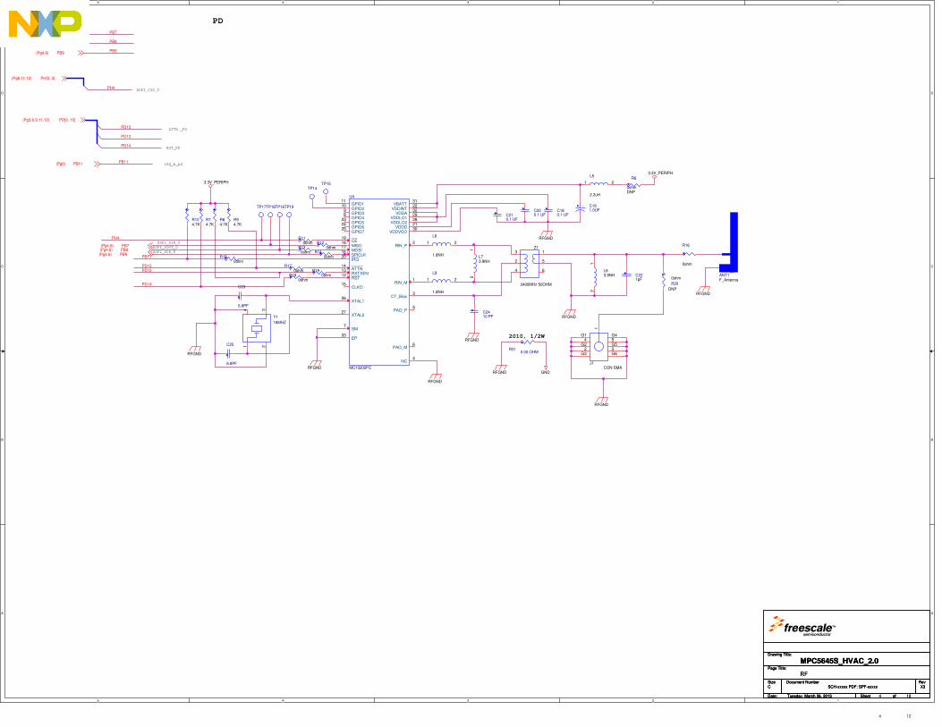
RF
4 12
Drawing Title:
Size Document Number Rev
Date: Sheet of
Page Title:
i
SCH-xxxxx PDF: SPF-xxxxx X3
MPC5645S_HVAC_2.0
C
Tuesday, March 26, 2013
4 12
+ C191.0UF
R190ohm
J1CON SMA
1
2
4
3
5G1
G2
G3
G4
G5
G6
C23
6.8PF
Y1
16MHZ
14 3
2
L6
1.8NH
1 2
U4
MC13202FC
ATTN14
CE19
CLKO15
GPIO111
GPIO210
GPIO39
GPIO48
GPIO725
GPIO523
GPIO624
IRQ20
MISO18
MOSI17
PAO_M6
PAO_P5
RIN_M1
RIN_P2
RST12 RXTXEN13
SM7
SPICLK16
NC4
CT_Bias3
XTAL126
XTAL227
VBATT31
VDDA32
VDDD21
VDDINT22
VDDLO129
VDDLO228
VDDVCO30
EP33
C210.1 UF
C25
6.8PF
R150ohm
L73.9NH
12
R104.7K
R180ohm
L5
2.2uH
1 2
R16
0ohm
R110ohm
C221pF
R20
0ohm
DNP
R84.7K
R210.00 OHM
R74.7K
Z1
2400MHz 50OHM
5
1
6
2
3
4L9
1.8NH
1 2
TP15TP14
R120ohm
TP17C180.1 UF
R6
0ohmDNP
TP18
R94.7K
R130ohm
TP16
ANT1F_Antenna
TP19
R140ohm
C2410 PF
C200.1 UF
L83.9NH
12
R170ohm
5
5
4
4
3
3
2
2
1
1
D D
C C
B B
A A
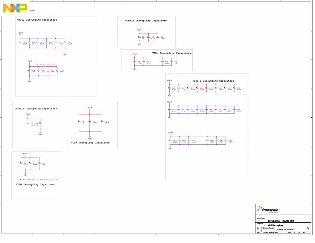
Decoupling Caps
VDD12 Decoupling Capacitors
VDDPLL Decoupling Capacitors
Place close to emitter of Q1
Place decoupling on MCU VDDR pin
VDDR Decoupling Capacitors
VDDM Decoupling Capacitors
VDDE_B Decoupling Capacitors
VDDE_A Decoupling Capacitors
VDDA Decoupling Capacitors
VDD12
VDD12
GND
VDD12
GND
GND
GND
GND
GND
GND
VSSA
VDDA
5.0V_SR
3.3V_SR
3.3V_SR
5.0V_SR
GND
3.3V_SR
GND
3.3V_SR
Drawing Title:
Size Document Number Rev
Date: Sheet of
Page Title:
i
SCH-xxxxx PDF: SPF-xxxxx X3
MPC5645S_HVAC_2.0
C
Tuesday, March 26, 2013
MCU Decoupling
5 12
Drawing Title:
Size Document Number Rev
Date: Sheet of
Page Title:
i
SCH-xxxxx PDF: SPF-xxxxx X3
MPC5645S_HVAC_2.0
C
Tuesday, March 26, 2013
MCU Decoupling
5 12
Drawing Title:
Size Document Number Rev
Date: Sheet of
Page Title:
i
SCH-xxxxx PDF: SPF-xxxxx X3
MPC5645S_HVAC_2.0
C
Tuesday, March 26, 2013
MCU Decoupling
5 12
C69470PF
C430.1 UF
C55470PF
C330.1 UF
C310.1 UF
C290.1 UF
C530.1 UF
C68470PF
C621uF
C600.01UF
C590.047UF
C360.1 UF
C37470PF
C50470PF
C700.1 UF
C520.1 UF
C67470PF
C49470PF
C510.1 UF
C270.1 UF
C28470PF
C660.1 UF
C38470PF
C48470PF
C340.1 UF
C320.1 UF
C300.1 UF
C71470PF
C460.1 UF
C58470PF
C650.1 UF
C47470PF
+ C4210UF
C261uF
C450.1 UF
C57470PF
C640.1 UF
+ C4110UF
C350.1 UF
C630.01UF
+ C4010UF
C7210UF
+
C6110UF
C440.1 UF
C56470PF
+ C3910UF
C540.1 UF
5
5
4
4
3
3
2
2
1
1
D D
C C
B B
A A
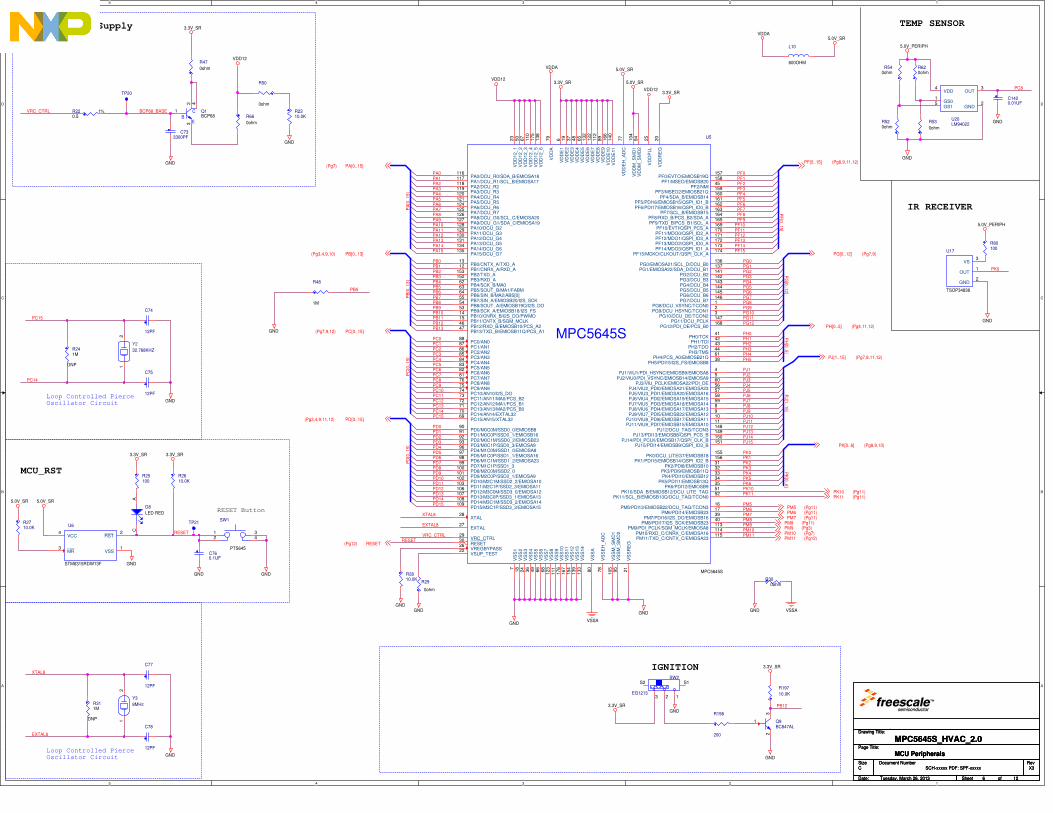
Loop Controlled PierceOscillator Circuit
Loop Controlled PierceOscillator Circuit
RESET Button
IR RECEIVER
TEMP SENSOR
IGNITION
MCU Internal Supply
MCU_RST
RESET
PC15
PC14
XTAL8
EXTAL8
PA0PA1PA2PA3PA4PA5PA6PA7PA8PA9PA10PA11PA12PA13PA14PA15
PA
[0..
15]
PB
[0..
13]
PB0PB1PB2PB3PB4PB5PB6PB7PB8PB9PB10PB11PB12PB13
PC
[0..
15]
PC0PC1PC2PC3PC4PC5PC6PC7PC8PC9PC10PC11PC12PC13PC14PC15
PD
[0..
15]
PD0PD1PD2PD3PD4PD5PD6PD7PD8PD9PD10PD11PD12PD13PD14PD15
XTAL8
EXTAL8
RESET
PF0PF1PF2PF3PF4PF5PF6PF7PF8PF9
PF10PF11PF12PF13PF14PF15
PF
[0..1
5]
PG
[0..1
2]
PG0PG1
PG3PG4
PG6
PG2
PG7
PG9
PG11PG12
PG10
PG8
PG5
PH0PH1PH2PH3PH4
PH
[0..5
]
PH5
PJ[1
..15]
PJ1PJ2PJ3PJ4PJ5PJ6PJ7PJ8PJ9PJ10PJ11PJ12PJ13PJ14PJ15
PK
[0..6
]
PK0PK1PK2PK3PK4PK5PK6PK10PK11
PM5PM6
PM8PM9PM10PM11
PM7
BCP68_BASEVRC_CTRL
VRC_CTRL
PB5
PC8
PK0
PB12
GND
5.0V_SR 5.0V_SR
GND
GND
3.3V_SR3.3V_SR
GND GND
GND
VSSAGND
VSSA
GND
5.0V_SRVDDA
VDD12
GND
GND
3.3V_SR
GNDGND
VDD12
VDDA
3.3V_SR
5.0V_SR
5.0V_SR
VDD123.3V_SR
GND
GND
GND
GND
5.0V_PERIPH
5.0V_PERIPH
GND
GND
3.3V_SR
3.3V_SR
PA[0..15](Pg7)
PB[0..13](Pg3,4,9,10)
PC[0..15](Pg7,9,12)
PD[0..15](Pg3,4,9,11,12)
RESET(Pg12)
PF[0..15] (Pg8,9,11,12)
PG[0..12] (Pg7,9)
PH[0..5] (Pg4,11,12)
PJ[1..15] (Pg7,8,11,12)
PK[0..6] (Pg8,9,10)
PK10 (Pg11)PK11 (Pg11)
PM5 (Pg11)PM6 (Pg11)
PM8 (Pg11)PM9 (Pg3)PM10 (Pg7)PM11 (Pg12)
PM7 (Pg11)
Drawing Title:
Size Document Number Rev
Date: Sheet of
Page Title:
i
SCH-xxxxx PDF: SPF-xxxxx X3
MPC5645S_HVAC_2.0
C
Tuesday, March 26, 2013
MCU Peripherals
6 12
Drawing Title:
Size Document Number Rev
Date: Sheet of
Page Title:
i
SCH-xxxxx PDF: SPF-xxxxx X3
MPC5645S_HVAC_2.0
C
Tuesday, March 26, 2013
MCU Peripherals
6 12
Drawing Title:
Size Document Number Rev
Date: Sheet of
Page Title:
i
SCH-xxxxx PDF: SPF-xxxxx X3
MPC5645S_HVAC_2.0
C
Tuesday, March 26, 2013
MCU Peripherals
6 12
C75
12PF
R540ohm
C78
12PF
R25100
R311M
DNP
R620ohm
R66
0ohm
C733300PF
EB
C Q1BCP68
1
32 4
C77
12PF
C760.1UF
U17
TSOP34838
GND2
OUT1
VS3
R80100
R241M
DNP
R220.5
1%
R197
10.0K
R2710.0K U6
STM6315RDW13F
VCC4
RST2
VSS1
MR3
32.768KHZ
Y2
12
LM94022U20
VDD4
GS15
GND2
OUT3
GS01
Q9BC847AL
23
1
TP20
R48
1M
Y3
8MHz
12
R520ohm
R2310.0K
C1420.01UF
MPC5645S
U5
MPC5645S
PA0/DCU_R0/SDA_B/EMIOSA18116
PA1/DCU_R1/SCL_B/EMIOSA17117
PA10/DCU_G2128
PA11/DCU_G3129
PA12/DCU_G4130
PA13/DCU_G5131
PA14/DCU_G6134
PA15/DCU_G7135
PA2/DCU_R2118
PA3/DCU_R3119
PA4/DCU_R4120
PA5/DCU_R5121
PA6/DCU_R6124
PA7/DCU_R7125
PA8/DCU_G0/SCL_C/EMIOSA20126
PA9/DCU_G1/SDA_C/EMIOSA19127
PB0/CNTX_A/TXD_A13
PB1/CNRX_A/RXD_A12
PB2/TXD_A153
PB3/RXD_A152
PB4/SCK_B/MA062
PB5/SOUT_B/MA1/FABM63
PB6/SIN_B/MA2/ABS[0]64
PB7/SIN_A/EMIOSB20/I2S_SCK55
PB8/SOUT_A/EMIOSB19Q/I2S_DO54
PB9/SCK_A/EMIOSB18/I2S_FS53
PC0/AN088
PC1/AN187
PC10/AN10/I2S_DO74
PC11/AN11/MA0/PCS_B273
PC12/AN12/MA1/PCS_B172
PC13/AN13/MA2/PCS_B071
PC14/AN14/EXTAL3270
PC15/AN15/XTAL3269
PC2/AN286
PC3/AN385
PC4/AN484
PC5/AN583
PC6/AN682
PC7/AN781
PC8/AN876
PC9/AN975
PD0/M0C0M/SSD0_0/EMIOSB890
PD1/M0C0P/SSD0_1/EMIOSB1691
PD10/M2C1M/SSD2_2/EMIOSA10102
PD11/M2C1P/SSD2_3/EMIOSA11103
PD12/M3C0M/SSD3_0/EMIOSA12106
PD13/M3C0P/SSD3_1/EMIOSA13107
PD14/M3C1M/SSD3_2/EMIOSA14108
PD15/M3C1P/SSD3_3/EMIOSA15109
PD2/M0C1M/SSD0_2/EMIOSB2392
PD3/M0C1P/SSD0_3/EMIOSA993
PD4/M1C0M/SSD1_0/EMIOSA896
PD5/M1C0P/SSD1_1/EMIOSA1697
PD6/M1C1M/SSD1_2/EMIOSA2398
PD7/M1C1P/SSD1_399
PD8/M2C0M/SSD2_0100
PD9/M2C0P/SSD2_1/EMIOSA9101
PG6/DCU_B6145
PG7/DCU_B7146
PG8/DCU_VSYNC/TCON01
PG9/DCU_HSYNC/TCON12
PH0/TCK41
PH1/TDI42
PH2/TDO43
PH3/TMS44
PH4/PCS_A0/EMIOSB21Q61
PH5/PDI15/I2S_FS/EMIOSB838
PJ1/VIU1/PDI_HSYNC/EMIOSB9/EMIOSA84
PJ2/VIU0/PDI_VSYNC/EMIOSB14/EMIOSA95
PJ3/VIU_PCLK/EMIOSA22/PDI_DE60
PJ4/VIU2_PDI0/EMIOSA21/EMIOSA2356
PJ5/VIU3_PDI1/EMIOSA20/EMIOSA1657
PJ6/VIU4_PDI2/EMIOSA19/EMIOSA1558
PJ7/VIU5_PDI3/EMIOSA18/EMIOSA1459
PJ8/VIU6_PDI4/EMIOSA17/EMIOSA138
PJ9/VIU7_PDI5/EMIOSB22/EMIOSA129
PK0/DCU_LITEG7/EMIOSB18155
PK1/PDI15/EMIOSB14/QSPI_IO2_B156
PK2/PDI8/EMIOSB1031
PK3/PDI9/EMIOSB11Q32
PK4/PDI10/EMIOSB1233
PK5/PDI11/EMIOSB13Q34
PK6/PDI12/EMIOSB935
PM5/PDI13/EMIOSB22/DCU_TAG/TCON316
PM6/PDI14/EMIOSB2317
PM7/PDI16/I2S_DO/EMIOSB1639
PM8/PDI17/I2S_SCK/EMIOSB2340
PM9/PDI_PCLK/SGM_MCLK/EMIOSA8113
VS
S1
7
VS
S2
18
VS
S3
24
VS
S4
36
VS
S5
49
VS
S6
66
VS
S7
68
VS
S8
123
VS
S9
111
VS
S10
176
VS
S11
167
VS
S12
154
VS
S13
139
VS
S14
133
VS
SA
80
VS
SE
H_A
DC
78
VS
SM
_S
MD
1105
VS
SM
_S
MD
295
VS
SR
EG
21
VD
D12_1
23
VD
D12_2
50
VD
D12_3
67
VD
D12_4
110
VD
D12_5
175
VD
D12_6
138
VD
DA
79
VD
DE
16
VD
DE
219
VD
DE
337
VD
DE
448
VD
DE
565
VD
DE
6132
VD
DE
7122
VD
DE
8112
VD
DE
989
VD
DE
10
166
VD
DE
11
140
VD
DE
H_A
DC
77
VD
DM
_S
MD
1104
VD
DM
_S
MD
294
VD
DP
LL
25
VD
DR
EG
20
PF0/EVTO/EMIOSB19Q157
PF1/MSEO/EMIOSB20158
PF2/NMI45
PF3/MSEO2/EMIOSB21Q159
PF4/SDA_B/EMIOSB14160
PF5/PDI16/EMIOSB15/QSPI_IO1_B161
PF6/PDI17/EMIOSB16/QSPI_IO0_B162
PF7/SCL_B/EMIOSB15163
PF8/RXD_B/PCS_B2/SDA_A164
PF9/TXD_B/PCS_B1/SCL_A165
PG0/EMIOSA21/SCL_D/DCU_B0136
PG1/EMIOSA22/SDA_D/DCU_B1137
PG2/DCU_B2141
PG3/DCU_B3142
PG4/DCU_B4143
PG5/DCU_B5144
PB10/CNRX_B/I2S_DO/PWMO14
PB11/CNTX_B/SGM_MCLK15
PB12/RXD_B/EMIOSB10/PCS_A246
PB13/TXD_B/EMIOSB11Q/PCS_A147
PF10/EVTI/QSPI_PCS_A169
PF11/MDO0/QSPI_IO2_A170
PF12/MDO1/QSPI_IO3_A171
PF13/MDO2/QSPI_IO0_A172
PF14/MDO3/QSPI_IO1_A173
PF15/MCKO/CLKOUT/QSPI_CLK_A174
PG10/DCU_DE/TCON23
PG11/DCU_PCLK147
PG12/PDI_DE/PCS_B0168
PK10/SDA_B/EMIOSB12/DCU_LITE_TAG51
PK11/SCL_B/EMIOSB13Q/DCU_TAG/TCON052
PM10/RXD_C/CNRX_C/EMIOSA16114
PM11/TXD_C/CNTX_C/EMIOSA23115
XTAL28
EXTAL27
VRC_CTRL29
RESET30
VREGBYPASS26
VSUP_TEST22
PJ10/VIU8_PDI6/EMIOSB17/EMIOSA1110
PJ11/VIU9_PDI7/EMIOSB15/EMIOSA1011
PJ12/DCU_TAG/TCON3148
PJ13/PDI13/EMIOSB8/QSPI_PCS_B149
PJ14/PDI_PCLK/EMIOSB17/QSPI_CLK_B150
PJ15/PDI14/EMIOSB9/QSPI_IO3_B151
L10
600OHM
TP21
D8
LED RED
AC
R50
0ohm
R2610.0K
SW2
EG1213123
S1S2
R53
0ohm
SW1
PTS645
12
34
R29
0ohm
C74
12PF
R198
200
R300ohm
R2810.0K
R47
0ohm
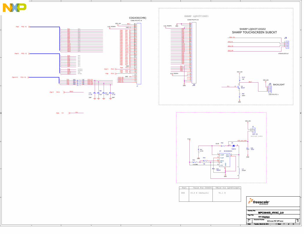
5
5
4
4
3
3
2
2
1
1
D D
C C
B B
A A
(R1)
(R2)
(R3)
(R4)
(R5)
(R6)
(R7)
(G0)
(G1)
(G2)
(G3)
(G4)
(G5)
(G6)
(G7)
(B0)
(B1)
(B2)
(B3)
(B4)
(B5)
(B6)
(B7)
(VSYNC)
(HSYNC)
(DE)
(PCLK)
(R0)
Backlight enable
BACKLIGHT
SHARP LQ043T1DG02
SHARP TOUCHSCREEN SUBCKT
R40
Part
33.0 K (Default) 51.1 K
Value For COG430 VAlue for LQ043t1dg01
COG430(CHN)SHARP LQ043T1DG01
PA2PA3PA4PA5PA6PA7
PA10PA11PA12PA13PA14PA15
PG2PG3PG4PG5PG6PG7
PG8PG9PG10PG11
DCU_YDDCU_XR
DCU_XLDCU_YUPC0
PC1PC2PC3
PA1PA0
VDD_20V_HDR
PA8PA9
PG0PG1
DCU_YU
DCU_XL
DCU_YD
DCU_XR
PA0PA1PA2PA3PA4PA5PA6PA7PA8PA9PA10PA11PA12PA13PA14PA15PG0PG1PG2PG3PG4PG5PG6PG7
PG11PG10PG9PG8
DCU_XL
BKLT
DCU_XRDCU_YD
DCU_YU BKLT
PM10
PJ1
PJ1
P12V
GND
VDD_20V
GND
GND
VDD_20V
GND
GND
GND
GND
GND
GND
VDD_20V
VDD_20V
3.3V_PERIPH
5.0V_PERIPH
3.3V_PERIPHPA[0..15](Pg6)
PG[0..12](Pg6,9)
PC[0..15](Pg6,9,12)
PA0(Pg6)PA1(Pg6)PA2(Pg6)PA3(Pg6)PA4(Pg6)PA5(Pg6)
PA9(Pg6)PA8(Pg6)
PA10(Pg6)PA11(Pg6)PA12(Pg6)PA13(Pg6)
PG0(Pg6)PG1(Pg6)PG2(Pg6)PG3(Pg6)PG4(Pg6)PG5(Pg6)
PA6(Pg6)PA7(Pg6)
PA15(Pg6)PA14(Pg6)
PG6(Pg6)PG7(Pg6)
PG11(Pg6)PM10(Pg6,7)
PG9(Pg6)PG8(Pg6)
PG10(Pg6)
PM10(Pg6,7)
PJ1(Pg6)
Drawing Title:
Size Document Number Rev
Date: Sheet of
Page Title:
i
SCH-xxxxx PDF: SPF-xxxxx X3
MPC5645S_HVAC_2.0
C
Tuesday, March 26, 2013
TFT Displays
7 12
Drawing Title:
Size Document Number Rev
Date: Sheet of
Page Title:
i
SCH-xxxxx PDF: SPF-xxxxx X3
MPC5645S_HVAC_2.0
C
Tuesday, March 26, 2013
TFT Displays
7 12
Drawing Title:
Size Document Number Rev
Date: Sheet of
Page Title:
i
SCH-xxxxx PDF: SPF-xxxxx X3
MPC5645S_HVAC_2.0
C
Tuesday, March 26, 2013
TFT Displays
7 12
R65
0ohm
J5
CON FPC/FFC 4
1234C80
1.0UFC820.1UF
DNP
J2
CONN FPC/FFC 40
123456789
10111213141516171819202122232425262728293031323334353637383940
C811.0UF
J4
HFW4R-2STE1LF
1234
R42
1.5 OHM
R36 100
R4033.0K
R38 100
U7 MC33063ADG
COMP5
TCAP3
VCC6
GN
D4
DRVC8
IPK7
SWC1
SWE2
J6
HDR 1X2
12
R43
180
R412.21K
R127
100
D9
1N5819
AC
Q2BC547
2
31
C841500PF
L11270UH
12
R37 100
C790.1UF
DNP
R39 100
+ C83100uF
J3
CONN FPC/FFC 40
123456789
10111213141516171819202122232425262728293031323334353637383940
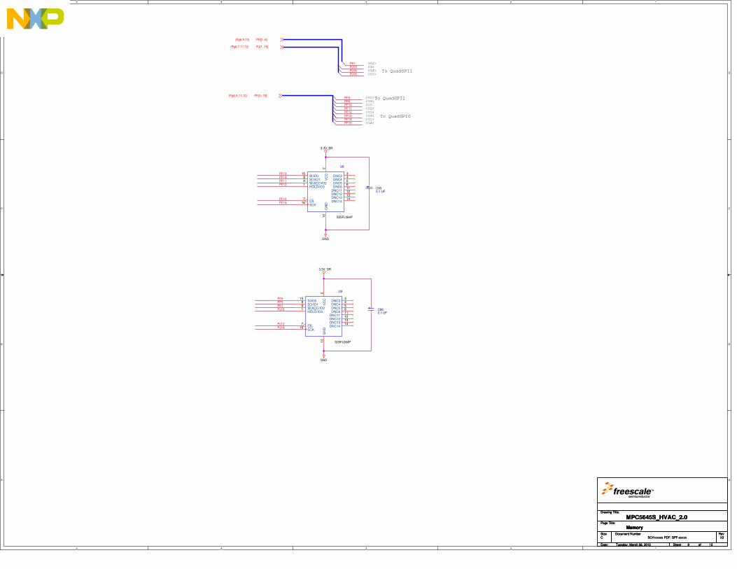
5
5
4
4
3
3
2
2
1
1
D D
C C
B B
A A
To QuadSPI0
(CS)
(IO2)
(IO3)
(IO0)
(IO1)
(CLK)
(IO1)
(IO0)To QuadSPI1
(CS)
(IO2)
(IO3)
(CLK) To QuadSPI1
PF10PF11PF12PF13PF14PF15
PF13PF14PF11PF12
PF10PF15
PF6PF5PK1PJ15
PJ13PJ14
PF5PF6
PJ15
PJ13PJ14
PK1
GND
3.3V_SR
GND
3.3V_SR
PF[0..15](Pg6,9,11,12)
PJ[1..15](Pg6,7,11,12)
PK[0..6](Pg6,9,10)
Drawing Title:
Size Document Number Rev
Date: Sheet of
Page Title:
i
SCH-xxxxx PDF: SPF-xxxxx X3
MPC5645S_HVAC_2.0
C
Tuesday, March 26, 2013
Memory
8 12
Drawing Title:
Size Document Number Rev
Date: Sheet of
Page Title:
i
SCH-xxxxx PDF: SPF-xxxxx X3
MPC5645S_HVAC_2.0
C
Tuesday, March 26, 2013
Memory
8 12
Drawing Title:
Size Document Number Rev
Date: Sheet of
Page Title:
i
SCH-xxxxx PDF: SPF-xxxxx X3
MPC5645S_HVAC_2.0
C
Tuesday, March 26, 2013
Memory
8 12
C850.1 UF
S25FL064P
U9
HOLD/IO31
CS7
SO/IO18
W/ACC/IO29
SI/IO015
SCK16
DNC33
DNC44
DNC55
DNC66
DNC1111
DNC1212
DNC1313
DNC1414
VC
C2
GN
D10
S25FL064P
U8
HOLD/IO31
CS7
SO/IO18
W/ACC/IO29
SI/IO015
SCK16
DNC33
DNC44
DNC55
DNC66
DNC1111
DNC1212
DNC1313
DNC1414
VC
C2
GN
D10
C860.1 UF
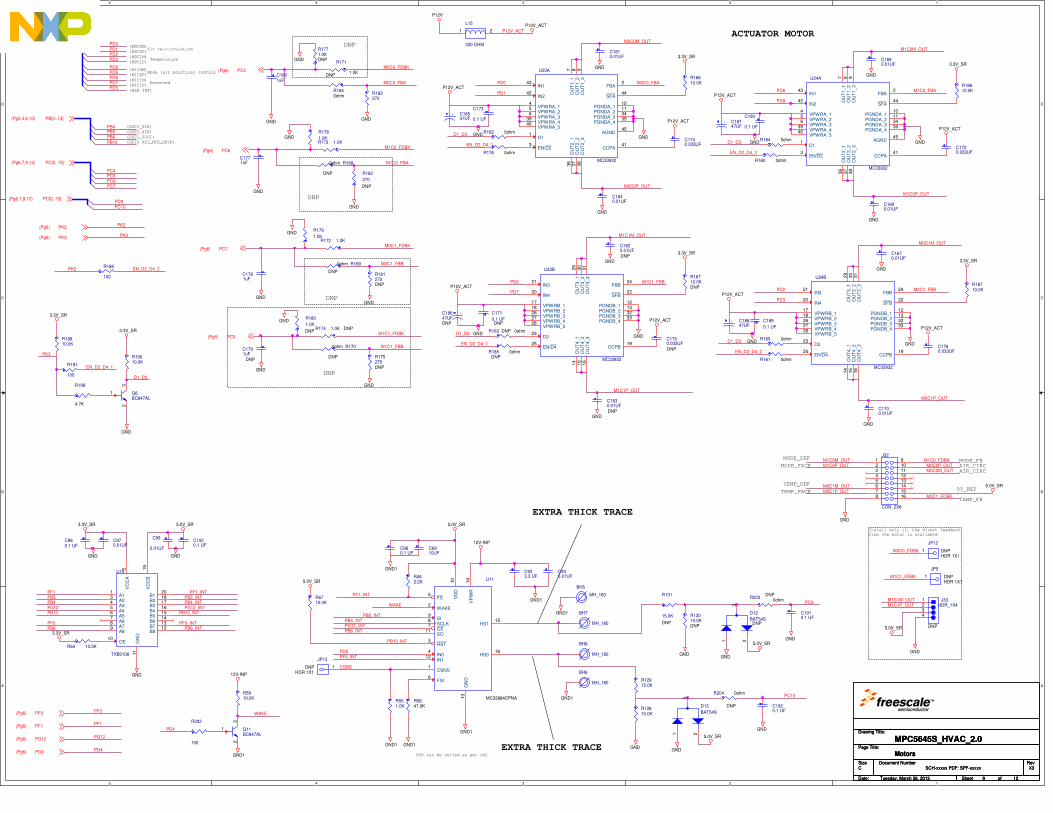
5
5
4
4
3
3
2
2
1
1
D D
C C
B B
A A
(M0C0M)
(M0C0P)
(M0C1M)
(M0C1P)
(M1C0M)
(M1C0P)
(M1C1P)
(M1C1M)
(DSPI_SCK)
(DSPI_SIN)
(DSPI_SOUT)
EXTRA THICK TRACE
EXTRA THICK TRACE
(GPIO RST_MTR_DRVR)
R56 can be veried as per ckt
Air re-circulation
Temperature
Mode (air position) control
Reserved
DNP
DNP
DNP
DNP
ACTUATOR MOTOR
Install only if, the direct feedback from the motor is available
(BLR INT)
MODE_DEF
MODE_FACE
TEMP_DEF
TEMP_FACE
MODE_FBAIR_CIRC
5V_REF
TEMP_FB
AIR_CIRC
PD0PD1PD2PD3
PD8PD9PD6PD7
PB4_INTPG12_INT
PB10_INT
PD5PF0_INT
WAKE
PB4PB5PB6
PC4
PB10
PF1_INTPB5PB4PG12PB10
PF0
PF1PB5_INTPB4_INTPG12_INT
PF1_INT
PB10_INT
PF0_INT
PB6_INT
PB5_INT
PB6 PB6_INT
CSNS
PF0
PK3
PF1
PC9PC10
EN_D2_D4_2
M1C0P_OUT
M1C0M_OUT
EN_D2_D4_2
M1C0_FBA
M0C1_FBBPD2
PD3
M0C1P_OUT
M0C1M_OUT
M1C0M_OUTM1C0P_OUT
M0C1M_OUTM0C1P_OUT
M0C0P_OUTM0C0M_OUT
D1_D3
D1_D3
D1_D3
PD0
PD1
D1_D3
M0C1_FBB
M1C1_FBB
EN_D2_D4_1
M0C0_FDBK
M0C0P_OUT
M1C0_FDBK
M0C1_FDBK
M1C1_FDBK
M0C0M_OUT
M0C0_FBA
M1C0_FBA
EN_D2_D4_1
M0C0_FBA
M1C1_FBBPD6
PD7
M1C1P_OUT
M1C1M_OUT
PD8
PD9
PK2 EN_D2_D4_2
PK3
EN_D2_D4_1
D1_D3
P12V_ACT
PK2
M0C0_FDBK
M1C1_FDBK
M1C1P_OUTM1C1M_OUT
PG12
PC5PC6PC7
PC9
PC10
PD4
WAKE
PD4
PD5
M0C1_FDBK
M1C0_FDBK
GND1
GND1
GND1
GND1
GND1
12V-INP
GND1
GND1
GND
GNDGND
3.3V_SR 5.0V_SR
3.3V_SR
5.0V_SR
5.0V_SR
GNDGND
GNDGND
5.0V_SR
5.0V_SR
GND
GND
GND
GND
GND
GND
GND
P12V_ACT
P12V_ACT
P12V_ACT
GND
GND
P12V_ACT
P12V_ACT
P12V_ACT
GND
GND
GND
GND
GND
GND
GND
GND
GND
GND
GND
GND
GND
GND
GND
GND
GND
GND
P12V_ACT
P12V_ACT
GND
GND
GND
P12V
P12V_ACT
GND
3.3V_SR
3.3V_SR
3.3V_SR
3.3V_SR
3.3V_SR
3.3V_SR
GND
GND
12V-INP
5.0V_SR
5.0V_SR
GND1
PD[0..15](Pg3,4,6,11,12)
PB[0..13](Pg3,4,6,10)
PC[0..15](Pg6,7,9,12)
PF0(Pg6)
PK3(Pg6)
PF1(Pg6)
PC[0..15](Pg6,7,9,12)
PC4(Pg6)
PC6(Pg6)
PC7(Pg6)
PC5(Pg6)
PK2(Pg6)
PG12(Pg6)
PD4(Pg6)
Drawing Title:
Size Document Number Rev
Date: Sheet of
Page Title:
i
SCH-xxxxx PDF: SPF-xxxxx X3
MPC5645S_HVAC_2.0
C
Tuesday, March 26, 2013
Motors
9 12
Drawing Title:
Size Document Number Rev
Date: Sheet of
Page Title:
i
SCH-xxxxx PDF: SPF-xxxxx X3
MPC5645S_HVAC_2.0
C
Tuesday, March 26, 2013
Motors
9 12
Drawing Title:
Size Document Number Rev
Date: Sheet of
Page Title:
i
SCH-xxxxx PDF: SPF-xxxxx X3
MPC5645S_HVAC_2.0
C
Tuesday, March 26, 2013
Motors
9 12
R199
4.7K
R191
100
C1910.1 UF
C1750.033UF
DNP
R176 0ohm
C1830.01UF
DNP
BH8
MH_180
C189
0.1 UF
C923.3 UF
R16710.0KDNP
C880.1 UF
C1840.01UF
R181270DNP
R1840ohm
U23B
MC33932
IN321
IN420
VPWRB_117
VPWRB_218
VPWRB_326
VPWRB_427
VPWRB_528
D323
EN/D425
OU
T3_1
29
OU
T3_2
30
OU
T3_3
31
CCPB19
PGNDB_112
PGNDB_213
PGNDB_332
PGNDB_433
FBB24
SFB22
OU
T4_1
14
OU
T4_2
15
OU
T4_3
16
+ C18547UF
C1760.033UF
R5647.0K
C171
0.1 UFDNP
R1771.0KDNP
C930.01UF
R182
270
DNP
R171
1.0KDNP
D13
BAT54S
1
3
2
C190
0.1 UF
+C18647UFDNP
R188
100
R2030ohm
DNP
JP5
HDR 1X1DNP1
R12810.0K
C970.01UF
R551.0K
R183270
R64 10.0K
R172 1.0K
+ C18747UF
C1670.01UF
C980.1 UF
R162 0ohm
R12915.0K
C1720.033UF
R178
1.0K
C1771uF
R173 1.0K
R204 0ohm
DNP
C1680.01UF
Q11BC847AL
23
1
+ C18847UF
R185 0ohmDNP
R1680ohm
DNP
R462.2K
R13010.0KDNP
C1781uF
R18910.0K
R163 0ohmDNP
C1690.01UF
R5910.0K
R179
1.0K
C173
0.1 UF
C99
0.01UF
Q6BC847AL
23
1
L15
330 OHM
1 2
R174 1.0K DNP
C1791uF
DNP
C1920.1 UF
R131
15.0K
DNP
R18610.0K
R1690ohm
DNP
U24A
MC33932
IN143
IN242
VPWRA_14
VPWRA_25
VPWRA_36
VPWRA_439
VPWRA_540
D11
EN/D23
OU
T1_1
7
OU
T1_2
8
OU
T1_3
9
CCPA41
PGNDA_110
PGNDA_211
PGNDA_334
PGNDA_435
AGND45
FBA2
SFA44
OU
T2_1
36
OU
T2_2
37
OU
T2_3
38
C1000.1 UF
U11
MC33984CPNA
CSNS1
WAKE2
RST3
FS5
FSI6
VD
D10
GN
D13
VP
WR
14
HS115
HS016
IN04
IN112
SI9
SCLK8
CS7
SO11
R202
100
C1801uF
J32
CON_2X8
12345678
910111213141516
R180
1.0K
DNP
R164 0ohm
U23A
MC33932
IN143
IN242
VPWRA_14
VPWRA_25
VPWRA_36
VPWRA_439
VPWRA_540
D11
EN/D23
OU
T1_1
7
OU
T1_2
8
OU
T1_3
9
CCPA41
PGNDA_110
PGNDA_211
PGNDA_334
PGNDA_435
AGND45
FBA2
SFA44
OU
T2_1
36
OU
T2_2
37
OU
T2_3
38
C1700.01UF
R19010.0K
JP13
HDR 1X1DNP 1
JP12
HDR 1X1DNP1
D12
BAT54SDNP
1
3
2
R18710.0K
R6710.0K
R165 0ohm
R160 0ohm
BH5
MH_180
C8910UF
R16610.0K
R175270DNP
C1810.01UF
U19
TXB0108
VC
CA
2
A11
A23
A34
A45
GN
D11
OE10
B416B317B218B120
VC
CB
19
A56
A67
A78
A89
B812B713B614B515
BH6
MH_180
C1740.033UF
R161 0ohm
BH7
MH_180
R1700ohm
DNP
J33HDR_1X4
DNP
1234
C1820.01UF
DNP
U24B
MC33932
IN321
IN420
VPWRB_117
VPWRB_218
VPWRB_326
VPWRB_427
VPWRB_528
D323
EN/D425
OU
T3_1
29
OU
T3_2
30
OU
T3_3
31
CCPB19
PGNDB_112
PGNDB_213
PGNDB_332
PGNDB_433
FBB24
SFB22
OU
T4_1
14
OU
T4_2
15
OU
T4_3
16
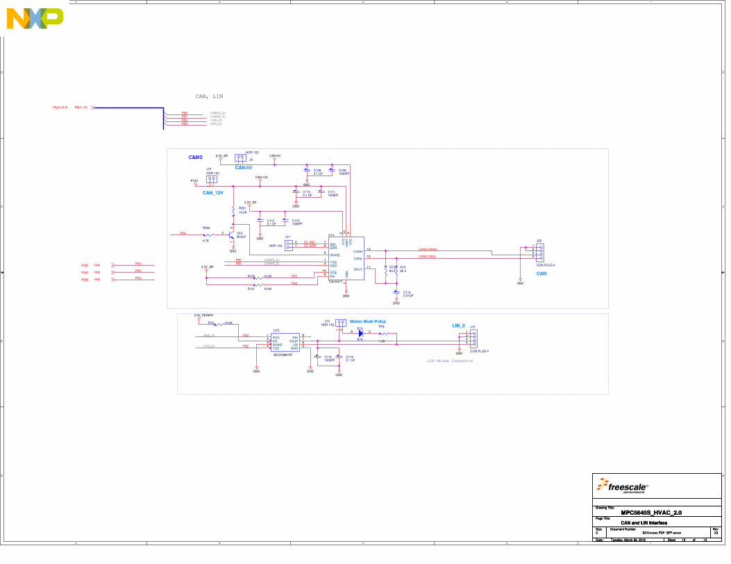
5
5
4
4
3
3
2
2
1
1
D D
C C
B B
A A
CAN, LIN
(CANTX_0)
(CANRX_0)
(TXD_0)
(RXD_0)
CAN0
(CANTX_0)
(CANRX_0)
(TXD_0)
(RXD_0)
LIN Molex Connector
PB0PB1PB2PB3
PK6
PK5
CAN0-CANL
C0_INHC0_ERR
CAN0-CANH
PB0PB1
PB3
PB2
PK4
PK5
PK6
PK4
GND
CAN-12V
CAN-5V
P12V
GND
GND
GND
GND
5.0V_SR
GNDGNDGND
3.3V_SR
GND
GND
GND
3.3V_PERIPH
3.3V_SR
PB[0..13](Pg3,4,6,9)
PK4(Pg6)
PK5(Pg6)
PK6(Pg6)
Drawing Title:
Size Document Number Rev
Date: Sheet of
Page Title:
i
SCH-xxxxx PDF: SPF-xxxxx X3
MPC5645S_HVAC_2.0
C
Tuesday, March 26, 2013
CAN and LIN Interface
10 12
Drawing Title:
Size Document Number Rev
Date: Sheet of
Page Title:
i
SCH-xxxxx PDF: SPF-xxxxx X3
MPC5645S_HVAC_2.0
C
Tuesday, March 26, 2013
CAN and LIN Interface
10 12
Drawing Title:
Size Document Number Rev
Date: Sheet of
Page Title:
i
SCH-xxxxx PDF: SPF-xxxxx X3
MPC5645S_HVAC_2.0
C
Tuesday, March 26, 2013
CAN and LIN Interface
10 12
C1160.1 UF
Q10BC547
23
1
C1111000PF
C1151000PF
C1120.1 UF
J10
HDR 1X2
CAN_12V
1 2
C1131000PF
J15
CON PLUG 4
LIN_0
1234
C1100.1 UF
R75 10.0K
D10
S1A
A C
J35
CON PLUG 4
CAN
1234
C1140.01UF
R76
1.0K
J14HDR 1X2
Master Mode Pullup
1 2
R120 10.0K
C1080.1 UF
R7360.4
C1091000PF
J9
HDR 1X2
CAN-5V
1 2J11
HDR 1X2 12
R201
10.0K
R7460.4
U15
MCZ33661EF
RXD1
EN2
WAKE3
TXD4
GND5LIN6VSUP7INH8
R121 10.0K
R200
4.7K
U14
TJA1041T
INH7
WAKE9
STB14
EN6
TXD1
ERR8
RXD4
GN
D2
SPLIT11
CANH13
CANL12
VI/O
5
VB
AT
10
VC
C3
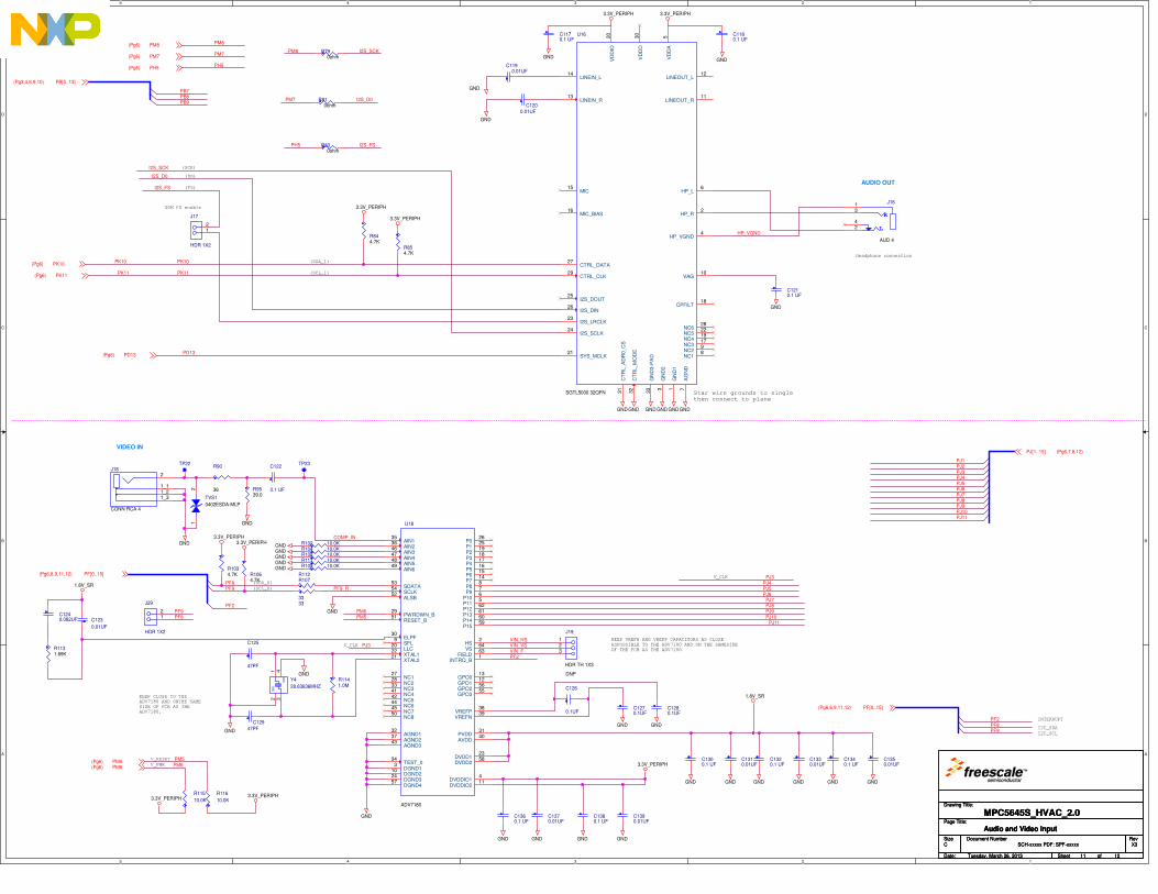
5
5
4
4
3
3
2
2
1
1
D D
C C
B B
A A
INTERRUPT
I2C_SDA
I2C_SCL
V_CLK
V_CLK
(SCL_0)
(SDA_0)
KEEP CLOSE TO THEADV7180 AND ONTHE SAMESIDE OF PCB AS THEADV7180.
V_RESET
V_PWR
KEEP VREFN AND VREFP CAPACITORS AS CLOSEASPOSSIBLE TO THE ADV7180 AND ON THE SAMESIDEOF THE PCB AS THE ADV7180
Headphone connection
(SDA_1)
(SCL_1)
Star wire grounds to singlethen connect to plane
(SCK)
(DO)
(FS)
SGM FS enable
PF2PF8PF9
PF9PJ6
PJ7
PM5
PJ10PJ11
PJ8PJ9
PM6
COMP_IN
PJ3PJ4PJ5PJ6PJ7PJ8PJ9PJ10PJ11
PJ2PJ1
PF9_R
PF2
PF2
PJ3
PJ3
PM6
VIN_F
PM5
PF8
VIN_VSVIN_HS
PJ4PJ5
PK10PK10
PK11PK11
PB7
PB9PB8
I2S_SCK
I2S_D0
I2S_SCK
I2S_FS
I2S_D0PM7
I2S_FSPH5
PD13
HP_VGND
PM8
PM8
PM7
PH5
PF8PF9
GND
GND
GND
1.8V_SR
GND
GNDGND
GND GND
GND GND
GND
GND GND GND GND
GND
1.8V_SR
GND
GND GND
GNDGND
GND
GND
GND
GND
GND
GNDGND
GNDGNDGNDGNDGNDGND
3.3V_PERIPH
3.3V_PERIPH
3.3V_PERIPH3.3V_PERIPH
3.3V_PERIPH3.3V_PERIPH
3.3V_PERIPH3.3V_PERIPH
3.3V_PERIPH
PF[0..15](Pg6,8,9,11,12)
PJ[1..15] (Pg6,7,8,12)
PM5(Pg6)PM6(Pg6)
PF[0..15](Pg6,8,9,11,12)
PK10(Pg6)
PK11(Pg6)
PB[0..13](Pg3,4,6,9,10)
PD13(Pg6)
PM8(Pg6)
PM7(Pg6)
PH5(Pg6)
Drawing Title:
Size Document Number Rev
Date: Sheet of
Page Title:
i
SCH-xxxxx PDF: SPF-xxxxx X3
MPC5645S_HVAC_2.0
C
Tuesday, March 26, 2013
Audio and Video Input
11 12
Drawing Title:
Size Document Number Rev
Date: Sheet of
Page Title:
i
SCH-xxxxx PDF: SPF-xxxxx X3
MPC5645S_HVAC_2.0
C
Tuesday, March 26, 2013
Audio and Video Input
11 12
Drawing Title:
Size Document Number Rev
Date: Sheet of
Page Title:
i
SCH-xxxxx PDF: SPF-xxxxx X3
MPC5645S_HVAC_2.0
C
Tuesday, March 26, 2013
Audio and Video Input
11 12
R1064.7K
C1180.1 UF
R102 10.0K
C1240.082UF
U18
ADV7180
AIN135
AIN236
AIN346
AIN447
AIN548
AIN649
SDATA53
SCLK54
ALSB52
ELPF30
SFL9
LLC20
XTAL122
XTAL221
NC127
NC228
NC333
NC441
NC542
NC644
NC745
NC850
AGND132
AGND237
AGND343
TEST_034
DGND13
DGND210
DGND324
DGND457
P026
P125
P219
P318
P417
P516
P615
P714
P88
P97
P106
P115
P1262
P1361
P1460
HS2
VS64
FIELD63
INTRQ_B1
GPO013
GPO112
GPO256
GPO355
VREFP38
VREFN39
PVDD31
AVDD40
DVDD123
DVDD258
DVDDIO211DVDDIO14
P1559
PWRDWN_B29
RESET_B51
C1340.1 UF
C1370.01UF
C126
0.1UF
R107
33
C1320.1 UF
R830ohm
GN
D
GN
D
Y4
28.63636MHZ
12 3
4
C120
0.01UF
C1300.1 UF
C1210.1 UF
R9539.0
TP22
C1360.1 UF
C1190.01UF
R90
36
R105 10.0K
J29
HDR 1X2
12
C1170.1 UF
J17
HDR 1X2
12
C1380.1 UF
R1141.0M
TP23
R108 10.0K
R
L
J16
AUD 4
AUDIO OUT
1
2
3
4
R790ohm
TVS1
0402ESDA-MLP
12
C122
0.1 UF
R112
33
R111 10.0K
J19
HDR TH 1X3
DNP
123
C1390.01UF
C123
0.01UF
R104 10.0K
C125
47PF
U16
SGTL5000 32QFN
I2S_SCLK24
NC522
LINEIN_L14
CPFILT18
VD
DIO
20
NC419
SYS_MCLK21
I2S_DOUT25
I2S_DIN26
HP_L6
CTRL_DATA27
NC628
CTRL_CLK29
GN
D1
1
NC18
HP_R2
GN
D2
3
VD
DA
5
LINEOUT_L12
LINEOUT_R11
MIC15
NC317
LINEIN_R13
AG
ND
7
I2S_LRCLK23
VD
DD
30
CT
RL_A
DR
0_C
S31
CT
RL_M
OD
E32
HP_VGND4
NC29
VAG10
MIC_BIAS16
GN
D3-P
AD
33
C1270.1UF
J18
CONN RCA 4
VIDEO IN
2
1_11_21_3
R115
10.0K
C1310.01UF
R1034.7K
R844.7K
C129
47PF
C1330.01UF
C1280.1UF
R810ohm
R1131.69K
R854.7K
C1350.01UF
R116
10.0K
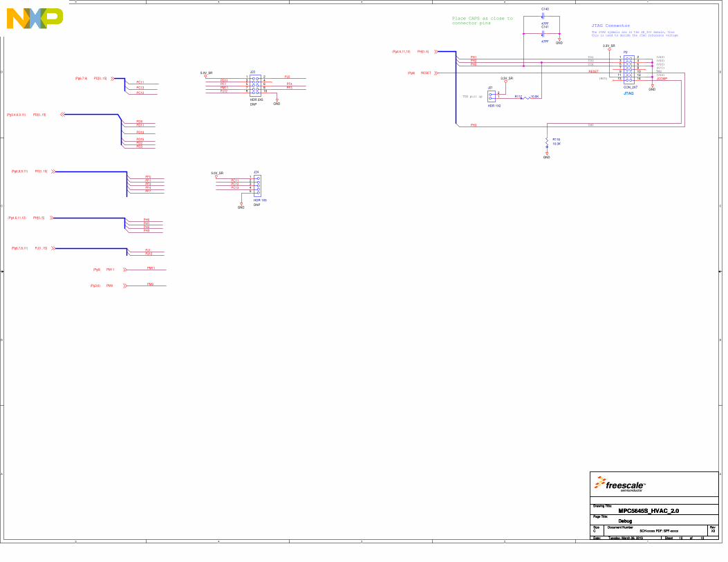
5
5
4
4
3
3
2
2
1
1
D D
C C
B B
A A
The JTAG symbols are in the SR_3V3 domain, thusthis is used to decide the JTAG reference voltage
(RDY)
Place CAPS as close toconnector pins
JTAG Connector
(N/C)
(VSS)
(VSS)
(VSS)
(VSS)TDI
TDO
TCK
TMS
TMS
TDO pull up
PH0
PH3
PH1
JCOMP
RESET
PH2
PF0PF1PF3PF4PF7
PH1PH2
PJ12
PD8PD11
PD13
PD15PD2PD3
PM9
PM11
PJ12
PF7PF3PF4
PJ2
PC13
PC11
PC12
PD11
PM11
PH0
PH3
PJ1
PC11PC12PC13
GND
GND
3.3V_SR
GND
3.3V_SR
5.0V_SR
GND
5.0V_SR
GND
PH[0..5](Pg4,6,11,12)
RESET(Pg6)
PF[0..15](Pg6,8,9,11)
PH[0..5](Pg4,6,11,12)
PJ[1..15](Pg6,7,8,11)
PD[0..15](Pg3,4,6,9,11)
PM9(Pg3,6)
PM11(Pg6)
PC[0..15](Pg6,7,9)
Drawing Title:
Size Document Number Rev
Date: Sheet of
Page Title:
i
SCH-xxxxx PDF: SPF-xxxxx X3
MPC5645S_HVAC_2.0
C
Tuesday, March 26, 2013
Debug
12 12
Drawing Title:
Size Document Number Rev
Date: Sheet of
Page Title:
i
SCH-xxxxx PDF: SPF-xxxxx X3
MPC5645S_HVAC_2.0
C
Tuesday, March 26, 2013
Debug
12 12
Drawing Title:
Size Document Number Rev
Date: Sheet of
Page Title:
i
SCH-xxxxx PDF: SPF-xxxxx X3
MPC5645S_HVAC_2.0
C
Tuesday, March 26, 2013
Debug
12 12
J24
HDR 1X5
DNP
12345
J22
HDR 2X5
DNP
1 23 4
657 89 10
J21
HDR 1X2
12
R118
10.0K
C140
47PF
P2
CON_2X7
JTAG
1 23 4
657 89 10
11 1213 14
C141
47PF
R117 10.0K

Heating, Ventilation, and Air Conditioning (HVAC) Solution Rev. 0, 08/2015
82 Freescale Semiconductor, Inc.
APPENDIX B Bill of Material
Item Quantity ASSY
_OPT Reference Value Description Mfg Name
Mfg Part
Number
1 1
ANT1 F_Antenna PCB F ANTENNA, NO
PART ORDER
NOT A
PART
NOT A
PART
2 6
BH1,BH2,BH3,
BH4,BH9,BH1
0
MOUNTIN
G HOLE
MOUNTING HOLE DRILL
108 PAD 140 PLATED TH
NO PART TO ORDER
NO PART
TO
ORDER
Mounting
Hole - 108mil
Drill PTH
3 4
BH5,BH6,BH7,
BH8 MH_180
MOUNTING HOLE DRILL
135 PAD 180 PLATED TH
NO PART TO ORDER
NO PART
TO
ORDER
Mounting
Hole - 135mil
Drill PTH
4 16
C1,C9,C60,C63
,C93,C97,C99,
C114,C119,C12
0,C123,C131,C
133,C135,C137
,C139
0.01UF CAP CER 0.01UF 50V 10%
X7R 0805
VENKEL
COMPAN
Y
C0805X7R50
0-103KNE
5 7
C2,C10,C39,C4
0,C41,C42,C61 10UF
CAP TANT ESR=.125
OHMS 10UF 35V 10%
7343-31
AVX TPSD106K03
5R0125
6 52
C3,C4,C11,C16
,C18,C20,C21,
C27,C29,C30,C
31,C32,C33,C3
4,C35,C36,C43,
C44,C45,C46,C
51,C52,C53,C5
4,C64,C65,C66,
C70,C85,C86,C
87,C88,C90,C9
1,C94,C95,C96,
C98,C100,C108
,C110,C112,C1
16,C117,C118,
C121,C122,C13
0,C132,C134,C
136,C138
0.1 UF CAP CER 0.1UF 50V 10%
X7R 0805 KEMET
C0805C104K
5RAC
7 5
C5,C109,C111,
C113,C115 1000PF
CAP CER 1000PF 50V 5%
C0G 0805
VENKEL
COMPAN
Y
C0805C0G50
0-102JNE
8 1
C6 68UF CAP TANT 68UF 25V 10%
ESR=0.125 OHM 7343-43 AVX
TPSE686K02
5R0125
9 1
C7 1000UF CAP ALEL 1000UF 50V
20% -- RADIAL
NICHICO
N
UVZ1H102M
HD
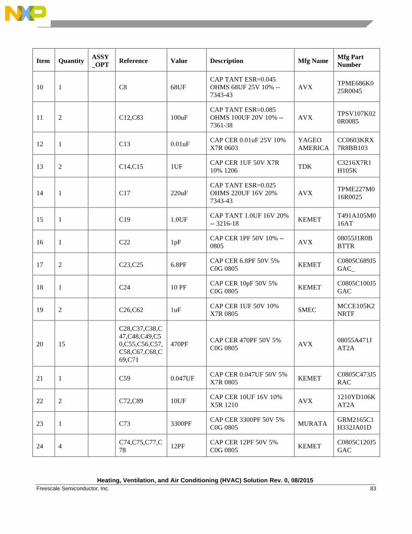
Heating, Ventilation, and Air Conditioning (HVAC) Solution Rev. 0, 08/2015
Freescale Semiconductor, Inc. 83
Item Quantity ASSY
_OPT Reference Value Description Mfg Name
Mfg Part
Number
10 1
C8 68UF
CAP TANT ESR=0.045
OHMS 68UF 25V 10% --
7343-43
AVX TPME686K0
25R0045
11 2
C12,C83 100uF
CAP TANT ESR=0.085
OHMS 100UF 20V 10% --
7361-38
AVX TPSV107K02
0R0085
12 1
C13 0.01uF CAP CER 0.01uF 25V 10%
X7R 0603
YAGEO
AMERICA
CC0603KRX
7R8BB103
13 2
C14,C15 1UF CAP CER 1UF 50V X7R
10% 1206 TDK
C3216X7R1
H105K
14 1
C17 220uF
CAP TANT ESR=0.025
OHMS 220UF 16V 20%
7343-43
AVX TPME227M0
16R0025
15 1
C19 1.0UF CAP TANT 1.0UF 16V 20%
-- 3216-18 KEMET
T491A105M0
16AT
16 1
C22 1pF CAP CER 1PF 50V 10% --
0805 AVX
08055J1R0B
BTTR
17 2
C23,C25 6.8PF CAP CER 6.8PF 50V 5%
C0G 0805 KEMET
C0805C689J5
GAC_
18 1
C24 10 PF CAP CER 10pF 50V 5%
C0G 0805 KEMET
C0805C100J5
GAC
19 2
C26,C62 1uF CAP CER 1UF 50V 10%
X7R 0805 SMEC
MCCE105K2
NRTF
20 15
C28,C37,C38,C
47,C48,C49,C5
0,C55,C56,C57,
C58,C67,C68,C
69,C71
470PF CAP CER 470PF 50V 5%
C0G 0805 AVX
08055A471J
AT2A
21 1
C59 0.047UF CAP CER 0.047UF 50V 5%
X7R 0805 KEMET
C0805C473J5
RAC
22 2
C72,C89 10UF CAP CER 10UF 16V 10%
X5R 1210 AVX
1210YD106K
AT2A
23 1
C73 3300PF CAP CER 3300PF 50V 5%
C0G 0805 MURATA
GRM2165C1
H332JA01D
24 4
C74,C75,C77,C
78 12PF
CAP CER 12PF 50V 5%
C0G 0805 KEMET
C0805C120J5
GAC
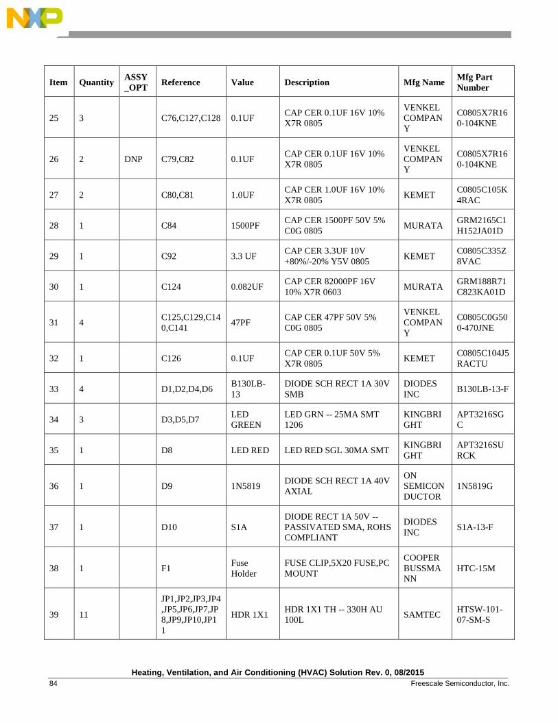
Heating, Ventilation, and Air Conditioning (HVAC) Solution Rev. 0, 08/2015
84 Freescale Semiconductor, Inc.
Item Quantity ASSY
_OPT Reference Value Description Mfg Name
Mfg Part
Number
25 3
C76,C127,C128 0.1UF CAP CER 0.1UF 16V 10%
X7R 0805
VENKEL
COMPAN
Y
C0805X7R16
0-104KNE
26 2 DNP C79,C82 0.1UF CAP CER 0.1UF 16V 10%
X7R 0805
VENKEL
COMPAN
Y
C0805X7R16
0-104KNE
27 2
C80,C81 1.0UF CAP CER 1.0UF 16V 10%
X7R 0805 KEMET
C0805C105K
4RAC
28 1
C84 1500PF CAP CER 1500PF 50V 5%
C0G 0805 MURATA
GRM2165C1
H152JA01D
29 1
C92 3.3 UF CAP CER 3.3UF 10V
+80%/-20% Y5V 0805 KEMET
C0805C335Z
8VAC
30 1
C124 0.082UF CAP CER 82000PF 16V
10% X7R 0603 MURATA
GRM188R71
C823KA01D
31 4
C125,C129,C14
0,C141 47PF
CAP CER 47PF 50V 5%
C0G 0805
VENKEL
COMPAN
Y
C0805C0G50
0-470JNE
32 1
C126 0.1UF CAP CER 0.1UF 50V 5%
X7R 0805 KEMET
C0805C104J5
RACTU
33 4
D1,D2,D4,D6 B130LB-
13
DIODE SCH RECT 1A 30V
SMB
DIODES
INC B130LB-13-F
34 3
D3,D5,D7 LED
GREEN
LED GRN -- 25MA SMT
1206
KINGBRI
GHT
APT3216SG
C
35 1
D8 LED RED LED RED SGL 30MA SMT KINGBRI
GHT
APT3216SU
RCK
36 1
D9 1N5819 DIODE SCH RECT 1A 40V
AXIAL
ON
SEMICON
DUCTOR
1N5819G
37 1
D10 S1A
DIODE RECT 1A 50V --
PASSIVATED SMA, ROHS
COMPLIANT
DIODES
INC S1A-13-F
38 1
F1 Fuse
Holder
FUSE CLIP,5X20 FUSE,PC
MOUNT
COOPER
BUSSMA
NN
HTC-15M
39 11
JP1,JP2,JP3,JP4
,JP5,JP6,JP7,JP
8,JP9,JP10,JP1
1
HDR 1X1 HDR 1X1 TH -- 330H AU
100L SAMTEC
HTSW-101-
07-SM-S
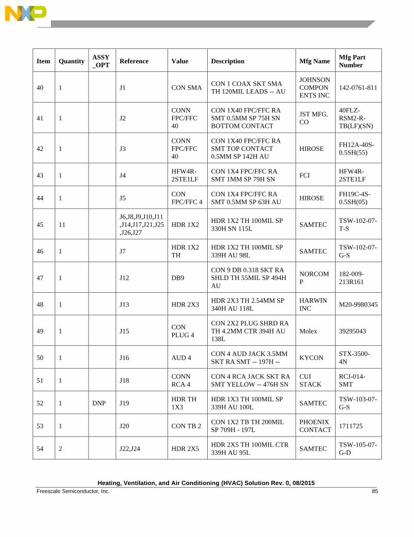
Heating, Ventilation, and Air Conditioning (HVAC) Solution Rev. 0, 08/2015
Freescale Semiconductor, Inc. 85
Item Quantity ASSY
_OPT Reference Value Description Mfg Name
Mfg Part
Number
40 1
J1 CON SMA CON 1 COAX SKT SMA
TH 120MIL LEADS -- AU
JOHNSON
COMPON
ENTS INC
142-0761-811
41 1
J2
CONN
FPC/FFC
40
CON 1X40 FPC/FFC RA
SMT 0.5MM SP 75H SN
BOTTOM CONTACT
JST MFG.
CO
40FLZ-
RSM2-R-
TB(LF)(SN)
42 1
J3
CONN
FPC/FFC
40
CON 1X40 FPC/FFC RA
SMT TOP CONTACT
0.5MM SP 142H AU
HIROSE FH12A-40S-
0.5SH(55)
43 1
J4 HFW4R-
2STE1LF
CON 1X4 FPC/FFC RA
SMT 1MM SP 79H SN FCI
HFW4R-
2STE1LF
44 1
J5 CON
FPC/FFC 4
CON 1X4 FPC/FFC RA
SMT 0.5MM SP 63H AU HIROSE
FH19C-4S-
0.5SH(05)
45 11
J6,J8,J9,J10,J11
,J14,J17,J21,J25
,J26,J27
HDR 1X2 HDR 1X2 TH 100MIL SP
330H SN 115L SAMTEC
TSW-102-07-
T-S
46 1
J7 HDR 1X2
TH
HDR 1X2 TH 100MIL SP
339H AU 98L SAMTEC
TSW-102-07-
G-S
47 1
J12 DB9
CON 9 DB 0.318 SKT RA
SHLD TH 55MIL SP 494H
AU
NORCOM
P
182-009-
213R161
48 1
J13 HDR 2X3 HDR 2X3 TH 2.54MM SP
340H AU 118L
HARWIN
INC M20-9980345
49 1
J15 CON
PLUG 4
CON 2X2 PLUG SHRD RA
TH 4.2MM CTR 394H AU
138L
Molex 39295043
50 1
J16 AUD 4 CON 4 AUD JACK 3.5MM
SKT RA SMT -- 197H -- KYCON
STX-3500-
4N
51 1
J18 CONN
RCA 4
CON 4 RCA JACK SKT RA
SMT YELLOW -- 476H SN
CUI
STACK
RCJ-014-
SMT
52 1 DNP J19 HDR TH
1X3
HDR 1X3 TH 100MIL SP
339H AU 100L SAMTEC
TSW-103-07-
G-S
53 1
J20 CON TB 2 CON 1X2 TB TH 200MIL
SP 709H - 197L
PHOENIX
CONTACT 1711725
54 2
J22,J24 HDR 2X5 HDR 2X5 TH 100MIL CTR
339H AU 95L SAMTEC
TSW-105-07-
G-D
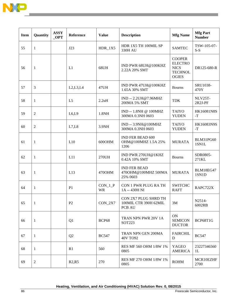
Heating, Ventilation, and Air Conditioning (HVAC) Solution Rev. 0, 08/2015
86 Freescale Semiconductor, Inc.
Item Quantity ASSY
_OPT Reference Value Description Mfg Name
Mfg Part
Number
55 1
J23 HDR_1X5 HDR 1X5 TH 100MIL SP
330H AU SAMTEC
TSW-105-07-
S-S
56 1
L1 68UH IND PWR 68UH@100KHZ
2.22A 20% SMT
COOPER
ELECTRO
NICS
TECHNOL
OGIES
DR125-680-R
57 3
L2,L3,L4 47UH IND PWR 47UH@100KHZ
1.65A 30% SMT Bourns
SRU1038-
470Y
58 1
L5 2.2uH IND -- [email protected]
200MA 5% SMT TDK
NLV25T-
2R2J-PF
59 2
L6,L9 1.8NH IND -- 1.8NH @ 100MHZ
300MA 0.3NH 0603
TAIYO
YUDEN
HK16081N8S
-T
60 2
L7,L8 3.9NH IND -- 3.9NH@100MHZ
300MA 0.3NH 0603
TAIYO
YUDEN
HK16083N9S
-T
61 1
L10 600OHM
IND FER BEAD 600
OHM@100MHZ 1.5A 25%
1206
MURATA BLM31PG60
1SN1L
62 1
L11 270UH IND PWR 270UH@1KHZ
0.42A 10% SMT Bourns
SDR0805-
271KL
63 1
L13 470OHM
IND FER BEAD
470OHM@100MHZ 500MA
25% 0603
MURATA BLM18EG47
1SN1D
64 1
P1 CON_1_P
WR
CON 1 PWR PLUG RA TH
1A -- 430H NI
SWITCHC
RAFT RAPC722X
65 1
P2 CON_2X7
CON 2X7 PLUG SHRD TH
100MIL CTR 390H 62MIL
PCB AU
3M N2514-
6002RB
66 1
Q1 BCP68 TRAN NPN PWR 20V 1A
SOT223
ON
SEMICON
DUCTOR
BCP68T1G
67 1
Q2 BC547 TRAN NPN GEN 200MA
40V TO92
FAIRCHIL
D BC547
68 1
R1 560 RES MF 560 OHM 1/8W 1%
0805
YAGEO
AMERICA
23227346560
1L
69 2
R2,R5 270 RES MF 270 OHM 1/8W 1%
0805 ROHM
MCR10EZHF
2700
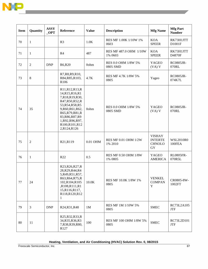
Heating, Ventilation, and Air Conditioning (HVAC) Solution Rev. 0, 08/2015
Freescale Semiconductor, Inc. 87
Item Quantity ASSY
_OPT Reference Value Description Mfg Name
Mfg Part
Number
70 1
R3 1.0K RES MF 1.00K 1/10W 1%
0603
KOA
SPEER
RK73H1JTT
D1001F
71 1
R4 487 RES MF 487.0 OHM 1/10W
1% 0603
KOA
SPEER
RK73H1JTT
D4870F
72 2 DNP R6,R20 0ohm RES 0.0 OHM 1/8W 5%
0805 SMD
YAGEO
(VA) V
RC0805JR-
070RL
73 8
R7,R8,R9,R10,
R84,R85,R103,
R106
4.7K RES MF 4.7K 1/8W 5%
0805 Yageo
RC0805JR-
074K7L
74 35
R11,R12,R13,R
14,R15,R16,R1
7,R18,R19,R30,
R47,R50,R52,R
53,R54,R58,R5
9,R60,R61,R62,
R65,R79,R81,R
83,R86,R87,R9
1,R92,R96,R97,
R100,R101,R12
2,R124,R126
0ohm RES 0.0 OHM 1/8W 5%
0805 SMD
YAGEO
(VA) V
RC0805JR-
070RL
75 2
R21,R119 0.01 OHM RES MF 0.01 OHM 1/2W
1% 2010
VISHAY
INTERTE
CHNOLO
GY
WSL2010R0
100FEA
76 1
R22 0.5 RES MF 0.50 OHM 1/8W
1% 0805
YAGEO
AMERICA
RL0805FR-
070R5L
77 24
R23,R26,R27,R
28,R29,R44,R4
5,R49,R51,R57,
R63,R64,R75,R
102,R104,R105
,R108,R111,R1
15,R116,R117,
R118,R120,R12
1
10.0K RES MF 10.0K 1/8W 1%
0805
VENKEL
COMPAN
Y
CR0805-8W-
1002FT
79 3 DNP R24,R31,R48 1M RES MF 1M 1/10W 5%
0805 SMEC
RC73L2A105
JTF
80 11
R25,R32,R33,R
34,R35,R36,R3
7,R38,R39,R80,
R127
100 RES MF 100 OHM 1/8W 5%
0805 SMEC
RC73L2D101
JTF
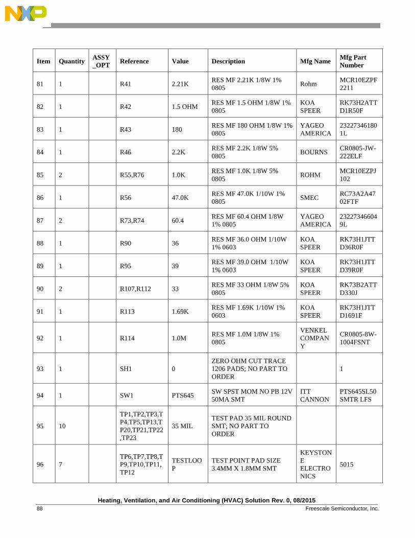
Heating, Ventilation, and Air Conditioning (HVAC) Solution Rev. 0, 08/2015
88 Freescale Semiconductor, Inc.
Item Quantity ASSY
_OPT Reference Value Description Mfg Name
Mfg Part
Number
81 1
R41 2.21K RES MF 2.21K 1/8W 1%
0805 Rohm
MCR10EZPF
2211
82 1
R42 1.5 OHM RES MF 1.5 OHM 1/8W 1%
0805
KOA
SPEER
RK73H2ATT
D1R50F
83 1
R43 180 RES MF 180 OHM 1/8W 1%
0805
YAGEO
AMERICA
23227346180
1L
84 1
R46 2.2K RES MF 2.2K 1/8W 5%
0805 BOURNS
CR0805-JW-
222ELF
85 2
R55,R76 1.0K RES MF 1.0K 1/8W 5%
0805 ROHM
MCR10EZPJ
102
86 1
R56 47.0K RES MF 47.0K 1/10W 1%
0805 SMEC
RC73A2A47
02FTF
87 2
R73,R74 60.4 RES MF 60.4 OHM 1/8W
1% 0805
YAGEO
AMERICA
23227346604
9L
88 1
R90 36 RES MF 36.0 OHM 1/10W
1% 0603
KOA
SPEER
RK73H1JTT
D36R0F
89 1
R95 39 RES MF 39.0 OHM 1/10W
1% 0603
KOA
SPEER
RK73H1JTT
D39R0F
90 2
R107,R112 33 RES MF 33 OHM 1/8W 5%
0805
KOA
SPEER
RK73B2ATT
D330J
91 1
R113 1.69K RES MF 1.69K 1/10W 1%
0603
KOA
SPEER
RK73H1JTT
D1691F
92 1
R114 1.0M RES MF 1.0M 1/8W 1%
0805
VENKEL
COMPAN
Y
CR0805-8W-
1004FSNT
93 1
SH1 0
ZERO OHM CUT TRACE
1206 PADS; NO PART TO
ORDER 1
94 1
SW1 PTS645 SW SPST MOM NO PB 12V
50MA SMT
ITT
CANNON
PTS645SL50
SMTR LFS
95 10
TP1,TP2,TP3,T
P4,TP5,TP13,T
P20,TP21,TP22
,TP23
35 MIL
TEST PAD 35 MIL ROUND
SMT; NO PART TO
ORDER
96 7
TP6,TP7,TP8,T
P9,TP10,TP11,
TP12
TESTLOO
P
TEST POINT PAD SIZE
3.4MM X 1.8MM SMT
KEYSTON
E
ELECTRO
NICS
5015
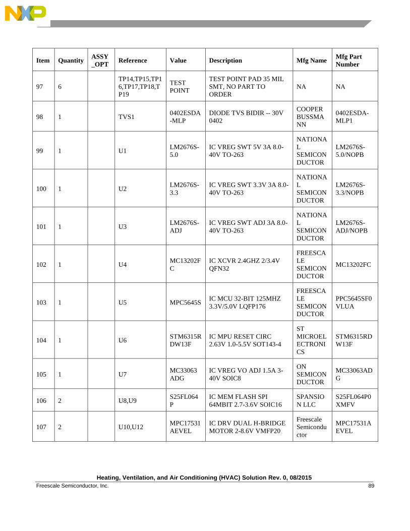
Heating, Ventilation, and Air Conditioning (HVAC) Solution Rev. 0, 08/2015
Freescale Semiconductor, Inc. 89
Item Quantity ASSY
_OPT Reference Value Description Mfg Name
Mfg Part
Number
97 6
TP14,TP15,TP1
6,TP17,TP18,T
P19
TEST
POINT
TEST POINT PAD 35 MIL
SMT, NO PART TO
ORDER
NA NA
98 1
TVS1 0402ESDA
-MLP
DIODE TVS BIDIR -- 30V
0402
COOPER
BUSSMA
NN
0402ESDA-
MLP1
99 1
U1 LM2676S-
5.0
IC VREG SWT 5V 3A 8.0-
40V TO-263
NATIONA
L
SEMICON
DUCTOR
LM2676S-
5.0/NOPB
100 1
U2 LM2676S-
3.3
IC VREG SWT 3.3V 3A 8.0-
40V TO-263
NATIONA
L
SEMICON
DUCTOR
LM2676S-
3.3/NOPB
101 1
U3 LM2676S-
ADJ
IC VREG SWT ADJ 3A 8.0-
40V TO-263
NATIONA
L
SEMICON
DUCTOR
LM2676S-
ADJ/NOPB
102 1
U4 MC13202F
C
IC XCVR 2.4GHZ 2/3.4V
QFN32
FREESCA
LE
SEMICON
DUCTOR
MC13202FC
103 1
U5 MPC5645S IC MCU 32-BIT 125MHZ
3.3V/5.0V LQFP176
FREESCA
LE
SEMICON
DUCTOR
PPC5645SF0
VLUA
104 1
U6 STM6315R
DW13F
IC MPU RESET CIRC
2.63V 1.0-5.5V SOT143-4
ST
MICROEL
ECTRONI
CS
STM6315RD
W13F
105 1
U7 MC33063
ADG
IC VREG VO ADJ 1.5A 3-
40V SOIC8
ON
SEMICON
DUCTOR
MC33063AD
G
106 2
U8,U9 S25FL064
P
IC MEM FLASH SPI
64MBIT 2.7-3.6V SOIC16
SPANSIO
N LLC
S25FL064P0
XMFV
107 2
U10,U12 MPC17531
AEVEL
IC DRV DUAL H-BRIDGE
MOTOR 2-8.6V VMFP20
Freescale
Semicondu
ctor
MPC17531A
EVEL
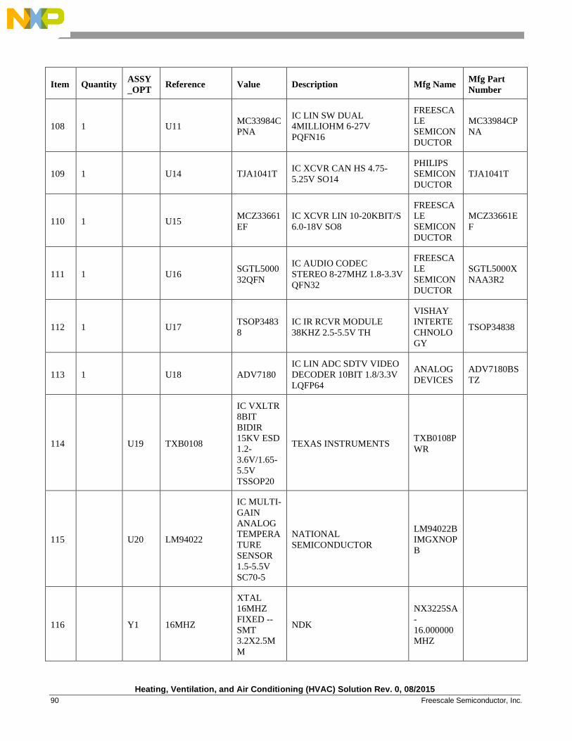
Heating, Ventilation, and Air Conditioning (HVAC) Solution Rev. 0, 08/2015
90 Freescale Semiconductor, Inc.
Item Quantity ASSY
_OPT Reference Value Description Mfg Name
Mfg Part
Number
108 1
U11 MC33984C
PNA
IC LIN SW DUAL
4MILLIOHM 6-27V
PQFN16
FREESCA
LE
SEMICON
DUCTOR
MC33984CP
NA
109 1
U14 TJA1041T IC XCVR CAN HS 4.75-
5.25V SO14
PHILIPS
SEMICON
DUCTOR
TJA1041T
110 1
U15 MCZ33661
EF
IC XCVR LIN 10-20KBIT/S
6.0-18V SO8
FREESCA
LE
SEMICON
DUCTOR
MCZ33661E
F
111 1
U16 SGTL5000
32QFN
IC AUDIO CODEC
STEREO 8-27MHZ 1.8-3.3V
QFN32
FREESCA
LE
SEMICON
DUCTOR
SGTL5000X
NAA3R2
112 1
U17 TSOP3483
8
IC IR RCVR MODULE
38KHZ 2.5-5.5V TH
VISHAY
INTERTE
CHNOLO
GY
TSOP34838
113 1
U18 ADV7180
IC LIN ADC SDTV VIDEO
DECODER 10BIT 1.8/3.3V
LQFP64
ANALOG
DEVICES
ADV7180BS
TZ
114
U19 TXB0108
IC VXLTR
8BIT
BIDIR
15KV ESD
1.2-
3.6V/1.65-
5.5V
TSSOP20
TEXAS INSTRUMENTS TXB0108P
WR
115
U20 LM94022
IC MULTI-
GAIN
ANALOG
TEMPERA
TURE
SENSOR
1.5-5.5V
SC70-5
NATIONAL
SEMICONDUCTOR
LM94022B
IMGXNOP
B
116
Y1 16MHZ
XTAL
16MHZ
FIXED --
SMT
3.2X2.5M
M
NDK
NX3225SA
-
16.000000
MHZ
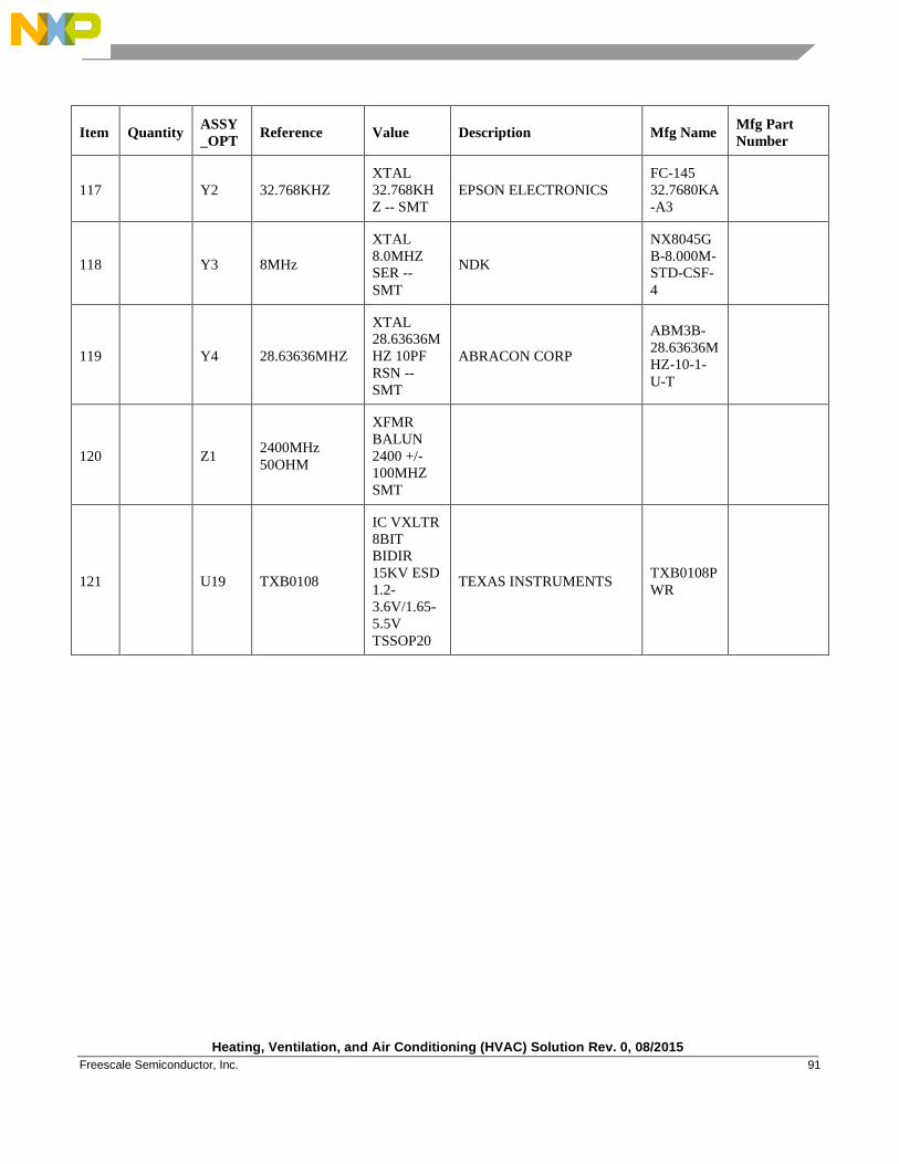
Heating, Ventilation, and Air Conditioning (HVAC) Solution Rev. 0, 08/2015
Freescale Semiconductor, Inc. 91
Item Quantity ASSY
_OPT Reference Value Description Mfg Name
Mfg Part
Number
117
Y2 32.768KHZ
XTAL
32.768KH
Z -- SMT
EPSON ELECTRONICS
FC-145
32.7680KA
-A3
118
Y3 8MHz
XTAL
8.0MHZ
SER --
SMT
NDK
NX8045G
B-8.000M-
STD-CSF-
4
119
Y4 28.63636MHZ
XTAL
28.63636M
HZ 10PF
RSN --
SMT
ABRACON CORP
ABM3B-
28.63636M
HZ-10-1-
U-T
120
Z1 2400MHz
50OHM
XFMR
BALUN
2400 +/-
100MHZ
SMT
121
U19 TXB0108
IC VXLTR
8BIT
BIDIR
15KV ESD
1.2-
3.6V/1.65-
5.5V
TSSOP20
TEXAS INSTRUMENTS TXB0108P
WR

Document Number: DRM166 Rev. 0
08/2015
How to Reach Us:
Home Page:
freescale.com
Web Support:
freescale.com/support
Information in this document is provided solely to enable system and software implementers to
use Freescale products. There are no express or implied copyright licenses granted hereunder to
design or fabricate any integrated circuits based on the information in this document.
Freescale reserves the right to make changes without further notice to any products herein.
Freescale makes no warranty, representation, or guarantee regarding the suitability of its
products for any particular purpose, nor does Freescale assume any liability arising out of the
application or use of any product or circuit, and specifically disclaims any and all liability,
including without limitation consequential or incidental damages. “Typical” parameters that may
be provided in Freescale data sheets and/or specifications can and do vary in different
applications, and actual performance may vary over time. All operating parameters, including
“typicals,” must be validated for each customer application by customer's technical experts.
Freescale does not convey any license under its patent rights nor the rights of others. Freescale
sells products pursuant to standard terms and conditions of sale, which can be found at the
following address: freescale.com/SalesTermsandConditions.
Freescale and the Freescale logo are trademarks of Freescale Semiconductor,Inc., Reg. U.S. Pat.
& Tm. Off. All other product or service names are the property of their respective owners.
© 2015 Freescale Semiconductor, Inc.