hvac duct construction standards - techstreet
TRANSCRIPT


HVACDUCT CONSTRUCTION
STANDARDSMETAL AND FLEXIBLE
THIRD EDITION − 2005
SHEET METAL AND AIR CONDITIONING CONTRACTORS’NATIONAL ASSOCIATION, INC.
4201 Lafayette Center DriveChantilly, VA 20151−1209
www.smacna.org
HVACDUCT CONSTRUCTION
STANDARDSMETAL AND FLEXIBLE
COPYRIGHT � SMACNA 2005All Rights Reserved
by
SHEET METAL AND AIR CONDITIONING CONTRACTORS’NATIONAL ASSOCIATION, INC.
4201 Lafayette Center DriveChantilly, VA 20151−1209
Printed in the U.S.A.
FIRST EDITION − 1985SECOND EDITION − 1995
THIRD EDITION − 2005SECOND PRINTING − 2006
THIRD PRINTING − 2008FOURTH PRINTING − 2009
Except as allowed in the Notice to Users and in certain licensing contracts, no part of this book may bereproduced, stored in a retrievable system, or transmitted, in any form or by any means, electronic,
mechanical, photocopying, recording, or otherwise, without the prior written permission of the publisher.

iiiHVAC Duct Construction Standards Metal and Flexible • Third Edition
FOREWORD
This Third Edition of the SMACNA commercial metal and flexible duct construction standards is another in a long
line dating from the 1950s. A quick overview of the changes is provided in the front of this manual.
SMACNA expresses appreciation to the many who have offered suggestions for constructive improvement in the fab-
rication and installation of duct systems. Suggestions for future improvement are welcome. Special thanks is given
to those who volunteered their time, gave special knowledge and struggled with development of a consensus that
would reflect the needs for a diversified industry. Although standardization intrinsically involves selection, no inten-
tion of discrimination against the use of any product or method that would serve a designer’s need equally or better
exists.
SHEET METAL AND AIR CONDITIONING CONTRACTORS’
NATIONAL ASSOCIATION, INC.

iv HVAC Duct Construction Standards Metal and Flexible • Third Edition
HVAC DUCT CONSTRUCTION TASK FORCE
Roy Jensen, Chairman
MechOne
Colorado Springs, Colorado
Douglas Ahlberg
Arctic Sheet Metal, Inc.
Portland, Oregon
Chris Combe
Superior Air Handling Corporation
Clearfield, Utah
Mark Edhammer
Southland Industries
San Jose, California
Roy Ricci
McCusker−Gill, Inc.
Hingham, Massachusetts
Jerry Robinson
Stromberg Sheet Metal Works, Inc.
Beltsville, Maryland
Robert J. Wasilewski, Staff Liaison
SMACNA, Inc.
Chantilly, Virginia
Eli P. Howard, III, Staff Liaison
SMACNA, Inc.
Chantilly, Virginia
FORMER COMMITTEE MEMBERS* ANDOTHER CONTRIBUTORS TO THE THIRD EDITION
Michael Mamayek*, Chairman 1992 − 1993
Illingworth Corporation
Milwaukee, WI
Thomas Boniface*, Chairman 1989 − 1991
Independent Sheet Metal
Wayne, NJ
H. Andrew Kimmel*, Chairman 1988
E.W. Ensroth Co.
Warren, MI
Robert S. Deeds*, Chairman 1986 − 1987
METCO, Inc.
Salt Lake City, UT
Norman T.R. Heathorn*
N.B. Heathorn, Inc.
Oakland, CA
Gerald D. Hermanson*
Hermanson Corporation
Renton, WA
George J. Thomas, Jr.*
Thomas Roofing & Sheet Metal Co., Inc.
Atlantic City, NJ
Guillermo (�Bill") Navas, Staff
SMACNA
Chantilly, VA
Ronald Rodgers, Chairman
J.B. Rodgers Mechanical Contractors
Phoenix, AZ
Seymore Cohen
Knecht, Inc.
Camden, NJ
Dick Hoffa
Corn States Metal Fabricators, Inc.
West Des Moine, IA
Ronald Palmerick
AABCO Sheet Metal
Brooklyn, NY
Les Santeler
Climatemp, Inc.
Chicago, IL
John H. Stratton, Staff
SMACNA
Chantilly, VA

v HVAC Duct Construction Standards Metal and Flexible • Third Edition
NOTICE TO USERSOF THIS PUBLICATION
1. DISCLAIMER OF WARRANTIES
a) The Sheet Metal and Air Conditioning Contractors’ National Association (�SMACNA") provides its product for informationalpurposes.
b) The product contains �Data" which is believed by SMACNA to be accurate and correct but the data, including all information,ideas and expressions therein, is provided strictly �AS IS," with all faults. SMACNA makes no warranty either express or impliedregarding the Data and SMACNA EXPRESSLY DISCLAIMS ANY IMPLIED WARRANTIES OF MERCHANTABILITY ORFITNESS FOR PARTICULAR PURPOSE.
c) By using the data contained in the product user accepts the Data �AS IS" and assumes all risk of loss, harm or injury that may resultfrom its use. User acknowledges that the Data is complex, subject to faults and requires verification by competent professionals, andthat modification of parts of the Data by user may impact the results or other parts of the Data.
d) IN NO EVENT SHALL SMACNA BE LIABLE TO USER, OR ANY OTHER PERSON, FOR ANY INDIRECT, SPECIAL ORCONSEQUENTIAL DAMAGES ARISING, DIRECTLY OR INDIRECTLY, OUT OF OR RELATED TO USER’S USE OFSMACNA’S PRODUCT OR MODIFICATION OF DATA THEREIN. This limitation of liability applies even if SMACNA has beenadvised of the possibility of such damages. IN NO EVENT SHALL SMACNA’S LIABILITY EXCEED THE AMOUNT PAID BYUSER FOR ACCESS TO SMACNA’S PRODUCT OR $1,000.00, WHICHEVER IS GREATER, REGARDLESS OF LEGALTHEORY.
e) User by its use of SMACNA’s product acknowledges and accepts the foregoing limitation of liability and disclaimer of warrantyand agrees to indemnify and hold harmless SMACNA from and against all injuries, claims, loss or damage arising, directly or indi-rectly, out of user’s access to or use of SMACNA’s product or the Data contained therein.
2. ACCEPTANCE
This document or publication is prepared for voluntary acceptance and use within the limitations of application defined herein, andotherwise as those adopting it or applying it deem appropriate. It is not a safety standard. Its application for a specific project is contin-gent on a designer or other authority defining a specific use. SMACNA has no power or authority to police or enforce compliance withthe contents of this document or publication and it has no role in any representations by other parties that specific components are, infact, in compliance with it.
3. AMENDMENTS
The Association may, from time to time, issue formal interpretations or interim amendments, which can be of significance betweensuccessive editions.
4. PROPRIETARY PRODUCTS
SMACNA encourages technological development in the interest of improving the industry for the public benefit. SMACNA does not,however, endorse individual manufacturers or products.
5. FORMAL INTERPRETATION
a) A formal interpretation of the literal text herein or the intent of the technical committee or task force associated with the documentor publication is obtainable only on the basis of written petition, addressed to the Technical Resources Department and sent to theAssociation’s national office in Chantilly, Virginia. In the event that the petitioner has a substantive disagreement with the interpreta-tion, an appeal may be filed with the Technical Resources Committee, which has technical oversight responsibility. The request mustpertain to a specifically identified portion of the document that does not involve published text which provides the requested informa-tion. In considering such requests, the Association will not review or judge products or components as being in compliance with thedocument or publication. Oral and written interpretations otherwise obtained from anyone affiliated with the Association are unoffi-cial. This procedure does not prevent any committee or task force chairman, member of the committee or task force, or staff liaisonfrom expressing an opinion on a provision within the document, provided that such person clearly states that the opinion is personaland does not represent an official act of the Association in any way, and it should not be relied on as such. The Board of Directors ofSMACNA shall have final authority for interpretation of this standard with such rules or procedures as they may adopt for processingsame.
b) SMACNA disclaims any liability for any personal injury, property damage, or other damage of any nature whatsoever, whetherspecial, indirect, consequential or compensatory, direct or indirectly resulting from the publication, use of, or reliance upon this docu-ment. SMACNA makes no guaranty or warranty as to the accuracy or completeness of any information published herein.
6. APPLICATION
a) Any standards contained in this publication were developed using reliable engineering principles and research plus consultationwith, and information obtained from, manufacturers, users, testing laboratories, and others having specialized experience. They are
vi HVAC Duct Construction Standards Metal and Flexible • Third Edition
subject to revision as further experience and investigation may show is necessary or desirable. Construction and products which com-ply with these Standards will not necessarily be acceptable if, when examined and tested, they are found to have other features whichimpair the result contemplated by these requirements. The Sheet Metal and Air Conditioning Contractors’ National Association andother contributors assume no responsibility and accept no liability for the application of the principles or techniques contained in thispublication. Authorities considering adoption of any standards contained herein should review all federal, state, local, and contractregulations applicable to specific installations.
b) In issuing and making this document available, SMACNA is not undertaking to render professional or other services for or onbehalf of any person or entity. SMACNA is not undertaking to perform any duty owed to any person or entity to someone else. Anyperson or organization using this document should rely on his, her or its own judgement or, as appropriate, seek the advice of a compe-tent professional in determining the exercise of reasonable care in any given circumstance.
7. REPRINT PERMISSION
Non−exclusive, royalty−free permission is granted to government and private sector specifying authorities to reproduce only anyconstruction details found herein in their specifications and contract drawings prepared for receipt of bids on new construction andrenovation work within the United States and its territories, provided that the material copied is unaltered in substance and that thereproducer assumes all liability for the specific application, including errors in reproduction.
8. THE SMACNA LOGO
The SMACNA logo is registered as a membership identification mark. The Association prescribes acceptable use of the logo andexpressly forbids the use of it to represent anything other than possession of membership. Possession of membership and use of thelogo in no way constitutes or reflects SMACNA approval of any product, method, or component. Furthermore, compliance of anysuch item with standards published or recognized by SMACNA is not indicated by presence of the logo.

MODEL PROJECT SPECIFICATION
HVAC Duct Construction Standards Metal and Flexible • Third Edition vii
DUCT CONSTRUCTION
Ductwork and supports shall conform to the HVAC
Duct Construction Standards, Metal and Flexible,
Third Edition, 2005. Where fittings of configurations
not shown in the HVAC−DCS are shown on the contract
drawings, they shall be constructed as though they were
therein.
DUCT DIMENSIONS
Duct dimensions shown in the contract drawings are for
airflow area. When ducts are acoustically lined, their
dimensions shall be increased as necessary.
DUCT PRESSURE CLASS
Duct pressure classes are to be identified on the contract
drawings.
*Schedule the pressure classes here by fan system num-
ber, or portion thereof, if they are not shown on the
drawings.
See Section 1.4.
DUCT SEAL CLASS
Ducts shall be sealed as specified in the HVAC−DCS.
DUCT LEAKAGE CLASS
*Consult the HVAC−Air Duct Leakage Test Manual and
select appropriate allowable leakage. If field leak tests
are required, appropriate test pressure and clear scope
of testing must be specified.
DUCT LINER
Metal nosing shall be used on leading edges of each
piece of lined duct when the velocity exceeds 4000 fpm
(20.3 m/s) otherwise, it shall be used on the leading
edge of any lined duct section that is preceded by un-
lined duct.
*See duct liner test and references in the HVAC−DCS
and specify the material, thickness, density and perfor-
mance characteristics desired.
FLEXIBLE DUCT AND CONNECTOR
Where the specifications for connecting and supporting
these in the HVAC−DCS are more stringent or restric-
tive, they shall supersede.
VIBRATION ISOLATION CONNECTORS
Flexible isolation connectors shall not exceed 10 in. in
length in direction of airflow and shall be made of
flame−retardant fabric having a flame spread rating not
over 25 and a smoke developed rating not over 50.
*Consult the applicable codes, The U.L. Fire Resist-
ance Directory, references in the HVAC−DCS, the Air
Diffusion Council’s Flexible Air Duct Performance
and Installation Standards and identify the products
and performance characteristics desired.
PROPRIETARY PRODUCTS
Description of products from a proprietary or single
source manufacturer shall be submitted for approval
along with substantiation of fitness for the service con-
ditions that are proposed but not already identified in
the project specifications.
PENETRATIONS
All wall penetrations that require special−purpose
dampers (fire, smoke, etc.) shall be shown in the con-
tract drawings.
*Consult the SMACNA Fire, Smoke, and Radiation
Damper Guide and local codes for obligations to show
the location of each barrier penetration protection de-
vice on contract drawing. Review the commentary in
Section 2.3 of these standards for obligation to show all
air volume control devices on the contract drawings
when they are not specified to be integral with HVAC
units or air terminal units. Also specify the size and
location of all access doors and access panels to be
used in ductwork.
*NOTES FOR SPECIFIER

HVAC Duct Construction Standards Metal and Flexible • Third Editionviii
LIST OF MAJOR CHANGES FROM THE SECOND EDITION
1. Added Engineering and Design chapter.
2. Added Double Wall construction details.
3. Added New Casing construction details.
4. Included the use of Framing Channel (strut) for use
as trapeze supports and duct reinforcement.
5. Narrowscope tables eliminated.
KEY RECTANGULAR DUCT CONSTRUCTIONREVISIONS
1. Pressure class tables expanded to include selec-
tions previously not designed.
2. Figures added highlighting the conditions of use
and limitations for transverse joints, longitudinal
seam and reinforcements.
3. Added detailed tables for joints T−25a and T−25b
for 4, 5, and 6 ft (1.20, 1.50 and 1.80 mm) stock –
coil or sheet.
4. Mid panel tie rod application expanded to include
6 in. wg (1500 Pa) negative pressure and additional
panel sizes.
5. Table given for large duct construction [(over 120
in. (3000 mm)].
KEY ROUND AND OVAL DUCT REVISIONS
1. Round construction given to 96 in. (2400 mm) di-
ameter.
2. 6 in. wg (1500 Pa) pressure class added.
3. Detailed tables given for longitudinal and spiral
seam ducts for reinforcement spacings of 20, 12,
10, 6, 5 ft (6.00, 3.60, 3.00, 1.80, 1.50 mm) plus un-
stiffened duct.
4. Added minimum gage table for flat oval duct.

TABLE OF CONTENTS


TABLE OF CONTENTS
ixHVAC Duct Construction Standards Metal and Flexible • Third Edition
FOREWORD iii. . . . . . . . . . . . . . . . . . . . . . . . . . . . . . . . . . . . . . . . . . . . . . . . . . . . . . . . . . . . . . . . . . . . . . . . . . . . . .
HVAC DUCT CONSTRUCTION TASK FORCE iv. . . . . . . . . . . . . . . . . . . . . . . . . . . . . . . . . . . . . . . . . . . . . . . .
NOTICE TO USERS OF THIS PUBLICATION v. . . . . . . . . . . . . . . . . . . . . . . . . . . . . . . . . . . . . . . . . . . . . . . . .
MODEL PROJECT SPECIFICATION vii. . . . . . . . . . . . . . . . . . . . . . . . . . . . . . . . . . . . . . . . . . . . . . . . . . . . . . . .
LIST OF MAJOR CHANGES FROM THE SECOND EDITION viii. . . . . . . . . . . . . . . . . . . . . . . . . . . . . . . . .
TABLE OF CONTENTS ix. . . . . . . . . . . . . . . . . . . . . . . . . . . . . . . . . . . . . . . . . . . . . . . . . . . . . . . . . . . . . . . . . . . . .
CHAPTER 1 ENGINEERING AND DESIGN Page
1.1 INTRODUCTION 1.1. . . . . . . . . . . . . . . . . . . . . . . . . . . . . . . . . . . . . . . . . . . . . . . . . . . . . . . . 1.2 INFORMATION REQUIRED FOR DUCT CONSTRUCTION 1.1 . . . . . . . . . . . . . . . . . . . 1.3 MODEL SPECIFICATIONS 1.1 . . . . . . . . . . . . . . . . . . . . . . . . . . . . . . . . . . . . . . . . . . . . . . . 1.4 DUCT SEALING 1.11. . . . . . . . . . . . . . . . . . . . . . . . . . . . . . . . . . . . . . . . . . . . . . . . . . . . . . . . . 1.5 INTRODUCTION TO BASIC CONSTRUCTION 1.13. . . . . . . . . . . . . . . . . . . . . . . . . . . . . . 1.6 DEPENDENT VARIABLES 1.18. . . . . . . . . . . . . . . . . . . . . . . . . . . . . . . . . . . . . . . . . . . . . . . .
CHAPTER 2 RECTANGULAR DUCT CONSTRUCTION
2.1 INTRODUCTION TO THE RECTANGULAR DUCT CONSTRUCTIONSCHEDULES 2.1 . . . . . . . . . . . . . . . . . . . . . . . . . . . . . . . . . . . . . . . . . . . . . . . . . . . . . . . . . . . .
2.2 RECTANGULAR DUCT REINFORCEMENT 2.4 . . . . . . . . . . . . . . . . . . . . . . . . . . . . . . . . . 2.3 LONGITUDINAL SEAMS FOR RECTANGULAR DUCT 2.11. . . . . . . . . . . . . . . . . . . . . . . 2.4 TRANSVERSE JOINTS FOR RECTANGULAR DUCT 2.73. . . . . . . . . . . . . . . . . . . . . . . . 2.5 TIE ROD INSTALLATIONS 2.80. . . . . . . . . . . . . . . . . . . . . . . . . . . . . . . . . . . . . . . . . . . . . . . . 2.6 COMMENTARY 2.81. . . . . . . . . . . . . . . . . . . . . . . . . . . . . . . . . . . . . . . . . . . . . . . . . . . . . . . . . 2.7 MIDPANEL TIE ROD APPLICATIONS 2.97. . . . . . . . . . . . . . . . . . . . . . . . . . . . . . . . . . . . . . 2.8 MIDPANEL TIE ROD (MPT) USE GUIDE 2.97. . . . . . . . . . . . . . . . . . . . . . . . . . . . . . . . . . . 2.9 MIDPANEL TIE ROD SELECTIONS 2.98. . . . . . . . . . . . . . . . . . . . . . . . . . . . . . . . . . . . . . . . 2.10 COMMENTARY ON ALUMINUM DUCT 2.123. . . . . . . . . . . . . . . . . . . . . . . . . . . . . . . . . . . . .
CHAPTER 3 ROUND, OVAL AND FLEXIBLE DUCT
3.1 ROUND DUCT CONSTRUCTION STANDARDS 3.1 . . . . . . . . . . . . . . . . . . . . . . . . . . . . . 3.2 COMMENTARY 3.2 . . . . . . . . . . . . . . . . . . . . . . . . . . . . . . . . . . . . . . . . . . . . . . . . . . . . . . . . . 3.3 FLAT OVAL DUCT CONSTRUCTION STANDARDS 3.27 . . . . . . . . . . . . . . . . . . . . . . . . . . 3.4 COMMENTARY 3.27 . . . . . . . . . . . . . . . . . . . . . . . . . . . . . . . . . . . . . . . . . . . . . . . . . . . . . . . . . 3.5 FLEXIBLE DUCT INSTALLATION STANDARDS 3.33 . . . . . . . . . . . . . . . . . . . . . . . . . . . . . 3.6 SPECIFICATION FOR JOINING AND ATTACHING FLEXIBLE DUCT 3.33 . . . . . . . . . . 3.7 SPECIFICATION FOR SUPPORTING FLEXIBLE DUCT 3.33 . . . . . . . . . . . . . . . . . . . . . . 3.8 COMMENTARY 3.39 . . . . . . . . . . . . . . . . . . . . . . . . . . . . . . . . . . . . . . . . . . . . . . . . . . . . . . . . .
CHAPTER 4 FITTINGS AND OTHER CONSTRUCTION
4.1 REQUIREMENTS 4.1 . . . . . . . . . . . . . . . . . . . . . . . . . . . . . . . . . . . . . . . . . . . . . . . . . . . . . . . .
CHAPTER 5 HANGERS AND SUPPORTS
5.1 HANGING AND SUPPORTING SYSTEMS 5.1 . . . . . . . . . . . . . . . . . . . . . . . . . . . . . . . . . . 5.2 COMMENTARY 5.1 . . . . . . . . . . . . . . . . . . . . . . . . . . . . . . . . . . . . . . . . . . . . . . . . . . . . . . . . .

x HVAC Duct Construction Standards Metal and Flexible • Third Edition
CHAPTER 6 EXTERIOR COMPONENTS Page
6.1 INTRODUCTION 6.1 . . . . . . . . . . . . . . . . . . . . . . . . . . . . . . . . . . . . . . . . . . . . . . . . . . . . . . . . 6.2 ROOFTOP EQUIPMENT INSTALLATION 6.5 . . . . . . . . . . . . . . . . . . . . . . . . . . . . . . . . . . . 6.3 COMMENTARY 6.5 . . . . . . . . . . . . . . . . . . . . . . . . . . . . . . . . . . . . . . . . . . . . . . . . . . . . . . . . .
CHAPTER 7 ACCESSORIES
7.1 VOLUME DAMPERS 7.5 . . . . . . . . . . . . . . . . . . . . . . . . . . . . . . . . . . . . . . . . . . . . . . . . . . . . . 7.2 NOTES FOR FIGURES 7−4 AND 7−5 7.5 . . . . . . . . . . . . . . . . . . . . . . . . . . . . . . . . . . . . . . 7.3 COMMENTARY 7.5 . . . . . . . . . . . . . . . . . . . . . . . . . . . . . . . . . . . . . . . . . . . . . . . . . . . . . . . . . 7.4 INSTALLATION STANDARDS FOR RECTANGULAR DUCTS
USING FLEXIBLE LINER 7.14 . . . . . . . . . . . . . . . . . . . . . . . . . . . . . . . . . . . . . . . . . . . . . . . . . 7.5 COMMENTARY 7.15 . . . . . . . . . . . . . . . . . . . . . . . . . . . . . . . . . . . . . . . . . . . . . . . . . . . . . . . . .
CHAPTER 8 DOUBLE−WALL DUCT CONSTRUCTION
8.1 INSTALLATION STANDARDS COMMENTARY 8.1 . . . . . . . . . . . . . . . . . . . . . . . . . . . . . .
CHAPTER 9 EQUIPMENT AND CASINGS
9.1 CASING AND PLENUM CONSTRUCTION STANDARDS 9.1 . . . . . . . . . . . . . . . . . . . . . 9.2 COMMENTARY 9.24 . . . . . . . . . . . . . . . . . . . . . . . . . . . . . . . . . . . . . . . . . . . . . . . . . . . . . . . . . 9.3 CASING ARRANGEMENT 9.24 . . . . . . . . . . . . . . . . . . . . . . . . . . . . . . . . . . . . . . . . . . . . . . . .
CHAPTER 10 SPECIALTY SYSTEMS
10.1 HOODS 10.2 . . . . . . . . . . . . . . . . . . . . . . . . . . . . . . . . . . . . . . . . . . . . . . . . . . . . . . . . . . . . . . . 10.2 UNDERGROUND DUCT CONSTRUCTION STANDARDS 10.4 . . . . . . . . . . . . . . . . . . . 10.3 COMMENTARY 10.7 . . . . . . . . . . . . . . . . . . . . . . . . . . . . . . . . . . . . . . . . . . . . . . . . . . . . . . . .
CHAPTER 11 FUNCTIONAL CRITERIA
11.1 FUNCTIONAL CRITERIA FOR DUCTS 11.1 . . . . . . . . . . . . . . . . . . . . . . . . . . . . . . . . . . . . 11.2 RECTANGULAR DUCTS 11.1 . . . . . . . . . . . . . . . . . . . . . . . . . . . . . . . . . . . . . . . . . . . . . . . . 11.3 COMMENTARY 11.2 . . . . . . . . . . . . . . . . . . . . . . . . . . . . . . . . . . . . . . . . . . . . . . . . . . . . . . . . 11.4 PROCEDURE FOR RATING DUCT CONSTRUCTION METHODS RELATIVE
TO THE SMACNA CONSTRUCTION TABLES 11.8 . . . . . . . . . . . . . . . . . . . . . . . . . . . . . . 11.5 NOTES ON SPECIMEN TESTING 11.9 . . . . . . . . . . . . . . . . . . . . . . . . . . . . . . . . . . . . . . . . 11.6 SOUND AND VIBRATION 11.10 . . . . . . . . . . . . . . . . . . . . . . . . . . . . . . . . . . . . . . . . . . . . . . . .
APPENDIX A

xiHVAC Duct Construction Standards Metal and Flexible • Third Edition
TABLES Page
1−1 Standard Duct Sealing Requirements 1.11. . . . . . . . . . . . . . . . . . . . . . . . . . . . . . . . . . . . . . . 1−2 Pressure Classification for Ductwork 1.17 . . . . . . . . . . . . . . . . . . . . . . . . . . . . . . . . . . . . . . . . 1−3 Static Pressure 1.18 . . . . . . . . . . . . . . . . . . . . . . . . . . . . . . . . . . . . . . . . . . . . . . . . . . . . . . . . . .
Due to the large number of tables in Chapter 2 the list of tables has been place immediately after theChapter 2 title page.
3−1 Mitered Elbows 3.1 . . . . . . . . . . . . . . . . . . . . . . . . . . . . . . . . . . . . . . . . . . . . . . . . . . . . . . . . . . 3−2 Angle Ring Size 3.6 . . . . . . . . . . . . . . . . . . . . . . . . . . . . . . . . . . . . . . . . . . . . . . . . . . . . . . . . . . 3−2M Angle Ring Size 3.7. . . . . . . . . . . . . . . . . . . . . . . . . . . . . . . . . . . . . . . . . . . . . . . . . . . . . . . . . . . 3−3 Ring Attachment Schedule 3.6 . . . . . . . . . . . . . . . . . . . . . . . . . . . . . . . . . . . . . . . . . . . . . . . . 3−3M Ring Attachment Schedule 3.7. . . . . . . . . . . . . . . . . . . . . . . . . . . . . . . . . . . . . . . . . . . . . . . . . 3−4 Companion Flange Joints Used As Reinforcement 3.6 . . . . . . . . . . . . . . . . . . . . . . . . . . . . 3−4M Companion Flange Joints Used As Reinforcement 3.7. . . . . . . . . . . . . . . . . . . . . . . . . . . . 3−5 Round Duct Gage Unreinforced Positive Pressure To 10 in. wg 3.8 . . . . . . . . . . . . . . . . . 3−5M Round Duct Gage Unreinforced Positive Pressure To 10 in. wg 3.9. . . . . . . . . . . . . . . . . 3−6 Min. Required Gage for Longitudinal Seam Duct Under Neg. Pressure 3.10. . . . . . . . . . 3−6M Min. Required Gage for Longitudinal Seam Duct Under Neg. Pressure 3.11. . . . . . . . . . 3−7 Min. Required Gage for Longitudinal Seam Duct Under Neg. Pressure 3.12 . . . . . . . . . . 3−7M Min. Required Gage for Longitudinal Seam Duct Under Neg. Pressure 3.13 . . . . . . . . . . 3−8 Min. Required Gage for Longitudinal Seam Duct Under Neg. Pressure 3.14 . . . . . . . . . . 3−8M Min. Required Gage for Longitudinal Seam Duct Under Neg. Pressure 3.15 . . . . . . . . . . 3−9 Min. Required Gage for Longitudinal Seam Duct Under Neg. Pressure 3.16 . . . . . . . . . . 3−9M Min. Required Gage for Longitudinal Seam Duct Under Neg. Pressure 3.17. . . . . . . . . . 3−10 Min. Required Gage for Spiral Seam Duct Under Neg. Pressure 3.18 . . . . . . . . . . . . . . . . 3−10M Min. Required Gage for Spiral Seam Duct Under Neg. Pressure 3.18 . . . . . . . . . . . . . . . . 3−11 Min. Required Gage for Spiral Seam Duct Under Neg. Pressure 3.20 . . . . . . . . . . . . . . . . 3−11M Min. Required Gage for Spiral Seam Duct Under Neg. Pressure 3.21. . . . . . . . . . . . . . . . 3−12 Min. Required Gage for Spiral Seam Duct Under Neg. Pressure 3.22 . . . . . . . . . . . . . . . . 3−12M Min. Required Gage for Spiral Seam Duct Under Neg. Pressure 3.23 . . . . . . . . . . . . . . . . 3−13 Min. Required Gage for Spiral Seam Duct Under Neg. Pressure 3.24 . . . . . . . . . . . . . . . . 3−13M Min. Required Gage for Spiral Seam Duct Under Neg. Pressure 3.25 . . . . . . . . . . . . . . . . 3−14 Aluminum Round Duct Gage Schedule 3.26 . . . . . . . . . . . . . . . . . . . . . . . . . . . . . . . . . . . . . . 3−14M Aluminum Round Duct Gage Schedule 3.26 . . . . . . . . . . . . . . . . . . . . . . . . . . . . . . . . . . . . . . 3−15 Flat Oval Duct Gage Positive Pressure To 10 in. wg 3.28 . . . . . . . . . . . . . . . . . . . . . . . . . . 3−15M Flat Oval Duct Gage Positive Pressure To 10 in. wg 3.28 . . . . . . . . . . . . . . . . . . . . . . . . . . 5−1 Rectangular Duct Hangers Minimum Size 5.7 . . . . . . . . . . . . . . . . . . . . . . . . . . . . . . . . . . . 5−1M Rectangular Duct Hangers Minimum Size 5.8 . . . . . . . . . . . . . . . . . . . . . . . . . . . . . . . . . . . 5−2 Minimum Hanger Sizes for Round Duct 5.9 . . . . . . . . . . . . . . . . . . . . . . . . . . . . . . . . . . . . . 5−3 Allowable Loads in Pounds for Trapeze Bars 5.11 . . . . . . . . . . . . . . . . . . . . . . . . . . . . . . . . . 5−3M Allowable Loads in Pounds for Trapeze Bars 5.12. . . . . . . . . . . . . . . . . . . . . . . . . . . . . . . . . 5−4 Channel (Strut) Used as Trapeze 5.13 . . . . . . . . . . . . . . . . . . . . . . . . . . . . . . . . . . . . . . . . . . . 9−1 Alternate Casing Panels 9.6 . . . . . . . . . . . . . . . . . . . . . . . . . . . . . . . . . . . . . . . . . . . . . . . . . . 9−1 Alternate Casing Panels (Continued) 9.7 . . . . . . . . . . . . . . . . . . . . . . . . . . . . . . . . . . . . . . . . 9−2 Plenum and Casing Access Doors – 2 in. wg 9.22 . . . . . . . . . . . . . . . . . . . . . . . . . . . . . . . . 9−2M Plenum and Casing Access Doors – 500 Pa 9.22. . . . . . . . . . . . . . . . . . . . . . . . . . . . . . . . . ‘A’ Minimum Threshold Velocities at Various Internal Static Pressures 11.11 . . . . . . . . . . . . . ‘B’ Relative Vibration of Various Ducts 11.15 . . . . . . . . . . . . . . . . . . . . . . . . . . . . . . . . . . . . . . . .
xii HVAC Duct Construction Standards Metal and Flexible • Third Edition
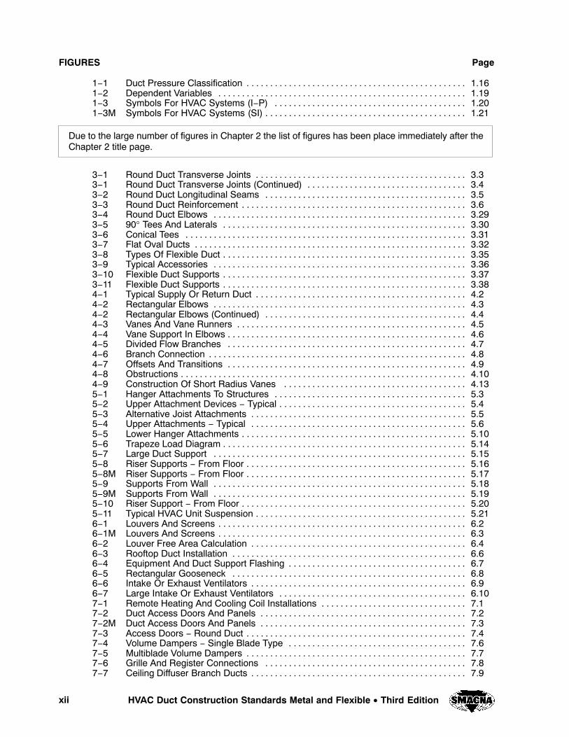
FIGURES Page
1−1 Duct Pressure Classification 1.16 . . . . . . . . . . . . . . . . . . . . . . . . . . . . . . . . . . . . . . . . . . . . . . . 1−2 Dependent Variables 1.19 . . . . . . . . . . . . . . . . . . . . . . . . . . . . . . . . . . . . . . . . . . . . . . . . . . . . . 1−3 Symbols For HVAC Systems (I−P) 1.20 . . . . . . . . . . . . . . . . . . . . . . . . . . . . . . . . . . . . . . . . . 1−3M Symbols For HVAC Systems (SI) 1.21 . . . . . . . . . . . . . . . . . . . . . . . . . . . . . . . . . . . . . . . . . . .
Due to the large number of figures in Chapter 2 the list of figures has been place immediately after theChapter 2 title page.
3−1 Round Duct Transverse Joints 3.3 . . . . . . . . . . . . . . . . . . . . . . . . . . . . . . . . . . . . . . . . . . . . . 3−1 Round Duct Transverse Joints (Continued) 3.4 . . . . . . . . . . . . . . . . . . . . . . . . . . . . . . . . . . 3−2 Round Duct Longitudinal Seams 3.5 . . . . . . . . . . . . . . . . . . . . . . . . . . . . . . . . . . . . . . . . . . . 3−3 Round Duct Reinforcement 3.6 . . . . . . . . . . . . . . . . . . . . . . . . . . . . . . . . . . . . . . . . . . . . . . . . 3−4 Round Duct Elbows 3.29 . . . . . . . . . . . . . . . . . . . . . . . . . . . . . . . . . . . . . . . . . . . . . . . . . . . . . . 3−5 90° Tees And Laterals 3.30 . . . . . . . . . . . . . . . . . . . . . . . . . . . . . . . . . . . . . . . . . . . . . . . . . . . . 3−6 Conical Tees 3.31 . . . . . . . . . . . . . . . . . . . . . . . . . . . . . . . . . . . . . . . . . . . . . . . . . . . . . . . . . . . . 3−7 Flat Oval Ducts 3.32 . . . . . . . . . . . . . . . . . . . . . . . . . . . . . . . . . . . . . . . . . . . . . . . . . . . . . . . . . . 3−8 Types Of Flexible Duct 3.35 . . . . . . . . . . . . . . . . . . . . . . . . . . . . . . . . . . . . . . . . . . . . . . . . . . . . 3−9 Typical Accessories 3.36 . . . . . . . . . . . . . . . . . . . . . . . . . . . . . . . . . . . . . . . . . . . . . . . . . . . . . . 3−10 Flexible Duct Supports 3.37 . . . . . . . . . . . . . . . . . . . . . . . . . . . . . . . . . . . . . . . . . . . . . . . . . . . . 3−11 Flexible Duct Supports 3.38 . . . . . . . . . . . . . . . . . . . . . . . . . . . . . . . . . . . . . . . . . . . . . . . . . . . . 4−1 Typical Supply Or Return Duct 4.2 . . . . . . . . . . . . . . . . . . . . . . . . . . . . . . . . . . . . . . . . . . . . . 4−2 Rectangular Elbows 4.3 . . . . . . . . . . . . . . . . . . . . . . . . . . . . . . . . . . . . . . . . . . . . . . . . . . . . . . 4−2 Rectangular Elbows (Continued) 4.4 . . . . . . . . . . . . . . . . . . . . . . . . . . . . . . . . . . . . . . . . . . . 4−3 Vanes And Vane Runners 4.5 . . . . . . . . . . . . . . . . . . . . . . . . . . . . . . . . . . . . . . . . . . . . . . . . . 4−4 Vane Support In Elbows 4.6 . . . . . . . . . . . . . . . . . . . . . . . . . . . . . . . . . . . . . . . . . . . . . . . . . . . 4−5 Divided Flow Branches 4.7 . . . . . . . . . . . . . . . . . . . . . . . . . . . . . . . . . . . . . . . . . . . . . . . . . . . 4−6 Branch Connection 4.8 . . . . . . . . . . . . . . . . . . . . . . . . . . . . . . . . . . . . . . . . . . . . . . . . . . . . . . . 4−7 Offsets And Transitions 4.9 . . . . . . . . . . . . . . . . . . . . . . . . . . . . . . . . . . . . . . . . . . . . . . . . . . . 4−8 Obstructions 4.10 . . . . . . . . . . . . . . . . . . . . . . . . . . . . . . . . . . . . . . . . . . . . . . . . . . . . . . . . . . . . . 4−9 Construction Of Short Radius Vanes 4.13 . . . . . . . . . . . . . . . . . . . . . . . . . . . . . . . . . . . . . . . 5−1 Hanger Attachments To Structures 5.3 . . . . . . . . . . . . . . . . . . . . . . . . . . . . . . . . . . . . . . . . . 5−2 Upper Attachment Devices − Typical 5.4 . . . . . . . . . . . . . . . . . . . . . . . . . . . . . . . . . . . . . . . . 5−3 Alternative Joist Attachments 5.5 . . . . . . . . . . . . . . . . . . . . . . . . . . . . . . . . . . . . . . . . . . . . . . 5−4 Upper Attachments − Typical 5.6 . . . . . . . . . . . . . . . . . . . . . . . . . . . . . . . . . . . . . . . . . . . . . . 5−5 Lower Hanger Attachments 5.10 . . . . . . . . . . . . . . . . . . . . . . . . . . . . . . . . . . . . . . . . . . . . . . . . 5−6 Trapeze Load Diagram 5.14 . . . . . . . . . . . . . . . . . . . . . . . . . . . . . . . . . . . . . . . . . . . . . . . . . . . . 5−7 Large Duct Support 5.15 . . . . . . . . . . . . . . . . . . . . . . . . . . . . . . . . . . . . . . . . . . . . . . . . . . . . . . 5−8 Riser Supports − From Floor 5.16 . . . . . . . . . . . . . . . . . . . . . . . . . . . . . . . . . . . . . . . . . . . . . . . 5−8M Riser Supports − From Floor 5.17. . . . . . . . . . . . . . . . . . . . . . . . . . . . . . . . . . . . . . . . . . . . . . . 5−9 Supports From Wall 5.18 . . . . . . . . . . . . . . . . . . . . . . . . . . . . . . . . . . . . . . . . . . . . . . . . . . . . . . 5−9M Supports From Wall 5.19. . . . . . . . . . . . . . . . . . . . . . . . . . . . . . . . . . . . . . . . . . . . . . . . . . . . . . 5−10 Riser Support − From Floor 5.20 . . . . . . . . . . . . . . . . . . . . . . . . . . . . . . . . . . . . . . . . . . . . . . . . 5−11 Typical HVAC Unit Suspension 5.21 . . . . . . . . . . . . . . . . . . . . . . . . . . . . . . . . . . . . . . . . . . . . . 6−1 Louvers And Screens 6.2 . . . . . . . . . . . . . . . . . . . . . . . . . . . . . . . . . . . . . . . . . . . . . . . . . . . . . 6−1M Louvers And Screens 6.3 . . . . . . . . . . . . . . . . . . . . . . . . . . . . . . . . . . . . . . . . . . . . . . . . . . . . . 6−2 Louver Free Area Calculation 6.4 . . . . . . . . . . . . . . . . . . . . . . . . . . . . . . . . . . . . . . . . . . . . . . 6−3 Rooftop Duct Installation 6.6 . . . . . . . . . . . . . . . . . . . . . . . . . . . . . . . . . . . . . . . . . . . . . . . . . . 6−4 Equipment And Duct Support Flashing 6.7 . . . . . . . . . . . . . . . . . . . . . . . . . . . . . . . . . . . . . . 6−5 Rectangular Gooseneck 6.8 . . . . . . . . . . . . . . . . . . . . . . . . . . . . . . . . . . . . . . . . . . . . . . . . . . 6−6 Intake Or Exhaust Ventilators 6.9 . . . . . . . . . . . . . . . . . . . . . . . . . . . . . . . . . . . . . . . . . . . . . . 6−7 Large Intake Or Exhaust Ventilators 6.10 . . . . . . . . . . . . . . . . . . . . . . . . . . . . . . . . . . . . . . . . 7−1 Remote Heating And Cooling Coil Installations 7.1 . . . . . . . . . . . . . . . . . . . . . . . . . . . . . . . 7−2 Duct Access Doors And Panels 7.2 . . . . . . . . . . . . . . . . . . . . . . . . . . . . . . . . . . . . . . . . . . . . 7−2M Duct Access Doors And Panels 7.3. . . . . . . . . . . . . . . . . . . . . . . . . . . . . . . . . . . . . . . . . . . . 7−3 Access Doors − Round Duct 7.4 . . . . . . . . . . . . . . . . . . . . . . . . . . . . . . . . . . . . . . . . . . . . . . . 7−4 Volume Dampers − Single Blade Type 7.6 . . . . . . . . . . . . . . . . . . . . . . . . . . . . . . . . . . . . . . 7−5 Multiblade Volume Dampers 7.7 . . . . . . . . . . . . . . . . . . . . . . . . . . . . . . . . . . . . . . . . . . . . . . . 7−6 Grille And Register Connections 7.8 . . . . . . . . . . . . . . . . . . . . . . . . . . . . . . . . . . . . . . . . . . . 7−7 Ceiling Diffuser Branch Ducts 7.9 . . . . . . . . . . . . . . . . . . . . . . . . . . . . . . . . . . . . . . . . . . . . . .
xiiiHVAC Duct Construction Standards Metal and Flexible • Third Edition
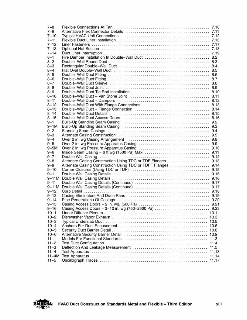
7−8 Flexible Connections At Fan 7.10 . . . . . . . . . . . . . . . . . . . . . . . . . . . . . . . . . . . . . . . . . . . . . . . 7−9 Alternative Flex Connector Details 7.11 . . . . . . . . . . . . . . . . . . . . . . . . . . . . . . . . . . . . . . . . . . 7−10 Typical HVAC Unit Connections 7.12 . . . . . . . . . . . . . . . . . . . . . . . . . . . . . . . . . . . . . . . . . . . 7−11 Flexible Duct Liner Installation 7.13 . . . . . . . . . . . . . . . . . . . . . . . . . . . . . . . . . . . . . . . . . . . . . 7−12 Liner Fasteners 7.17 . . . . . . . . . . . . . . . . . . . . . . . . . . . . . . . . . . . . . . . . . . . . . . . . . . . . . . . . . . 7−13 Optional Hat Section 7.18 . . . . . . . . . . . . . . . . . . . . . . . . . . . . . . . . . . . . . . . . . . . . . . . . . . . . . 7−14 Duct Liner Interruption 7.19 . . . . . . . . . . . . . . . . . . . . . . . . . . . . . . . . . . . . . . . . . . . . . . . . . . . . 8−1 Fire Damper Installation In Double−Wall Duct 8.2 . . . . . . . . . . . . . . . . . . . . . . . . . . . . . . . . 8−2 Double−Wall Round Duct 8.3. . . . . . . . . . . . . . . . . . . . . . . . . . . . . . . . . . . . . . . . . . . . . . . . . . 8−3 Rectangular Double−Wall Duct 8.4 . . . . . . . . . . . . . . . . . . . . . . . . . . . . . . . . . . . . . . . . . . . . . 8−4 Flat Oval Double−Wall Duct 8.5 . . . . . . . . . . . . . . . . . . . . . . . . . . . . . . . . . . . . . . . . . . . . . . . 8−5 Double−Wall Duct Fitting 8.6 . . . . . . . . . . . . . . . . . . . . . . . . . . . . . . . . . . . . . . . . . . . . . . . . . . 8−6 Double−Wall Duct Fitting 8.7 . . . . . . . . . . . . . . . . . . . . . . . . . . . . . . . . . . . . . . . . . . . . . . . . . . 8−7 Double−Wall Duct Sleeve 8.8 . . . . . . . . . . . . . . . . . . . . . . . . . . . . . . . . . . . . . . . . . . . . . . . . . 8−8 Double−Wall Duct Joint 8.9 . . . . . . . . . . . . . . . . . . . . . . . . . . . . . . . . . . . . . . . . . . . . . . . . . . . 8−9 Double−Wall Duct Tie Rod Installation 8.10 . . . . . . . . . . . . . . . . . . . . . . . . . . . . . . . . . . . . . . 8−10 Double−Wall Duct – Van Stone Joint 8.11 . . . . . . . . . . . . . . . . . . . . . . . . . . . . . . . . . . . . . . . . 8−11 Double−Wall Duct – Dampers 8.12 . . . . . . . . . . . . . . . . . . . . . . . . . . . . . . . . . . . . . . . . . . . . . . 8−12 Double−Wall Duct With Flange Connections 8.13 . . . . . . . . . . . . . . . . . . . . . . . . . . . . . . . . . 8−13 Double−Wall Duct – Flange Connection 8.14 . . . . . . . . . . . . . . . . . . . . . . . . . . . . . . . . . . . . . 8−14 Double−Wall Duct Details 8.15 . . . . . . . . . . . . . . . . . . . . . . . . . . . . . . . . . . . . . . . . . . . . . . . . . 8−15 Double−Wall Duct Access Doors 8.16 . . . . . . . . . . . . . . . . . . . . . . . . . . . . . . . . . . . . . . . . . . . 9−1 Built−Up Standing Seam Casing 9.2 . . . . . . . . . . . . . . . . . . . . . . . . . . . . . . . . . . . . . . . . . . . 9−1M Built−Up Standing Seam Casing 9.3 . . . . . . . . . . . . . . . . . . . . . . . . . . . . . . . . . . . . . . . . . . . 9−2 Standing Seam Casings 9.4 . . . . . . . . . . . . . . . . . . . . . . . . . . . . . . . . . . . . . . . . . . . . . . . . . . 9−3 Alternate Casing Construction 9.5 . . . . . . . . . . . . . . . . . . . . . . . . . . . . . . . . . . . . . . . . . . . . . 9−4 Over 2 in. wg Casing Arrangement 9.8 . . . . . . . . . . . . . . . . . . . . . . . . . . . . . . . . . . . . . . . . . 9−5 Over 2 in. wg Pressure Apparatus Casing 9.9 . . . . . . . . . . . . . . . . . . . . . . . . . . . . . . . . . . . 9−5M Over 2 in. wg Pressure Apparatus Casing 9.10. . . . . . . . . . . . . . . . . . . . . . . . . . . . . . . . . . . 9−6 Inside Seam Casing − 6 ft wg (1500 Pa) Max. 9.11 . . . . . . . . . . . . . . . . . . . . . . . . . . . . . . . . 9−7 Double Wall Casing 9.12 . . . . . . . . . . . . . . . . . . . . . . . . . . . . . . . . . . . . . . . . . . . . . . . . . . . . . . 9−8 Alternate Casing Construction Using TDC or TDF Flanges 9.13 . . . . . . . . . . . . . . . . . . . . . 9−9 Alternate Casing Construction Using TDC or TDFF Flanges 9.14 . . . . . . . . . . . . . . . . . . . 9−10 Corner Closures (Using TDC or TDF) 9.15 . . . . . . . . . . . . . . . . . . . . . . . . . . . . . . . . . . . . . . . 9−11 Double Wall Casing Details 9.16 . . . . . . . . . . . . . . . . . . . . . . . . . . . . . . . . . . . . . . . . . . . . . . . . 9−11M Double Wall Casing Details 9.16. . . . . . . . . . . . . . . . . . . . . . . . . . . . . . . . . . . . . . . . . . . . . . . . 9−11 Double Wall Casing Details (Continued) 9.17 . . . . . . . . . . . . . . . . . . . . . . . . . . . . . . . . . . . . . 9−11M Double Wall Casing Details (Continued) 9.17. . . . . . . . . . . . . . . . . . . . . . . . . . . . . . . . . . . . . 9−12 Curb Detail 9.18 . . . . . . . . . . . . . . . . . . . . . . . . . . . . . . . . . . . . . . . . . . . . . . . . . . . . . . . . . . . . . . 9−13 Casing Eliminators And Drain Pans 9.19 . . . . . . . . . . . . . . . . . . . . . . . . . . . . . . . . . . . . . . . . . 9−14 Pipe Penetrations Of Casings 9.20 . . . . . . . . . . . . . . . . . . . . . . . . . . . . . . . . . . . . . . . . . . . . . . 9−15 Casing Access Doors − 2 in. wg. (500 Pa) 9.21 . . . . . . . . . . . . . . . . . . . . . . . . . . . . . . . . . . . 9−16 Casing Access Doors − 3−10 in. wg (750−2500 Pa) 9.23 . . . . . . . . . . . . . . . . . . . . . . . . . . . 10−1 Linear Diffuser Plenum 10.1 . . . . . . . . . . . . . . . . . . . . . . . . . . . . . . . . . . . . . . . . . . . . . . . . . . . 10−2 Dishwasher Vapor Exhaust 10.3 . . . . . . . . . . . . . . . . . . . . . . . . . . . . . . . . . . . . . . . . . . . . . . . 10−3 Typical Underslab Duct 10.5 . . . . . . . . . . . . . . . . . . . . . . . . . . . . . . . . . . . . . . . . . . . . . . . . . . 10−4 Anchors For Duct Encasement 10.6 . . . . . . . . . . . . . . . . . . . . . . . . . . . . . . . . . . . . . . . . . . . . 10−5 Security Duct Barrier Detail 10.8 . . . . . . . . . . . . . . . . . . . . . . . . . . . . . . . . . . . . . . . . . . . . . . . 10−6 Alternative Security Barrier Detail 10.9 . . . . . . . . . . . . . . . . . . . . . . . . . . . . . . . . . . . . . . . . . 11−1 Models For Functional Standards 11.3 . . . . . . . . . . . . . . . . . . . . . . . . . . . . . . . . . . . . . . . . . 11−2 Test Duct Configuration 11.4 . . . . . . . . . . . . . . . . . . . . . . . . . . . . . . . . . . . . . . . . . . . . . . . . . . 11−3 Deflection And Leakage Measurement 11.5 . . . . . . . . . . . . . . . . . . . . . . . . . . . . . . . . . . . . . 11−4 Test Apparatus 11.13 . . . . . . . . . . . . . . . . . . . . . . . . . . . . . . . . . . . . . . . . . . . . . . . . . . . . . . . . . 11−4M Test Apparatus 11.14 . . . . . . . . . . . . . . . . . . . . . . . . . . . . . . . . . . . . . . . . . . . . . . . . . . . . . . . . . 11−5 Oscillograph Traces 11.17 . . . . . . . . . . . . . . . . . . . . . . . . . . . . . . . . . . . . . . . . . . . . . . . . . . . . .

xiv HVAC Duct Construction Standards Metal and Flexible • Third Edition
CHARTS Page
4−1 Number of Short Radius Vanes 4.11 . . . . . . . . . . . . . . . . . . . . . . . . . . . . . . . . . . . . . . . . . . . . 4−1M Number of Short Radius Vanes 4.12 . . . . . . . . . . . . . . . . . . . . . . . . . . . . . . . . . . . . . . . . . . . .

ENGINEERING AND DESIGN
CHAPTER 1

ENGINEERING AND DESIGNCHAPTER 1
1.1HVAC Duct Construction Standards Metal and Flexible • Third Edition
1.1 INTRODUCTION
This chapter is intended to provide the design profes-
sional an understanding of the concepts involved in
HVAC duct construction and guidance as to the re-
quired elements which are necessary in project plans
and specifications to allow the fabricating and instal-
ling contractor to provide a duct system which meets
the requirements of those plans and specifications.
1.2 INFORMATION REQUIRED FORDUCT CONSTRUCTION
Various types of information are required in project
plans and specifications in order for the fabricating
and installing contractor to provide the duct system
performance intended by the system designer. Among
those are:
1. A comprehensive duct layout indicating
sizes, design airflows, pressure class, and
routing of the duct system.
2. The types of fittings to be used based on the
designer’s calculations of fitting losses (i.e.,
square versus 45 degrees entry taps, conical
versus straight taps, etc.).
3. Use of turning vanes or splitter vanes.
4. Location of access doors.
5. Location and type of control and balancing
dampers.
6. Location and types of diffusers.
7. Requirements for duct insulation.
8. Location and types of any fire protection de-
vice including fire dampers, smoke dampers,
combination fire/smoke dampers, and ceiling
dampers. Building codes require this infor-
mation to be shown on the design documents
submitted for building permit.
NOTE: UL 555 (Fire Dampers) and UL 555S (Smoke
Dampers) now indicate three velocity ratings and
three pressure ratings for dynamic Fire, Smoke and
Combination Fire/Smoke Dampers. It is recommended
that a schedule of these dampers be included with
equipment schedules in order to insure that the correct
damper is used.
9. Details of offsets required to route ductwork
around obstructions (columns, beams, etc.).
1.3 MODEL SPECIFICATIONS
Specification sections designated with an S are obliga-
tory.
1.3.1 Duct Construction and InstallationStandards
S1.0 General Requirements
S1.1 These construction and installation specifica-
tions and illustrations include:
a. Single−prescriptive method require-ments,
b. Optional alternatives, and
c. Performance requirements for specific
items that are different in detail from the
generalized illustrations.
S1.2 These standards are not meant to exclude any
products or methods that can be demon-
strated to be equivalent in performance for
the application. Substitutions based on spon-
sor demonstrated adequacy and approval of
the regulating authority are recognized.
S1.3 These requirements presume that the design-
ers have prepared contract drawings showing
the size and location of ductwork, including
permissible fitting configurations. Where
area change, direction change, divided flow,
or united flow fittings other than those illus-
trated here are shown on the contract draw-
ings, are not of proprietary manufacture, and
are defined with friction loss coefficients in
either the SMACNA HVAC Systems Duct De-
sign manual or the ASHRAE Handbook −
Fundamentals chapter on duct design, such
fittings shall be fabricated with materials, as-
sembly techniques, and sealing provisions
given here.
S1.4 EACH DUCT SYSTEM SHALL BE
CONSTRUCTED FOR THE SPECIFIC
DUCT PRESSURE CLASSIFICATIONS
SHOWN ON THE CONTRACT DRAW-
INGS. WHERE NO PRESSURE CLASSES
ARE SPECIFIED BY THE DESIGNER,
THE 1 IN. WG (250 Pa) PRESSURE CLASS
IS THE BASIS OF COMPLIANCE WITH
THESE STANDARDS, REGARDLESS OF
VELOCITY IN THE DUCT, EXCEPT
WHEN THE DUCT IS VARIABLE VOL-