husky 55 manual
TRANSCRIPT

8/7/2019 Husky 55 Manual
http://slidepdf.com/reader/full/husky-55-manual 1/36
Operator's manual (EPA)
Please read these instructions carefully and makesure you understand them before using the machine. English
55
8/7/2019 Husky 55 Manual
http://slidepdf.com/reader/full/husky-55-manual 2/362 – English
SymbolsKEY TO SYMBOLS
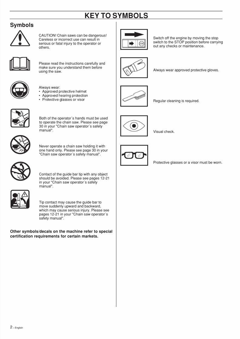
Switch off the engine by moving the stopswitch to the STOP position before carryingout any checks or maintenance.
Always wear approved protective gloves.
Regular cleaning is required.
Visual check.
Protective glasses or a visor must be worn.
CAUTION! Chain saws can be dangerous!Careless or incorrect use can result inserious or fatal injury to the operator orothers.
Please read the instructions carefully andmake sure you understand them beforeusing the saw.
Always wear:• Approved protective helmet• Approved hearing protection• Protective glasses or visor
Both of the operator´s hands must be usedto operate the chain saw. Please see page30 in your "Chain saw operator´s safetymanual".
Never operate a chain saw holding it withone hand only. Please see page 30 in your"Chain saw operator´s safety manual".
Contact of the guide bar tip with any objectshould be avoided. Please see pages 12-21in your "Chain saw operator´s safetymanual".
Tip contact may cause the guide bar tomove suddenly upward and backward,which may cause serious injury. Please seepages 12-21 in your "Chain saw operator´ssafety manual".
Other symbols/decals on the machine refer to special
certification requirements for certain markets.
8/7/2019 Husky 55 Manual
http://slidepdf.com/reader/full/husky-55-manual 3/36
8/7/2019 Husky 55 Manual
http://slidepdf.com/reader/full/husky-55-manual 4/364 – English
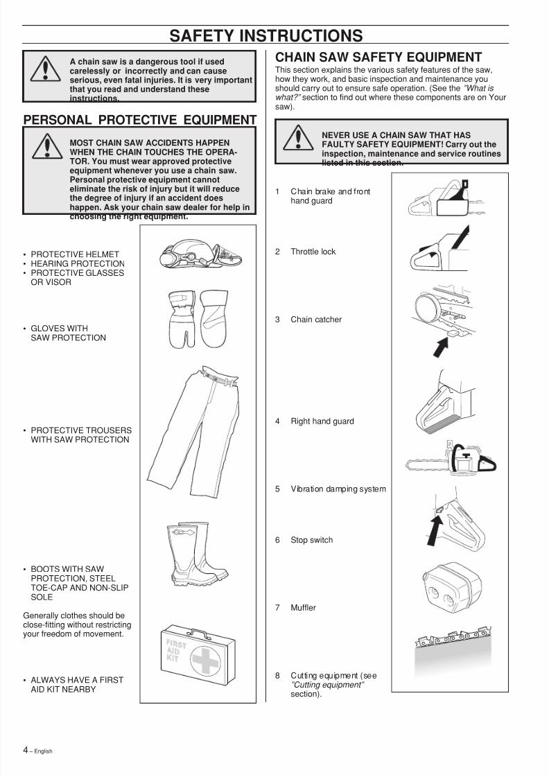
CHAIN SAW SAFETY EQUIPMENTThis section explains the various safety features of the saw,how they work, and basic inspection and maintenance youshould carry out to ensure safe operation. (See the ”What is what?” section to find out where these components are on Yoursaw).
NEVER USE A CHAIN SAW THAT HASFAULTY SAFETY EQUIPMENT! Carry out theinspection, maintenance and service routineslisted in this section.
1 Chain brake and fronthand guard
2 Throttle lock
3 Chain catcher
4 Right hand guard
5 Vibration damping system
6 Stop switch
7 Muffler
8 Cutting equipment (see”Cutting equipment” section).
SAFETY INSTRUCTIONSA chain saw is a dangerous tool if usedcarelessly or incorrectly and can causeserious, even fatal injuries. It is very importantthat you read and understand theseinstructions.
PERSONAL PROTECTIVE EQUIPMENT
MOST CHAIN SAW ACCIDENTS HAPPENWHEN THE CHAIN TOUCHES THE OPERA-TOR. You must wear approved protectiveequipment whenever you use a chain saw.Personal protective equipment cannoteliminate the risk of injury but it will reducethe degree of injury if an accident doeshappen. Ask your chain saw dealer for help inchoosing the right equipment.
• PROTECTIVE HELMET• HEARING PROTECTION• PROTECTIVE GLASSES
OR VISOR
• GLOVES WITHSAW PROTECTION
• PROTECTIVE TROUSERSWITH SAW PROTECTION
• BOOTS WITH SAWPROTECTION, STEELTOE-CAP AND NON-SLIPSOLE
Generally clothes should beclose-fitting without restrictingyour freedom of movement.
• ALWAYS HAVE A FIRSTAID KIT NEARBY
8/7/2019 Husky 55 Manual
http://slidepdf.com/reader/full/husky-55-manual 5/36English – 5
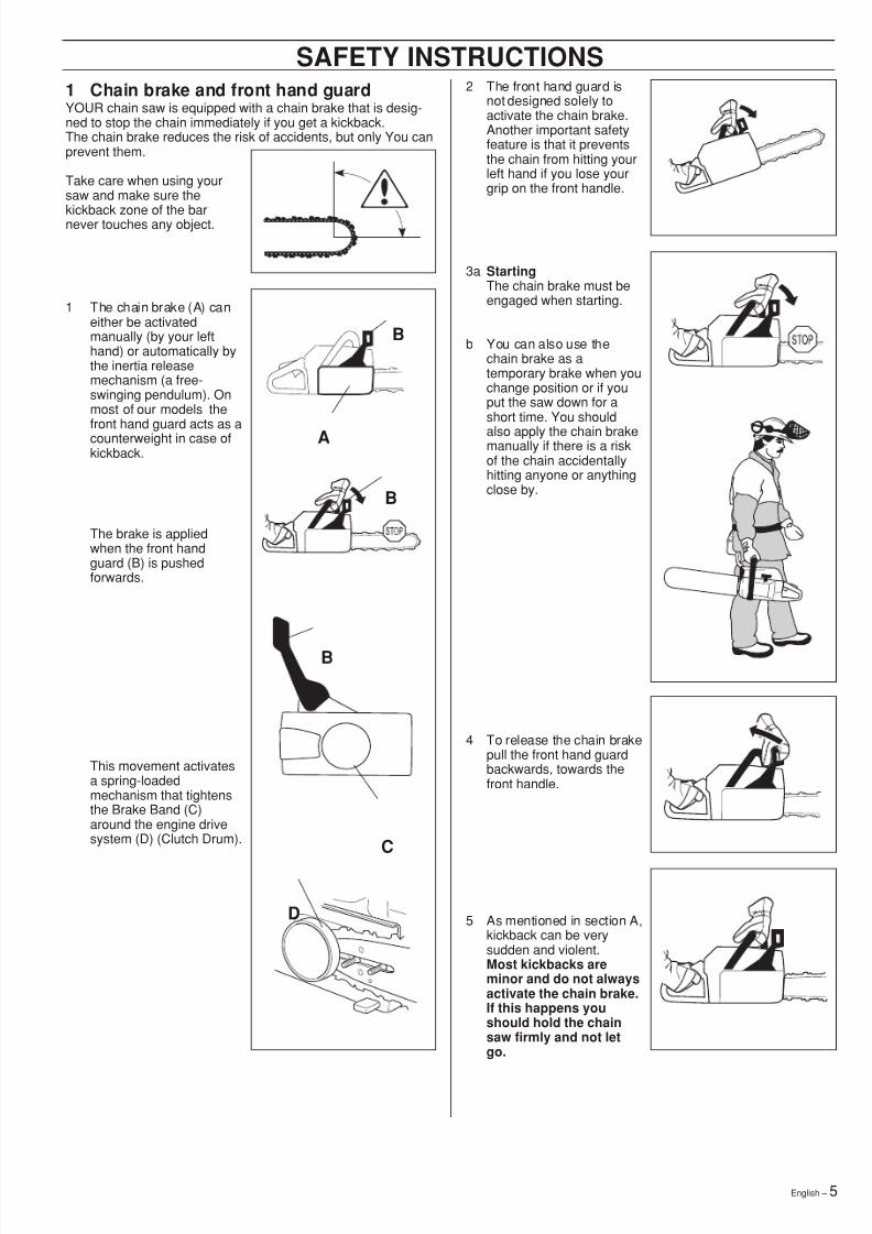
1 Chain brake and front hand guardYOUR chain saw is equipped with a chain brake that is desig-ned to stop the chain immediately if you get a kickback.The chain brake reduces the risk of accidents, but only You canprevent them.
Take care when using yoursaw and make sure the
kickback zone of the barnever touches any object.
1 The chain brake (A) caneither be activatedmanually (by your lefthand) or automatically bythe inertia releasemechanism (a free-swinging pendulum). Onmost of our models thefront hand guard acts as acounterweight in case ofkickback.
The brake is appliedwhen the front handguard (B) is pushedforwards.
This movement activatesa spring-loadedmechanism that tightensthe Brake Band (C)around the engine drivesystem (D) (Clutch Drum).
SAFETY INSTRUCTIONS2 The front hand guard is
not designed solely toactivate the chain brake.Another important safetyfeature is that it preventsthe chain from hitting yourleft hand if you lose yourgrip on the front handle.
3a StartingThe chain brake must beengaged when starting.
b You can also use thechain brake as atemporary brake when youchange position or if youput the saw down for ashort time. You should
also apply the chain brakemanually if there is a riskof the chain accidentallyhitting anyone or anythingclose by.
4 To release the chain brakepull the front hand guardbackwards, towards thefront handle.
5 As mentioned in section A,kickback can be verysudden and violent.Most kickbacks areminor and do not alwaysactivate the chain brake.If this happens youshould hold the chainsaw firmly and not letgo.
A
B
B
D
B
C
8/7/2019 Husky 55 Manual
http://slidepdf.com/reader/full/husky-55-manual 6/366 – English
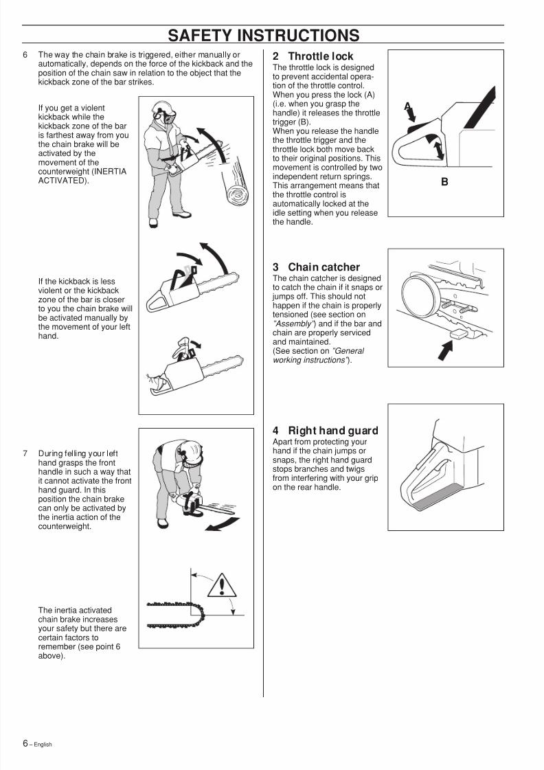
6 The way the chain brake is triggered, either manually orautomatically, depends on the force of the kickback and theposition of the chain saw in relation to the object that thekickback zone of the bar strikes.
If you get a violentkickback while thekickback zone of the baris farthest away from youthe chain brake will beactivated by themovement of thecounterweight (INERTIAACTIVATED).
If the kickback is lessviolent or the kickbackzone of the bar is closerto you the chain brake willbe activated manually bythe movement of your lefthand.
7 During felling your lefthand grasps the fronthandle in such a way thatit cannot activate the fronthand guard. In thisposition the chain brakecan only be activated bythe inertia action of thecounterweight.
The inertia activatedchain brake increasesyour safety but there arecertain factors toremember (see point 6above).
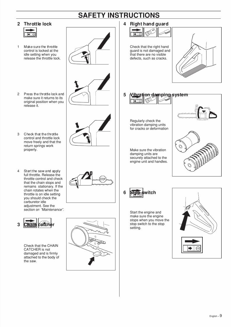
2 Throttle lockThe throttle lock is designedto prevent accidental opera-tion of the throttle control.When you press the lock (A)(i.e. when you grasp thehandle) it releases the throttletrigger (B).
When you release the handlethe throttle trigger and thethrottle lock both move backto their original positions. Thismovement is controlled by twoindependent return springs.This arrangement means thatthe throttle control isautomatically locked at theidle setting when you releasethe handle.
3 Chain catcherThe chain catcher is designedto catch the chain if it snaps or
jumps off. This should nothappen if the chain is properlytensioned (see section on”Assembly” ) and if the bar andchain are properly servicedand maintained.(See section on ”General working instructions” ).
4 Right hand guardApart from protecting yourhand if the chain jumps orsnaps, the right hand guardstops branches and twigsfrom interfering with your gripon the rear handle.
A
B
SAFETY INSTRUCTIONS
8/7/2019 Husky 55 Manual
http://slidepdf.com/reader/full/husky-55-manual 7/36
8/7/2019 Husky 55 Manual
http://slidepdf.com/reader/full/husky-55-manual 8/368 – English
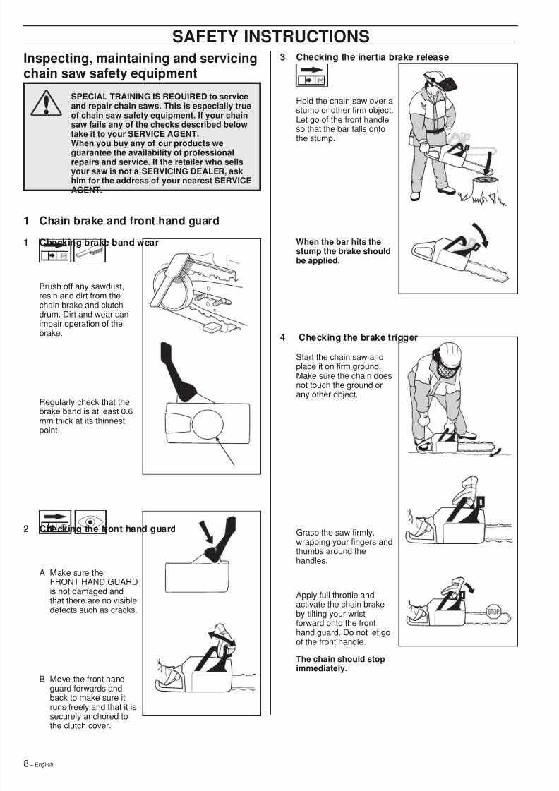
3 Checking the inertia brake release
Hold the chain saw over astump or other firm object.Let go of the front handleso that the bar falls ontothe stump.
When the bar hits thestump the brake shouldbe applied.
Inspecting, maintaining and servicingchain saw safety equipment
SPECIAL TRAINING IS REQUIRED to serviceand repair chain saws. This is especially trueof chain saw safety equipment. If your chainsaw fails any of the checks described below
take it to your SERVICE AGENT.When you buy any of our products weguarantee the availability of professionalrepairs and service. If the retailer who sellsyour saw is not a SERVICING DEALER, askhim for the address of your nearest SERVICEAGENT.
1 Chain brake and front hand guard
1 Checking brake band wear
Brush off any sawdust,resin and dirt from thechain brake and clutchdrum. Dirt and wear canimpair operation of thebrake.
Regularly check that the
brake band is at least 0.6mm thick at its thinnestpoint.
SAFETY INSTRUCTIONS
4 Checking the brake trigger
Start the chain saw andplace it on firm ground.Make sure the chain doesnot touch the ground orany other object.
Grasp the saw firmly,wrapping your fingers and
thumbs around thehandles.
Apply full throttle andactivate the chain brakeby tilting your wristforward onto the fronthand guard. Do not let goof the front handle.
The chain should stopimmediately.
2 Checking the front hand guard
A Make sure theFRONT HAND GUARDis not damaged andthat there are no visibledefects such as cracks.
B Move the front hand
guard forwards andback to make sure itruns freely and that it issecurely anchored tothe clutch cover.
8/7/2019 Husky 55 Manual
http://slidepdf.com/reader/full/husky-55-manual 9/36
8/7/2019 Husky 55 Manual
http://slidepdf.com/reader/full/husky-55-manual 10/3610 – English
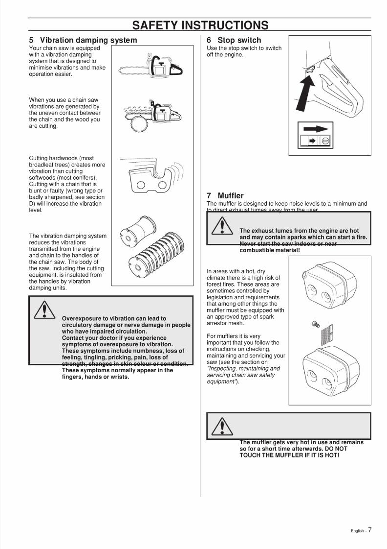
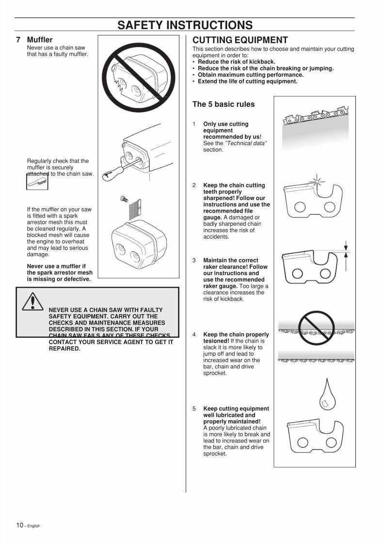
7 MufflerNever use a chain sawthat has a faulty muffler.
Regularly check that themuffler is securelyattached to the chain saw.
If the muffler on your sawis fitted with a sparkarrestor mesh this mustbe cleaned regularly. Ablocked mesh will causethe engine to overheatand may lead to seriousdamage.
Never use a muffler ifthe spark arrestor meshis missing or defective.
NEVER USE A CHAIN SAW WITH FAULTYSAFETY EQUIPMENT. CARRY OUT THECHECKS AND MAINTENANCE MEASURESDESCRIBED IN THIS SECTION. IF YOURCHAIN SAW FAILS ANY OF THESE CHECKSCONTACT YOUR SERVICE AGENT TO GET ITREPAIRED.
CUTTING EQUIPMENTThis section describes how to choose and maintain your cuttingequipment in order to:• Reduce the risk of kickback.• Reduce the risk of the chain breaking or jumping.• Obtain maximum cutting performance.• Extend the life of cutting equipment.
The 5 basic rules
1 Only use cuttingequipmentrecommended by us!See the ”Technical data” section.
2 Keep the chain cuttingteeth properlysharpened! Follow ourinstructions and use therecommended filegauge. A damaged orbadly sharpened chainincreases the risk ofaccidents.
3 Maintain the correctraker clearance! Followour instructions anduse the recommendedraker gauge. Too large aclearance increases therisk of kickback.
4 Keep the chain properlytesioned! If the chain isslack it is more likely to
jump off and lead toincreased wear on thebar, chain and drivesprocket.
5 Keep cutting equipmentwell lubricated andproperly maintained!A poorly lubricated chainis more likely to break andlead to increased wear onthe bar, chain and drivesprocket.
SAFETY INSTRUCTIONS
8/7/2019 Husky 55 Manual
http://slidepdf.com/reader/full/husky-55-manual 11/36English – 11
SAFETY INSTRUCTIONSC Some terms that describe the bar and chainWhen the cutting equipment supplied with your saw becomesworn or damaged you will need to replace it. Use only the typeof bar and chain recommended by us. See the ”Technical data”
section to find out which equipment is recommended for yoursaw.
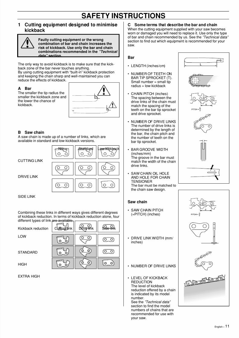
Bar• LENGTH (inches/cm)
• NUMBER OF TEETH ONBAR TIP SPROCKET (T).Small number = small tipradius = low-kickback
• CHAIN PITCH (inches)The spacing between thedrive links of the chain mustmatch the spacing of theteeth on the bar tip sprocketand drive sprocket.
• NUMBER OF DRIVE LINKSThe number of drive links isdetermined by the length ofthe bar, the chain pitch andthe number of teeth on thebar tip sprocket.
• BAR GROOVE WIDTH(inches/mm)The groove in the bar mustmatch the width of the chaindrive links.
• SAW CHAIN OIL HOLEAND HOLE FOR CHAINTENSIONERThe bar must be matched tothe chain saw design.
Saw chain
• SAW CHAIN PITCH(=PITCH) (inches)
• DRIVE LINK WIDTH (mm/ inches)
• NUMBER OF DRIVE LINKS
• LEVEL OF KICKBACKREDUCTIONThe level of kickbackreduction offered by a chainis indicated by its modelnumber.See the ”Technical data”
section to find the modelnumbers of chains that arerecommended for use withyour saw.
1 Cutting equipment designed to minimisekickback
Faulty cutting equipment or the wrongcombination of bar and chain increases therisk of kickback. Use only the bar and chaincombinations recommended in the ”Technical data” section.
The only way to avoid kickback is to make sure that the kick-back zone of the bar never touches anything.By using cutting equipment with “built-in” kickback protectionand keeping the chain sharp and well-maintained you canreduce the effects of kickback.
A BarThe smaller the tip radius thesmaller the kickback zone andthe lower the chance ofkickback.
B Saw chainA saw chain is made up of a number of links, which areavailable in standard and low-kickback versions.
None Standard Low-kickback
CUTTING LINK
DRIVE LINK
SIDE LINK
Combining these links in different ways gives different degreesof kickback reduction. In terms of kickback reduction alone, fourdifferent types of link are available.
Kickback reduction Cutting link Drive link Side link
LOW
STANDARD
HIGH
EXTRA HIGH
8/7/2019 Husky 55 Manual
http://slidepdf.com/reader/full/husky-55-manual 12/36
8/7/2019 Husky 55 Manual
http://slidepdf.com/reader/full/husky-55-manual 13/36English – 13
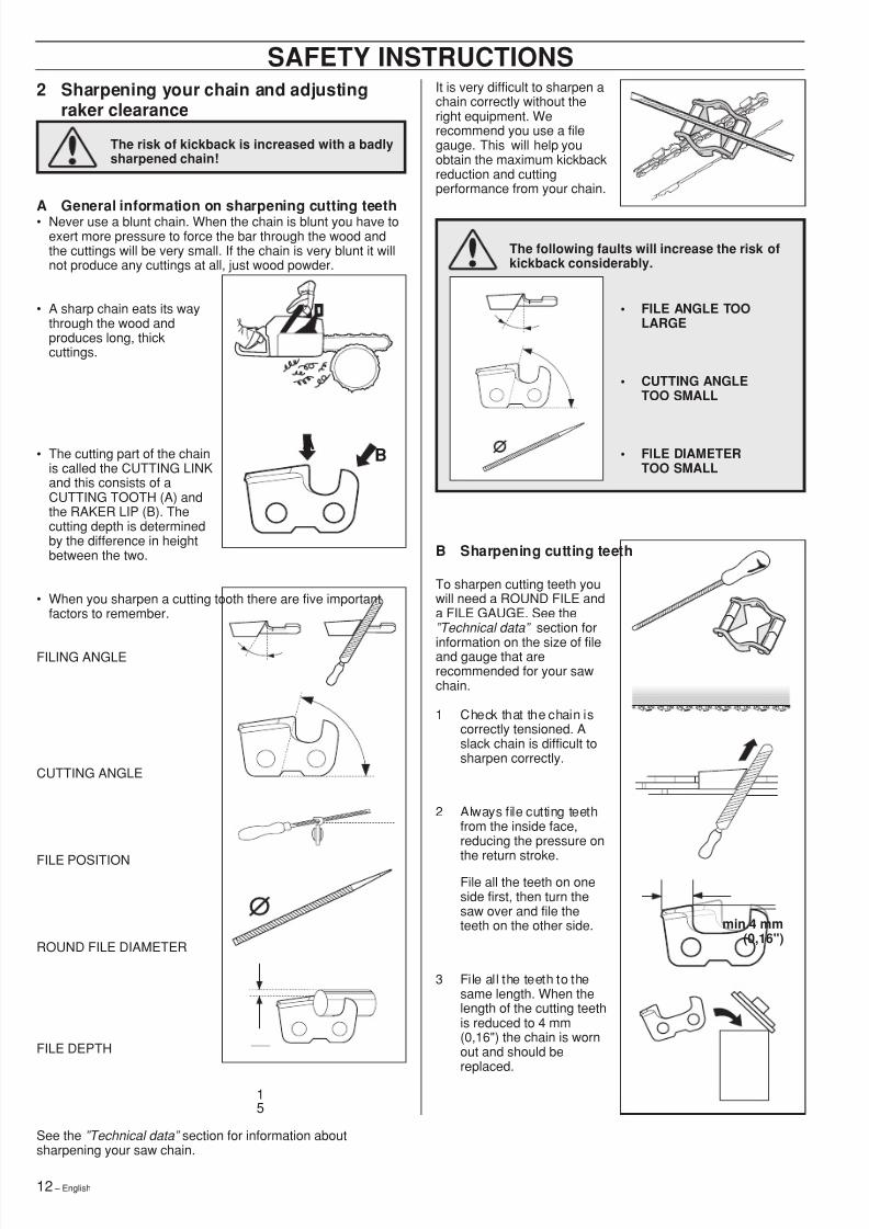
C General advice on setting raker clearance
• When you sharpen thecutting teeth you reduce theRAKER CLEARANCE(cutting depth). To maintaincutting performance youmust file back the rakerteeth to the recommendedheight.
See the ”Technical data” section to find the rakerclearance for your sawchain.
• On a low-kickback cuttinglink the front edge of theraker lip is rounded. It isvery important that youmaintain this radius or bevelwhen you adjust the raker
clearance.• We recommend the use of a
raker gauge to achieve thecorrect clearance and bevelon the raker lip.
The risk of kickback is increased if the rakerclearance is too large!
SAFETY INSTRUCTIONSD Setting the raker clearance
• Before setting the raker clearance the cutting teeth should benewly sharpened.We recommend that you adjust the raker clearance every
third time you sharpen the chain. NOTE! Thisrecommendation assumes that the length of the cutting teethis not reduced excessively.
• To adjust the rakerclearance you will need aFLAT FILE and a RAKERGAUGE.
• Place the gauge over theraker lip.
• Place the file over the partof the lip that protrudesthrough the gauge and fileoff the excess. Theclearance is correct whenyou no longer feel anyresistance as you draw thefile over the gauge.
3 Tensioning the chain
• The more you use a chain the longer it becomes. It istherefore important to adjust the chain regularly to take up theslack.
• Check the chain tension every time you refuel.NOTE! A new saw chain has a running-in period during whichyou should check the tension more frequently.
• Tension the chain as tightlyas possible, but not so tightthat you cannot pull it roundfreely by hand.
A slack chain may jump off and cause seriousor even fatal injury.
8/7/2019 Husky 55 Manual
http://slidepdf.com/reader/full/husky-55-manual 14/3614 – English
SAFETY INSTRUCTIONS4 Lubricating cutting equipment
Poor lubrication of cutting equipment maycause the chain to snap and lead to serious,even fatal injuries.
A Chain oil• Chainsaw chain oil must demonstrate good adhesion to the
chain and also maintain its flow caracteristics regardless ofwhether it is warm summer or cold winter weather.
• As a chainsaw manufacturer we have developed an optimalchain oil which has a vegetable oil base. We recommend theuse of our own oil for both maximum chain life and tominimise environmental damage.
• If our own chain oil is not available, standard chain oil isrecommended.
• In areas where oil specifically for lubrication of saw chains isunavailable, ordinary EP 90 transmission oil may be used.
• Never use waste oil!This is dangerous for yourself, the saw and the environment.
B Filling with chain oil• All our chain saws have an
automatic chain lubricationsystem. On some modelsthe oil flow is alsoadjustable.
• The sizes of the chain oiltank and fuel tank have
been chosen so that thesaw will run out of fuelbefore running out of oil.This means that you shouldnever run with a dry chain.
However, this safety featurerequires that you use theright sort of chain oil (if theoil is too thin it will run outbefore the fuel), and thatyou adjust the carburetor asrecommended (a weakmixture may mean that thefuel lasts longer than theoil). You should also use therecommended cuttingequipment (a bar that is toolong will use more chain oil).The above conditions alsoapply to models with anadjustable oil pump.
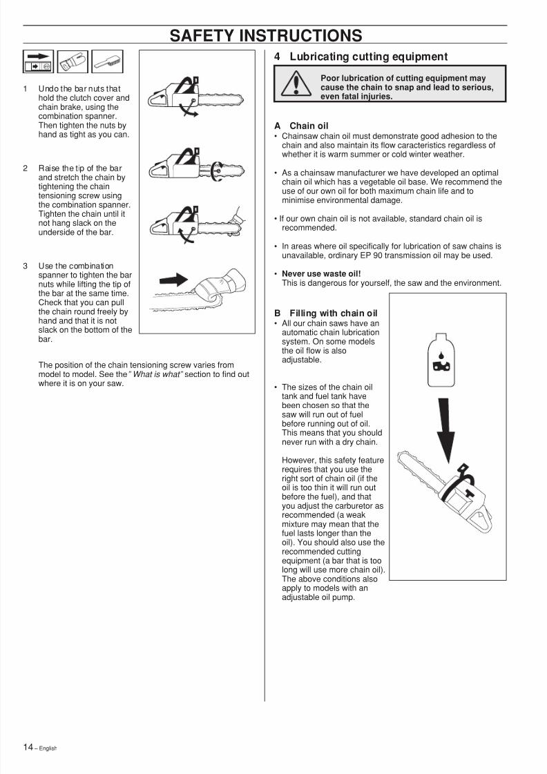
1 Undo the bar nuts thathold the clutch cover andchain brake, using thecombination spanner.Then tighten the nuts by
hand as tight as you can.
2 Raise the tip of the barand stretch the chain bytightening the chaintensioning screw usingthe combination spanner.Tighten the chain until itnot hang slack on theunderside of the bar.
3 Use the combinationspanner to tighten the barnuts while lifting the tip ofthe bar at the same time.Check that you can pullthe chain round freely byhand and that it is notslack on the bottom of thebar.
The position of the chain tensioning screw varies frommodel to model. See the ” What is what” section to find outwhere it is on your saw.
8/7/2019 Husky 55 Manual
http://slidepdf.com/reader/full/husky-55-manual 15/36English – 15
C Checking chain lubrication
• Check the chain lubricationeach time you refuel.
Aim the tip of the saw at alight coloured surface about20 cm away. After 1 minuterunning at 3/4 throttle youshould see a distinct line ofoil on the light surface.
If the chain lubrication is not working:
1 Check that the oil channelin the bar is notobstructed. Clean ifnecessary.
2 Check that the groove inthe edge of the bar isclean. Clean if necessary.
3 Check that the bar tipsprocket turns freely andthat the lubricating hole inthe tip is not blocked.Clean and lubricate ifnecessary.
If the chain lubricationsystem is still not workingafter carrying out theabove measures youshould contact yourservice agent.
D Lubricating the bar tip sprocket
• Lubricate the bar tipsprocket each time yourefuel. Use the specialgrease gun and a goodquality bearing grease.
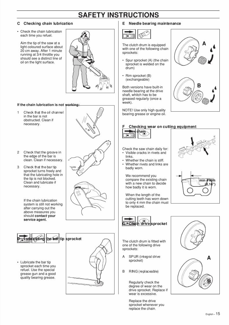
SAFETY INSTRUCTIONSE Needle bearing maintenance
The clutch drum is equippedwith one of the following chainsprockets:
• Spur sprocket (A) (the chainsprocket is welded on thedrum)
• Rim sprocket (B)(exchangeable)
Both versions have built-inneedle bearing at the driveshaft, whitch has to begreased regularly (once aweek).
NOTE! Use only high qualitybearing grease or engine oil.
F Checking wear on cutting equipmentSaw chain
Check the saw chain daily for:• Visible cracks in rivets and
links.• Whether the chain is stiff.• Whether rivets and links are
badly worn.
We recommend youcompare the existing chainwith a new chain to decidehow badly it is worn.
When the length of thecutting teeth has worn downto only 4 mm the chain mustbe replaced.
G Chain drive sprocket
The clutch drum is fitted withone of the following drivesprockets:
A SPUR (integral drivesprocket)
B RING (replaceable)
Regularly check thedegree of wear on thedrive sprocket. Replace ifwear is excessive.
Replace the drivesprocket whenever youreplace the chain.
A
B
min 4 mm(0,16")
A
B
8/7/2019 Husky 55 Manual
http://slidepdf.com/reader/full/husky-55-manual 16/3616 – English
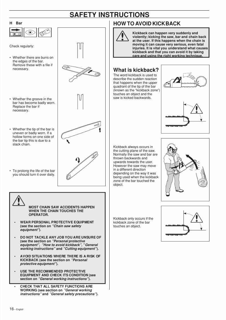
H Bar
Check regularly:
• Whether there are burrs onthe edges of the bar.Remove these with a file ifnecessary.
• Whether the groove in thebar has become badly worn.Replace the bar if
necessary.
• Whether the tip of the bar isuneven or badly worn. If ahollow forms on one side ofthe bar tip this is due to aslack chain.
• To prolong the life of the baryou should turn it over daily.
MOST CHAIN SAW ACCIDENTS HAPPENWHEN THE CHAIN TOUCHES THEOPERATOR.
• WEAR PERSONAL PROTECTIVE EQUIPMENT(see the section on ”Chain saw safety equipment” ).
• DO NOT TACKLE ANY JOB YOU ARE UNSURE OF(see the section on ”Personal protective equipment” , ”How to avoid kickback”, ”General working instructions” and ”Cutting equipment” ).
• AVOID SITUATIONS WHERE THERE IS A RISK OFKICKBACK (see the section on ”Personal protective equipment” ).
• USE THE RECOMMENDED PROTECTIVEEQUIPMENT AND CHECK ITS CONDITION (see
section on ”General working instructions” ).• CHECK THAT ALL SAFETY FUNCTIONS ARE
WORKING (see section on ”General working instructions” and ”General safety precautions” ).
SAFETY INSTRUCTIONSHOW TO AVOID KICKBACK
Kickback can happen very suddenly andviolently; kicking the saw, bar and chain backat the user. If this happens when the chain ismoving it can cause very serious, even fatalinjuries. It is vital you understand what causeskickback and that you can avoid it by taking
care and using the right working technique.
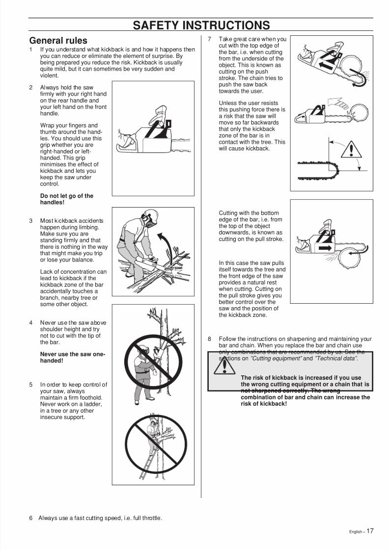
What is kickback?The word kickback is used todescribe the sudden reactionthat happens when the upperquadrant of the tip of the bar(known as the “kickback zone ”)touches an object and thesaw is kicked backwards.
Kickback always occurs inthe cutting plane of the saw.Normally the saw and bar arethrown backwards andupwards towards the user.However the saw may movein a different directiondepending on the way it wasbeing used when the kickbackzone of the bar touched theobject.
Kickback only occurs if thekickback zone of the bartouches an object.
8/7/2019 Husky 55 Manual
http://slidepdf.com/reader/full/husky-55-manual 17/36English – 17
7 Take great care when youcut with the top edge ofthe bar, i.e. when cuttingfrom the underside of theobject. This is known ascutting on the pushstroke. The chain tries topush the saw backtowards the user.
Unless the user resiststhis pushing force there isa risk that the saw willmove so far backwardsthat only the kickbackzone of the bar is incontact with the tree. Thiswill cause kickback.
Cutting with the bottomedge of the bar, i.e. fromthe top of the objectdownwards, is known ascutting on the pull stroke.
In this case the saw pullsitself towards the tree andthe front edge of the sawprovides a natural restwhen cutting. Cutting onthe pull stroke gives youbetter control over thesaw and the position ofthe kickback zone.
8 Follow the instructions on sharpening and maintaining yourbar and chain. When you replace the bar and chain useonly combinations that are recommended by us. See thesections on ”Cutting equipment” and ”Technical data”.
The risk of kickback is increased if you use
the wrong cutting equipment or a chain that isnot sharpened correctly. The wrongcombination of bar and chain can increase therisk of kickback!
General rules1 If you understand what kickback is and how it happens then
you can reduce or eliminate the element of surprise. Bybeing prepared you reduce the risk. Kickback is usuallyquite mild, but it can sometimes be very sudden andviolent.
2 Always hold the saw
firmly with your right handon the rear handle andyour left hand on the fronthandle.
Wrap your fingers andthumb around the hand-les. You should use thisgrip whether you areright-handed or left-handed. This gripminimises the effect ofkickback and lets youkeep the saw undercontrol.
Do not let go of thehandles!
3 Most kickback accidentshappen during limbing.Make sure you arestanding firmly and thatthere is nothing in the waythat might make you tripor lose your balance.
Lack of concentration canlead to kickback if thekickback zone of the baraccidentally touches abranch, nearby tree orsome other object.
4 Never use the saw aboveshoulder height and trynot to cut with the tip ofthe bar.
Never use the saw one-handed!
5 In order to keep control ofyour saw, alwaysmaintain a firm foothold.Never work on a ladder,in a tree or any otherinsecure support.
6 Always use a fast cutting speed, i.e. full throttle.
SAFETY INSTRUCTIONS
8/7/2019 Husky 55 Manual
http://slidepdf.com/reader/full/husky-55-manual 18/3618 – English
SAFETY INSTRUCTIONSGENERAL SAFETY PRECAUTIONS1 Chain saws are designed solely for cutting wood. The only
cutting equipment that can be used with this chain saw arethe combinations of bars and chains recommended in the”Technical data” section.
2 Never use a chain saw ifyou are tired, if you have
drunk alcohol, or if youare taking medication thataffects your vision, your
judgement or your co-ordination.
3 Always wear suitable protective clothing. See the sectionon ”Personal protective equipment” .
4 Never use a chain saw that has been modified in any wayfrom its original specification.
5 Never use a chain sawthat is faulty. Carry outthe regular checks,maintenance and serviceroutines described in thismanual. Somemaintenance and servicemeasures must be carriedout by trained specialists.See the section on”Maintenance” .
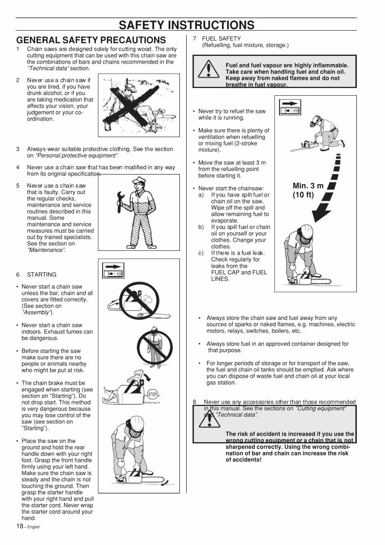
6 STARTING
• Never start a chain sawunless the bar, chain and allcovers are fitted correctly.(See section on”Assembly” ).
• Never start a chain sawindoors. Exhaust fumes canbe dangerous.
• Before starting the sawmake sure there are nopeople or animals nearbywho might be put at risk.
• The chain brake must beengaged when starting (seesection on ”Starting ”). Donot drop start. This methodis very dangerous becauseyou may lose control of thesaw (see section on”Starting ”).
• Place the saw on theground and hold the rearhandle down with your rightfoot. Grasp the front handlefirmly using your left hand.Make sure the chain saw issteady and the chain is nottouching the ground. Thengrasp the starter handlewith your right hand and pullthe starter cord. Never wrapthe starter cord around yourhand.
7 FUEL SAFETY(Refuelling, fuel mixture, storage.)
Fuel and fuel vapour are highly inflammable.Take care when handling fuel and chain oil.Keep away from naked flames and do notbreathe in fuel vapour.
• Never try to refuel the sawwhile it is running.
• Make sure there is plenty ofventilation when refuellingor mixing fuel (2-strokemixture).
• Move the saw at least 3 mfrom the refuelling pointbefore starting it.
• Never start the chainsaw:a) If you have spilt fuel orchain oil on the saw.Wipe off the spill andallow remaining fuel toevaporate.
b) If you spill fuel or chainoil on yourself or yourclothes. Change yourclothes.
c) If there is a fuel leak.Check regularly forleaks from theFUEL CAP and FUELLINES.
• Always store the chain saw and fuel away from anysources of sparks or naked flames, e.g. machines, electricmotors, relays, switches, boilers, etc.
• Always store fuel in an approved container designed forthat purpose.
• For longer periods of storage or for transport of the saw,the fuel and chain oil tanks should be emptied. Ask whereyou can dispose of waste fuel and chain oil at your localgas station.
8 Never use any accessories other than those recommendedin this manual. See the sections on ”Cutting equipment” and ”Technical data” .
The risk of accident is increased if you use thewrong cutting equipment or a chain that is notsharpened correctly. Using the wrong combi-nation of bar and chain can increase the riskof accidents!
Min. 3 m(10 ft)
8/7/2019 Husky 55 Manual
http://slidepdf.com/reader/full/husky-55-manual 19/36English – 19
SAFETY INSTRUCTIONSGENERAL WORKING INSTRUCTIONS
This section describes basic safety rules forusing a chain saw. This information is nosubstitute for professional skills andexperience. If you get into a situation whereyou feel unsafe, stop and seek expert advice(look under FORESTRY SERVICES in the
telephone directory).DO NOT ATTEMPT ANY TASK THAT YOUFEEL UNSURE OF!
Important1 Before using a chain saw you must understand the effects of
kickback and what causes it. (See the section on ”How to avoid kickback”. )
2 Before using a saw you must understand the differencebetween sawing with the top and bottom edges of the bar.(See the section on ”How to avoid kickback”. )
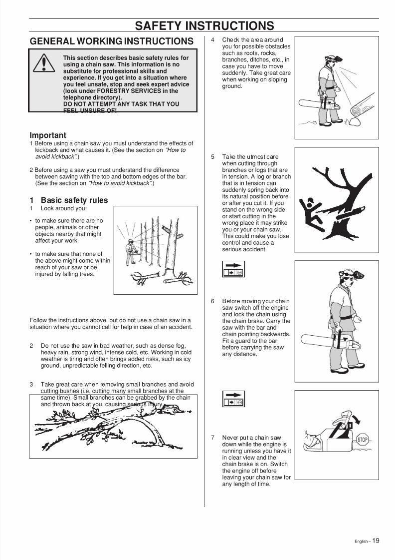
1 Basic safety rules1 Look around you:
• to make sure there are nopeople, animals or otherobjects nearby that mightaffect your work.
• to make sure that none ofthe above might come withinreach of your saw or beinjured by falling trees.
Follow the instructions above, but do not use a chain saw in asituation where you cannot call for help in case of an accident.
2 Do not use the saw in bad weather, such as dense fog,heavy rain, strong wind, intense cold, etc. Working in coldweather is tiring and often brings added risks, such as icyground, unpredictable felling direction, etc.
3 Take great care when removing small branches and avoid
cutting bushes (i.e. cutting many small branches at thesame time). Small branches can be grabbed by the chainand thrown back at you, causing serious injury.
4 Check the area aroundyou for possible obstaclessuch as roots, rocks,branches, ditches, etc., incase you have to movesuddenly. Take great carewhen working on slopingground.
5 Take the utmost carewhen cutting throughbranches or logs that arein tension. A log or branchthat is in tension cansuddenly spring back intoits natural position beforeor after you cut it. If youstand on the wrong sideor start cutting in thewrong place it may strikeyou or your chain saw.This could make you losecontrol and cause aserious accident.
6 Before moving your chainsaw switch off the engineand lock the chain usingthe chain brake. Carry thesaw with the bar andchain pointing backwards.Fit a guard to the barbefore carrying the sawany distance.
7 Never put a chain sawdown while the engine isrunning unless you have itin clear view and thechain brake is on. Switchthe engine off beforeleaving your chain saw forany length of time.
8/7/2019 Husky 55 Manual
http://slidepdf.com/reader/full/husky-55-manual 20/3620 – English
SAFETY INSTRUCTIONSTwo factors decide whether the chain will jam or the log willsplit. The first is how the log is supported and the second iswhether it is in tension.
In most cases you can avoid these problems by cutting in twostages; from the top and from the bottom of the log. You needto support the log so that it will not trap the chain or split duringcutting.
If the chain jams in the cut:STOP THE ENGINE! Don’t try to pull the sawfree. If you do you may damage the chainwhen the saw suddenly breaks free. Use alever to open up the cut and free the bar.
The following instructions describe how to handle most types ofsituation that you will be faced with when using a chain saw.
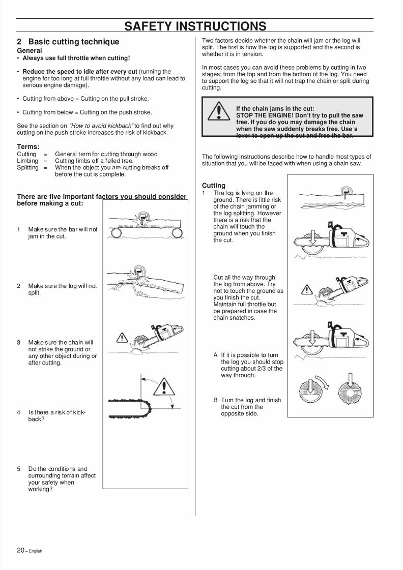
Cutting1 The log is lying on the
ground. There is little riskof the chain jamming orthe log splitting. Howeverthere is a risk that thechain will touch theground when you finishthe cut.
Cut all the way throughthe log from above. Trynot to touch the ground as
you finish the cut.Maintain full throttle butbe prepared in case thechain snatches.
A If it is possible to turnthe log you should stopcutting about 2/3 of theway through.
B Turn the log and finishthe cut from theopposite side.
2 Basic cutting techniqueGeneral• Always use full throttle when cutting!
• Reduce the speed to idle after every cut (running theengine for too long at full throttle without any load can lead toserious engine damage).
• Cutting from above = Cutting on the pull stroke.
• Cutting from below = Cutting on the push stroke.
See the section on ”How to avoid kickback” to find out whycutting on the push stroke increases the risk of kickback.
Terms:Cutting = General term for cutting through wood.Limbing = Cutting limbs off a felled tree.Splitting = When the object you are cutting breaks off
before the cut is complete.
There are five important factors you should considerbefore making a cut:
1 Make sure the bar will not jam in the cut.
2 Make sure the log will notsplit.
3 Make sure the chain willnot strike the ground orany other object during orafter cutting.
4 Is there a risk of kick-back?
5 Do the conditions andsurrounding terrain affectyour safety whenworking?
8/7/2019 Husky 55 Manual
http://slidepdf.com/reader/full/husky-55-manual 21/36English – 21
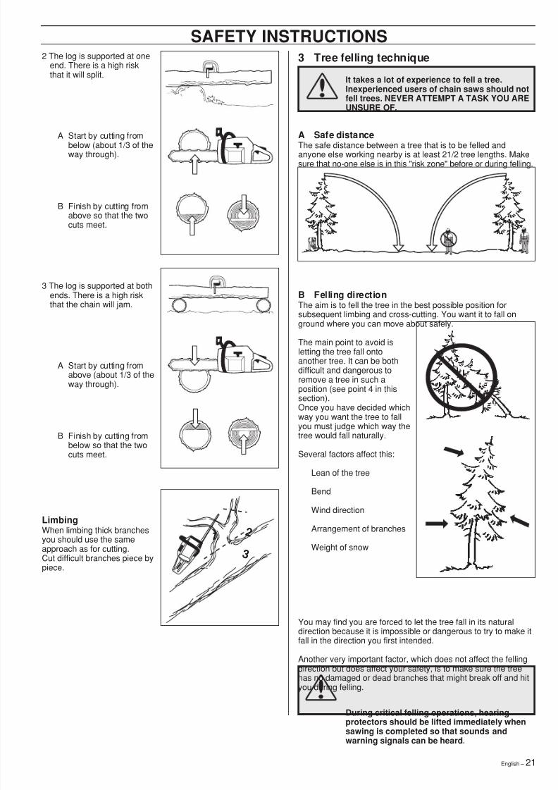
SAFETY INSTRUCTIONS2 The log is supported at one
end. There is a high riskthat it will split.
A Start by cutting frombelow (about 1/3 of theway through).
B Finish by cutting fromabove so that the twocuts meet.
3 The log is supported at bothends. There is a high riskthat the chain will jam.
A Start by cutting fromabove (about 1/3 of theway through).
B Finish by cutting frombelow so that the twocuts meet.
3 Tree felling technique
It takes a lot of experience to fell a tree.Inexperienced users of chain saws should notfell trees. NEVER ATTEMPT A TASK YOU AREUNSURE OF.
1 2
3
LimbingWhen limbing thick branchesyou should use the sameapproach as for cutting.Cut difficult branches piece bypiece.
During critical felling operations, hearingprotectors should be lifted immediately whensawing is completed so that sounds andwarning signals can be heard.
B Felling directionThe aim is to fell the tree in the best possible position forsubsequent limbing and cross-cutting. You want it to fall onground where you can move about safely.
The main point to avoid isletting the tree fall ontoanother tree. It can be bothdifficult and dangerous toremove a tree in such aposition (see point 4 in thissection).Once you have decided whichway you want the tree to fallyou must judge which way thetree would fall naturally.
Several factors affect this:
Lean of the tree
Bend
Wind direction
Arrangement of branches
Weight of snow
You may find you are forced to let the tree fall in its naturaldirection because it is impossible or dangerous to try to make itfall in the direction you first intended.
Another very important factor, which does not affect the fellingdirection but does affect your safety, is to make sure the treehas no damaged or dead branches that might break off and hityou during felling.
A Safe distanceThe safe distance between a tree that is to be felled andanyone else working nearby is at least 21/2 tree lengths. Makesure that no-one else is in this "risk zone" before or during felling.
8/7/2019 Husky 55 Manual
http://slidepdf.com/reader/full/husky-55-manual 22/3622 – English
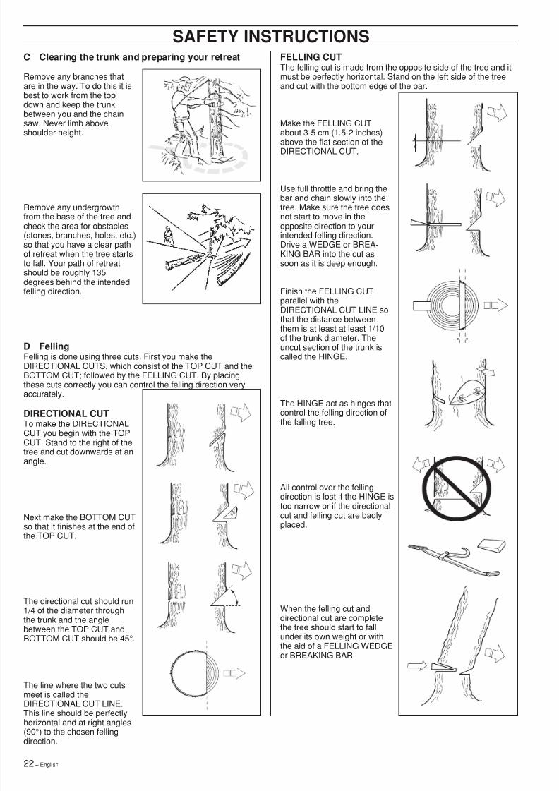
SAFETY INSTRUCTIONSFELLING CUTThe felling cut is made from the opposite side of the tree and itmust be perfectly horizontal. Stand on the left side of the treeand cut with the bottom edge of the bar.
Make the FELLING CUTabout 3-5 cm (1.5-2 inches)above the flat section of theDIRECTIONAL CUT.
Use full throttle and bring thebar and chain slowly into thetree. Make sure the tree doesnot start to move in theopposite direction to yourintended felling direction.Drive a WEDGE or BREA-KING BAR into the cut assoon as it is deep enough.
Finish the FELLING CUTparallel with theDIRECTIONAL CUT LINE sothat the distance betweenthem is at least at least 1/10of the trunk diameter. Theuncut section of the trunk iscalled the HINGE.
The HINGE act as hinges that
control the felling direction ofthe falling tree.
All control over the fellingdirection is lost if the HINGE istoo narrow or if the directionalcut and felling cut are badlyplaced.
When the felling cut anddirectional cut are completethe tree should start to fallunder its own weight or withthe aid of a FELLING WEDGEor BREAKING BAR.
C Clearing the trunk and preparing your retreat
Remove any branches thatare in the way. To do this it isbest to work from the topdown and keep the trunkbetween you and the chainsaw. Never limb aboveshoulder height.
Remove any undergrowthfrom the base of the tree andcheck the area for obstacles(stones, branches, holes, etc.)so that you have a clear pathof retreat when the tree startsto fall. Your path of retreat
should be roughly 135degrees behind the intendedfelling direction.
D FellingFelling is done using three cuts. First you make theDIRECTIONAL CUTS, which consist of the TOP CUT and theBOTTOM CUT; followed by the FELLING CUT. By placingthese cuts correctly you can control the felling direction veryaccurately.
DIRECTIONAL CUTTo make the DIRECTIONALCUT you begin with the TOPCUT. Stand to the right of thetree and cut downwards at anangle.
Next make the BOTTOM CUTso that it finishes at the end ofthe TOP CUT.
The directional cut should run1/4 of the diameter throughthe trunk and the anglebetween the TOP CUT andBOTTOM CUT should be 45 °.
The line where the two cutsmeet is called theDIRECTIONAL CUT LINE.This line should be perfectlyhorizontal and at right angles(90 °) to the chosen fellingdirection.
8/7/2019 Husky 55 Manual
http://slidepdf.com/reader/full/husky-55-manual 23/36English – 23
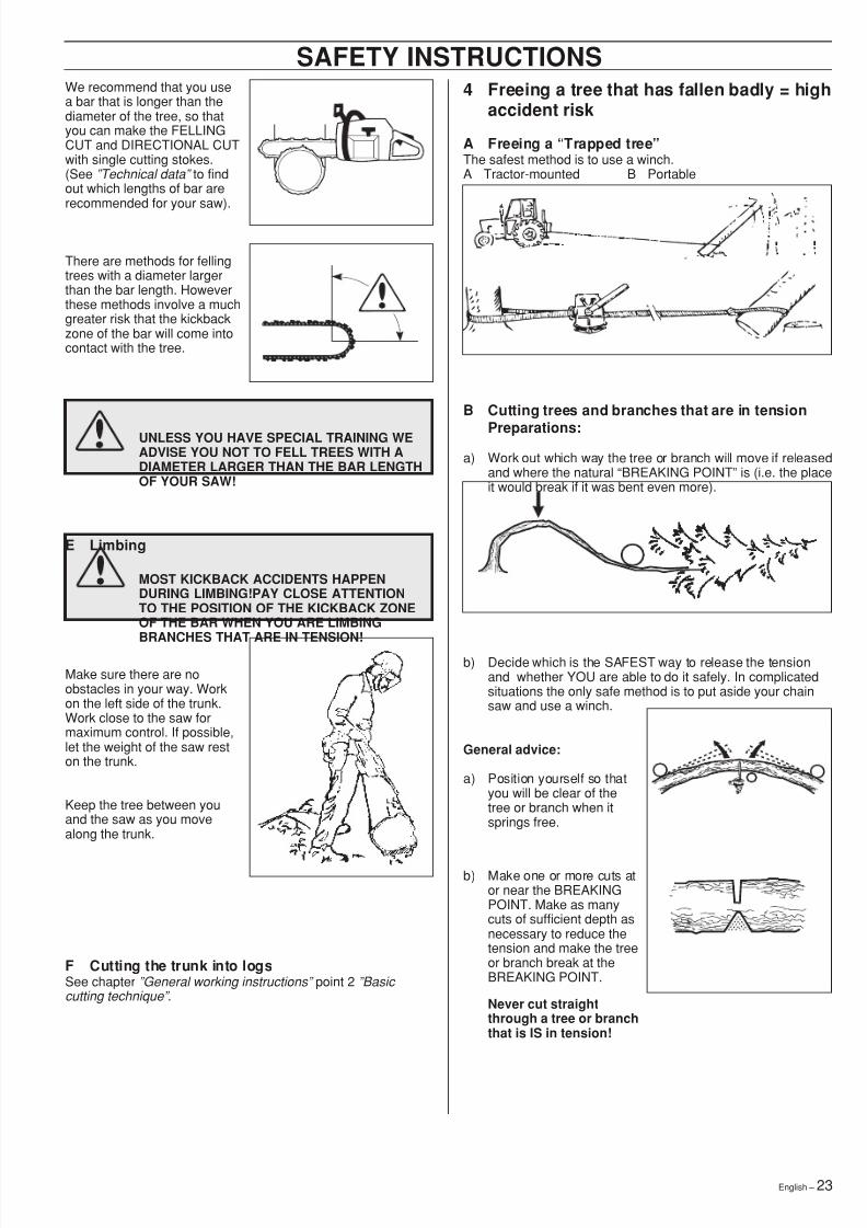
We recommend that you usea bar that is longer than thediameter of the tree, so thatyou can make the FELLINGCUT and DIRECTIONAL CUTwith single cutting stokes.(See ”Technical data” to findout which lengths of bar arerecommended for your saw).
There are methods for fellingtrees with a diameter largerthan the bar length. Howeverthese methods involve a muchgreater risk that the kickbackzone of the bar will come intocontact with the tree.
4 Freeing a tree that has fallen badly = highaccident risk
A Freeing a “Trapped tree”The safest method is to use a winch.A Tractor-mounted B Portable
B Cutting trees and branches that are in tension
Preparations:a) Work out which way the tree or branch will move if released
and where the natural “BREAKING POINT ” is (i.e. the placeit would break if it was bent even more).
b) Decide which is the SAFEST way to release the tensionand whether YOU are able to do it safely. In complicatedsituations the only safe method is to put aside your chainsaw and use a winch.
SAFETY INSTRUCTIONS
General advice:
a) Position yourself so thatyou will be clear of thetree or branch when itsprings free.
b) Make one or more cuts ator near the BREAKINGPOINT. Make as manycuts of sufficient depth asnecessary to reduce thetension and make the treeor branch break at theBREAKING POINT.
Never cut straightthrough a tree or branchthat is IS in tension!
Make sure there are noobstacles in your way. Workon the left side of the trunk.Work close to the saw formaximum control. If possible,let the weight of the saw reston the trunk.
Keep the tree between youand the saw as you movealong the trunk.
F Cutting the trunk into logsSee chapter ”General working instructions” point 2 ”Basic cutting technique” .
E Limbing
MOST KICKBACK ACCIDENTS HAPPENDURING LIMBING!PAY CLOSE ATTENTIONTO THE POSITION OF THE KICKBACK ZONEOF THE BAR WHEN YOU ARE LIMBINGBRANCHES THAT ARE IN TENSION!
UNLESS YOU HAVE SPECIAL TRAINING WEADVISE YOU NOT TO FELL TREES WITH ADIAMETER LARGER THAN THE BAR LENGTHOF YOUR SAW!
8/7/2019 Husky 55 Manual
http://slidepdf.com/reader/full/husky-55-manual 24/3624 – English
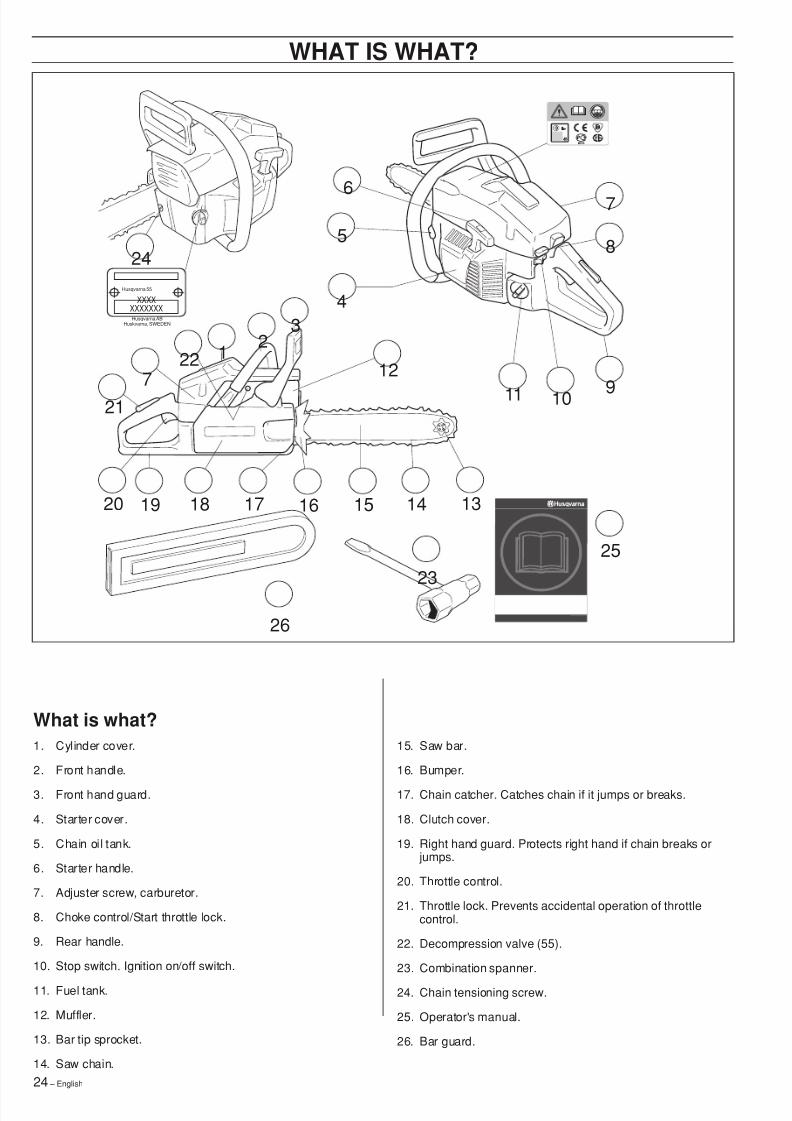
WHAT IS WHAT?
1. Cylinder cover.
2. Front handle.
3. Front hand guard.
4. Starter cover.
5. Chain oil tank.
6. Starter handle.
7. Adjuster screw, carburetor.
8. Choke control/Start throttle lock.
9. Rear handle.
10. Stop switch. Ignition on/off switch.
11. Fuel tank.
12. Muffler.
13. Bar tip sprocket.
14. Saw chain.
15. Saw bar.
16. Bumper.
17. Chain catcher. Catches chain if it jumps or breaks.
18. Clutch cover.
19. Right hand guard. Protects right hand if chain breaks or jumps.
20. Throttle control.
21. Throttle lock. Prevents accidental operation of throttlecontrol.
22. Decompression valve (55).
23. Combination spanner.
24. Chain tensioning screw.
25. Operator's manual.
26. Bar guard.
Husqvarna 55
Husqvarna ABHuskvarna, SWEDEN
XXXXXXXXXXX
13141517181920 16
23
26
25
21
227
24
213
5
4
6
12
91011
7
8
What is what?
8/7/2019 Husky 55 Manual
http://slidepdf.com/reader/full/husky-55-manual 25/36English – 25
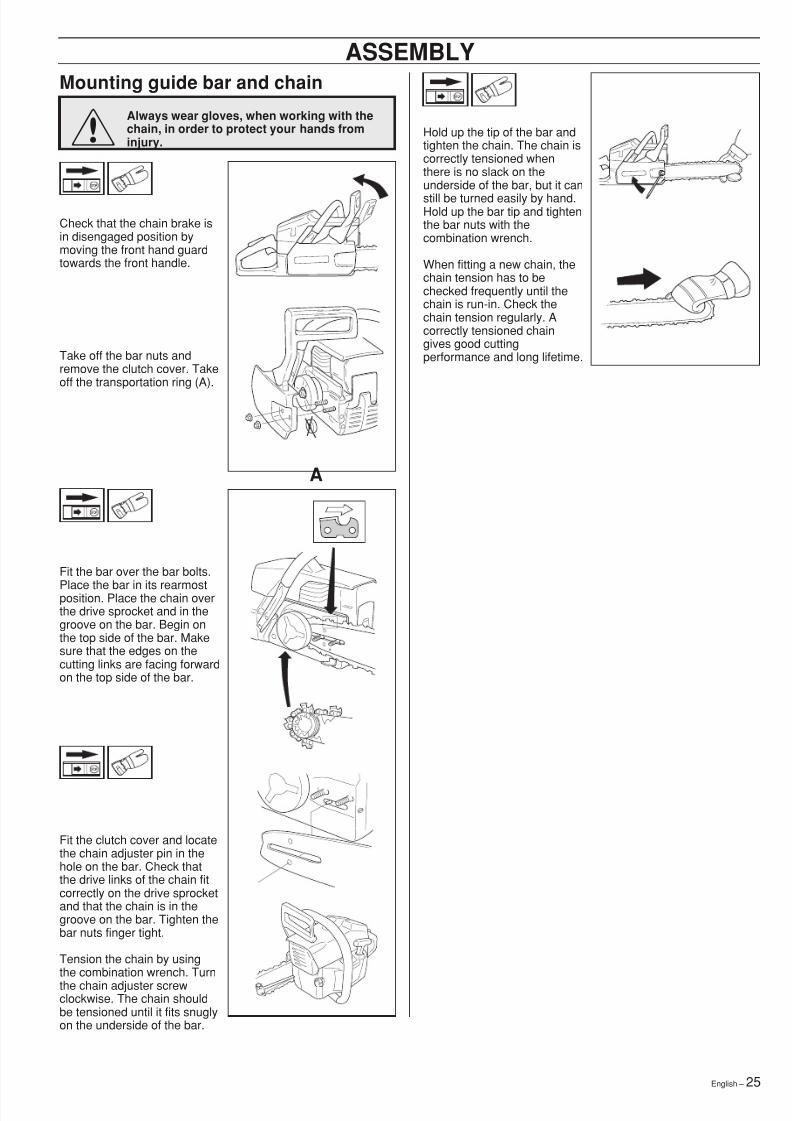
Mounting guide bar and chain
Always wear gloves, when working with thechain, in order to protect your hands frominjury.
Check that the chain brake isin disengaged position bymoving the front hand guardtowards the front handle.
Take off the bar nuts andremove the clutch cover. Takeoff the transportation ring (A).
ASSEMBLY
Hold up the tip of the bar andtighten the chain. The chain iscorrectly tensioned whenthere is no slack on theunderside of the bar, but it canstill be turned easily by hand.Hold up the bar tip and tightenthe bar nuts with thecombination wrench.
When fitting a new chain, thechain tension has to bechecked frequently until thechain is run-in. Check thechain tension regularly. Acorrectly tensioned chaingives good cuttingperformance and long lifetime.
A
!
Fit the bar over the bar bolts.
Place the bar in its rearmostposition. Place the chain overthe drive sprocket and in thegroove on the bar. Begin onthe top side of the bar. Makesure that the edges on thecutting links are facing forwardon the top side of the bar.
Fit the clutch cover and locatethe chain adjuster pin in thehole on the bar. Check thatthe drive links of the chain fitcorrectly on the drive sprocketand that the chain is in thegroove on the bar. Tighten thebar nuts finger tight.
Tension the chain by usingthe combination wrench. Turnthe chain adjuster screwclockwise. The chain shouldbe tensioned until it fits snuglyon the underside of the bar.
8/7/2019 Husky 55 Manual
http://slidepdf.com/reader/full/husky-55-manual 26/3626 – English
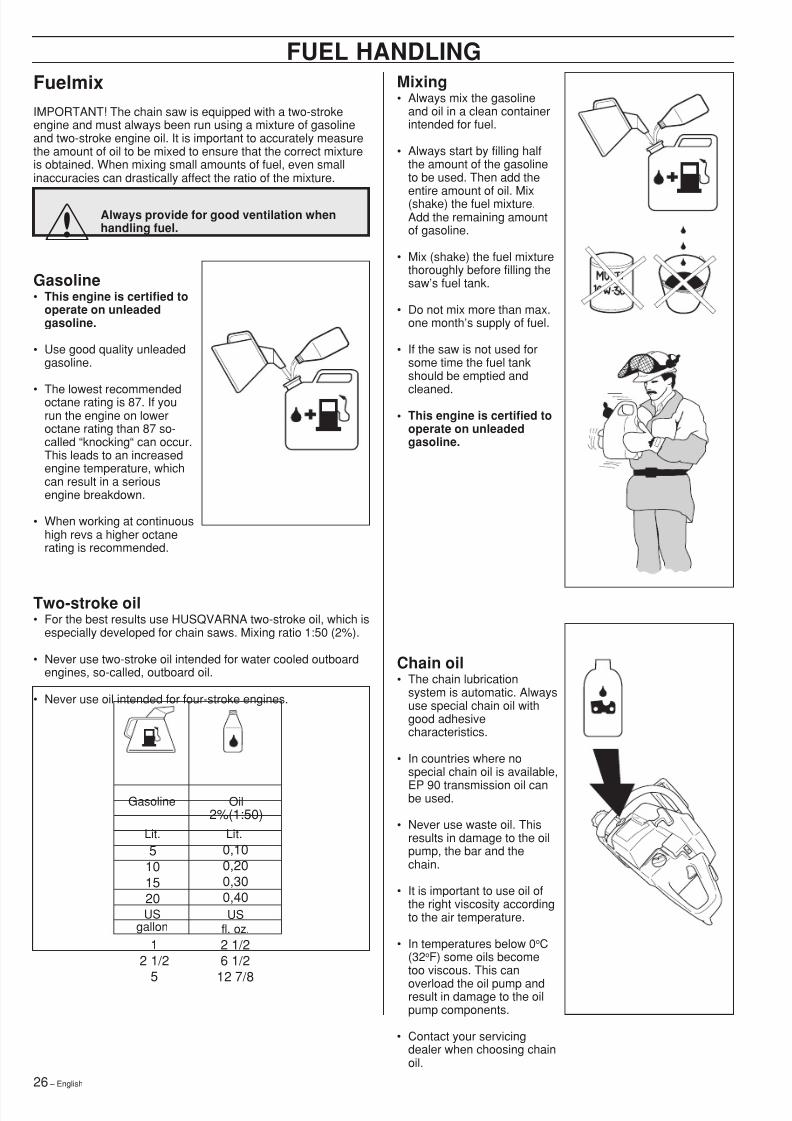
Fuelmix
Gasoline• This engine is certified to
operate on unleadedgasoline.
• Use good quality unleadedgasoline.
• The lowest recommendedoctane rating is 87. If yourun the engine on loweroctane rating than 87 so-called “knocking “ can occur.This leads to an increasedengine temperature, whichcan result in a seriousengine breakdown.
• When working at continuoushigh revs a higher octanerating is recommended.
Two-stroke oil• For the best results use HUSQVARNA two-stroke oil, which is
especially developed for chain saws. Mixing ratio 1:50 (2%).
• Never use two-stroke oil intended for water cooled outboardengines, so-called, outboard oil.
• Never use oil intended for four-stroke engines.
FUEL HANDLING
Chain oil• The chain lubrication
system is automatic. Alwaysuse special chain oil withgood adhesivecharacteristics.
• In countries where nospecial chain oil is available,
EP 90 transmission oil canbe used.
• Never use waste oil. Thisresults in damage to the oilpump, the bar and thechain.
• It is important to use oil ofthe right viscosity accordingto the air temperature.
• In temperatures below 0 oC(32 oF) some oils becometoo viscous. This canoverload the oil pump andresult in damage to the oilpump components.
• Contact your servicingdealer when choosing chainoil.
Always provide for good ventilation whenhandling fuel.!
IMPORTANT! The chain saw is equipped with a two-strokeengine and must always been run using a mixture of gasolineand two-stroke engine oil. It is important to accurately measurethe amount of oil to be mixed to ensure that the correct mixtureis obtained. When mixing small amounts of fuel, even smallinaccuracies can drastically affect the ratio of the mixture.
Mixing• Always mix the gasoline
and oil in a clean containerintended for fuel.
• Always start by filling halfthe amount of the gasolineto be used. Then add the
entire amount of oil. Mix(shake) the fuel mixture.Add the remaining amountof gasoline.
• Mix (shake) the fuel mixturethoroughly before filling thesaw ’s fuel tank.
• Do not mix more than max.one month ’s supply of fuel.
• If the saw is not used forsome time the fuel tankshould be emptied and
cleaned.• This engine is certified to
operate on unleadedgasoline.
5101520
0,100,200,300,40
Gasoline Oil2%(1:50)
12 1/2
5
2 1/26 1/2
12 7/8
USgallon
USfl. oz.
Lit. Lit.
8/7/2019 Husky 55 Manual
http://slidepdf.com/reader/full/husky-55-manual 27/36English – 27
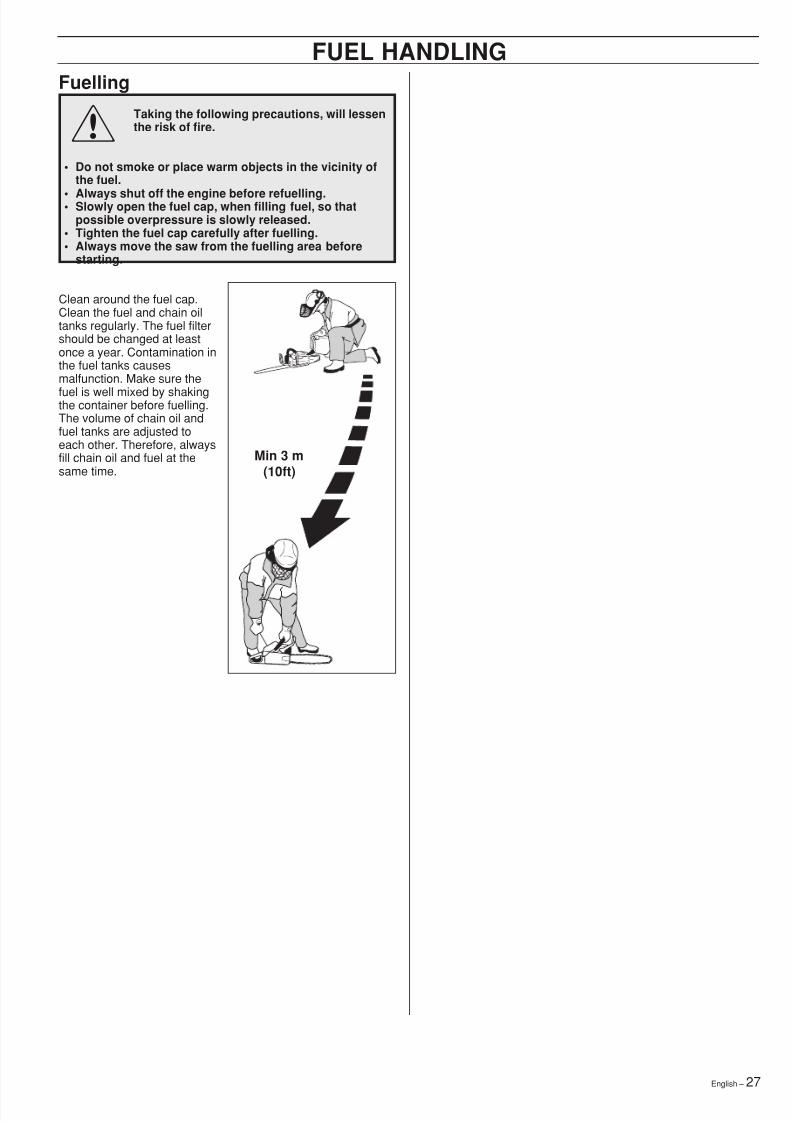
! Fuelling
Taking the following precautions, will lessenthe risk of fire.
• Do not smoke or place warm objects in the vicinity ofthe fuel.
• Always shut off the engine before refuelling.• Slowly open the fuel cap, when filling fuel, so thatpossible overpressure is slowly released.
• Tighten the fuel cap carefully after fuelling.• Always move the saw from the fuelling area before
starting.
Clean around the fuel cap.Clean the fuel and chain oiltanks regularly. The fuel filtershould be changed at leastonce a year. Contamination inthe fuel tanks causesmalfunction. Make sure the
fuel is well mixed by shakingthe container before fuelling.The volume of chain oil andfuel tanks are adjusted toeach other. Therefore, alwaysfill chain oil and fuel at thesame time.
FUEL HANDLING
Min 3 m(10ft)
8/7/2019 Husky 55 Manual
http://slidepdf.com/reader/full/husky-55-manual 28/3628 – English
! Start and stop
WARNING!
• Never start the saw engine without the bar, chain andclutch cover (chain brake) assembled - or else theclutch can come loose and cause personal injuries.
• Always move the saw away from the fueling areabefore starting.• Place the saw on clear ground and make sure that the
chain is not contacting anything. Also, make sure thatyou have a secure footing.
• Keep people and animals well away from the workingarea.
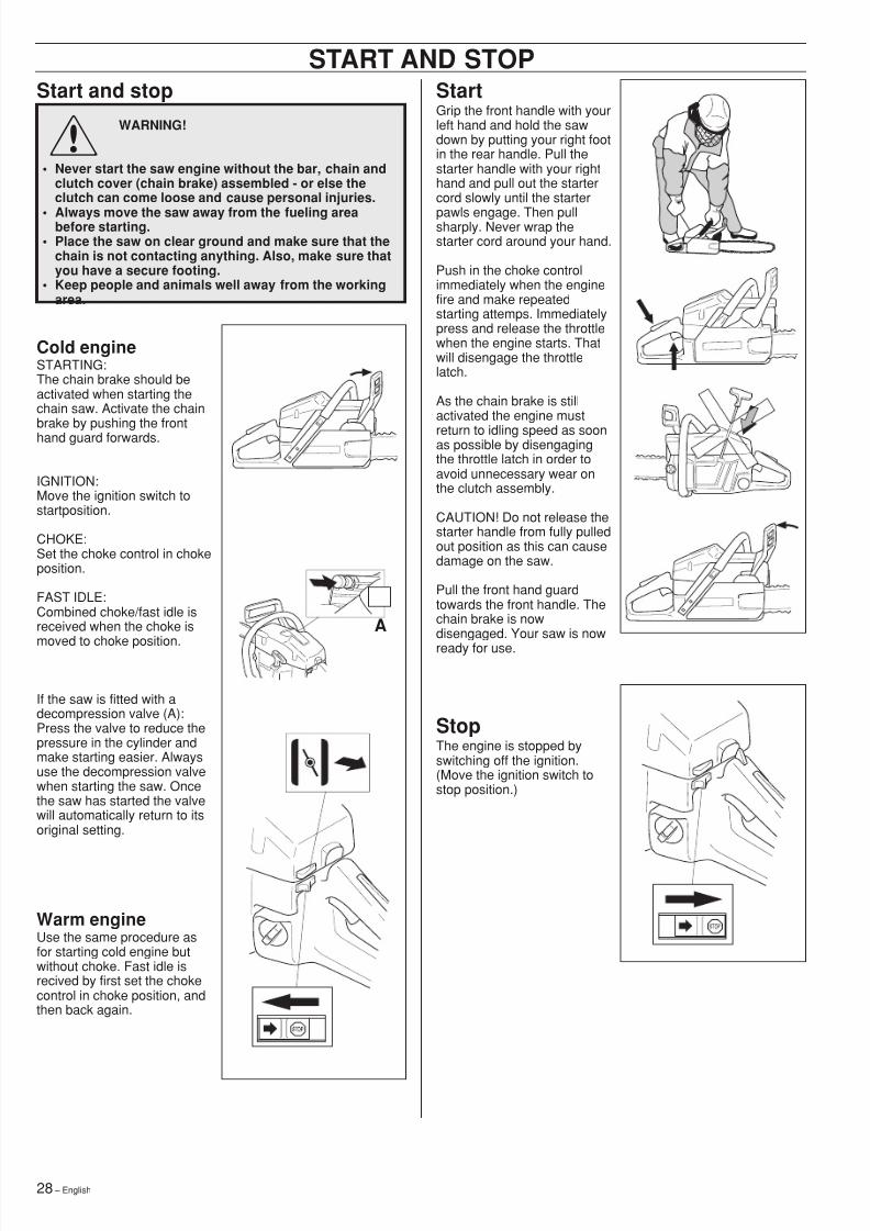
START AND STOPStartGrip the front handle with yourleft hand and hold the sawdown by putting your right footin the rear handle. Pull thestarter handle with your righthand and pull out the startercord slowly until the starter
pawls engage. Then pullsharply. Never wrap thestarter cord around your hand.
Push in the choke controlimmediately when the enginefire and make repeatedstarting attemps. Immediatelypress and release the throttlewhen the engine starts. Thatwill disengage the throttlelatch.
As the chain brake is stillactivated the engine must
return to idling speed as soonas possible by disengagingthe throttle latch in order toavoid unnecessary wear onthe clutch assembly.
CAUTION! Do not release thestarter handle from fully pulledout position as this can causedamage on the saw.
Pull the front hand guardtowards the front handle. Thechain brake is nowdisengaged. Your saw is nowready for use.
StopThe engine is stopped byswitching off the ignition.(Move the ignition switch tostop position.)
Cold engineSTARTING:The chain brake should beactivated when starting thechain saw. Activate the chainbrake by pushing the fronthand guard forwards.
IGNITION:Move the ignition switch tostartposition.
CHOKE:Set the choke control in chokeposition.
FAST IDLE:Combined choke/fast idle isreceived when the choke is
moved to choke position.
If the saw is fitted with adecompression valve (A):Press the valve to reduce thepressure in the cylinder andmake starting easier. Alwaysuse the decompression valvewhen starting the saw. Oncethe saw has started the valvewill automatically return to itsoriginal setting.
Warm engineUse the same procedure asfor starting cold engine butwithout choke. Fast idle isrecived by first set the chokecontrol in choke position, andthen back again.
A
8/7/2019 Husky 55 Manual
http://slidepdf.com/reader/full/husky-55-manual 29/36English – 29
CarburetorMAINTENANCE
Your Husqvarna product has been designed and manufacturedto specifications that reduce harmful emissions.After your unit has been run 8-10 tanks of fuel the engine hasbroken in. To ensure that your unit is at peak performance andproducing the least amount of harmful emissions after break in,have your authorized servicing dealer, who has a revolutioncounter at his disposal, to adjust your carburetor for optimum
operating conditions.
WARNING! Do not start the saw without thebar, chain and clutch cover (chain brake)assembled. If you do, the clutch might comeloose and cause severe injuries.
Functioning, Basic setting, Final setting
Operation• The carburetor governs the engine speed via the throttle. Air/
fuel are mixed in the carburetor. The air/fuel mixture isadjustable. To take advantage of the engine ’s optimal outputthe setting must be correct.
• The setting of the carburetor means that the engine isadapted to local conditions, for example, the climate, altitude,fuel and the type of 2-stroke oil.
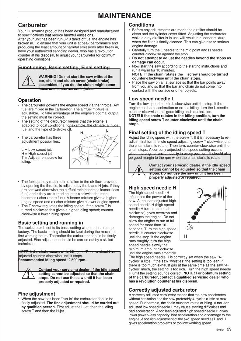
• The carburetor has threeadjustment possibilities:
L = Low speed jet.H = High speed jet.T = Adjustment screw foridling.
• The fuel quantity required in relation to the air flow, providedby opening the throttle, is adjusted by the L and H-jets. If theyare screwed clockwise the air/fuel ratio becomes leaner (lessfuel) and if they are turned counter-clockwise the ratiobecomes richer (more fuel). A leaner mixture gives a higherengine speed and a richer mixture give a lower engine speed.
• The T screw regulates the idling speed. If the screw T isturned clockwise this gives a higher idling speed; counter-clockwise a lower idling speed.
Basic setting and running inThe carburetor is set to its basic setting when test run at thefactory. The basic setting should be kept during the machine ‘sfirst working hours. Thereafter the carburetor should be finelyadjusted. Fine adjustment should be carried out by a skilledtechnician.
NOTE! If the chain rotates while idling the T screw should beadjusted counter-clockwise until it stops.Recommended idling speed: 2 500 rpm.
Low speed needle LTurn the low speed needle L clockwise until the stop. If theengine has bad acceleration or erratic idling, turn the L needlecounter-clockwise until good idling and acceleration.NOTE! If the chain rotates in the idling position, turn theidling speed screw T counter-clockwise until the chainstops.
Final setting of the idling speed TAdjust the idling speed with the screw T. If it is necessary to re-adjust, first turn the idle speed adjusting screw T clockwise, untilthe chain starts to rotate. Then turn, counter-clockwise until thechain stops. A correctly adjusted idle speed setting occurswhen the engine runs smoothly in every position. It should alsobe good margin to the rpm when the chain starts to rotate.
High speed needle HThe high speed needle Hinfluences the power of thesaw. A too lean adjusted highspeed needle H (high speedneedle H turned too muchclockwise) gives overrevs anddamages the engine. Do notallow the engine to run at fullspeed for more than 10seconds. Turn the high speedneedle H counter-clockwiseuntil the stop. If the engineruns roughly, turn the highspeed needle slowly theminimum amount clockwiseuntil the engine runs smoothly.The high speed needle H is correctly set when the saw ”4-cycles ” a little. If the saw ”whistles ” the setting is too lean. Ifthere is too much exhaust gas at the same time as the saw ”4-cycles ” much, the setting is too rich. Turn the high speed needleH until the setting sounds correct. NOTE! For optimum settingof the carburetor, contact a qualified servicing dealer whohas a revolution counter at his disposal.
Correctly adjusted carburetorA correctly adjusted carburetor means that the saw accelerateswithout hesitation and the saw preferably 4-cycles a little at maxspeed. Furthermore, the chain must not rotate at idling. A too leanadjusted low speed needle L may cause starting difficulties andbad acceleration. A too lean adjusted high speed needle H giveslower power=less capacity, bad acceleration and/or damage to theengine. A too rich adjustment of the two speed needles L and Hgives acceleration problems or too low working speed.
H
Conditions• Before any adjustments are made the air filter should be
clean and the cylinder cover fitted. Adjusting the carburetorwhile a dirty air filter is in use will result in a leaner mixturewhen the filter is finally cleaned. This can give rise to seriousengine damage.
• Carefully turn the L needle to the mid point and H needlecounter-clockwise against the stop.
• Do not attempt to adjust the needles beyond the stops asdamage can occur.• Now start the saw according to the starting instructions and
run it warm for 10 minutes.NOTE! If the chain rotates the T screw should be turnedcounter-clockwise until the chain stops.
• Place the saw on a flat surface so that the bar points awayfrom you and so that the bar and chain do not come intocontact with the surface or other objects.
Contact your servicing dealer, if the idle speedsetting cannot be adjusted so that the chainstops. Do not use the saw until it has beenproperly adjusted or repaired.
Fine adjustment• When the saw has been ”run-in ” the carburetor should be
finely adjusted. The fine adjustment should be carried outby qualified person. First adjust the L-jet, then the idlingscrew T and then the H-jet.
!
!
Contact your servicing dealer, if the idle speedsetting cannot be adjusted so that the chainstops. Do not use the saw until it has been
properly adjusted or repaired.
!
8/7/2019 Husky 55 Manual
http://slidepdf.com/reader/full/husky-55-manual 30/3630 – English
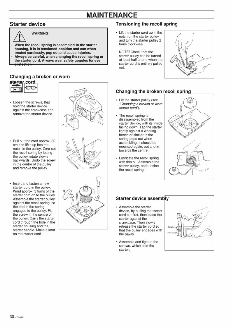
Starter deviceWARNING!
• When the recoil spring is assembled in the starterhousing, it is in tensioned position and can whentreated carelessly, pop out and cause injuries.
• Always be careful, when changing the recoil spring orthe starter cord. Always wear safety goggles for eyeprotection.
! Tensioning the recoil spring
• Lift the starter cord up in thenotch on the starter pulleyand turn the starter pulley 2turns clockwise.
NOTE! Check that the
starter pulley can be turnedat least half a turn, when thestarter cord is entirely pulledout.
Starter device assembly
• Assemble the starterdevice, by pulling the startercord out first, then place thestarter against thecrankcase. Then slowlyrelease the starter cord sothat the pulley engages withthe pawls.
• Assemble and tighten thescrews, which hold thestarter.
MAINTENANCE
Changing the broken recoil spring
• Lift the starter pulley (see"Changing a broken or worn starter cord" ).
• The recoil spring isdisassembled from thestarter device, with its insidefacing down. Tap the starterlightly against a workingbench or similar. If thespring pops out whenassembling, it should bemounted again, out and intowards the centre.
• Lubricate the recoil springwith thin oil. Assemble thestarter pulley, and tensionthe recoil spring.
Changing a broken or wornstarter cord
• Loosen the screws, thathold the starter deviceagainst the crankcase and
remove the starter device.
• Pull out the cord approx. 30cm and lift it up into thenotch in the pulley. Zero-setthe recoil spring by lettingthe pulley rotate slowlybackwards. Undo the screwin the centre of the pulleyand remove the pulley.
• Insert and fasten a newstarter cord in the pulley.Wind approx. 3 turns of thestarter cord on to the pulley.Assemble the starter pulleyagainst the recoil spring, sothe end of the springengages to the pulley. Fitthe screw in the centre ofthe pulley. Carry the startercord through the hole in thestarter housing and thestarter handle. Make a knoton the starter cord.
8/7/2019 Husky 55 Manual
http://slidepdf.com/reader/full/husky-55-manual 31/36English – 31
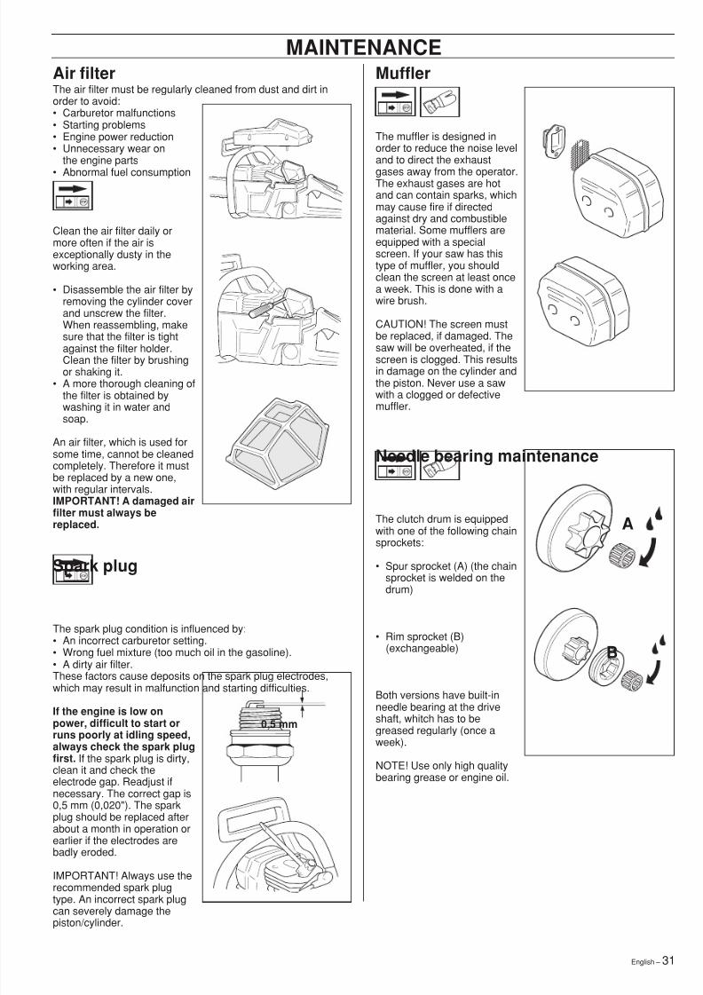
Air filterThe air filter must be regularly cleaned from dust and dirt inorder to avoid:• Carburetor malfunctions• Starting problems• Engine power reduction• Unnecessary wear on
the engine parts
• Abnormal fuel consumption
Clean the air filter daily ormore often if the air isexceptionally dusty in theworking area.
• Disassemble the air filter byremoving the cylinder coverand unscrew the filter.When reassembling, makesure that the filter is tightagainst the filter holder.Clean the filter by brushingor shaking it.
• A more thorough cleaning ofthe filter is obtained bywashing it in water andsoap.
An air filter, which is used forsome time, cannot be cleanedcompletely. Therefore it mustbe replaced by a new one,with regular intervals.IMPORTANT! A damaged airfilter must always bereplaced.
Muffler
The muffler is designed inorder to reduce the noise leveland to direct the exhaust
gases away from the operator.The exhaust gases are hotand can contain sparks, whichmay cause fire if directedagainst dry and combustiblematerial. Some mufflers areequipped with a specialscreen. If your saw has thistype of muffler, you shouldclean the screen at least oncea week. This is done with awire brush.
CAUTION! The screen mustbe replaced, if damaged. The
saw will be overheated, if thescreen is clogged. This resultsin damage on the cylinder andthe piston. Never use a sawwith a clogged or defectivemuffler.
MAINTENANCE
Spark plug
The spark plug condition is influenced by:• An incorrect carburetor setting.• Wrong fuel mixture (too much oil in the gasoline).• A dirty air filter.These factors cause deposits on the spark plug electrodes,which may result in malfunction and starting difficulties.
If the engine is low onpower, difficult to start orruns poorly at idling speed,always check the spark plugfirst. If the spark plug is dirty,clean it and check theelectrode gap. Readjust ifnecessary. The correct gap is0,5 mm (0,020"). The sparkplug should be replaced afterabout a month in operation orearlier if the electrodes arebadly eroded.
IMPORTANT! Always use therecommended spark plugtype. An incorrect spark plugcan severely damage thepiston/cylinder.
0,5 mm
A
Needle bearing maintenance
The clutch drum is equippedwith one of the following chainsprockets:
• Spur sprocket (A) (the chainsprocket is welded on thedrum)
• Rim sprocket (B)(exchangeable)
Both versions have built-inneedle bearing at the driveshaft, whitch has to begreased regularly (once aweek).
NOTE! Use only high qualitybearing grease or engine oil.
B
8/7/2019 Husky 55 Manual
http://slidepdf.com/reader/full/husky-55-manual 32/3632 – English
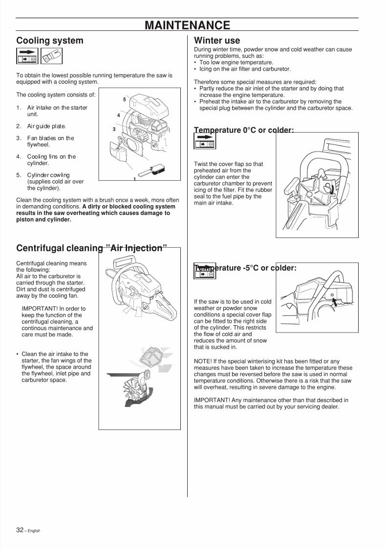
MAINTENANCECooling system
To obtain the lowest possible running temperature the saw isequipped with a cooling system.
The cooling system consists of:1. Air intake on the starter
unit.
2. Air guide plate.
3. Fan blades on theflywheel.
4. Cooling fins on thecylinder.
5. Cylinder cowling(supplies cold air overthe cylinder).
Clean the cooling system with a brush once a week, more oftenin demanding conditions. A dirty or blocked cooling systemresults in the saw overheating which causes damage topiston and cylinder.
Winter useDuring winter time, powder snow and cold weather can causerunning problems, such as:• Too low engine temperature.• Icing on the air filter and carburetor.
Therefore some special measures are required:• Partly reduce the air inlet of the starter and by doing that
increase the engine temperature.• Preheat the intake air to the carburetor by removing thespecial plug between the cylinder and the carburetor space.
1
2
5
4
3 Temperature 0 °C or colder:
Twist the cover flap so thatpreheated air from thecylinder can enter thecarburetor chamber to prevent
icing of the filter. Fit the rubberseal to the fuel pipe by themain air intake.
Temperature -5 °C or colder:
If the saw is to be used in coldweather or powder snowconditions a special cover flapcan be fitted to the right sideof the cylinder. This restrictsthe flow of cold air andreduces the amount of snowthat is sucked in.
NOTE! If the special winterising kit has been fitted or anymeasures have been taken to increase the temperature thesechanges must be reversed before the saw is used in normaltemperature conditions. Otherwise there is a risk that the sawwill overheat, resulting in severe damage to the engine.
IMPORTANT! Any maintenance other than that described inthis manual must be carried out by your servicing dealer.
Centrifugal cleaning ”Air Injection ”Centrifugal cleaning meansthe following:All air to the carburetor iscarried through the starter.Dirt and dust is centrifugedaway by the cooling fan.
IMPORTANT! In order tokeep the function of thecentrifugal cleaning, acontinous maintenance andcare must be made.
• Clean the air intake to thestarter, the fan wings of theflywheel, the space aroundthe flywheel, inlet pipe andcarburetor space.
8/7/2019 Husky 55 Manual
http://slidepdf.com/reader/full/husky-55-manual 33/36English – 33
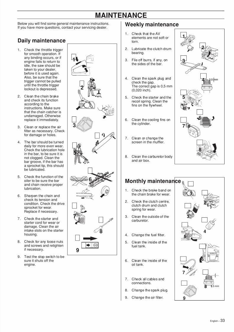
Below you will find some general maintenance instructions.If you have more questions, contact your servicing dealer. Weekly maintenance
1. Check that the AVelements are not soft ortorn.
2. Lubricate the clutch drumbearing.
3. File off burrs, if any, onthe sides of the bar.
4. Clean the spark plug andcheck the gap.The correct gap is 0,5 mm(0,020 inch).
5. Check the starter and therecoil spring. Clean thefins on the flywheel.
6. Clean the cooling fins onthe cylinder.
7. Clean or change thescreen in the muffler.
8. Clean the carburetor bodyand air box.
Monthly maintenance1. Check the brake band on
the chain brake for wear.
2. Check the clutch centre,clutch drum and clutchspring for wear.
3. Clean the outside of thecarburetor.
4. Change the fuel filter.
5. Clean the inside of thefuel tank.
6. Clean the inside of theoil tank.
7. Check all cables andconnections.
8. Change the spark plug.9. Change the air filter.
MAINTENANCE
Daily maintenance1. Check the throttle trigger
for smooth operation. If
any binding occurs, or ifengine fails to return toidle, the saw should betaken to your dealer,before it is used again.Also, be sure that thetrigger cannot be pulleduntil the throttle triggerlockout is depressed.
2. Clean the chain brakeand check its functionaccording to theinstructions. Make surethat the chain catcher is
undamaged. Otherwisereplace it immediately.
3. Clean or replace the airfilter as necessary. Checkfor damage or holes.
4. The bar should be turneddaily for more even wear.Check the lubrication holein the bar, to be sure it isnot clogged. Clean thebar groove, if the bar hasa sprocket tip, this shouldbe lubricated.
5. Check the function of theoiler to be sure the barand chain receive properlubrication.
6. Sharpen the chain andcheck its tension andcondition. Check the drivesprocket for wear.Replace if necessary.
7. Check the starter andstarter cord for wear ordamage. Clean the airintake slots on the starterhousing.
8. Check for any loose nutsand screws and retightenif necessary.
9. Test the stop switch to besure it shuts off theengine.
0,5 mm4
3
8
5
1
2
6
7
1
9
2
4
5
3
6
8
7
5
6
7
3
1
2
4
0,5 mm8
9
8/7/2019 Husky 55 Manual
http://slidepdf.com/reader/full/husky-55-manual 34/3634 – English
TECHNICAL DATA
EngineCylinder volume, cu.in/cm 3
Cylinder bore, inch/mmStroke, inch/mmIdle speed, rpmPower, kW/ rpm
Ignition systemManufactureType of ignition systemSpark plug
Electrode gap, inch/mm
Fuel and lubrication systemManufacturerCarburetor typeFuel capacity, US pint/litreOil pump capacity at8 500 rpm, ml/minOil capacity, US pint/litre
Type of oil pumpWeightWithout bar and chain, Lbs/kg
Chain/barStandard bar length, inches/cmRecommended bar lengths,inches/cmUsable cutting length, inches/cmChain speed at max. power, m/secPitch, inch/mm
Thickness of drive link, inch/mm
Number of teeth on drive sprocket
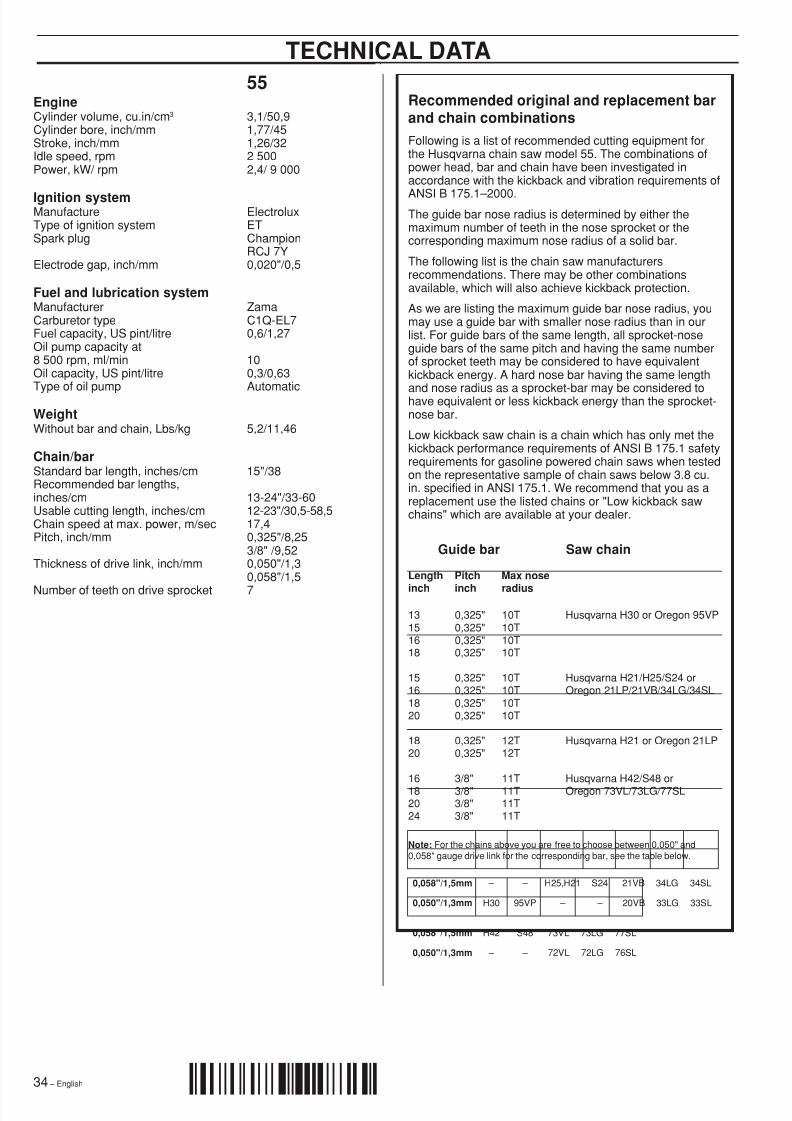
Recommended original and replacement barand chain combinationsFollowing is a list of recommended cutting equipment forthe Husqvarna chain saw model 55. The combinations ofpower head, bar and chain have been investigated inaccordance with the kickback and vibration requirements of
ANSI B 175.1 – 2000.The guide bar nose radius is determined by either themaximum number of teeth in the nose sprocket or thecorresponding maximum nose radius of a solid bar.
The following list is the chain saw manufacturersrecommendations. There may be other combinationsavailable, which will also achieve kickback protection.
As we are listing the maximum guide bar nose radius, youmay use a guide bar with smaller nose radius than in ourlist. For guide bars of the same length, all sprocket-noseguide bars of the same pitch and having the same numberof sprocket teeth may be considered to have equivalentkickback energy. A hard nose bar having the same length
and nose radius as a sprocket-bar may be considered tohave equivalent or less kickback energy than the sprocket-nose bar.
Low kickback saw chain is a chain which has only met thekickback performance requirements of ANSI B 175.1 safetyrequirements for gasoline powered chain saws when testedon the representative sample of chain saws below 3.8 cu.in. specified in ANSI 175.1. We recommend that you as areplacement use the listed chains or "Low kickback sawchains" which are available at your dealer.
Guide bar Saw chain
Length Pitch Max nose
inch inch radius
13 0,325" 10T Husqvarna H30 or Oregon 95VP15 0,325" 10T16 0,325" 10T18 0,325" 10T
15 0,325" 10T Husqvarna H21/H25/S24 or16 0,325" 10T Oregon 21LP/21VB/34LG/34SL18 0,325" 10T20 0,325" 10T
18 0,325" 12T Husqvarna H21 or Oregon 21LP20 0,325" 12T
16 3/8" 11T Husqvarna H42/S48 or18 3/8" 11T Oregon 73VL/73LG/77SL20 3/8" 11T24 3/8" 11T
0,058"/1,5mm – – H25,H21 S24 21VB 34LG 34SL
0,050"/1,3mm H30 95VP – – 20VB 33LG 33SL
0,058"/1,5mm H42 S48 73VL 73LG 77SL
0,050"/1,3mm – – 72VL 72LG 76SL
Note: For the chains above you are free to choose between 0,050" and0,058" gauge drive link for the corresponding bar, see the table below.
55
3,1/50,91,77/451,26/322 5002,4/ 9 000
ElectroluxETChampionRCJ 7Y0,020"/0,5
ZamaC1Q-EL70,6/1,27
100,3/0,63
Automatic
5,2/11,46
15"/38
13-24"/33-6012-23"/30,5-58,517,40,325"/8,253/8" /9,520,050"/1,30,058"/1,57
´+H*o¶5C¨

8/7/2019 Husky 55 Manual
http://slidepdf.com/reader/full/husky-55-manual 35/36English – 35
EMISSION CONTROL WARRANTY STATEMENT
YOUR WARRANTY RIGHTS ANDOBLIGATIONS
The EPA (The US Environmental Protection Agency),Environment Canada and Husqvarna Forest & Garden arepleased to explain the emissions control system warranty onyour 2001 and later small nonroad engine. In U.S. and
Canada, new small nonroad engines must be designed, builtand equipped to meet the federal stringent anti-smogstandards. Husqvarna Forest & Garden must warrant theemission control system on your small nonroad engine for theperiods of time listed below provided there has been noabuse, neglect or improper maintenance of your unit. Youremission control system includes Parts such as the carburetorand the ignition system.Where a warrantable condition exists, Husqvarna Forest &Garden will repair your small nonroad engine at no cost toyou. Expenses covered under warranty include diagnosis,parts and labor.
MANUFACTURER’S WARRANTY
COVERAGEThe 2001 and later small nonroad engines are warranted fortwo years. If any emission related part on your engine (aslisted above) is defective, the part will be repaired orreplaced by Husqvarna Forest & Garden.
OWNER’S WARRANTY RESPONSIBILITIESAs the small nonroad engine owner, you are responsible forthe performance of the required maintenance listed in yourOperator’s Manual. Husqvarna Forest & Garden recommendsthat you retain all receipts covering maintenance on yoursmall nonroad engine, but Husqvarna Forest & Gardencannot deny warranty solely for the lack of receipts or for yourfailure to ensure the performance of all scheduled
maintenance.As the small nonroad engine owner, you should, however, beaware that Husqvarna Forest & Garden may deny youwarranty coverage if your small nonroad engine or a part of ithas failed due to abuse, neglect, improper maintenance,unapproved modifications or the use of parts not made orapproved by the original equipment manufacturer.You are responsible for presenting your small nonroad engineto a Husqvarna Forest & Garden authorized servicing dealeras soon as a problem exists. The warranty repairs should becompleted in a reasonable amount of time, not to exceed 30days.If you have any questions regarding your warranty rights andresponsibilities, you should contact your nearest authorizedservicing dealer or call Husqvarna Forest & Garden at 1-800-
487-5963.
WARRANTY COMMENCEMENT DATEThe warranty period begins on the date small nonroad engineis delivered.
LENGTH OF COVERAGEHusqvarna Forest & Garden warrants to the initial owner andeach subsequent purchaser that the engine is free fromdefects in materials and workmanship which cause the failureof a warranted part for a period of two years.
WHAT IS COVEREDREPAIR OR REPLACEMENT OF PARTSRepair or replacement of any warranted part will be performedat no charge to the owner at an approved Husqvarna Forest &Garden servicing dealer. If you have any questions regardingyour warranty rights and responsibilities, you should contactyour nearest authorized servicing dealer or call HusqvarnaForest & Garden at 1-800-487-5963 .WARRANTY PERIODAny warranted part which is not scheduled for replacement asrequired maintenance, or which is scheduled only for regularinspection to the effect of ”repair or replace as necessary”shall be warranted for 2 years. Any warranted part which isscheduled for replacement as required maintenance shall bewarranted for the period of time up to the first scheduledreplacement point for that part.DIAGNOSISThe owner shall not be charged for diagnostic labor whichleads to the determination that a warranted part is defective, ifthe diagnostic work is performed at an approved HusqvarnaForest & Garden servicing dealer.CONSEQUENTIAL DAMAGESHusqvarna Forest & Garden may be liable for damages toother engine components caused by the failure of a warrantedpart still under warranty.
WHAT IS NOT COVEREDAll failures caused by abuse, neglect or impropermaintenance are not covered.ADD -ON OR MODIFIED PARTSThe use of add-on or modified parts can be grounds fordisallowing a warranty claim. Husqvarna Forest & Garden isnot liable to cover failures of warranted parts caused by theuse of add-on or modified parts.
HOW TO FILE A CLAIMIf you have any questions regarding your warranty rights andresponsibilities, you should contact your nearest authorizedservicing dealer or call Husqvarna Forest & Garden at1-800-487-5963 .
WHERE TO GET WARRANTY SERVICEWarranty services or repairs shall be provided at allHusqvarna Forest & Garden authorized servicing dealers.
MAINTENANCE, REPLACEMENT ANDREPAIR OF EMISSION-RELATED PARTSAny Husqvarna Forest & Garden approved replacement part
used in the performance of any warranty maintenance orrepairs on emission-related parts, will be provided withoutcharge to the owner if the part is under warranty.
EMISSION CONTROL WARRANTYPARTS LIST1. Carburetor and internal parts2. Intake pipe, airfilter holder and carburetor bolts.3. Airfilter and fuelfilter covered up to maintainance schedule.4. Ignition System
a) Spark Plug, covered up to maintenance scheduleb) Ignition Module
MAINTENANCE STATEMENTThe owner is responsible for the performance of all requiredmaintenance, as defined in the operator’s manual.

8/7/2019 Husky 55 Manual
http://slidepdf.com/reader/full/husky-55-manual 36/36