hungarian group of concrete structures · concrete structures annual technical journal hungarian...
TRANSCRIPT

CONCRETE STRUCTURESCONCRETE STRUCTURESANNUAL TECHNICAL JOURNAL
HUNGARIAN GROUP OF fibFree Example
2013Vol. 14
Géza Tassi – György L. Balázs
interaction between the old new land and the centre of the carpathian basin – from history to concrete
2
Zsigmond Dezsô – László Polgár
demanding and modern structural solutions for the nagyerdei stadium in debrecen, hungary
13
János Kozák – Béla Magyari
frc coVerings applied at two stations of the underground line no. 4 in budapest
20
Katalin Szilágyi – Adorján Borosnyói – István Zsigovics
Variability of concrete surface hardness measurement parameters
24
Orsolya Németh – Éva Lublóy – György Farkas
effects of hihg temperature on the compressiVe strength of polymer concrete
31
Viktória Vass – Éva Lublóy – László Horváth – György L. Balázs
fire design of concrete-steel composite structures
36
Mazen Al Makt – György L. Balázs
eXternal shear strengthening of precracKed rc beams with insufficient internal shear reinforcement using near surface mounted cfrp
44

CONCRETE STRUCTURES • 2013 1
CONCRETE STRUCTURESJo ur nal of the Hungarian Group of fib
Editor-in-chief:Prof. György L. Balázs
Editors:Prof. Géza Tassi
Dr. Herbert Träger
Editorial board andBoard of reviewers:
János BeluzsárAssoc. Prof. István Bódi
László CsányiDr. Béla Csí ki
Assoc. Prof. Attila Er dé lyiProf. György Far kas
Gyula KolozsiDr. Károly Ko vács
Ervin La ka tosLászló Mátyássy
László Pol gárAntonia TelekiDr. László Tóth
József Vö rösPéter Wellner
Prof. György De ákProf. Endre Dulácska
Dr. József JanzóAntónia Ki rály föl di
Dr. Jenõ KnebelProf. Péter Len keiDr. Miklós LoykóDr. Gábor Ma da rasProf. Árpád Orosz
Prof. Kálmán SzalaiProf. Géza Tassi
Dr. Ernõ TóthDr. Herbert Träger
Founded by: Hungarian Group of fibPublisher: Hungarian Group of fib(fib = International Federation for
Structural Concrete)
Editorial office: Budapest University of Technology
and Economics (BME) Department of Construction Materials
and Engineering GeologyMûegyetem rkp. 3., H-1111 Budapest
Phone: +36-1-463 4068 Fax: +36-1-463 3450
WEB http://www.fib.bme.hu
Layout and print:Csaba HalmaiNavigar Ltd.
Price: 10 EURPrinted in 1000 copies
© Hungarian Group of fibHU ISSN 2062-7904
online ISSN: 1586-0361
Cover photo:Testing of the elements of the new
Debrecen Stadium in the laboratory ofÉMI-TÜV Süd Ltd. in Szentendre,
Hungary
Sponsors:Railway Bridges Foundation, ÉMI Nonprofit Ltd., HÍD ÉPÍ TÕ Co., Holcim Hungary Co.,
MÁV Co., MSC Consulting Co., Lábatlani Vas be ton ipa ri Co., Pont-TERV Co., UVATERV Co., MÉLYÉPTERV KOMP LEX Engineering Co.,
SW Umwelttechnik Hungary Ltd., Betonmix Consulting Ltd., BVM Épelem Ltd., CAEC Ltd., Pannon Freyssinet Ltd., STA BIL PLAN Ltd., UNION PLAN Ltd.,
DCB Consulting Ltd., BME Dept. of Structural Engineering, BME Dept. of Construction Materials and Engineering Geology
CONTENT 2 Géza Tassi – György L. Balázs
iNTEraCTiON bETwEEN ThE Old NEw laNd aNd ThE CENTrE Of ThE CarpaThiaN basiN – frOm hisTOry TO CONCrETE
13 Zsigmond Dezsô – László Polgár dEmaNdiNg aNd mOdErN sTruCTural sOluTiONs fOr ThE NagyErdEi sTadium iN dEbrECEN, huNgary
20 János Kozák – Béla Magyari frC COvEriNgs appliEd aT TwO sTaTiONs Of ThE uN-dErgrOuNd liNE NO. 4 iN budapEsT
24 Katalin Szilágyi – Adorján Borosnyói – István Zsigovics variabiliTy Of CONCrETE surfaCE hardNEss mEasurEmENT paramETErs
31 Orsolya Németh – Éva Lublóy – György Farkas EffECTs Of hihg TEmpEraTurE ON ThE COmprEssivE sTrENgTh Of pOlymEr CONCrETE
36 Viktória Vass – Éva Lublóy – László Horváth – György L. Balázs firE dEsigN Of CONCrETE-sTEEl COmpOsiTE sTruCTurEs
44 Mazen Al Makt – György L. Balázs EXTErNal shEar sTrENgThENiNg Of prECraCKEd rC bEams wiTh iNsuffiCiENT iNTErNal shEar rEiNfOrCEmENT usiNg NEar surfaCE mOuNTEd Cfrp

2 2013 • CONCRETE STRUCTURES
INTERACTION BETWEEN THE OLD NEW LAND AND THE CENTRE OF THE CARPATHIAN BASIN -FROM HISTORY TO CONCRETE
Géza Tassi – György L. Balázs
Israel and Hungary have for a long time engaged in multifaceted interactions. It is the intention of this paper to highlight examples of these connections, focusing mainly on the period post 1948, following the foundation of State of Israel. The Tel Aviv Symposium 2013 of fib highlights a significant opportunity in several fields of common activity, not least being concrete and its international professional organizations.Keywords: International relations, history, culture, science, concrete
1. INTRODUCTION
1.1 The annual leading article of Concrete Structures
During the course of the life of the Hungarian Group of fib, it has become tradition that the leading article of our journal concerns itself with connections between the hosting country of the international fib convention of the year and Hungary.
2013 provides the opportunity for the fib Symposium to take place in Tel-Aviv. Accordingly, this event leads us to overview briefly the links between Israel and Hungary in history, science, culture and technology in the framework of concrete structures.
1.2 The traditional and contemporary links
Roots between these two countries run very deep and very strong. There are known cultural connections from ancient times through to the end of WW II, enough material to fill many printed volumes. Accordingly, we will focus on the time after the foundation of the modern State of Israel in 1948.
1.3 How the citizens of both countries got known about each-other
In this introduction let us flash, how the word “Hungarian” (in Hebrew hungari) appears for the first time to Israeli children, and similarly “Israeli” to young Hungarian citizens.
The answer is simple in those cases of Israeli children who have relations, neighbours and acquaintance from or near Hungary. (Let us mention here that more than 150,000, maybe 200,000 citizens of the today Israel understand Hungarian. They are immigrants of different periods or their descendents. (E. g. a relatively large number arrived from Ceauşescu’s Romania.) Others would likely meet the land of Hungary in 4th class of school while learning geography. In history they might learn about the Hungarian state in 8th or 9th year of their studies.
Alternatively young people might hear about Hungary when they hear of the Swedish diplomat, Raoul Wallenberg, who did much against the racist persecution of Jewish and as Jewish considered other people in Hungary. In sport, particularly in football, it is known among young Israelis that the famous trainer of the Israeli team, Gyula Mándi came from Hungary, where he had been a member of the champion Olympic team together with Puskás, Kocsis, Czibor and Hidegkuti. Agnes Celtic (Ágnes Keleti), the multiple olympic champion who lives in Israel, was born in Hungary and won her golden medals under the Hungarian flag.
Those children who learn music know the name of Zoltán Kodály, and if the family is fond of classical music, Ferenc Liszt and Béla Bartók. They may also be familiar with Hungarian folk tunes, operetta and Gipsy music. Children frequently hear about gastronomy, and are likely to be familiar with the Hungarian paprika (red pepper). In Hungary, because of the Judeo-Christian traditions, the great majority of the population meets the word “Izrael” for the first time in the Bible (Károli, 1936), (Bernstein, 2004) and in other religious texts. Generally, the land of Israel is studied in geography during 7th class, and in more detail in 10th class, and forms part of 9th class ancient history studies of the Near East.
The children of Hungary learn the history of WW II, the Holocaust and its consequences, then in 11th class they learn of the foundation of State of Israel in 1948.
In Hungary the territory under the British mandate until the foundation of the modern State of Israel was referred to as Palestine. Among the citizens who were educated in the Christian education system, the name ‘Holy Land’ (Szentföld) was used, and those educated in Jewish schools in Hungary referred to this land as the ‘Land of Israel’ (Erec Jiszróél).
The religion of Moses is in Hungary officially called “Izraelita”, and the citizen of Israel is called “Izraeli”. However, in everyday conversation those of the Jewish faith as well as those of Jewish ethnic origin are called “zsidó” (Jewish), and State of Israel is sometimes referred to as “Zsidó Állam” (Jewish State). It is to be emphasized that “zsidó” is not a nickname. Hungarian citizens of Jewish origin in reference to themselves officially use the term “zsidó”.
There are known to be borrowed words in use since the

CONCRETE STRUCTURES • 2013 3
Middle Ages, in majority of cases these are to be found in religion texts, e.g.: ámen, hálleluja, Tóra. There are a number words of Hebrew origin, mainly used in Hungarian slang, in the main coming not directly from Hebrew but from Yiddish, like haver (friend), jatt (hand) and many others.
2. HISTORYAs emphasized we will concentrate on the period after 1948, however, let us reflect briefly on the centuries before the establishment of modern State of Israel.
2.1 Ancient TimesIn Jerusalem, on the Mount of Olives stands the Pater Noster church dating from the 4th century (extended during the 19th century). According to tradition here Jesus taught his disciples the prayer “Pater Noster”. The prayer is posted on ceramic tablets in 60 languages, among them Hungarian and two Gipsy languages spoken in Hungary.
2.2 Middle Age
2.2.1 The Hungarian conquest
A branch of the Kazars followed the Jewish religion. Of them, a tribe, called the Kabars, joined to the Hungarian people prior to the conquest in the Carpathian Basin (896 CE). So, already before the establishment of the Hungarian Kingdom in 1001 there were countrymen who confessed the faith of Moses. It is not clear whether they had any other relationship to the Land of Israel. There is no reliable data on how numerous were the Kabars as distinct from the people who, over the next centuries, settled in Hungary arriving from different countries of the Jewish Diaspora including those originating from the ancient Jewish land. Only the observance of Jewish religion was the distinguishing feature in this population, contravening the principles of racism.
2.2.2 The Crusades
The Crusades (1096-1270) were the first time that Hungarians stepped on the land we now call Israel. These campaigns were initiated by Pope Urban IV (1195-1264) who sent his crusading army to increase European-Christian influence in the region around Jerusalem.
Hungary was involved in the Fifth Crusade (1213-1227). Pope Innocent III (1160-1216) and Pope Honorius IV (1201-1287) summoned crusading King Andrew (András) II (1166-1235) of Hungary to the side of the Austrian Duke Leopold VI (1176-1230) into the war. About 4,000 Hungarian soldiers landed on the Eastern shore of Mediterranean Sea on 23rd August 1217 and left February 1218. The short presence of Hungarians in the Crusades was largely a consequence of the illness of their king.
2.3 The early Modern Times including the 19th century
There were pilgrims who travelled across Hungary to the Holy Land from Western and Northern Europe during the centuries of the late Middle Ages. However, according to chronicles, no Hungarians were among them. Probably the first Hungarian travel diary to record a pilgrimage to the Holy Land was that of the Franciscan monk, Gábor Pécsváradi (~1460-1529), who commenced his journey in 1524 in the company of a fellow
member of his order, János Pászthódy. They spent 33 months on their pilgrimage. Pécsváradi gave an account of this in his book published in Vienna (Pécsváradi, 1520).
The Hungarian Balázs Orbán (1829-1890) travelled in many places throughout the Near East and in 1846 he travelled to Biblical destinations. Later he published his experiences under the title “Travels in the East” (in Hungarian).
In the Mea Shearim district of Jerusalem exist the so-called Hungarian Houses (Batei Ungarim) built in 1891 as a Yeshiva, for the education of Hungarian émigrés. Some decades ago the inhabitants lof these houses spoke in an archaic form of the Hungarian language. Today only the oldest people remaining there are still using this form of the language.
The central square in this area is called the Square of Hungarian Jewry.
2.4 Steps towards reviving of the Land of Israel and the roots in Hungary
2.4.1 Early fighters for State of Israel born in Hungary
Theodor Herzl (1860-1904) (Fig. 1) was born in Pest, Hungary. (His original Hungarian name is Herzl Tivadar, and his Hebrew name Benjamin Ze’ev Herzl). In Budapest today, located at the famous Dohány Street Synagogue, there is a plaque commemorating the house in which Herzl was born (Fig. 2).
Fig. 1: Theodor Herzl (Herzl Tivadar)
Fig. 2: Tablet on the native house of Herzl in Budapest

4 2013 • CONCRETE STRUCTURES
From 1879 Theodor Herzl studied law at the University of Vienna (Austria) and worked as a journalist and writer. It is not our task here to analyze all the reasons for Herzl becoming the founder of Zionism in early 20th century. No doubt he was moved by the pogroms, persecution of Jews, anti-Semite processes in different European countries. Such circumstances must have inspired Herzl to think of a new Israeli state where Jews could live without depression. His book “Old New Land” (Herzl, 1987), was published first in Vienna in 1902 (original German title “Altneuland”, in Hungarian edition “Ősújország”) as a novel. However, his thoughts were much more than a dream or fantasy.
There were other people of Hungarian origin who added much to the movement for the restoration of the Israeli state. Among them was Max Nordau (1849-1923). His native name was Südfeld Simon Miksa, who lived in Pest (today Budapest) until he reached the age of 23 years. He studied medicine and became a journalist. Nordau then lived in Germany and in France. It was a consequence of his experiences involving the Dreyfus affair that he joined and became influential in the Zionist movement, becoming very close to Herzl himself. He was engaged in medicine, philosophy and literature. Nordau is buried in Tel-Aviv.
2.4.2 Relics in Israel from WW I
In the military section of the Protestant cemetery on Mount Zion there are buried five Hungarian soldiers. They were members of an artillery group consisting of 800 soldiers of the Austro-Hungarian Army that was in 1916 sent to Palestine (at that time under Ottoman Turkish authority) to support English troops fighting against the Turks. This military unit consisted, with few exceptions, of Hungarian soldiers.
2.4.3 After WW I
The first anti-Jewish law, the s. c. Numerus Clausus, was enacted by the Hungarian parliament in 1920. Due to escalating anti-Semitism, many Hungarian citizens belonging to the Israelite denomination emigrated from Hungary with numerous groups going to the land then under British mandate, and today the State of Israel. The majority of those in the 1920’s were young specialists and students: medical doctors, engineers and artists - e.g.: engineers István (Jacov) Török, Béla (Eltan) Szívós, Mozes Sternheim and sculptor Anna (Hanna) Brünn. Till WW II a few hundreds of emigrants arrived from Hungary to the that time Palestine.
2.4.4 The time of WW II
During WW II there was no closer relation between Hungary and the people who lived in Palestine under British administration. The links were limited to persons who emigrated from Hungary
earlier. A few Hungarian speaking citizens of Romania succeeded to reach the seashore of the today Israel.
There is a memorial located between Tel-Aviv and Haifa called Sdot Yam Kibutz which was the home of the Hungarian born national hero of Israel, writer and poet Hannah Senesh (Szenes Hanna) (1921-1944) (Fig. 3). Her house, as a museum and a work of art, preserves her memory. She was born in Budapest. In 1939 she emigrated to Palestine, which at that time was under the British mandate.
In 1943 she joined the British Army and was put into action by parachute in a region close to Hungary. This was in the spring of 1944, and among many duties, she and members of the British Army undertook measures to hinder the deportation of Hungarian Jews. Hannah Senesh was arrested at the Hungarian border, she was tortured but she did not confess any detail of her mission nor of her comrades. She was condemned to death, and was executed in Budapest. Today she is remembered by a hauntingly beautiful song that she wrote: “Eli, Eli”.
In 1993 the Hungarian military jury acquitted her posthumously. In Israel, streets are named after her and her diary and poems are widely known.
There were numerous other Hungarian born soldiers living in the land known at that time as Palestine who fought in the war against Nazi Germany.
More than 70% of citizens of Hungary from among those who were considered as Jews according to anti-Semite, racist laws became victims of the persecution. Between 1939 and 19th March 1944 nearly 60,000 of them were perished in different labour camps and in 1944-45 almost 400,000 were killed in Auschwitz and other Nazi concentration camps. (These data refer to the present territory of Hungary.) (Glatz, 1999.)
2.4.5 Between WW II and 1948
From among Hungarian Holocaust survivors significant number of persons emigrated to the today Israel till 1948.
2.5 Hungary and the new State of Israel
2.5.1 First exchanges and changing circumstances between 1948 and 1988
In November 1947, after the decision of the UN, there was an optimistic expectation in progressive circles of Hungary. Hungary was not a member of the UNO in May 1948, but the Hungarian press and public opinion eagerly supported the formation of the State of Israel and the Hungarian government made diplomatic connection with Israel very soon after independence. The relations started well.
In 1956, as a consequence of the Suez crisis, the policy of the Warsaw Pact changed and intervened against Israeli interests. This was reflected in official Hungarian policy (Berei, 1962). However, a significant part of the Hungarian population expressed sympathy towards Israel. The Eichmann trial in 1961 moved the conscience of many Hungarian citizens.
May 1967 erupted in conflict between Israel and the neighbouring countries that refused the presence of UN troops at the demarcation line. In early June the access of Israel to the Red Sea at Akaba was closed, and the Israeli Army responded and took territories. An armistice was achieved in July. As a consequence of this the Hungarian government followed the dictate of the Warsaw Pact and treated Israel as an “aggressor” (Zsilinszky, 1972). After the Six Day War, under the pressure of the Warsaw Pact, Hungary withdrew diplomatic relations with Israel. The response of the Hungarian public, however, was not against Israel, and one may say, public opinion was improved after the Yom Kippur war in October 1973. During this period the commercial, scientific and cultural links were not fully seized.
In 1978 Hungary and Israel agreed to open diplomacy and 1988 re-established diplomatic ties.
Let us mention that meanwhile Israel developed and the citizens of the new state who came from Hungary, did much for the process.
Fig. 3: Hannah Senesh (Szenes Hanna)

CONCRETE STRUCTURES • 2013 5
Teddy Kollek (Kollek Tivadar) (1911-2007) was an example of Hungarian born Israeli citizens of this time who arrived in Palestine in 1935, became Mayor of Jerusalem from 1965 to 1993 and founder of the Jerusalem Foundation. He was the greatest builder of Jerusalem since ancient times. Among other initiatives, he found a way to decorate by non-figurative ornaments the holy city of the three Abrahamic religions – Christian, Muslim and Jewish – so that no creation of art should offend religiously observant inhabitants of Jerusalem. Thus Jerusalem became the largest open-air display of the avant-guard art.
2.5.2 Improvement in connections after the political changes in Hungary
Hungary arrived at the change of political system for a parliamentary democracy when the diplomatic links with Israel had already been restored. The changing relation to Israel is clearly reflected in the Hungarian public mind (s. Glatz, 2000). The diplomatic connections developed rapidly. Following is a summary of some important events.
Visits to Israel by Hungarian State Presidents in 1992, 2008 and 2012; and Prime Ministers in 1991 and 2009. The Speaker of the Parliament paid a visit in 2005. The Hungarian Minister for Foreign Affairs had official visits to Israel in 1993, 1997, 2002, 2003, 2005, 2007, 2010.
Prominent Israeli politicians also came to Hungary frequently. State Presidents travelled to Hungary in 1991 and 2004; the Speaker of the Knesset (parliament) in 1994; Ministers for International Affairs in 1994, 1995, 2001, 2005, 2010.
Important agreements were reached on the following: tourism 1988, health 1989, air transport 1989, animal-health protection 1989, culture, science and education 1990,
protection of investments 1991, science and technology 1991, avoiding double tax payments 1992, technology 1991, crime prevention 1997, economics 2006, industrial research and development 2009, and others.
In 2012 the Hungarian State President, János Áder, participated in the Wallenberg Memorial Year in Jerusalem. He was also the patron of the session in the Knesset on the occasion of the centenary of the birth of Raoul Wallenberg.
On the same day J. Áder led a consultation with President Shimon Peres and Prime Minister Benjamin Netanyahu.
President Áder also paid a visit to Yad Vashem (Fig. 4) and visited the Avenue of the Righteous Among the Nations, which also honours brave Hungarians. He cited the Talmud: “Who saves a life, saves the whole world.”
President Áder declared, “There are people (in Hungary) who behave unacceptably, … It is our task to act unhesitatingly against any act of anti-Semitism and punish it if needed.”
The State President also said, that the Holocaust is the ungradeble tragedy of the created world.
We also hope that the reasonable majority of the Hungarian population objects to anti-Israeli and anti-Semitic acts e.g. at Hungarian-Israeli friendly football match.
For the future, and with full optimism, we recall the words of President Áder, who proclaimed in Jerusalem in 2012: “There is no obstacle hindering the development of Hungarian-Israeli connections”.
3. CULTUREThere are many areas of international connections. In the case of Hungary and Israel, we may say that the strongest links are in the field of culture. In this paper it is only possible to show a few of examples, without any systematic order or striving for completeness.
Fig. 4: Hungarian State President János Áder at Yad Vashem, Jerusalem, 2012

6 2013 • CONCRETE STRUCTURES
3.1 Cultural institutions in both countries – mutual relations
In Yad Vashem memorial site and museum located in Jerusalem, a special room deals with the Hungarian experiences of the Holocaust. In the “Valley of the Communities” are included those Hungarian towns and villages from where people were deported to death camps. The Avenue of Righteous and the Wall of Honour remember some 400 Hungarians who saved Jewish citizens from this atrocity.
There is a special museum in Safed (Cfat) memorialising Jews of the Carpathian Basin. This museum presents the life and culture of Hungarian speaking Jewish people, who had a significant cultural influence over both their contemporary surroundings and present Jewry.
In the Hungarian capital the Israeli Cultural Institution is located in a building close to the Budapest State Opera. It offers events of a high standard in education and culture. An information centre and library complete the institution. There is a Hebrew language centre within the building. The Jewish Agency for Israel (Sochnut) supports this institution.
The Maccabi VAC Hungary, a sports and cultural association, organizes programs in Budapest and excursions to Israel.
There was a Hungarian-Israeli Historical Conference in the Balassi Institute in Budapest in 2011. The topic was the Hungarian/Jewish/Israeli ethnic and cultural experience over the past centuries.
3.2 LiteratureFollowing are some examples in the field of literature, sequenced by year of birth of the authors.
“My Life”, the autobiography of Golda Meir (1898-1978), former prime minister of Israel, was published in the Hungarian language in Budapest during 2000.
Arthur Köstler (1905-1983) Hungarian born author and journalist, had an adventurous life and lived in Israel for a few years. He occasionally wrote reports and other publications.
Ephraim Kishon (Kishont Ferenc) (Fig.5) (1924-2005) as a Holocaust survivor, writer and humourist, lived in Hungary until 1949. In Israel he published his papers in the Hungarian language journal “Új Kelet” (New East), and learning very quickly the Hebrew language, his writings appeared frequently in the journal “Maariv”. Soon his books were printed and gained international recognition. Dramas, cinema, various writings followed. From among his 50 books 37 were published in foreign languages. 13 books were published in Hungary.
G. György Kardos (1925-1997), Hungarian writer who survived the Nazi labour camp at Bor, moved to Israel from where he returned to Hungary in 1951. From among his many publications “Seven Days of Avraham Bogatir”, a novel taking place in 1947 in Palestine was also published in several countries. The “Palestina-Trilogia” (written in Hungarian) is noteworthy for this paper.
Aharon (Ervin) Abádi (1918-1979) writer, editor, graphic artist came to Israel in 1950. He published books and papers in Hebrew and in Hungarian, edited the weekly journal “A hét tükre” (The week’s Mirror).
3.3 MusicMusic connects our two countries in many and diverse ways - from symphonic orchestras and soloists to Klezmer bands. Following are a few examples:
In 1933 Emil Hauser (1893-1978) former first violinist of the Budapest String Quartet founded the Erez Israel Conservatory.
Ödön Pártos (Eden Partosh) (1907-1977), violinist, was pupil of Jenő Ormándy, Jenő Hubay and Zoltán Kodály in Budapest. Developing recognition in Hungary as well as internationally he moved to Tel-Aviv. Between 1938 and 1956, Partosh was the principal of the Israel Philharmonic Orchestra’s violin section.
Ilona Fehér (1901-1988), violinist, was a student of Jenő Hubay. As a Holocaust survivor she lived in different countries of Eastern Europe and emigrated to Israel in 1949. She was a concert-violinist and later her career moved to music education.
László Vincze (1904-1990) violoncellist and Ilona Krausz (1902-1998) were a well known couple both educated at the Budapest “Ferenc Liszt” Conservatory. They lived from 1935 in Tel-Aviv and founded camera ensembles playing the Hungarian composers Zoltán Kodály, Leó Weiner and others.
In 1963 a meeting of the International Council of Folk Music took place in Jerusalem. The chairman was the famous Hungarian composer and scientist Zoltán Kodály (1882-1967). Bence Szabolcsi (1899-1973), a music historian, was also present. On the occasion of this meeting the “Székelyfonó” (The spinning room), a one-act theatre peace including music from Hungarian folksongs by Zoltán Kodály, was presented with Hebrew text captions.
Born in Argentina, Daniel Barenboim (1942-), pianist and conductor, arrived in Israel in 1952 and among many other countries performed also in Hungary. For over 50 years the Hungarian public have appreciated his talents as a conductor. In 2005, at the Budapest Palace of Arts, Barenboim conducted and played the First Piano Concerto of Béla Bartók and in 2010, in the same concert hall, he gave an evening of Chopin.
The 2008 Jewish Summer Festival in Budapest featured David D’Or (1965-) and Dudu Fischer (1951-) presenting Israeli pop music.
In 2010 Orphaned Land, an Israeli metal band played in the Budapest Diesel Club along with the Finnish metal band, Amorphis.
3.4 Art The fine arts are as international as music and also offer broad connections between Israel and Hungary. Following is a small sample:
Zoltán Kluger (1896-1977) was an early photographer of the Austro-Hungarian Army. He lived in Hungary as photo-reporter and also worked abroad. He emigrated to Palestine in 1933 and established a business working for journals in constructivist and documentalist style. He also continued aireal photography.
Pál (Paul) Goldman (1900-1986) learned photography in Hungary and worked here in the 1920s. In 1940 he arrived in Haifa, having sailed on the last ship from the Black Sea. He fought in a Jewish group of the British Army. He was wounded in 1943 in North Africa, and returned to Haifa where he continued his work as a photo reporter. Later, living in Tel-Aviv, he became famous as a photo-artist, mainly through his photos of Ben Gurion.
Fig. 5: Ephraim Kishon (Kishont Ferenc)

CONCRETE STRUCTURES • 2013 7
Speaking about photography we should not overlook the internationally famous, Hungarian born, Robert Capa (Endre Ernő Friedmann 1913-1954) who did not live for long in Israel, but whose work is significant. He documented through his photographic work the first steps towards independence of the State of Israel during the period 1947-1948.
Imre Varga (1923-) Hungarian sculptor, created the Wallenberg monument in Tel-Aviv, located in the street also named after Raoul Wallenberg. Budapest also has a street bearing the name of Wallenberg, and the monument is created by Imre Varga, too (Tassi, Balázs 2012).
3.5 Theatre and cinemaIn middle of the1920s, theatre managers arrived in Tel-Aviv from Hungary and played a defining role. E.g.: Avigdor Hameiri (1890-1970) (born with the name of Feuerstein in the community of Ódávidháza, which at that time belonged to Hungary). He was an officer of the Hungarian Army in WW I. Moving to Tel Aviv he worked as a playwright and poet in Hungarian and in Hebrew and founded a theatre company. He was well acquainted in Budapest with cabaret and other theatres. He encouraged actors and stage directors to come from Europe, including the Hungarian István Irsai (Pessakh Ir-Shay) who designed in cubist style programmes, posters and scenerie.
In 2007, at the Katona József Theatre in Budapest, Lars Norén’s play, “Milhama” (War), was presented by “Habima”, the Israeli National Theatre, performed in the Hebrew language with Hungarian subtitles.
One of the most popular theatre presentations of foreign plays in 2010: the “Mikveh” by Israeli authoress Hadar Galron was performed in Budapest’s Pesti Színház (Theatre of Pest). The cast was chosen from among the best of Hungarian actresses. Previously, the play had been perform at the Festival of Contemporary Plays at the Vidám Színpad (Cheerful Stage) in Budapest, where outstanding Israeli actresses played to great applause.
Miklós Jancsó (1921-) is an internationally famous Hungarian film director and screen-writer of the 1985 film “L’aube” (Dawn). It is a French-Hungarian-Israeli movie drama. The writer was Elie Wiesel (1928-), composer Zoltán Simon (1920-1991), operator Armand Marco, editor Jean Paul Vauban. The drama is set post WW II at the time of the fight for the independence of Israel from Palestine under British rule.
4. SCIENCEThere are many fields of science where over the last 65 years significant connections have developed between Israel and Hungary. Physics, chemistry, technical sciences, economics, social sciences etc. were all fields where mutual scholarships, collaboration in research, exchange of scientists all characterized these good connections.
Many Israeli specialists who were educated in Hungary did much towards creating these good links. It is interesting, for example, the activity of the internationally famous mathematician Pál Erdős (1913-1996), whose main contact was between Hungary and Israel, but enjoyed a life that was rich with achievements all over the world.
We have place here to choose one field of science, and we select medicine and chemistry because of the Israeli Nobel Prize winners having close Hungarian links.
4.1 A few examples from medical science
There are medical doctors and chemists in Israel who were born in Hungary or coming from families of Hungarian origin. On the other hand, there are Hungarian scientists who cooperate with their Israeli colleagues. Here we try to describe those currently engaged in medical research and medical practice.
From among Israeli citizens who are Nobel Prize winners we mention those scientists who have Hungarian roots.
4.1.1 Born in Hungary Israeli Nobel Prize winner
From among the outstanding Israeli scientists originating from Hungary, we note the Nobel Prize winning biochemist Avram Hershko (Herskó Ferenc) (Fig. 6) (1937-). He and his family survived the Holocaust. They lived in Karcag, then in Budapest, and they left for Israel in 1950.
Hershko graduated as a medical doctor, and gained a PhD at the Hadassah Faculty of Medicine of the Hebrew University in Jerusalem. He was awarded the Nobel Prize (divided with Irwin Rose and Aaron Ciechanover) in 2004 for achievements in the discovery of ubiquitin-mediated protein degradation. After receiving the Nobel Prize, Hershko lectured at the Hungarian Academy of Science and afterwards, in his native city Karcag, there followed a celebration at which he received honorary citizenship of that community.
4.1.2 Israeli Nobel Prize winner having ancestors in Hungary
Daniel Shechtman (1941-) won the Nobel Prize in 2011 for the discovery of quasichrystals. He was born in Israel, but he is tied in many aspects to Hungary, from where his parents came to Israel. He had close connections to Hungarian scientists and after the great honour was conferred to him he lectured in Budapest and in Debrecen..
4.1.3 A successful example of Hungarian-Israeli cooperation
Research and manufacturing of fermented wheat germ extract, (FWGE), also known as Avemar, and Oncomar was invented by the Hungarian biochemist Máté Hídvégi (1955-) (Fig. 7) in the early 1990’s. Results indicated a very advantageous toxicity profile with significant antiproliferative and apoptosis-inducing effect on tumour cells at the pre-clinical investigations at the Semmelweis University Budapest. Based on these discoveries the process of bringing to market the extract was accelerated so that patients should receive this treatment sooner. Earlier another pharmacological invention of M. Hídvégi, a colesterine-reducing Medicago-extract, was successfully distributed in Israel. The co-workers of the Technion (Haifa) published a significant clinical research
Fig. 6: Avram Hershko (Herskó Ferenc)
Fig. 7: Máté Hídvégi

8 2013 • CONCRETE STRUCTURES
result in 1998. Therefore it was plausible that the industrial production of the new anti-cancer medicine of Máté Hídvégi should be realized in Israel.
The first commercially produced items of Avemar left the pharmaceutical producer, Hadas Natural Products (Haifa), and this product was directly distributed in Hungary.
As a result of the business connections between the Israeli pharmaceutical company, Pharmateam, and M. Hídvégi, a significant part of the cancer-research was performed in Israel. Clinical investigations were carried out with FWGE at the Faculty of Medicine of the Hebrew University Hadassah in Jerusalem; at the medical centre of the hospital Hashomer Chaim Sheba and in the Ichilov clinics of the University of Tel-Aviv. Research in immunology was performed at the centre of auto-immunology of the Hashomer hospital.
Currently research is continuing in the investigation of the effect of FWGE on patients suffering prostate cancer (Courtesy J. Vajda).
4.2 Production and education in public health
Medicine is a field of science and human endeavour where the Israeli-Hungarian links are abundant.
A hundred or so years ago a small pharmaceutical company was founded in Jerusalem. This was the cradle of Teva Pharmaceutical Industries Ltd. The firm was developed and extended its activity into more than 50 countries.
In Hungary there are two factories under the name Teva Magyarország Zrt. In Gödöllő, a continuation of the former “Humán” Hungarian plant, exists one of the largest and most up-to-date factories for the production of sterile products and products for oncology treatment. The other large factory, the former Hungarian “Biogal” factory in Debrecen (producing mainly basic material) and in Sajóbábony (which factory became the fermentation centre) also belongs to Teva. The products of these factories are distributed to many countries of the world, including Israel.
Teva made significant investments and also created a research and development centre in Hungary.One of the most significant areas of educational cooperation is in the field of medicine. The following provides some statistics
about Israeli students who studied medicine and contacting disciplines at various universities and colleges in Hungary. The language of the courses are in English.
The institutions where Israeli students studied from1998 are: Semmelweis University Budapest, Faculties of Medicine, Health Sciences, Physical Education and Sport Sciences; Faculty of Medicine of University of Szeged and that of University of Pécs; furthermore St. Stephen University Faculty of Veterinary Science.
“Premed” Preliminary course for the entrance examination is taken at the McDaniel College International Budapest and at the University of Szeged and University of Pécs.
The annual number of students completing their first year of study has increased over the period 1998 to 2012 from 54 to 167. In 2012 the full number of Israelis studying at the above mentioned institutes was 544. Of these 456 were students of medicine in Budapest, Pécs and Szeged (Courtesy A. Kádár).
5. CONCRETE
5.1 Hungarian born engineers in construction of Israel
With these examples we aim to highlight the activity of three engineers – from among many others - who were born and educated in Hungary, arrived in Israel and contributed much for the benefit of the country while preserving links to their native land.
First we would cite an example from the earlier 20th century. The tallest structure (Fig. 8.b) in Tel-Aviv was for a long time the concrete water tower. It was constructed in 1924 and designed by the Hungarian born engineer Árpád Gút (1877-1948). The Tel Aviv water tower is a protected relic.
This famous engineer graduated from the Budapest Technical University in 1901. He arrived in Tel-Aviv in 1921 and took the name Abraham Gut. He designed altogether 654 structures mostly from concrete: bridges; public, industrial and residential buildings; hydraulic structures; silos and military objects.
Earlier, in 1912 Gút designed the water tower of Siófok (Fig. 8 a), on Lake Balaton in Hungary. Let us mention here that Siófok and Netanya (Israel) are twin cities. Another significant
Fig. 8: Water tower of Siófok (a) 1912, and of Tel-Aviv (b) 1924 designed by Abraham Gut (Gút Árpád)
a) b)

CONCRETE STRUCTURES • 2013 9
structure constructed by A. Gut is the cupola of the central Synagogue in Tel-Aviv.
Gabriel Arbel (Erdélyi Gábor) (1922-2000) (Fig. 9) as a young Holocaust survivor attended the Technical University of Budapest and immediately after his studies emigrated to Israel. He worked for 30 years at the construction department of the Israeli Electric Company. In 1980 Arbel became director of the department. He was responsible for constructing large electric power stations. From among his diverse works we mention here his constructions
at Hadera (Fig. 10), (Courtesy Israel Electric Company, Mrs.
Michal Razon-Tzubery), Ashdod and Ashklon.
Arbel was active in the Association of Engineers and Architects in Israel and after his retirement in 1989 he participated in the work of HOH (Hitahdut Olei Hungaria), which organization was to help Hungarian speaking immigrants.
He visited his native country several time and nurtured connections with his Hungarian friends and colleagues.
Ve r o n i k a Z e r ( R u d a s Veronika) (1927-) the Hungarian born civil engineer (Fig.11) graduated from the Technical University of Budapest in 1950. She worked in significant and famous Hungarian design bureaus and participated in the design of large river bridges in her native country and abroad.
She arrived in Israel in 1957, commenced her work there in the design of concrete bridges for a new line of the Israel Railway. In 1958 she was employed by the Department of Public Works, bridge construction division and
provided structural designs of PC bridges and special frame structures. In 1967 under a UN scholarship she studied the CAD of bridge structures. In 1974 she gained an MSc degree at the Israel Institute of Technology, Technion, Haifa. In 1975 Veronika Zer took a study tour of several months in Berlin.
She participated in working out codes for The Standards Institution of Israel. Her office was moved to Jerusalem in 1984. From 1992 to 1994 she was deputy chief engineer of the bridge department and she was head of the design group which designed the 350 m long viaduct, the Gilo Bridge (Fig.12) located near Jerusalem. After her retirement she worked as adviser to the bridge department in the office of public works on projects such as the special viaduct at Safed (Cfat) (450 m length, 100 m spans, 70 m pier heights). She is still (2013) working in special committees of the Institute of Standardization.
Eng. Veronika Zer maintained her links to the specialists of her native country. This co-operation was highlighted in 1997 when Author2 invited her to lecture on the Gilo Bridge. This presentation was one of the highest level of lectures from foreign specialists at the Hungarian fib Group sessions. She also remains in contact with her Alma Mater, the Budapest University of Technology and Economics, which in turn awarded a Diamond Diploma to her in recognition of her long and distinguished career in civil engineering.
Veronika Zer remains in close contact with her old colleagues and friends and has also contributed in collecting valuable data for this paper.
5.2 Common activity in professional organizations
There were several occasions when Israeli and Hungarian specialists in concrete structures had the possibility to exchange experiences.
From the first step of Hungarian delegates at FIP events (1962) there were several occasions to meet Israeli colleagues.
Speaking about Israel we have to mention first the FIP Symposium Israel ’88, Jerusalem, organized by AFAI. At this event the Hungarian delegation of five engineers was headed by Gy. Fogarasi, then president of the Hungarian FIP Group. He participated in council meeting which included a full day excursion. For Hungary it was an important meeting because the FIP Council stated emphatically that the symposium in 1992 would take place in Budapest. At the closing session Gy. Fogarasi distributed a folded information about the 1992 Symposium, furthermore Author1 had the opportunity to take the floor and during words of invitation projected pictures of Budapest and some achievements of Hungarian concrete construction.
At the working session of FIP ’88, Jerusalem the paper of the Authors (Tassi, Balázs, Bódi, 1988) was presented.
Hungary organized the FIP Symposium 1992 in Budapest. Mr. J. Shimoni, President of the Israeli FIP Group acted as chairman of a working session and participated at the FIP Council meeting held on the occasion of the symposium.
In November 2002 there was an international conference in Budapest on the theme “Bond in concrete – from research to standard”. From among Israeli fib Group members D. Z. Yankelevsky and M. Jabareen presented their paper (Yankelevsky, Jabareen, 2002).
During the years of fib presidency of Author2 (2011-2012) there were active fib members from Israel: Avraham N. Dancygier, Aviad Shapira, Amir Kedar, Itai Leviatan, Avraham Pisanty, Izhak Z. Stern, David Yankelevski.
Fig. 9: Gabriel Arbel (Erdélyi Gábor)
Fig. 10: Orot Rabin site at the Hadera Power Station
Fig. 11: Veronika Zer (Rudas Veronika)

10 2013 • CONCRETE STRUCTURES
5.3 Israeli specialists and their co-operation with Hungarian experts in the frame of professional organizations
David Yitzhaki (1905-1999) (Fig. 13), the respected specialist arrived from Russia to the Land of Israel in 1925. He belonged to the first course which graduated in civil engineering at the Technion in 1928. He commenced his career in parallel: teaching, research and practical works. He carried out a wide range of designs in residential and industrial buildings, and later also in bridges. He taught all subjects of concrete technology from the fundamentals of
concrete design to prestressed concrete structures. The folded plates design was one of his favourite areas. He achieved good results in the strengthening of damaged low-rise buildings, applying post-tensioning to the walls. He investigated the punching phenomena on flat slabs. This work was published by ACI in 1966 and was acknowledged internationally.
David Yitzhaki was the first full professor of structural engineering at the Technion, whose Alma Mater was this institute. He retired in 1969, but he continued teaching and working in research for a long time afterwards.
Thanks to international professional associations (in this case IABSE) relatively early contact between Israeli and Hungarian concrete specialists was established. Good relation with D. Yitzhaki commenced in 1960 at the IABSE congress. He held discussions with the head of the Hungarian delegation, Prof. K. Széchy and other delegates, principally Gy. Márkus and Gy. Deák, both of whom had special interest in the activities of D. Yitzhaki. Author1, together with Á. Apáthy, was fortunate to spend a longer time with the Israeli professor. (Tassi, Balázs, 2012).
Author1 received the book written by Israeli professor (Yitzhaki, 1958), and it became an educational resource for the students of the Technical University of Budapest, who had diploma work tasks connected with folded plates and shells. 28 years later Author1 was invited to give lecture at Technion (Haifa) and was pleasantly surprised to find Prof. Yitzhaki among the audience, and there followed a pleasant discussion with him after the lecture.
Jacob Shimoni (1928-1996) (Fig. 14), the outstanding person of Israeli concrete construction came to Israel from Yugoslavia in 1941. He was an internationally respected specialist, an expert in RC and PC, highway and railway bridges, long span marine and industrial structures.
After graduat ing from the Technion in 1952, he undertook work in Israel and later at an engineering consulting bureau in the Netherlands. He was subsequently appointed as
technical director of Israel Freyssinet Co. Shimoni transmitted to younger generations, over a period of several years in his role as associate professor for prestressed concrete, his vast knowledge of this subject. Jacob Shimoni became in 1963 a founding partner of Yaron-Shimoni-Shacham Consulting Ltd in Tel-Aviv. This firm projected more than 300 bridges in Israel. Shimoni introduced the first segmental concrete railway bridge with a length of 188 m, 33 m tall, supports with a main span 42 m built in 1975 in the southern region of the country. (Courtesy Shirley Isseroff, Yaron-Shimoni-Shacham Ltd.)
Jacob Shimoni was involved in a wide range of activity in several Israeli and international professional associations, such as PCI, ACI, IABSE, etc. As a leading person of Israeli FIP Group he played an important role in one of the ancestors of fib. He contributed to the FIP Symposium in Jerusalem in 1988 and represented Israel at the FIP Symposium in Budapest in 1992. He was awarded the FIP Medal (1988) and received acknowledgement from the Israeli Society of Civil Engineers.
J. Shimoni nurtured many good relationships, - among other links - with the Hungarian Group of FIP. As described in Point 5.2. it was to his merit that Israeli-Hungarian connections gained momentum during the political changes in Hungary. He contributed significantly to this restoration of cooperation between these two countries. This was highlighted at his visit to Hungary in 1992.
Avraham Pisanty (1936-) (Fig.15) arrived in Israel from Bulgaria in 1949. He achieved the BSc degree in 1961, MSc 1965 and DSc 1972 at the Technion. He served many years in the Israeli Army as sr. consultant. From 1961 to 1968 he worked in a civil engineering practice, and from 1968 to 2004 at the Technion, where he was recipient of the Alexander Humboldt stipend in 1974-75. He was visiting research fellow in Waterloo between 1984 and 1986, in Vancouver 1995, and in Calgary 2000. He is fellow of ASCE, fib and IABSE, a member of
Fig. 12: The Gilo-Bridge
Fig. 13: David Yitzhaki
Fig. 14: Jacob Shimoni

CONCRETE STRUCTURES • 2013 11
Fig. 17: Reception at the Budapest University of Technology and Economics for new graduated Israeli students and their relations.
Israeli Association of Architects and Engineers since 1965.
A . P i s a n t y t a u g h t b o t h undergraduate and graduate students most disciplines of concrete design, included earthquake engineering. His fields of research were mainly in non-reinforced concrete walls, linear and non-linear analysis, ductility, punching, multi-story structures, concrete slabs, shear and flexural resistance of PC hollow core slabs. He was member of several code committees, and chairman of seven
committees for many years.Prof. Pisanty was member then head of Israeli delegation
of CEB (later fib) from 1983 till 2003. He was member of WG of ductility and structural design models. He published much in various fields of concrete design, including his book on reinforced concrete principles. He was occasionally consultant to the Ministries of Defence, Labour, Housing, and to major construction companies such as EL AL Airlines, and was an expert witness of courts.
Prof. Pisanty had many connections to Hungarian colleagues. In CEB commissions, task groups and plenary sessions he became acquainted with his Hungarian colleagues, among them B. Goschy, P. Lenkei and Author1. The latter hosted him in Budapest and held discussions on collaboration. Further discussions were had at the fib Symposium 2000 held in USA, at which both Authors were present. Prof. Pisanty invited Author1 to lecture at the Technion in September 1988.
Avraham Dancygier (1956-) (Fig. 16) is a leading structural engineer in Israel, associate professor at Faculty of Civil and Environmental Engineering, Technion. He achieved the BSc degree at the Technion, Haifa in 1979; and MSc in 1985, and he gained his PhD degree at Northwestern University, USA in 1991. From 1979 to 1987 he worked at the Civil Engineering Division of I.A.F. He was active in project management and the design of
complex civil, military and protective structures. He is member of many commissions in field of codes, works in advisory committees, is member ASCE, ACI, IAEA.
Avraham Dancygier is active in international professional organizations, and participated in the organizing committee of 2013 fib Symposium in Tel-Aviv. He helped both Authors of this paper providing valuable material for our journal.
5.4 Education in Civil EngineeringIt was a very important and interesting feature of Hungarian-Israeli cooperation that many Israeli students came to learn at the Budapest University of Technology and Economics (BME).
After 1991 more than 130 Israeli young people attended BME courses at four faculties.
At the Civil Engineering Faculty in years 1991-2009 close 60 Israeli citizens were our students. Almost all of these young people studied at major of Structural Engineering, and they were all talented and diligent students. For graduation as BSc the great majority of those made a diploma work with the task of designing a concrete structure of high level. Let us mention
Fig. 15: Avraham Pisanty
that at the Faculty of Architecture 66 Israeli students attended the courses, including concrete structures.
There was in all cases a celebration in good atmosphere when graduates received their diploma, and frequently Israeli relations came to take part at these events (Cortesy L. Kunsági, photo J. Philip) (Fig. 17).
We hope that our Israeli graduates serve well the building industry of their homeland.
6. CONCLUSIONSAs mentioned, our aim was to show the connections of Hungary and the organizing country, Israel, of the fib Symposium Tel-Aviv 2013. Due to the events of the 19th and 20th centuries in Hungary it is a consequence that many Hungarian citizens have left for Israel. This way numerous Hungarian born people contributed in development of Israel in field of art, literature, science, commerce and technology, also in concrete.
The heritage and the present cooperation create an advantageous base to the good relation between the two countries.
The world politics tried to influence for a period to disturb the good links which were built up at the time of the creation of the modern State of Israel in 1948. After the re-establishment of the normal diplomatic connections the relation became better quickly. The mutual effort in the last decades increased to develop the cooperation. Sure, the Israeli citizens – among them who understand Hungarian – accept with pleasure the approaching of the two lands. In Hungary those who have an attitude because of religion or tradition aspects together with their other countrymen acknowledge the good relations between the states. The believers following the New Testament are fond of the knowledge that the holy places of Christianity are attainable, and – as Israeli hospitality demonstrates - all Hungarian visitors are welcome in Israel.
The Hungarian and Israeli specialists in concrete did their best even till now. It is advisable that concrete engineers of the two countries should improve the common work in research, development, education and practical construction. The international professional organizations, first of all fib, as well as the agreements between the two governmental authorities give a good frame to this work.
The fib Symposium Tel-Aviv 2013, as we hope, will continue the good achievements of our international federation.
In the spirit of all these we wish much success to the Israeli organizers of the symposium to the benefit of all participants arriving to Tel-Aviv from all continents and all concrete engineers of the world.
Fig. 16: Avraham Dancygier

12 2013 • CONCRETE STRUCTURES
7. ACKNOWLEDGEMENTSThe Authors express their thanks to all friends and colleagues who contributed to this paper. We may say the traditional gratitude is due to Mrs. K. Haworth-Litvai for correction of the text of this leading article.
Thanks to the distinguished persons who are mentioned in the text for their courtesy supplying facts and data published in this paper.
8. REFERENCESBerei, A. (Editor) (1962): “New Hungarian Encyclopaedia”, Vol. 3. (In
Hungarian), Akadémiai Kiadó, BudapestBernstein, B. (translator) (2004): “The Torah, Five Books of Moses” (In
Hungarian), reprint, MAZSIHISZ, BudapestGlatz, F. (President of Editorial Board) (1999): “Great Hungarian
Encyclopaedia”, Vol. 9. Magyar Nagylexikon Kiadó, Budapest.Glatz, F. (President of Editorial Board) (2000): “Great Hungarian
Encyclopaedia”, Vol. 10, Magyar Nagylexikon Kiadó, Budapest.Herzl, T. (1987): “Old New Land” (Translated by L. Levensohn from the
original volume “Altneuland” 1902), Markus Wiener Publisher, Princeton NJ.
Károli, G. (translator) (1936): “The holy Bible”, (In Hungarian), Brit és külföldi Biblia társulat, Budapest.
Mihailich, Gy., Haviár, Gy. (1966): “Beginning and the first achievements of reinforced concrete construction in Hungary”, (In Hungarian), Akadémiai Kiadó, Budapest.
Pécsváradi, G. (1520): “Compendiosa quaedam nec – lectu iocunda descriptio urbis Hierusalem” Vienna (in 42 letters)
Tassi, G., Balázs, L. G., (2012): ”Swedes and Hungarians in the whirlwind of time – from history to concrete”, Concrete Structures, pp. 2-5.
Tassi, G., Balázs, L. G., Bódi, I. (1988): “Bond properties of prestressing strands” Proceedings of the F.I.P. Symposium, Jerusalem, 1988. FIP-AFAI, pp. 121-128.
Yankelevsky, D. Z., Jabareen, M. (2002): “2-D aspects in modelling of tension stiffening in reinforced concrete”, Bond in Concrete, from research to standards, fib Hungarian Group, Budapest, (Editors G. L. Balázs, P. Bartos, J. Cairns, A. Borosnyói), pp. 1-8.
Yitzhaki D. (1958): „The design of prismatic and cylindrical shell roofs”. Haifa Science Publishers
Zsilinszky, S. (Editor) (1972): “New Hungarian Encyclopaedia” Vol. VII (completion), Akadémiai Kiadó, Budapest.
Prof. Géza Tassi (1925), Civil Engineer, PhD, D.Sc., FIP medalist, lifetime honorary president of Hungarian Group of fib, awarded at the first congress of fib, holder of Palotás László award (fib Hungarian Group), owner of Diamond Diploma of Budapest University of Technology and Economics (BME), owner of Golden Ring of BME. He is active (semi retired) at the Department of Structural Engineering of BME. Main field of interest: prestressed concrete, bridges and other structures.
Prof. György L. Balázs (1958), Civil Engineer, PhD, Dr.-habil., professor of structural engineering, head of Department of Construction Materials and Engineering Geology at the Budapest University of Technology and Economics (BME). His main fields of activities are experimental investigation and modeling of RC, PC, FRC structures, HSC, fire resistance of concrete. He is chairman of several commissions and task groups of fib. He is president of Hungarian Group of fib, editor-in-chief of the journal Concrete Structures. He was elected as President of fib at the Washington fib Congress and performed this function in 2011-2012, and accordingly he is present time immediate past president of the international organization.
CONCRETE STRUCTURES • 2013 13
DemanDing anD moDern Structural SolutionS for the nagyerDei StaDium in Debrecen, hungary
Zsigmond Dezsô – László Polgár
The first of the fourth generation stadiums in the country is being built in the Nagyerdő [Big Forest] city part of Debrecen, which, due to the high standard construction, is built using numerous modern and unique structure solutions. Its design was rendered more difficult by the predefined short construction time and the allowance for a restricted cost level. Due to all these the only possible way of construction was a full scale precasting based on new technologies. With its special design and the production technological and development problems raised, the uncommon, i.e. in the Hungarian practice previously unused solutions, such as, the arched, plane bottom-side grandstand elements, the almost 20 m long prestressed reinforced concrete circular columns, the covered nodes, can be, if implemented in practice, a veritable proof of the high standard of Hungarian reinforced concrete precasting.
Keywords: stadium, precast reinforced concrete structure, arched grandstand element, prestressed circular column
1. INTRODUCTIONThe Nagyerdő [Big Forest] area enclosing the Northern side of Debrecen is one of the oldest protected areas in Hungary and Europe. A small part of it, but nevertheless an organic part of the city, is the Nagyerdei Park with the university, the thermal and open-air bath, the teaching hospitals, the zoo and the amusement park. The mellowed by age Nagyerdei Stadion [Big Forest Stadium] openned its gates amidst this surrounding in 1934.
In recent years it became a clear-cut demand to rebuild the existing deteriorated stadium and through reconstruction to realise a modern building. However a basic requirement was that the new stadium served not only the world of football, but by its services and events, to be also at the disposal of city inhabitants paying a recreation visit to Nagyerdő all across the year.
Therefore the task was to design a multifunctional, self-maintaining, modern establishement that fits into its surrounding. Thus the place of the legendary Nagyerdei Stadion shall be taken by an establishment satisfying all needs, accompanied, as these modern times require, also by business and entertainment industry investments and by the rehabilitation of its environment. It is thus understandable that all these are combined with a fastidiousness uncommon for stadiums, which is to fall in line with by the mostly visible structures.
2. PRELIMINARIES
2.1 Client, constructorsInvestor: Nagyerdei Stadion Rekonstrukciós Kft.Architectural design: Péter Bordás Structure design: Zsigmond Dezső
2.2 Design basicsUEFA ranking: IV. categoryFootball field size: 68x105 mTotal number of spectators: 20.020 peopleConstructed floor space: 28.700 sqm.Number of media seats: 150 peoplePlaces for radio and TV-reporters: 50 pcsVIP- area: 1.500 m2
Number of SKY-boxes: 26 pcs
2.3 Location, space connectionsThe stadium building is located in the heart of the Nagyerdei Park in the focus area marked by the promenade. The transparent shell structure makes it possible for the stadium to integrate into the park, to become part of it. The sight of green leaves can be enjoyed from every part of the stadium. This relationship between the park and the arena makes the Nagyerdei Stadion unparallel also on an international level.
The here and there floating and lapping pedestrian bridge system bordering on the smaller triangle area of the park hosting the stadium, is connected by its tentacles and embrasing grasp to the park, to nature. Their functional affinity is ensured by the placement of spare time areas, i.e. the playground, the BMX bycicle ground, picnic conveyances, walk pathes, cafés, restaurants, etc.
Keeping the mass of spectators away from the park level and its natural resources, the pavement that is lead in the air offers city people a possibility to lift-off from the ground, to observe when walking, the fauna of the Nagyerdő from an unusual proximity at the level of leafy crowns. Beyond the visual experience offered the suspended walking system protects the service units that are independant from football matches, the clients of premises serving for other spare time activities from the masses coming to the matches. The 1100 m long race

14 2013 • CONCRETE STRUCTURES
track at the edge of the walkway swaying both vertically and horizontally offers under modern conditions a special running or jogging experience to the lovers of this mass sport (Fig. 1).
Beside its external connections an important part is the asymmetrical grandstand, which ensures the reaching of a maximum number of spectators by making the most of the given space. Beyond its functional simplicity the one-tier seating strengthens the feeling of collective affinity. Due to the light structural and rational functional design, the inner layout is clear, transparent and comprehensible.
3. STRUCTURE CHOICE, DESIGNER WORK
As in every case the design of the building strived to create a safe and optimal balance of the different conditions. Complying with the requirements of durability and rentability, a primary aspect of the stadium, alongside functional and aesthetic requirements, was the consideration of a particularly short construction time. This can be complied with only by an increasing interference and unity of the different building structures. Each given independent building structure is part and parcel of the entire bulding, and although they usually also function independently, they are always part of a system in which they are in close interaction with the other elements of the system. Therefore design aimed at a joint consideration, respectively harmonisation of the building structures of the complete establishment, at a homogenous design of a “whole”. This was done in this case by a weighted consideration of the defined criteria, such as FUNCTION, AESTHETICS, SPEED, and by a continuous and careful consideration of the TECHNOLOGICAL POSSIBILITIES.
The design influencing the unity of the complete establishment, was thus the joint task of the architect and the structure designer. Contrary to many great stadiums world wide the drawings of the Nagyerdei Stadion do not strive to
create a self contained architectural sight, but to blend the huge mass of the establishment, both in form and function, into its surrounding. For this purpose the framework of the building, respectively the grandstand was constructed following the principles of functionality and economic efficiency. According to all these when deciding on the structure of the building, besides employing a maximum of precasting we pushed a demanding covered node design and a relatively scarcely used application of flat bottom surface grandstand elements into the limelight.
Design had to pay attention to the economically efficient and dimension precise precasting of threedimensional structures and to the difficulties of the in-situ construction and erection. This is why during the design process we coordinated step-by-step the employed structures and their shuttering, concreting, reinforcement and tensioning technologies. The developed concepts, respectively structural elements were tested, respectively validated by laboratory model trials.
4. STRUCTURE DESCRIPTIONThe building block of the stadium is divided into four separate dilatation units, each with an independent load bearing structure. The easthern longitudinal side grandstand has a ground floor + two storey structure and a roof structure supported by steel bar columns starting from the arrival level. The wing built together with the northern grandstand has a similar frame structure, however it is complemented by further two, or in some parts by three storeys (Fig. 2). The southern and shorter northern building parts are designed with heights and structures providing for a transition between the two longitudinal sides.
As regards the frame structure of the building, it is made up of precast reinforced concrete elements supported by precast reinforced concrete articulated “linkage” column/beam frames placed in general at each 7,45 m. At the grandstand frames
Fig. 1: Visualisation of the planned stadium

CONCRETE STRUCTURES • 2013 15
support precast reinforced concrete elements that fit into each other and have a stepped upper part. The intermediate slabs are made up of longitudinal reinforced concrete slab elements working together with the in-situ reinforced concrete topping cast onto the ribbed slabs placed on the girders. The transversal grid of the building along the cross section at the higher grandstand is 7.90 + 8.30 + 6.40 + 8.00 + ≈ 6.78 m, while on the lower side it is ≈ 6.87 + 7.50 + 5.20 m (Fig. 3).
The favourable foundation conditions offered by the sandy load bearing soil situated under the fill of the construction site, near to the ground level, and the low-lying ground water level, made it possible to employ the traditional shallow foundation. The base blocks placed in the grids are connected by cast-in-
situ reinforced concrete foundation beams with the upper edge recessed under the floor level providing space for the services pipes or cables. The precast reinforced concrete columns are erected into the ribbed inner surface pockets shaped in the base blocks with a connection ensuring partial encasing.
The grandstand is constructed of precast reinforced concrete elements with a continuous bottom level and a stepped upper side. The sealing of the stand is ensured by the interlocking rims manufactured with water barriers and a drain groove formed on the top of the receptor beams.
The load bearing structure of the intermediate slabs consists of reinforced concrete slab structures working together and being contiguos with the cast-in-situ reinforced concrete
Fig. 2: Grandstand section on the western longitudinal side of the stadium
Fig. 3: Section of the reinforced concrete structures of the western and eastern stadium grandstands, without showing the roof

16 2013 • CONCRETE STRUCTURES
topping cast onto the pretensioned ribbed slabs and conveying the load onto the girders. The employment of a prestressed ribbed slab system renders the placement of extra shuttering unnecessary, and due to pretensioning, the provisional supports and props to be placed for the time of concrete casting can also be kept on a minimum level. So with the employment of the pre-stressed ribbed slab system slab erection is extremely rapid and cost efficient as compared to the traditional cast-in-situ or not prestressed ribbed slab erection. That is why this construction technology solution makes a swift execution of slab structures possible.
The sloping main beams of the grandstand rest on the columns, respectively on the short cantilevers formed on the columns. In some places, at upper levels, the main beam of the grandstand starts out from the slab with a screwed fixing by way of column shoes. The precast reinforced concrete transversal beams of the intermediate slabs are resting with their recessed end on the column cantilevers in a way that by enclosing them, their connection remains hidden. Therefore, with their stirrup protruding into the slab, beams form a T-beam working together with the slab.
The inner load bearing columns of the building have a 60/60 cm square section, but the inner column row at the grandstand that takes on also roof loads has column cross sections of 80/60 cm. The columns at the façade have uniformly a 45 cm cross section diameter. The precast reinforced and prestressed concrete circular columns are cast in their entire upright length in one piece in order to minimise the erection, adjustment and levelling time. The pretensioning of the columns was rendered necessary by the “hidden” anchorage of the roof structure.
The rigidity of each dilatation unit of the establishment is ensured jointly by the transversal grandstand beams that reach down to the ground, the incorporated cast-in-situ reinforced concrete staircase and elevator diaphragms, respectively the monolithic reinforced concrete bracing walls placed according to necessity and the partially encased columns.
In order to take on the horizontal reaction forces of the diaphragm walls on the high grandstand side the foundation structures of the neighbouring frames must be involved here and there. Therefore the connecting foundation beams are heavily reinforced for the moments arising from the horizontal concentrated forces. Similar extra reinforcement is required by the beams in the line of the long walls of the lateral dilatation fields in order to distribute the horizontal forces causing tension or compression.
At dilatations slab elements must be placed by a sliding connection onto the beams, without doubling the vertical structural elements. On these places at the intermediate slabs it is possibile a T-beam structure working together with the precast beams only on one side.
5. ROOF STRUCTURE
5.1 Formation of the steel roof structure
The load bearing structure of the continuous roof structure is an orthogonal anisotropic steel wind tie, supported by the inner row of columns placed behind the upper line of the grandstand and anchored in the line of the external row of columns. The radially distributed top and bottom flanges are held together by a sloping, asymmetrical grillage of a biomorf type, similar to three-flange beams.
When examining the harmonic distribution of the interflange grillage the bandwith, the sound pitch dependant slopes and the position of sound intensity- gravity centres were determined, depending on the number of bars, through wave forms defined by a mathematical analysis of different interludes (linear and logarhytmic sound intensity diagramme) and spectrum curves (pitch). The most economic form was chosen from the defined truss member distribution algorhythms based on the play of forces with a mathematical analysis of the lattice defined as described above. The bar distribution and the segment sizes follow as far as possible the resulting algorhythms. The segment sizes were taken from the segment forms resulting from a long iteration and were optimised taking into account steel needs. (Fig. 4).
Roof beams are made up of seamless steel pipe segments having wall thicknesses corresponding to the necessary and sufficient stiffnesses. The structure of the space lattice consists of prefabricated welded units that can be mounted with site welding and screw joints. Flanges were dimensioned also for reaction forces caused by the membrane forces of the stretched foil, both for forces loading on the edge beams during erection and in the final state.
Coverage is ensured by a transcendant surface PTFE membrane stretched out on the slightly arched upper flanges and anchored to the straight line intermediate upper flanges. The features of the polytetrafluoroethylene foil having a minimal dead load and high tensile strength comply with the requirements of the construction industry as it is extremely enduring against UV radiation and weather conditions (rain, snow, wind). Due to the apolar structure of the base material, the teflon coated extruded foil possesses a low surface tension, that is why dirt does not stick to it and rain can clean it off every time. Its negligible weight enduces lower construction costs, while its self-cleaning surface causes less maintainance expenditures.
5.2 Hydrodynamical testsWhen determining wind loads structure designers usually take into account the different conditions stipulated by European norms and discussed in various items of specialised literature. These documents and standards restrict the analysis of buildings to a certain frame standardising them that way. Although the European standard deals quite in detail with numerous forms of roofs and construction circumstances, it sometimes happens that e.g. the interaction of the environment surrounding the stadium give in reality wind load values differing from the standardised values. This way it can happen that turbulent phenomena cause in some places higher wind loads than assumed, but the mutual influence of the shading of roofs can also lead to significantly lower wind loads.
Naturally it is difficult to restrict the definition of wind loads of a specifically unique roof structure of a stadium to the relatively narrow frame provisioned for in the standard. In
Fig. 4: Spectrum curves and the transformed bar network

CONCRETE STRUCTURES • 2013 17
order to clarify and render all this more precise we performed also a hydrodynamic wind tunnel analysis for the design task of the reconstruction of the Nagyerdei Stadion.
The testing was done by the experts of the Department of Hydrodynamics of the Budapest University of Technology and Economics on a scale model of the planned stadium by taking into account the environment (trees, terrain configurations, etc.) (Fig. 5). In order to determine wind comfort and draught conditions testing covered also flow rate measurements in determined places above the pitch and the grandstand. During the experiments we defined the wind load distributions (Fig. 6) also for loads coming from different wind directions.
With the help of the wind tunnel test designers get a more realistic view of the wind conditions and obtains more precise load data, and the final calculation values can thus reflect reality more accurately. We have collected the load intensities pertaining to the different cases of the EC1 specifications, acting on the cross-sectional beam element placed at each 3.75 m. So it was possible to compare them with the boxed values obtained in the experiment (Fig. 7).
Analysing the results obtained, the wind load distribution and the intensities, it can be said that as regards the wind loads the discrepancy between the wind tunnel test results and the calculations done based on the standards is quite significant. So performing hydrodynamical tests in case of a building of that size can lead to significant material savings. 6. PRESENTATION OF THE
PRECAST REINFORCED CONCRETE STRUCTURES
6.1 Grandstand elements The stand structure of the stadium is made up of flat bottom precast reinforced concrete elements erected on the transversal beams. A structural thickness of althogether 12 cm of the grandstand elements was possible by prestressing the elements. A further peculiarity of the grandstand system is the employment of arched elements at the corners.
The design aspects of the grandstand elements were defined by the conditions given in the production plant. The available stressing stands have a length of 80 m. Each production line was suitable for the daily production of 10 pieces of the 7,50 m long grandstand elements.
In order to keep the daily production rhythm, production related processes such as lifting the elements from the
Fig. 5: A 1:150 model in a wind tunnel
Fig. 6: cp(-) pressure factor at a 90° wind direction
Fig. 7: Load intensities of a frame structure element of the western grandstand
Fig. 8: Formwork of the straight grandstand elements

18 2013 • CONCRETE STRUCTURES
production line, cleaning of the formwork, rebar tensioning, locking, concrete casting, had to be ready in 8 hours, in order to allow concrete hardening a time of 16 hours. Elements were executed in an upside position, so that the fair-face side touched on the formwork panel. (Fig. 8). Therefore prestressing strands were needed on both sides. In order for the production cycle not to be prolonged by the reinforcement works it was more advantageous to use fibre reinforced concrete. As EC2 does not contain provisions regarding the dimensioning of the prestressed plastic fibre reinforced concrete structures, we needed to prove the load bearing capacity of the grandstand elements by test loadings.
The first load tests were conducted in the laboratory of ÉMI TÜV Bayern (Fig. 9), respectively the load testing during production is performed in the plant (Fig. 10). Because the grandstand elements are in an inclined plane, the load tests were carried out in compliance propping the elements in their actual support position. The grandstand elements outdid our expectations, presumably due to their placing in a slopping plane. Static calculations did not allow us to precisely follow up on this circumstance.
Considering the representative state of the stadium, aiming for an absolute security, we remained with the dosage best perfoming during the test, namely 5 kg /ccm of BarChip 48 plastic fibre, even if load tests showed that this quantity could have been somewhat reduced.
Arched elements were raising a bigger problem. Because the radius of the arches increases according to the erection height, the elements above each other are all different; each level requires thus a different mould. On the arched section elements assume the shape of a frustrum of a pyramid, so with a straight leading of the prestressing strands their height position changes
within the slab, therefore these elements require an additional reinforcement. Steel formworks were due to the small series too expensive, so we opted for a combination of steel – wood formwork, i.e. we used wood shell forworks mounted on steel skeletons. As a matter of course the arched grandstand elements are also test loaded in the plant.
6.2 Shaping of precast columns and stressed circular facade pillars
The peculiarity of the precast columns of the stadium is the high number of hidden cantilevers. The manufacture of many short cantilevers on precast columns is an all time difficult task, but here it proved to be even more difficult due to the hidden cantilevers. We chose a patented solution: the precasted cantilever bodies (Fig. 11). The preliminary cantilever precasting has many advantages. It is possible to use high strength fibre concrete, so the cantilever size can be reduced considerably making space for the prestressing of the beams. The employment of fibre reinforced concrete makes it possible to leave away constructional stirrups (that work against splitting). Cantilevers can be casted in an ideal position, i.e. the main drawn bars are at the bottom side when casting the concrete. The appropriate toothing makes it possible to convey at the joint surface the entire shear force with no need for ties.
When manufacturing the columns, precast cantilevers do not protrude to the side, but downwards and upwards. Thus the
Fig. 10: Test loading in the plant
Fig. 9: Test loading in the ÉMI-TÜV laboratory
Fig. 12: Horizontal production, the circular formwork has a 12 cm wide stripe opening on the upper side
Fig. 11: Precast cantilever bodies

CONCRETE STRUCTURES • 2013 19
side shuttering can be made out of big boards. The placement and removal of the formwork is a lot faster, the production cycle takes less time, and what was the most impontant in the present case: precision and quality are improved.
Facade columns represent another challenge for the producer. These columns have a double function: – bearing the load of the intermediate slabs– anchoring the steel structure of the roof.
Because of the later function the columns must be pre- or post-stressed. We had to find solutions for the production of four-storey circular columns having 3 pcs. of beams connected at each storey level, as far as possible with hidden cantilevers.
By a special extension of the former patented solution, the cantilever bodies jutting out into three directions and having an inner round opening, made it possible to produce prestressed columns. Due to the horizontal production the circular formwork is opened on the upper side in a 12 cm wide stripe to ensure concrete workability (Fig. 12). This way the architectural concept required the development of a quite special production technology the further possibilities of which start to unravel just now.
7. PRODUCTIONTECHNOLO-GICAL ISSUES
Due to a repeated employment metal formworks proved to be the most economic solution for the reinforced concrete production. In the last decades however, the marked required more and more the production of elements complying with individual needs, instead of the standardised prefabrication. Nowadays however more and more particular shapes come into the spot light also in the field of cast-in-situ concrete construction, so the market need for special shaped precast elements is also growing. Metal formworks will continue to play in the future an important role in the precasting of reinforced concrete elements. Nevertheless we have to acknowledge that individual demands are growing and mass produced element numbers are decreasing. On the other hand, technical developments, especially the speedy IT developments in robotics, make a flexible adaptation to the individual demands possible. I.e. a prerequisite of the dimensional accuracy of manufacturing wooden forms is a dimensionally accurate and highly productive cutting off of the constituent parts, which by applying the informatics of today means almost exclusively an office design work. The employment of IT as a design tool makes it possible to generate, to visualize complex, even multiply curved shapes and surfaces, or even to execute complete buildings.
The definition of unusual shapes requires a completely different thinking both in design and production. Based on space models the newest 3D modelling softwares and the multiaxial CNC machines make the comprehensive and consistent production planning of complex geometries possible. Architects and designers have only to define spatial elements and surfaces with electronic data.
Considering the above it was possible to execute the formwork of the different small series arched grandstand elements of the stadium in a cost effective manner by applying the developments of a formwork technology that comply with future needs.
8. FINDINGSThe buiding structure solutions employed at the building complex of the stadium in Debrecen are unparalleled in the Hungarian reinforced concrete construction. The design and production of the different spatial elements was possible only taking into account and using the most up-to-date shuttering technology systems.
The number of free-shaped architectural solutions grew a lot in recent years. A direct consequence of the computer generated shapes is that this architecture can be transposed in the computer supported production processes. I.e. the transition from the virtual design to the exact shop drawings, including the design, the size cutting of the mould panels for the execution of the shuttering, respectively the entire shuttering, is ensured. Thus, highly qualified precasters can realise all sorts of imaginable shapes, from the simplest to the most complicated ones. The application of robotics in formwork technology opens up further possibilities for an economic plant precasting under controlled circumstances.
Applying and considering all the above the modern reinforced concrete structural elements of the stadium could be created only through a cooperation of engineers involved in design and production, through their concerted and continuous design and development work.
Beyond the numerous and well-known advantages of the precast reinforced concrete structure construction, the design, production and assembly of these unusual structural elements stand as a proof of the further possibilities offered by the reinforced concrete precasting. It can be stated, that even spatial reinforced concrete structures with an unusual geometry can be cost efficiently precasted by taking into account the latest technological solutions, the application of which is indispensable in the design of up-to-date stadiums.
An exceptional responsibility was assumed by the constructive engineers elected in the tender to design, in spite of the very short timeframe, a modern engineering establishment, a stadium fitting into the equilibrium of its natural surrounding and complying with the predefined conditions and aims.
The constructors involved in the design could personally get a grasp of what the engineer vocation means: a responsible humbleness shown towards nature, a creating activity, team work. Attaining all that is put into words by Le Corbusier: “Engineers create architecture because they use calculations derived from the laws of nature and it is in their work that we sense the harmony.”
Zsigmond Dezső (1959) chartered Civil Engineer, Technical University Budapest, Faculty of Civil Engineering, Structural Engineering Field of Study; Master School of Structure Designers V. Series (1991). From 1983 Structural Designer at Keletterv, from 1988 Head of IT and Design- Development Department. Between 1989-1993 Structural Designer at Tér és Forma Kft., between 1993-1997 Manager of A. K. Terv Kft., from 1997 Leading Structural Designer, Manager at Hydrastat Kft. Between 1989-2009 Chairman of the Hajdú-Bihar County Chamber of Engineers. Recognitions: 2002 Szilárd Zielinski prize, 2003 Pál Csonka decoration, 2007 Clark Tierney prize, 2008 Pro Urbe prize of the city of Debrecen, 2008 Pro Scientia Transsylvanica decoration, 2010 Imre Pekár prize.
László Polgár (1943) chartered Engineer, Technical University Budapest, Faculty of Civil Engineering, from 1966 Site Manager in Hódmezővásárhelyen at the State Construction Company no. 31; in 1970-71 Structural Designer at Iparterv, from ’71 Product Developer, Chief Technologist, Head of the Technical Major Department at the State Construction Company no. 31. From 1992 Managing Director of PLAN 31. Mérnök Kft, Technical Manager of ASA Építőipari Kft. Activity: design and construction of precast reinforced concrete structures, industrial floors. Chairman of the Concrete Section of the Hungarian Construction Material Association. Member of the Hungarian section of fib. Owner of the László Palotás prize awarded by the Hungarian section of fib.

20 2013 • CONCRETE STRUCTURES
FRC COVERINGS APPLIED AT TWO STATIONS OF THE UNDERGROUND LINE NO. 4. IN BUDAPEST
János Kozák – Béla Magyari
The final works of the underground No. 4. at the Tétényi street have been carried out in 2011 including the coverings made from fibre reinforced concrete elements applied for artistic, acoustic and plain covering purposes. The covering of the stations both at the Fővám square and at the Szent Gellért square have been finished just recently. The tests concerning the fire resistance and the impermeability against smoke have been carried out successfully in February 2012.
Keywords: underground station, fibre reinforced concrete, covering, self compacting concrete, fire resistance
1. PRELIMINARIESThe structural plans were prepared by the Főmterv Ltd, having defined also the grade of materials. As for the coverings of the underground stations the structural elements among them the floors and the walls are of utmost importance because the covering is fastened to them. Both the walls and the floors must be cast with a concrete quality C35/45, reinforced with steel bars of S500 (Hungarian B 60.50) grade at a spacing of 150 mm for the Ø20 mm bars in the secondary direction while in the primary direction the spacing must be 150 mm for the Ø32 mm bars.
A speciality of the structural works of the stations is the moment bearing connection between the piled wall foundation and the reinforced concrete foundation slab. Here the rebars had been spliced by conic threads of the type Lenton. As for the preliminaries, the tendering and the construction works a detailed report had been written by the designers (Pál, 2010; Schulek, 2008).
The plans for the crust panels were designed by the Sporaarchitects Ltd. (Fig. 1). The Swietelsky Hungary Ltd. had been appointed to be the main contractor of the final
works carried out at both stations while as the investor of this work was commissioned the Co. BKV Zrt. Metro Project Management.
There is more than a decade long tradition of the covering of façades (Magyari, 2005) (Magyari, Tassi, 2007), nevertheless a development of it is in progress even now (Kozák, Magyari, Tassi, 2011). The covering of the underground station at the Tétényi street has been finished in 2011 (Kozák, Magyari, 2012).
2. AN UP-TO-DATE CONCRETE TECHNOLOGY IN THE PREFABRICATION
Due to the application of a modern concrete technology also the manufacturing of curved panels became possible. The main features of the technology mentioned are the wet grinding of the cement, the application of the PP fibres and the self compaction and besides, the utilisation of a forth generation liquidating material. The mixture prepared in the mentioned way does not
Fig. 1: Building plan of the underground stationFig. 2: Selfcompacting PP fibre reinforced concrete
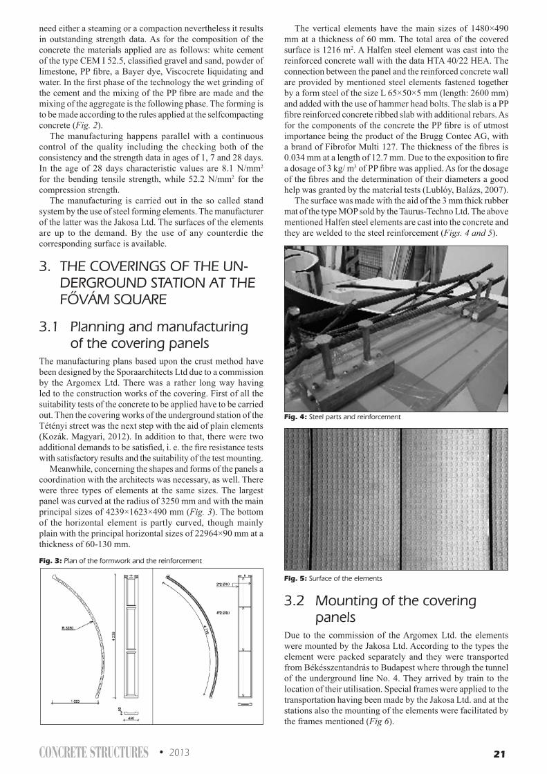
CONCRETE STRUCTURES • 2013 21
need either a steaming or a compaction nevertheless it results in outstanding strength data. As for the composition of the concrete the materials applied are as follows: white cement of the type CEM I 52.5, classified gravel and sand, powder of limestone, PP fibre, a Bayer dye, Viscocrete liquidating and water. In the first phase of the technology the wet grinding of the cement and the mixing of the PP fibre are made and the mixing of the aggregate is the following phase. The forming is to be made according to the rules applied at the selfcompacting concrete (Fig. 2).
The manufacturing happens parallel with a continuous control of the quality including the checking both of the consistency and the strength data in ages of 1, 7 and 28 days. In the age of 28 days characteristic values are 8.1 N/mm2 for the bending tensile strength, while 52.2 N/mm2 for the compression strength.
The manufacturing is carried out in the so called stand system by the use of steel forming elements. The manufacturer of the latter was the Jakosa Ltd. The surfaces of the elements are up to the demand. By the use of any counterdie the corresponding surface is available.
3. THE COVERINGS OF THE UN-DERGROUND STATION AT THE FôVÁM SQUARE
3.1 Planning and manufacturing of the covering panels
The manufacturing plans based upon the crust method have been designed by the Sporaarchitects Ltd due to a commission by the Argomex Ltd. There was a rather long way having led to the construction works of the covering. First of all the suitability tests of the concrete to be applied have to be carried out. Then the covering works of the underground station of the Tétényi street was the next step with the aid of plain elements (Kozák. Magyari, 2012). In addition to that, there were two additional demands to be satisfied, i. e. the fire resistance tests with satisfactory results and the suitability of the test mounting.
Meanwhile, concerning the shapes and forms of the panels a coordination with the architects was necessary, as well. There were three types of elements at the same sizes. The largest panel was curved at the radius of 3250 mm and with the main principal sizes of 4239×1623×490 mm (Fig. 3). The bottom of the horizontal element is partly curved, though mainly plain with the principal horizontal sizes of 22964×90 mm at a thickness of 60-130 mm.
The vertical elements have the main sizes of 1480×490 mm at a thickness of 60 mm. The total area of the covered surface is 1216 m2. A Halfen steel element was cast into the reinforced concrete wall with the data HTA 40/22 HEA. The connection between the panel and the reinforced concrete wall are provided by mentioned steel elements fastened together by a form steel of the size L 65×50×5 mm (length: 2600 mm) and added with the use of hammer head bolts. The slab is a PP fibre reinforced concrete ribbed slab with additional rebars. As for the components of the concrete the PP fibre is of utmost importance being the product of the Brugg Contec AG, with a brand of Fibrofor Multi 127. The thickness of the fibres is 0.034 mm at a length of 12.7 mm. Due to the exposition to fire a dosage of 3 kg/ m3 of PP fibre was applied. As for the dosage of the fibres and the determination of their diameters a good help was granted by the material tests (Lublóy, Balázs, 2007).
The surface was made with the aid of the 3 mm thick rubber mat of the type MOP sold by the Taurus-Techno Ltd. The above mentioned Halfen steel elements are cast into the concrete and they are welded to the steel reinforcement (Figs. 4 and 5).
3.2 Mounting of the covering panels
Due to the commission of the Argomex Ltd. the elements were mounted by the Jakosa Ltd. According to the types the element were packed separately and they were transported from Békésszentandrás to Budapest where through the tunnel of the underground line No. 4. They arrived by train to the location of their utilisation. Special frames were applied to the transportation having been made by the Jakosa Ltd. and at the stations also the mounting of the elements were facilitated by the frames mentioned (Fig 6).
Fig. 3: Plan of the formwork and the reinforcement
Fig. 4: Steel parts and reinforcement
Fig. 5: Surface of the elements

22 2013 • CONCRETE STRUCTURES
4. THE COVERING OF THE UN-DERGROUND STATION AT THE SZENT GELLÉRT SQUARE
The construction plans have been prepared by the Sporaarchitects Ltd. There are two differences in comparison with the plans of the above discussed underground station at the Fővám square. One of them is that the curved surface is smooth, while the other one is the different radius (Fig. 7).
5. FIRE PROTECTION TESTS
5.1 Determination of the testsThe tests concerning the fire protection have been carried out at the plant of the ÉMI Nonprofit Ltd. in Szentendre. The engineering expert was Ádám Varga. The destination of the tests was to clarify whether the partition of the railway area of the station and of the ventilation area behind satisfies the
requested tightness against smoke. For this purpose have been manufactured altogether twelve test pieces. Four horizontal, four vertical and four curved ones. The temperature of the chamber was checked by heat sensors, while the deformations were measured separately. The construction of the chamber was of the type Kipszer and it operated with oil. The inside temperature was 950°C.
5.2 The tests of the horizontal pieces
The temperature data have been measured with the aid of Ni-CrNi thermal elements, while the deflections were registered by a transmitter of Kübler type. Between the test pieces there was a gap of 10 mm width filled with a fire blocking material called Polylack Elastic and supplied by the Dunamenti Tűzvédelmi Zrt. The fastening of the test pieces was according to the construction plans, i, e. steel fasteners joined to the cast in Halfen elements coated with a fire protecting paint (Fig. 8).
5.3 The tests of the curved piecesIn the test 19 thermo elements have been placed on the side protected against fire in order to check the temperature of the surface and the warming up of the clearances. The mentioned clearances were of 10 mm width, they have been filled additionally with a material called Polylack Elastic. The fastenings have been made from profile steel and they were connected to the Halfen rails and coated with a fire protecting paint (Figs. 9 and 10).
Fig. 6: Storing elements
Fig. 7: Mounting of the curved panels
Fig. 8: Fire resistance of plain panels
Fig. 9: Fire resistance of curved panels

CONCRETE STRUCTURES • 2013 23
5.4 The fire resistance of the fastenings.
The fastenings are important parts of the coverings. The L 50×40×5 mm profiles and the applied bolts have been sized according to structural calculations and finally coated with a fire protecting paint. The cast in Halfen rails were also very important parts of the connections.
5.5 The smoke resistance of the filling material
The 10 mm wide clearances, between the panels have been filled with a fire blocking material called Polylack Elastic supplied by the Dunamenti Tűzvédelem Zrt. The demand was 30 minutes resistance time. In the tests an escape of the smoke was experienced only after 33 and 51 minutes (Fig 11.).
5.5 Tests resultsAfter a continuous checking both of the measured data and the pieces tested both the fire resistance and the resistance against the escape of the smoke proved to be satisfactory and they met the requirements.
The tests were not carried out as far as the utmost limit of the fire resistance. However, after cooling down a close inspection of the tested pieces resulted in the statement that no significant damages emerged (Table 1).
6. CONCLUSIONSThe PP reinforced concrete panels held out well both technologically and economically at the two mentioned underground stations of the line No. 4. and their application resulted in several advantages. Especially the fire resistance and the resistance against the escape of smoke are of utmost importance.
7. REFERENCESÉMI Nonprofit Ltd (2012): „Conclusions of the Testing Institute”, Test report
T-265/2011. Budapest, 2012. 2.10. (in Hungarian) Kozák, J., Magyari, B. (2012): „FRC Cladding at two Stations of the Underground
Line 4 in Budapest, Hungary”, CONCRETE STRUCTURES Journal 2012, pp. 51-53.
Kozák, J., Magyari, B., Tassi, G. (2011): „PPFRC Cornice and Wall Covering” CCC Proceedings 2011 Balatonfüred (Eds. Balázs, G.L. and Lublóy, É.), pp. 393-396.
Lublóy, É., Balázs, L, G., (2007): „Concrete Properties in Fire Depending on Type of Cement, Aggregate and Fibre” CCC Proceedings 2007 Visegrád (Ed. Balázs, G.L. and Nehm, S.G.), pp. 327-332.
Magyari, B. (2005): Fibre „Reinforced Concrete Elements Applied on Facades”, Proceedings of fib Symposium Budapest 2005 (Eds. Balázs, G.L. and Borosnyói, A.). pp. 86-91.
Magyari, B., Tassi, G. (2007): „Effect of Non-metallic Fibres on the Concrete Properties”, Proceedings of fib Symposium Dubrovnik 2007. pp. 367-374.
Pál, G. (2010): „The design of the underground station at the railway station Kelenföldi” (in Hungarian), VASBETONÉPÍTÉS 2010/1, pp. 8–13.
Schulek, J. (2008): „Budapest metro line 4 under construction”, CONCRETE STRUCTURES Journal 2008, pp. 10-14.
János Kozák (1953) graduated 1977 as a civil engineer on the Budapest University of Technology and Economics, being now a leading designer both for load-carrying structures and architecture. Since 1991 he is a manager at the Argomex Ltd. Beside architectural commissions and the manufacturing of cladding plates of façades the Argomex Ltd. produces cladding panels from a self compacting fine quality concrete core of high strength and of fibre reinforcement.
Béla Magyari dr (1942) graduated 1969 as a civil engineer on the Budapest University of Technology and Economics. 1978 he was awarded a dr. technical degree and 1982 that of the Doctor of Philosophy. From 1960 until 1969 he was active as a technical assistant of the ÉTI in Budapest. From 1969 until 1976 he was a department leader at the Co. Bácsépszer and from 1976 till 1990 he served the Co. Dutép as a chief quality engineer. Currently, though he is retired but active as a consulting engineer at the Argomex Ltd. His professional interest and activity include the concrete, reinforced concrete, the splice of reinforcing steel bars and concretes with fibre reinforcement.
Table 1: Summary of the test result
Fig. 10: Preparation of the test of the curved panels Fig. 11: End of the test
Propertiestested
Horizontal elemets (min.)
Curvedpanels (min.)
Fire resistance 68 70
Resistans againtsescape of smoke
51
33

24 2013 • CONCRETE STRUCTURES
VARIABILITY OF CONCRETE SURFACE HARDNESS MEASUREMENT PARAMETERS
Katalin Szilágyi – Adorján Borosnyói – István Zsigovics
The surface hardness tests of concrete may provide alternatives to drilled core tests for estimating the com-pressive strength of concrete in a structure. To arrive at an acceptable estimate of the compressive strength of a concrete structure by using surface hardness tests methods, one must account first of all for the uncer-tainty of the surface hardness test results; that is associated with the inherent variability (repeatability) of the test method. Present paper demonstrates the existence of an observational error of the rebound hammer test that is attributed to the design of the scale of the original rebound hammer. From the analysis of tens of thousands test data it can be concluded, that the observational error and the inherent variance of con-crete hardness are independent parameters. The within-test standard deviation and within-test coefficient of variation of rebound index over the average were found to have the same tendency as that of concrete strength has. Both variability parameters have a skewed distribution over the analysed rebound index range. As a closing focus of this paper the governing parameters for the changes of the coefficient of varia-tion are identified experimentally.
Keywords: concrete, rebound surface hardness, compressive strength, variability, repeatability.
1. INTRODUCTIONDuring the design of reinforced concrete structures the designer specifies the strength class of concrete that is taken into account in the calculations. The same is carried out if the performance of the concrete is determined by in-situ testing, e.g. surface hardness testing for strength estimation.
Reliability analysis techniques mostly concentrate on the use of the coefficient of variation to describe the variability of different material characteristics, rather than the standard deviation. Whether the standard deviation or the coefficient of
variation is the appropriate measure of dispersion for concrete strength depends on which of the two measures is more nearly constant over the range of strength (ACI, 2002).
Technical literature indicates that the standard deviation remains reasonably constant over a wide range of strength (Teychenné, 1973), however, the coefficient of variation is considered to be more applicable for within-test evaluations (ACI, 2002).
Fig. 1 illustrates the standard deviation and the coefficient of variation of concretes of average compressive strength in the range of 20 to 70 MPa, based on literature data (fib, 1999).
Fig. 1.a: Standard deviation of concrete compressive strength (fib, 1999). Fig. 1.b: Coefficient of variation of concrete compressive strength (fib, 1999).

CONCRETE STRUCTURES • 2013 25
A sufficient number of tests are needed to find the variation of concrete strength accurately and to be able to use statistical procedures for interpreting the test results. If only a small number of test results are available, the estimates of the standard deviation and coefficient of variation become less reliable (Carino, 1993).
2. SIGNIFICANCE OF THE STUDYThe surface hardness tests of concrete may provide alternatives to drilled core tests for estimating the compressive strength of concrete in a structure or they can provide additional data to core tests if limited number of cores can be obtained from a structure. In several cases the designer needs strength values that can be reliably used to specify the strength class of concrete rather than non-destructive measures alone, e.g. surface hardness test results. Therefore, to arrive at an acceptable estimate of the compressive strength of a concrete structure by using surface hardness tests methods, one must account for three primary sources of uncertainty (ACI, 2003): 1) the uncertainty of the surface hardness test results; 2) the uncertainty of the relationship between concrete strength and the measure of surface hardness; 3) the variability of the concrete strength in the structure.
The first source of uncertainty is associated with the inherent variability (repeatability) of the test method. Present paper provides information to this topic. Present paper refers to repeatability in accordance with ACI, 2003.
3. LITERATURE IMPLICATIONSThe ASTM C 805 standard provides precision statements for the rebound index of the Schmidt rebound hammers (ASTM, 2008). It is stated for the precision that the within-test standard deviation of the rebound index is 2.5 units, as “single-specimen, single-operator, machine, day standard deviation”. Therefore, the range of ten readings should not exceed 12 units (taking into account the p=0.95 probability level critical value for the studentized range statistic according to Harter, 1960). Dependence of the within-test standard deviation on the average rebound index is not indicated. Literature data support the ASTM C 805 suggestions (e.g. Mommens, 1977).
Ten years ago, the ACI 228.1R-03 Committee Report reapproved earlier implications on the statistical characteristics of the rebound surface hardness method as an extension of ACI 228.1R-89 (ACI, 1989; 2003). The Report illustrated – on the basis of three literature references from the 1980’s – that the within-test standard deviation of the rebound index shows an increasing tendency with increasing average and the within-test coefficient of variation has an apparently constant value of about 10%. No update has happened since then up today, however, particular literature data contradicted the above findings (e.g. Leshchinsky et al, 1990). Present paper provides a considerably more detailed collection of rebound index data, based both on own measurements and on a literature survey that can be a basis of a more reliable statistical analysis.
4. OBSERVATIONAL ERROR FOR THE REBOUND METHOD
The accuracy of statistical information is the degree to which extent the phenomena that was intended to be measured is described correctly (OECD, 2008). It is usually characterized in terms of error in statistical estimates and is traditionally composed by bias (systematic error) and variance (random error) components.
Systematic errors can lead to significant difference of the observed mean value from the true value of the measured attribute. Systematic errors can be either constant, or be related (proportional) to the measured quantity. Systematic errors are very difficult to deal with, because their effects are only observable if they can be removed. Such errors cannot be removed by repeating measurements or averaging large numbers of results. A simple method, however, to avoid systematic errors is the correct calibration: the use of the calibration anvil for the rebound hammers.
Random errors lead to inconsistent data. They have null expected value (scattered about the true value) and tend to have null arithmetic mean when a measurement is repeated. Random errors can be attributed either to the testing device or to the operator.
The observational error in the case of the rebound hammer is due to the design of the scale of the device. In Fig. 2 the reader can study the scale of the device. It can be seen that no odd values are indicated on the scale. Therefore the observer should decide on reading how the rounding of the read value is to be performed. As the repetition of the readings is very fast in a practical situation, it is expected that the observer adds an inherent observational error to the readings of the rebound index, in favour of the even numbers. The phenomena was indicated in particular publications for natural stones (Kolaiti, 1993) and concrete (Talabér et al, 1979) but was not analysed.
To see the magnitude and the influence of such an error on the reading of the rebound index, a comprehensive data survey was carried out by the authors of present paper. A total number of 45650 rebound index readings were collected from 28 different published sources. The data are based on both laboratory research and in-situ measurements. The rebound hammers were N-type original Schmidt hammers in each case.
Table 1 summarizes the statistical characteristics of the rebound index data in terms of counting the even or odd number readings. It is demonstrated that the observational error can be significant. On the total population of the 45650 data points one can find 57.3% frequency of even number readings and 42.7% frequency of odd number readings.
It should be noted here, however, that the 45650 data points are the result of several different operators, therefore, no general statement can be taken about operator precision or measurement uncertainty. The unbiasedness of the data collection is highly dependent on the operator. It is also noted that present paper does not have the aim to analyse in details if there is any bias attributed to the presented inherent observational error.
Fig. 3 gives a general indication of the operator obser-vational error considering the rebound index in present statistical analysis. Fig. 3 represents the empirical frequency histogram of the 45650 data.
The reader can clearly see how remarkable is the difference between the frequencies of adjacent even and odd number rebound index readings. As one extreme location, the vicinity of the rebound index of 40 can be highlighted: the difference between the relative frequencies of reading 40 and reading 41 exceeds 60%.
From the practical point of view of material testing – and not from that of the requirements of analytical accuracy of probability theory – one may ask that how much is the
Fig. 2: Scale of the rebound hammer.

26 2013 • CONCRETE STRUCTURES
influence of such an observational error on the reliability of concrete strength estimation based on the rebound hammer test, as it is the most important aim in most of the cases when the rebound hammers are used. Strength estimation usually means the estimation of the mean compressive strength based on the mean rebound index (mean can indicate here either the average or the median value of the rebound index) and random errors are usually expected to have an influence on kurtosis rather than the mean value.
The most erroneous dataset listed in Table 1 at the 28th line is selected for the demonstration of the significance of the phenomenon. The dataset can be found in the technical literature (for the right of privacy of the original author no reference is given here as this example is a bad one). The 1140 rebound index readings are the result of a test series conducted
on 5 different concrete mixes where 20 replicate readings were recorded at 57 individual measuring locations.
The statistical parameters of the strength measurements for the 5 mixes can be studied in Table 2. Variability parameters indicate a very low level of quality control during the tests (compare to Fig. 1). The overall statistical parameters of the rebound hardness measurements for the 5 mixes are introduced in Table 3. The resulted range of 31 shall not be criticised in the view of ASTM C 805, as these readings are not of the same specimens. On the first look, the differences between the statistical parameters related to even and odd readings can be considered to be negligible. If one takes a look at a more detailed statistical parameter check then more reliable conclusions may be drawn.
The rebound index ranges of individual measuring locations are shown in Fig. 4.a, indicating with black tone the locations where the limit of 12 units suggested by ASTM C 805 is violated.
The observational error is given in Fig. 4.b, which diagram shows the differences (in percents) between the only-even-number and only-odd-number averages calculated to each location. The deviation has a positive sign if the only-even-number average is higher and has a negative sign if the only-odd-number average is higher. It can be seen that the error can reach the magnitude of 20% at specific locations.
The diagram indicates with a striped tone those locations where zero odd reading was recorded and therefore the error is practically 100%. It can be realized by the comparison of the two diagrams that the observational error (Fig. 4.b) and the inherent variance of concrete hardness (i.e. the range, Fig. 4.a) are independent parameters, therefore, they can be separated and determined individually in theoretical analyses.
It can be summarized as a conclusion that the observational error can be considerable in particular cases, therefore, future statistical analyses are needed to make clear the real influences. It is suggested, however, that a simple development of the testing device can eliminate majority of the observational error: a scale of the index rider would be needed that indicates both even and odd values rather than only even values as it is the case for the original design.
5. REPEATABILITY OF THE REBOUND TEST METHOD
For the present repeatability analysis a total number of 3511 data-pairs of corresponding average rebound indices and standard deviations of rebound indices was collected from
Table 1: Statistical characteristics of the rebound index data in terms of counting the even or odd number readings
Total readings,
N
Readings of even
numbers,Neven
Readings of odd
numbers,Nodd
Relative error,
(Neven–Nodd)/N, %
Source of data
1 2160 1088 1072 +0.74% lab2 270 133 137 –1.48% lab3 120 62 58 +3.33% in-situ4 120 63 57 +5.0% in-situ5 1179 621 558 +5.34% lab6 1120 603 517 +7.68% in-situ7 7640 4189 3451 +9.66% lab8 510 284 226 +11.37% in-situ9 140 62 78 –11.43% in-situ10 1000 561 439 +12.20% in-situ11 2880 1623 1257 +12.71% lab12 5310 2999 2311 +12.96% in-situ13 200 113 87 +13.00% in-situ14 200 113 87 +13.00% in-situ15 3760 2151 1609 +14.41% lab16 990 570 420 +15.15% in-situ17 7560 4380 3180 +15.87% lab18 800 464 336 +16.00% lab19 70 41 29 +17.14% in-situ20 451 183 268 –18.85% in-situ21 460 276 184 +20.00% in-situ22 1070 644 426 +20.37% lab23 210 129 81 +22.86% in-situ24 1440 905 535 +25.69% lab25 2980 1873 1107 +25.70% lab26 1670 1102 568 +31.98% lab27 250 84 166 –32.80% in-situ28 1140 880 260 +54.39% lab
Fig. 3: Observational error of the rebound index.Table 2: Statistical parameters of the strength measurements of the most erroneous dataset
fcm, MPa s, MPa V, %Mix 1) 45.8 7.48 16.3Mix 2) 48.3 8.81 18.3Mix 3) 46.9 1.03 2.2Mix 4) 34.3 1.73 5.1Mix 5) 29.4 2.38 8.1
Table 3: Statistical parameters of the rebound hardness measurements of the most erroneous dataset
Overall range Rmax - Rmin = 51-20 = 31
Overall average rebound index Rm = 48.3
Overall standard deviation sRm = 3.95
Average of the 880 even readings Rm,even = 32.38
Average of the 260 odd readings Rm,odd = 32.18
Standard deviation of the 880 even readings sRm,even = 3.80
Standard deviation of the 260 odd readings sRm,odd = 4.42

CONCRETE STRUCTURES • 2013 27
31 different sources (total number of readings: 47340). The data are based on both laboratory research and in-situ measurements. The rebound hammers used were N-type original Schmidt hammers in each case. The data is provided either by technical literature or from the data archives of the accredited testing laboratory of the BME Department of Construction Materials and Engineering Geology. The averages and the standard deviations were calculated by 9 to 20 replicate rebound index readings on the same surface of a concrete specimen during laboratory tests, or at the same measuring area in the case of in-situ testing. These data were analysed to see the general repeatability (within-test variation) behaviour of the rebound hammer testing. The range of the analysed data was from Rm,min = 12.2 to Rm,max = 58.6 for the averages and from sR,min = 0.23 to sR,max = 7.80 for the standard deviations. Coefficient of variation was also calculated and analysed. Range was found to be as from VR,min = 0.43% to VR,max = 31.2%. Analysis of reproducibility (batch-to-batch variation) was not the aim of the authors.
Fig. 5.a shows the graphical representation of the statistical analysis considering the within-test variation as the standard deviation over the average, while Fig. 6.a indicates the same but considering the within-test variation as the coefficient of variation over the average. The reader can clearly realize that these parameters have the same tendency as the within-test variation of concrete strength has, as it was demonstrated earlier by Fig. 1; i.e. no tendency is found in the standard deviation over the average and a clear decreasing tendency can be observed in the coefficient of variation by the increasing average. Hence the implications given by the ACI 228.1R-03 Committee Report are suggested to be reconsidered.
6. DISTRIBUTION OF REPEATABILITY PARAMETERS FOR THE REBOUND TEST METHOD
The relatively large number of data made it possible to study the distribution of the repeatability parameters. The empirical
frequency histograms are constructed for the standard deviation (Fig. 5.b) and for the coefficient of variation of the rebound index readings (Fig. 6.b). Both parameters have a skewed distribution over the analysed rebound index range, therefore, a lognormal probability distribution is suggested to be taken into account in theoretical analyses. The findings confirm experimental data available for the distribution of the repeatability parameters of concrete strength (Soroka, 1971). Shimizu et al (2000) demonstrated – based on an extensive analysis of 10788 drilled core samples taken from 1130 existing reinforced concrete buildings with compressive strength fcm = 10-50 MPa – that the coefficient of variation of concrete strength had a lognormal probability distribution while normal probability distribution was found for the strength. Considering the distributions of the standard deviation and the coefficient of variation of concrete strength indicated in Fig. 1 the same observation can be made as was found by Shimizu et al (2000).
As the skewness is remarkable for both Fig. 5.b and Fig. 6.b, it is suggested to refer to the modus (= mode) values rather than the average.
It can be concluded that the modus value for the standard deviation of the rebound index is 1.3–1.8 and the modus value for the coefficient of variation of the rebound index is 3.0%–4.0%, based on a total number of 3511 data-pairs of corresponding average rebound indices and standard deviations of rebound indices collected from 31 different published sources (total number of readings: 47340).
7. INFLUENCES ON THE REPEATABILITY OF THE REBOUND TEST METHOD
From a reliability analysis point of view one may practically select the coefficient of variation as the parameter of repeatability for the rebound hammer test. For this purpose, however, the governing parameters over the changes of the coefficient of variation are needed to be known.
The authors of present paper have analysed the available database in this sense as well, with the selection of the
Fig. 4.a: Range of rebound index, 4.b Specific observational error of rebound index (corresponding to results of Table 1, 28th line)

28 2013 • CONCRETE STRUCTURES
following possible influencing parameters: the w/c-ratios of the concretes, the age of the concretes, the cement types used for the concretes, the testing conditions of the concretes (dry/wet), the carbonation depths of the concretes and the impact energy of the rebound hammers (N-type original Schmidt hammer with impact energy of 2.207 Nm or L-type original Schmidt hammer with impact energy of 0.735 Nm).
For the analysis of the influence of the age of the concretes, 102 different concrete mixes were selected mostly from own laboratory measurements, for which the development of the coefficient of variation was possible to be followed in time. The age of the tested concretes was between 1 day and 240 days. The measuring device was N-type original Schmidt hammer. The behaviour was found to be typically independent from the concrete compositions, it was reasonable, therefore, to prepare a smeared, unified response for all the 102 concrete mixes (Fig. 7).
The following observations can be made. In the first 14 days a rapid decrease in the coefficient of variation is measured that is attributed to the fast hydration process and the gradual drying of the tested surfaces. A minimum is reached in the coefficient of variation at the age of 28 to 56 days. The reason is the decrease of the rate of hydration. Over 56 days of age a gradual increase is observed in the coefficient of variation attributed to the more and more pronounced influence of carbonation.
The direct relationship between the depth of carbonation and the within-test coefficient of variation of the rebound index is discussed later in this chapter.
The 102 concrete mixes selected for the above analysis made possible to analyse the influence of the cement type on the repeatability parameters, as well. Nine cement types were studied (in accordance with the designations used in EN 197-1 European Standard and MSZ 4737-1 Hungarian Standard): CEM I 32.5; CEM I 42.5 N; CEM I 42.5 N-S; CEM I 52.5; CEM II/A-S 42.5; CEM II/A-V 42.5 N; CEM II/B-M (V-L) 32.5 N; CEM III/A 32.5 N-MS; CEM III/B 32.5 N-S. The influence of the applied cements was visible and robust (Fig. 8).
It was found experimentally that the lowest coefficient of variation can be reached for the rebound index with the use of CEM I type Portland cements over the studied period of time.
The coefficient of variation is increasing with decreasing the strength class of CEM I type Portland cements (not illustrated in Fig. 8). The use of blended cements (CEM II) or slag cements (CEM III) always resulted in higher coefficient of variation over the studied period of time, when compared to reference mixes made with Portland cements (CEM I).
Differentiation between the influences of different hydraulic additives (fly ash to slag) for the blended cements (CEM II) or
Fig. 5.a: Standard deviation of rebound index over the average.Fig. 5.b: Empirical probability distribution histogram of the standard deviation of the rebound index.
Fig. 6.a: Coefficient of variation of rebound index over the average.Fig. 6.b: Empirical probability distribution histogram of the coefficient of variation of the rebound index.

CONCRETE STRUCTURES • 2013 29
between the amount of slag applied for the slag cements (CEM III) was not possible due to the limited data available. Future research is needed in this field.
The influence of the water-cement ratio was possible to be studied for six types of cements analysing the results of 93 different concrete mixes. The range of the studied water-cement ratios was w/c = 0.35 to w/c = 0.65. It was realized, that the coefficient of variation of the rebound index becomes lower if the water-cement ratio is decreased while all other concrete technology parameters (including compacting) are kept constant.
As mentioned above, the carbonation was found to have a more pronounced influence on the repeatability of the rebound hammer tests on mature concretes, therefore, a targeted analysis was performed on mature concrete specimens the age of which was 2 to 5 years during testing. 30 different mixes of concretes were selected for the analysis with the range of compressive strength of 42.6 to 91.7 MPa. The measured depths of carbonation were found to be between 2.2 mm to 22.8 mm. It was demonstrated that the coefficient of variation of the rebound index is higher for higher depths of carbonation (Fig. 9).
The authors of present paper have found during their earlier in-situ testing experiences on fired clay masonry structures that the within-test standard deviation and the within-test coefficient of variation of the rebound index is very sensitive to the impact energy, therefore, a comparative study was performed on concretes using L-type and N-type original Schmidt hammers to reveal the existence of this influence for concretes as well. CEM 42.5 N type cement was selected and w/c = 0.40 – 0.50 – 0.65 water-cement ratios were applied for the same aggregate mix. In the concretes both the cement paste content and the consistency was set to be constant. The age of the test specimens was 3 to 240 days. It was demonstrated also for concretes that both the standard deviation and the coefficient of variation of the rebound index is very sensitive to the applied impact energy before the age of 90 days. The scatter of results is greater corresponding to the lower impact energy. Experiments showed that the differences become more balanced and seem to disappear at ages over 90 days.
8. CONCLUSIONSThe estimation of the compressive strength of concrete by surface hardness tests methods needs the knowledge of the uncertainties of the test results that are associated with the inherent variability (repeatability) of the test method. Present
paper extends the precision statements of ASTM C 805 for the rebound index in terms of observational error of rebound index readings. It is demonstrated that an operator observational error exists for the rebound hammer tests that is originated from the design of the scale of this device. It is demonstrated that the observational error is highly dependent on the operator of the rebound hammer and can be considerable at particular cases.
It is demonstrated that the observational error and the inherent variance of concrete hardness are independent parameters.
It is demonstrated for the repeatability (within-test variation) behaviour of the rebound hammer tests that there is no tendency in the standard deviation of the rebound index over the average and a clear decreasing tendency can be observed in the coefficient of variation of the rebound index over the average by the increasing average. Therefore, the implications given by the ACI 228.1R-03 Committee Report are suggested to be reconsidered.
A remarkable skewness is demonstrated for the distribution of both repeatability parameters (standard deviation and coefficient of variation of rebound index). The modus (= mode) value for the standard deviation of the rebound index is 1.3–1.8 and the modus value for the coefficient of variation of the rebound index is 3.0%–4.0%.
Fig. 7: Coefficient of variation of rebound index in time.Fig. 9: Coefficient of variation of rebound index vs. average depth of carbonation.
Fig. 8: Influence of the type of cement on the coefficient of variation of rebound index in time.

30 2013 • CONCRETE STRUCTURES
Strong influences of the w/c and the age of the concretes; the type of cement; the testing conditions; the carbonation depths of the concretes; and the impact energy of the rebound hammers were demonstrated considering the coefficient of variation of the rebound index.
Results indicate several further directions of future research in the field.
9. ACKNOWLEDGEMENTSThe work reported in the paper has been developed in the framework of the project “Talent care and cultivation in the scientific workshops of BME” supported by the grant TÁMOP-4.2.2.B-10/1-2010-0009. The authors gratefully acknowledge the support of the Jedlik Ányos PhD Candidate Scholarship supported by the National Excellence Program TÁMOP 4.2.4. A/1-11-1-2012-0001 - Elaborating and Operating an Inland Student and Researcher Personal Support System national program. The authors appreciate very much the detailed discussions of the manuscript by Dr. Attila Erdélyi and by Dr. Herbert Träger, which contributed to improve the quality of the paper.
10. GLOSSARYAccuracy: closeness of computations or estimates to the
exact or true values that the statistics were intended to measure (OECD, 2008).
Batch-to-batch variation: reproducibility (ACI, 2003).Bias: an effect which deprives a statistical result of
representativeness by systematically distorting it, as distinct from a random error which may distort on any one occasion but balances out on the average (OECD, 2008).
Frequency: the number of occurrences of a given type of event or the number of observations falling into a specified class (ISO 3534-1).
Kurtosis: a term used to describe the extent to which a unimodal frequency curve is “peaked”; that is to say, the extent of the relative steepness of ascent in the neighbourhood of the mode. The term was introduced by Karl Pearson in 1906 (OECD, 2008).
Modus: the Latin name for mode; the value that appears most often in a set of data (OECD, 2008).
Observational error: operator error in the use of original Schmidt rebound hammer due to the inaccurate reading of the index rider scale.
Performance error: operator error in the use of original Schmidt rebound hammer due to the inaccurate inclination of the device (i.e. not precisely perpendicular to the tested surface) during impact.
Precision: the property of the set of measurements of being very reproducible or of an estimate of having small random error of estimation (OECD, 2008).
Random error: an error, that is to say, a deviation of an observed from a true value, which behaves like a variate in the sense that any particular value occurs as though chosen at random from a probability distribution of such errors (OECD, 2008).
Repeatability: precision under conditions where independent test results are obtained with the same method on identical test items in the same laboratory by the same operator using the same equipment within short intervals of time (ISO 3534-1).
Reproducibility: precision under conditions where test results are obtained with the same method on identical test
items in different laboratories with operators using different equipment (ISO 3534-1).
Skewness: a term for asymmetry, in relation to a frequency distribution; a measure of that asymmetry (OECD, 2008).
Studentized range: the difference between the largest and smallest data in a sample measured in units of sample standard deviations (Harter, 1960).
Within-test variation: repeatability (ACI, 2003).
11. REFERENCESASTM C 805/C 805M–08 Test Method for Rebound Number of Hardened
Concrete, 2008, 3 p.ACI (1989) “In-Place Methods to Estimate Concrete Strength”, ACI 228.1R-
89, American Concrete Institute, Farmington Hills, Michigan, 26 p.ACI (2002) “Evaluation of Strength Test Results of Concrete”, ACI 214R-02,
American Concrete Institute, Farmington Hills, Michigan, 20 p.ACI (2003) “In-Place Methods to Estimate Concrete Strength”, ACI 228.1R-
03, American Concrete Institute, Farmington Hills, Michigan, 44 p.Carino, N. J. (1993) “Statistical Methods to Evaluate In-Place Test Results”,
New Concrete Technology: Robert E. Philleo Symposium, ACI SP-141, T. C. Liu and G. C. Hoff, eds., American Concrete Institute, Farmington Hills, Michigan, pp. 39-64.
fib Bulletin 3 (1999) “Structural Concrete – Textbook on Behaviour, Design and Performance”, Vol. 3, fédération internationale du béton (fib), December 1999, pp. 247-248.
Harter, H. L. (1960) “Tables of Range and Studentized Range”, The Annals of Mathematical Statistics, Vol. 31, No. 1960, pp. 1122-1147, 1960
ISO 3534-1:2006 “Statistics – Vocabulary and symbols – Part 1: Probability and general statistical terms”
Kolaiti, E., Papadopoulos, Z. (1993) “Evaluation of Schmidt rebound hammer testing: A critical approach”, Bulletin of the International Association of Engineering Geology, Paris, No.48, 1993, pp. 69-76.
Leshchinsky, A. M., Leshchinsky, M. Yu., Goncharova, A. S. (1990) „Within-Test Variability of Some Non-Destructive Methods for Concrete Strength Determination”, Magazine of Concrete Research, V. 42, No. 153, pp. 245-248.
Mommens, A. (1977) “La precision de l’estimation de la résistance du béton au moyen de l’indice sclérométrique”, Matériaux et Constructions, Vol. 10, No. 55, 1977, pp. 49-54.
OECD (2008) “Glossary of Statistical Terms”, Organisation for Economic Co-operation and Development, 2008, 605 p., ISBN 978-92-64-025561
Shimizu, Y., Hirosawa, M., Zhou, J. (2000) “Statistical analysis of concrete strength in existing reinforced concrete buildings in Japan”, Proceedings 12WCEE 2000: 12th World Conference on Earthquake Engineering, January 30 – February 4, 2000, Auckland, New Zealand, No. 1499, pp. 1-8.
Soroka, I. (1971) “On compressive strength variation in concrete”, Matériaux et Constructions, Vol. 4, No. 21, 1971, pp. 155-161.
Talabér, J., Borján, J., Józsa, Zs. (1979) “Preliminaries to the standardization of non-destructive tests in concrete technology”, Bulletin of the BME Department of Building Materials, Budapest, No. 29, 1979, 112 p. (in Hungarian)
Teychenné, D. C. (1973) “Recommendations for the treatment of the variations of concrete strength in codes of practice”, Matériaux et Constructions, Vol. 6, No. 34, 1973, pp. 259-267.
Katalin Szilágyi (1981) civil engineer (MSc), PhD candidate at the Department of Construction Materials and Engineering Geology, Budapest University of Technology and Economics. Main fields of interest: diagnostics of concrete structures, non-destructive testing of concrete and silicate porous solids, concrete technology. Member of the Hungarian Group of fib. Member of RILEM Technical Committee ISC “Non destructive in situ strength assessment of concrete”.
Dr. Adorján Borosnyói (1974) civil engineer (MSc), PhD, associate professor at the Department of Construction Materials and Engineering Geology, Budapest University of Technology and Economics. Main fields of interest: application of non-metallic (FRP) reinforcements for concrete structures, bond in concrete, non-destructive testing of concrete. Member of the Hungarian Group of fib and of fib TG 4.1 „Serviceability Models”. Member of RILEM Technical Committee ISC “Non destructive in situ strength assessment of concrete”.
Dr. István Zsigovics (1949) civil engineer (MSc), PhD, senior lecturer at the Department of Construction Materials and Engineering Geology, Budapest University of Technology and Economics. Main fields of interest: concrete technology, self-compacting concretes, diagnostics of concrete structures, non-destructive testing of concrete. Member of the Hungarian Group of fib.

CONCRETE STRUCTURES • 2013 31
EFFECTS OF HIGH TEMPERATURE ON THE COMPRESSIVE STRENGTH OF POLYMER CONCRETE
Orsolya Németh – Éva Lublóy – György Farkas
Polymer concrete is defined as a type of concrete in which the binding material is only polymer. Establish-ment of connections between structures and the reconstruction of structures are major applications of poly-mer concretes. However, they are essentially influenced by the change of temperature and the load caused by fire. Our study introduces the changes caused by thermal load in the mechanical properties of a polymer concrete. During the tests, the polymer concrete specimen was subjected to load in four stages and after cooling down the residual compressive strength was determined. The results show that the strength reduc-tion was approximately 5% of the original compressive strength. Tests were performed also in heated con-dition (in-situ). In this case the compressive strength continuously decreased as the temperature increased. However, the conclusion of this research is that at high temperatures the polymer concrete had excessively reduced compressive strength; after cooling down the binding agent solidified again and it recovered 95% of its original compressive strength.
Keywords: polymer concrete, thermal load, high temperature, compression strength, residual compression strength
1. INTRODUCTION The word “concrete” usually means cement concrete, in which the binder is cement. If the binder is artificial resin (polymer), then we talk about artificial resin (polymer) concrete (herein-after the currently accepted term ’polymer concrete’ is to be used). The rapid solidification, excellent strength parameters, durability, high resistance against corrosive agents, high abra-sion resistance, low water permeability and resistance against freeze and thaw effects makes polymer concrete an extremely versatile material (Balaga-Beaudoin,1985, Fowler, 2003).
Although polymer concrete is a relatively young building material, it has a lot of applications already. It can be used for reinforcing and repairing of structures, for forming pave-ments and wear-resistant layers. Research works in the litera-ture (ACI Committe 548, 1996) primarily test the properties of concrete intended for given purposes. In order to enable the spread of a new material, its mechanical and physical properties should be tested systematically. The strength and physical characteristics of polymer concrete primarily depend on the types of binder and admixture. Our research only and exclusively studies concrete that binder is unsaturated poly-ester (UP polymer concrete). Earlier research and our tests performed indicate that the properties of polymer concrete of identical composition and produced under identical circum-stances are identical, and their quality is uniform.
This research aims to examine the properties of UP polymer concrete in detail. Compression strength, flexural strength, the modulus of elasticity (Németh, 2012), short-term and long-term shrinkage (Németh-Farkas, 2012) are discussed. The fire resistance, and the behaviour of UP poly-mer concrete exposed to high temperatures are the objectives
of this paper. The basis of specifications to determine load bearing, the compressive strength shall be tested in heated condition (in-situ) and after cooling down.
2. FIRE RESISTANCE OF POLYMER CONCRETE
The binders of polymer concrete are organic materials, their heat resistance is much lower than that of inorganic the mate-rials (e.g. stone, cement and metal). High temperature results degradation and, finally, loss of strength of the resin (Balaga-Beaudoin, 1985).
The features of some resins change drastically if tempera-ture reaches the softening temperature of resin (HDT – heat distortion temperature). At this temperature the resin starts to soften, deform or possibly flow as a result of the load. Where performance is expected even at increased temperatures as well, a detailed test in a temperature range including the ex-pectable exposure temperature is recommended.
Polymer concrete mixes do not tolerate the impact of fire if their resin content is 10% or more. Most polymer concretes with a resin content higher than 10% require a fire-retarding additive if the prevention of inflammability is an expectation (ACI Committe 548, 1996).
3. MATERIAL COMPOSITIONThe following tests were carried out to determine the proper-ties for the composition mixture (Tab. 1). The construction material made by the recipe will here be referred to as “UP polymer concrete”, meaning polymer concrete whose binder

32 2013 • CONCRETE STRUCTURES
is unsaturated polyester. Tab. 1 also includes the components of comparative (reference) cement concretes (Balázs-Lublóy, 2010).
4. EXPERIMENTAL METHODS AND RESULTS
4.1 Measurements with derivatography
Derivatographic measurement is a simultaneous thermo-ana-lytical method which simultaneously produces TG (thermo-gravimetric), DTA (differential thermo-analysis) and DTG (derivative thermo-gravimetric) signs. A small amount of the sample was smashed, put in a skillet of an inert material (corundum or platinum), and annealed in furnace at an even heat-up speed (in the so-called dynamic mode). Meanwhile the changes in the mass of the sample (TG curve) were mea-sured by an analytical balance and the changes of enthalpy taking place in the sample compared to the temperature of an inert material in the furnace chamber (DTA curve) were measured by thermo-elements. The appliance produces the first derivative of the TG curve, i.e. the DTG curve, in an analogous manner, which determines the place and extent of the processes accompanying the change of mass on the tem-perature scale. The above three curves and the test result also containing the temperature (T °C) sign and taken in function of the measurement time (t min) are called the derivatogram. The derivatogram can be shown in the function of tempera-ture (T ºC) as well. A derivatograph Q-1500 D appliance was used for the measurements (Fig. 1). The parameters of the derivatographic measurement were as follows:
- reference material: aluminium oxide,- heatig-up speed: 10ºC/minute, - temperature range: 20-1000ºC,- measured mass of sample: 200 mg,- TG sensitivity: 50 mg.
Results of the derivatographic measurements are summa-rized in Fig 2. It can be read from the DTA and DTG curves that the binder of the polymer concrete undergoes a softening process between 300°C and 400°C and the phenomenon is accompanied by a change of mass.
4.2 Fire resistance testIn the case of tests at high temperatures or tests following heat effects the rate and type of heat load are essential issues. Based on data described in literature and in the standards, several kinds of fire curves are used for the experiments. In this case a heating up curve approximating the normative fire curve was used, i.e. the one applicable to buildings and halls of architectural engineering. Tests were carried out without applying any direct flame effect.
Tab. 1: Material composition
Fig. 1: Derivatograph Q-1500 D
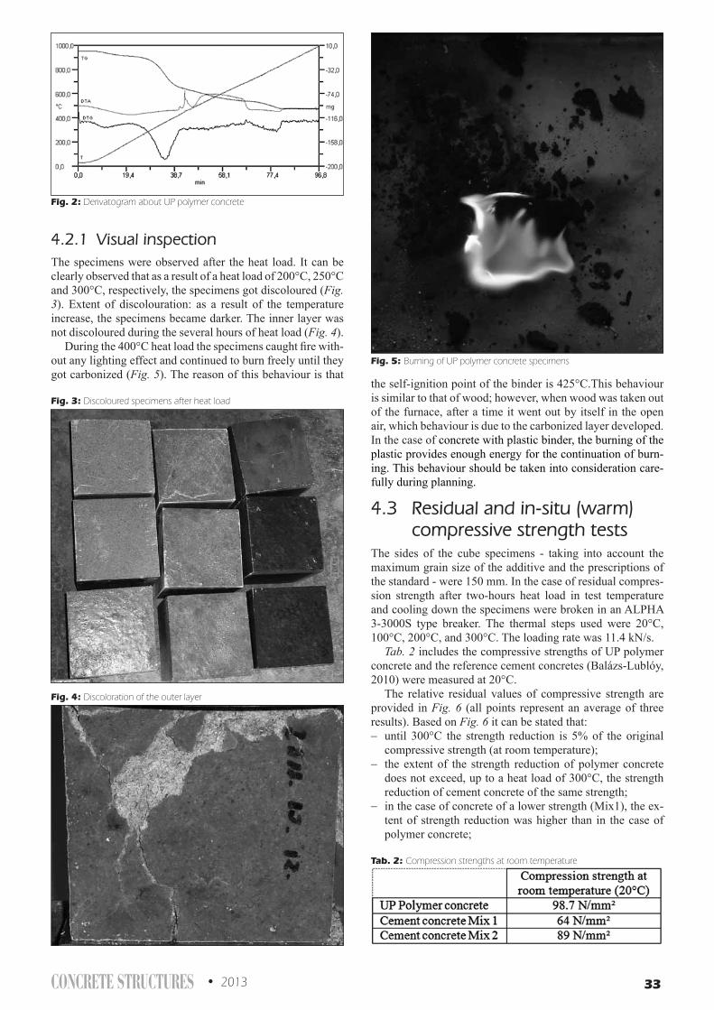
CONCRETE STRUCTURES • 2013 33
4.2.1 Visual inspectionThe specimens were observed after the heat load. It can be clearly observed that as a result of a heat load of 200°C, 250°C and 300°C, respectively, the specimens got discoloured (Fig. 3). Extent of discolouration: as a result of the temperature increase, the specimens became darker. The inner layer was not discoloured during the several hours of heat load (Fig. 4).
During the 400°C heat load the specimens caught fire with-out any lighting effect and continued to burn freely until they got carbonized (Fig. 5). The reason of this behaviour is that
the self-ignition point of the binder is 425°C.This behaviour is similar to that of wood; however, when wood was taken out of the furnace, after a time it went out by itself in the open air, which behaviour is due to the carbonized layer developed. In the case of concrete with plastic binder, the burning of the plastic provides enough energy for the continuation of burn-ing. This behaviour should be taken into consideration care-fully during planning.
4.3 Residual and in-situ (warm) compressive strength tests
The sides of the cube specimens - taking into account the maximum grain size of the additive and the prescriptions of the standard - were 150 mm. In the case of residual compres-sion strength after two-hours heat load in test temperature and cooling down the specimens were broken in an ALPHA 3-3000S type breaker. The thermal steps used were 20°C, 100°C, 200°C, and 300°C. The loading rate was 11.4 kN/s.
Tab. 2 includes the compressive strengths of UP polymer concrete and the reference cement concretes (Balázs-Lublóy, 2010) were measured at 20°C.
The relative residual values of compressive strength are provided in Fig. 6 (all points represent an average of three results). Based on Fig. 6 it can be stated that:− until 300°C the strength reduction is 5% of the original
compressive strength (at room temperature);− the extent of the strength reduction of polymer concrete
does not exceed, up to a heat load of 300°C, the strength reduction of cement concrete of the same strength;
− in the case of concrete of a lower strength (Mix1), the ex-tent of strength reduction was higher than in the case of polymer concrete;
Fig. 2: Derivatogram about UP polymer concrete
Fig. 3: Discoloured specimens after heat load
Fig. 4: Discoloration of the outer layer
Fig. 5: Burning of UP polymer concrete specimens
Tab. 2: Compression strengths at room temperature

34 2013 • CONCRETE STRUCTURES
− over 300°C the UP polymer concrete started to burn and continued to burn freely until the specimens got carbon-ized, practically until their strength was considered to be zero.In the case of in-situ (warm) compressive strength test
after the heat load the specimens were tested immediately, at testing temperature. The thermal steps used were 50°C, 100°C, 150°C, and 200°C. The test method and equipment was the same, as in the residual strength test.
The in-situ (warm) values of compressive strength are provided in Fig. 7 (all points represent an average of three results). Based on Fig. 7 it can be stated that:− the compressive strength decreases exponentially as the
temperature increases;− when the temperature reaches the melting point of the
binder (146°C), it begins to flow, then the strength of the composite becomes negligibly small.Based on the results above, the temperature-dependent
strength reductions factor Θ(t) can be determined (Fig. 8), to calculate the compressive strength of UP polymer concrete at a given temperature (Eq. 1):
fT = Θ(t) · fUP(20°C) (1)
where fT is the compressive strength at a given temperature, Θ(t) is the reductions factor and fUP(20°C) is the compres-sive strength at room-temperature.
The formula proposed for the temperature-dependent reduction factor (Eq. 2) is:
Θ(t) = 1.7935 · e-0.02t (2)
where Θ(t) is the strength reduction factor and t is the tem-perature.
5. CONCLUSIONS This study examined the effect of high temperatures on UP polymer concrete. Experiments were conducted to detect the behaviour of UP polymer concrete at these temperatures and after cooling down. The observations and measurements made during the experiments yield the following conclusions:− as the temperature increases, the compressive strength of
UP polymer concrete decreases exponentially;− the compression strength at a given temperature can be
calculated using the formula proposed for reduction factor Θ(t) according to (1) and (2);
Fig. 6: Relative residual values of compressive strength dependent of temperature
Fig. 7: In-situ (warm) and relative residual values of compressive strength dependent temperature
Fig. 8: The curve of temperature dependent reductions factor (Θ(t))

CONCRETE STRUCTURES • 2013 35
− around 150 °C the binder melts and the strength of the composite comes negligibly small;
− after cooling, the binder solidifies again, and the UP poly-mer concrete restores a major part of its compressive strength without any external intervention, that is, “regen-eration” takes place;
− loss of compressive strength after 300°C heat load is only 5% of the original strength.
6. ACKNOWLEDGEMENTS The work reported in the paper has been developed in the framework of the project „Talent care and cultivation in the scientific workshops of BME” project. This project is sup-ported by the grant TÁMOP-4.2.2.B-10/1--2010-0009.
7. REFERENCESACI Committe 548. (1996): „Polymer Concrete – Structural Applications
State-of-the Art Report”, American Concrete Institute, Farmington Hills, Michigan
Balaga, A., Beaudoin, J.J. (1985): „CBD-242. Polymer Concrete”, Division of Building Research, National Research Council Canada, Canadian Building Digest
Balázs, Gy. L., Lublóy, É. (2010): „Concrete at high temperature“, Proceed-ings of the Third International fib Congress incorporating the PCI An-nual Convention and Bridge Conference, Washington D.C.
Fowler, D. W. (2003): „Polymers in concrete: Where have we been and where are we going?“, Polymers in concrete: The first thirty years, Amer-ican Concrete Institute, Farmington Hills, Michigen, pp.111-117.
Németh, O. I. (2012): „Effects of thermal load to the mechanical proper-ties of polymer concrete”, Proceedings of the 9th fib International PhD Symposium in Civil Engineering, Karlsruhe, pp. 473-478.
Németh , O. I., Farkas, Gy. (2012): „Shrinkage of polymer concrete”, Pro-ceedings of the 8th Central European Congress on Concrete Engineer-ing, Plitvice Lakes, pp. 183-188.
Orsolya Németh (1984) civil engineer, PhD student at the Department of Structural Engineering at the Budapest University of Technology and Eco-nomics. Research field: mechanical and chemical properties of polymer con-crete. Member of the Hungarian Group of fib.
Éva Lublóy (1976), PhD, Senior lecturer in structural engineering, at the Budapest University of Technology and Economics. Her main fields of interesting are: fire design, behaviour of constructions materials at elevated temperature. Member of the Hungarian Group of fib.
Prof. György Farkas (1947) civil engineer, post-graduated in engineering mathematics, PhD, professor, co-head of the Department of Structural Engi-neering at the Budapest University of Technology and Economics. Research field: modelling and strengthening of reinforced and prestressed concrete structures, post-tensioned floor slabs, structural dynamics, HSC/HPC struc-tures. Member of the Hungarian Group of fib.

36 2013 • CONCRETE STRUCTURES
FIRE DESIGN OF CONCRETE-STEEL COMPOSITE STRUCTURES
Viktória Vass - Éva Lublóy - László Horváth - György L. Balázs
In the past decades numerous fire cases have indicated the importance of fire design. The design pos-sibilities of composite structures at elevated temperatures are discussed in the present paper. Designing composite structures at normal temperature is also a complex task, but the different behaviour of steel and concrete at elevated temperatures makes the fire design more complicated. The Eurocode 4 gives simplified methods to determine the fire resistance of the most commonly used composite cross-sections, and provides principles to analyse the behaviour of composite structures in fire.
Keywords: composite structures, concrete, steel, elevated temperature, design
1. INTRODUCTIONThe main purpose of fire design is the protection of human life. Basically it can be divided into two parts: prevention and fire fighting–rescue. During the fire design of buildings, according to the endangerment of human life and human goods, a fire resistance period is prescribed, which limits the spread of fire and ensures the unharmed leaving of people within the building.
In Hungary the basic requirements are recorded in the National Fire (Safety) Codes in accordance with the directives of the European Union. The 5. Annex of National Fire (Safety) Code determines the fire safety requirements of buildings, which should be taken into consideration during fire design.
Fire design of buildings is presented in all Eurocodes Part 1.2 of Eurocodes. In this paper the design methods in Eurocode 4 (Design of composite steel and concrete structures – Part 1.2: General rules – Structural fire design) are discussed.
2. FIRE DESIGN IN GENERALAccording to the National Fire (Safety) Codes and the Eurocodes, structures are designed to satisfy the following requirements in case of fire:– the load-carrying capacity of structures must be maintained
during the required period of time,– structural building elements, materails and products used
for fire protection fill their role until the prescribed period of time and react efficiently,
– according to their function they restrict or control the spread of fire and its consequences,
– fire load, heat, the amount of smoke and gases indicated by them should be as small as possible.
3. THE STEPS OF FIRE DESIGNStructural fire design is a complex task, the following steps should be performed:– the heat load and the progress of atmosphere temperature
should be determined,
– the spatial progress of temperature distribution within structural elements should be determined – the Eurocode gives datas just for a few elements, otherwise it should be calculated with finite element model in respect of the material properties,
– the mechanical behaviour of structures exposed to fire is to be determined.
3.1 Determination of heat loadHeat load can be defined with the help of temperature-
time (Θ, t) curves. These curves do not represent any types of natural fire, they give the function of the atmosphere temperature which rises continously with time, but at a diminishing rate.
The heating method, the achieved maximal temperature and the method of cooling down are to be given in a temperature-time curve. Because of their complexity the temperature effects are described by the nominal temperature-time curves (Fig. 1).
By advanced fire models – one-zone, two-zone, heat flux model – the material properties of gases, the change of mass and the energy of combustible material is to be taken into consideration. The atmosphere temperature and its change in
Fig. 1: Eurocode 1 Part 1.2 nominal fire curves

CONCRETE STRUCTURES • 2013 37
function of time can be determined with fire models, from which the temperature distribution within the structural elements can be calculated in view of heat transfer parameters (Balázs, Lublóy, 2010).
3.2 The change of material properties in fire
Fire and elevated temperature mean an extreme load to building materails and a gradual decrease of both strength and flexural stiffness properties. This change can be observed on the stress-strain curves of concrete (Fig. 2). After cooling down concrete does not regain its initial properties because of the irreversible processes in its structure, which splits and finally breaks down (Balázs, Lublóy, 2009).
Concrete has lower thermal conductivity as steel, therefore it ensures a relatively good heat insulating layer for the reinforcement. In general the fire resistance of structural elements can be determined on the basis of the critical temperature of reinforcement, which is mainly influenced by the concrete cover. The so-called spalling can occur. The behaviour of concrete is influenced by the cement and aggregate type, the water to cement ratio, the cement to aggregate ratio, the initial water content of concrete and the heat load (Thielen, 1994).
Because of their good thermal conductivity, steel structures are less resistant to fire as concrete or reinforced concrete structures. The change in strength properties of steel in function of temperature is shown in Fig. 3. At 500°C a
considerable part of steel strength is lost, the steel suffers relatively large deformations. Steel in contrary to concrete normallyregains its strength after cooling down.
4. DESIGN METHODS OF EUROCODE 4 PART 1.2
Eurocode 4 Part 1.2 offers three different methods (Table 1) to analyse the structural behaviour in case of fire:– tabular data,– simple calculation models,– advanced calculation models.
Tabular data and simple calculation models can only be used for particular types of structural members under standard fire exposure. It is assumed that structural members are directly exposed to fire over their full length, so that the temperature distribution is the same over the whole length. Both methods give conservative results.
For some special cases of standard fire exposure and for braced frames, solutions are presented in Eurocode 4 Part 1.2 as tabular data. These data are experimentally determined.
It is assumed, that neither the boundary conditions nor the internal forces at the ends of members change during the fire, and that the loading actions do not depend on time. The only deformations taken into account are those caused by thermal gradient. The fire resistance then depends on the load level hfi,t, the cross-section proportions and the reinforcement ratio.
Tabular data are available for the following structural elements:
4.1.1 Simply supported beams
Tabular data can be applied in case of:– composite beams comprising a steel beam with partial
concrete encasement,– encased steel beams, for which the concrete has only an
insulating function.
4.1.2 Columns
The column must be fully connected to the columns above and below, and the fire must be limited to only a single storey. Tabular data can be applied for:– composite columns comprising partially encased steel
sections,– composite columns comprising totally encased steel
sections,– composite columns comprising concrete-filled hollow
steel sections.The terms of application must be checked. During this
method the dimensions of the cross-section, the thickness of concrete slab and the reinforcement are verified. Only the dimensioning of structural elements can be performed, their effect on each other, the strains and deformations during fire exposure can not be taken into account.
4.2 Simple calculation models4.2.1 Unprotected composite slabs
Composite slabs are commonly used structural elements because of their quick and simple implementation. Besides their load-bearing function they are suitable to separate fire compartments, so all the three criteria in the event of fire must be fulfilled (R load bearing, I thermal insulation, E integrity criterion).
Fig. 2: Stress-strain-temperature curves for normalweight and lightweight concrete according to EC4
Fig. 3: Reduction of stress-strain properties with temperature for S275 steel (EC3 curves)

38 2013 • CONCRETE STRUCTURES
All the rules given in Eurocode 4 Part 1.2 for slabs are valid for both simply supported and continuous slabs with profiled steel sheets and reinforcement. It is assumed that steel decking is not protected by any insulation but is heated directly from below and there is no insulation between the structural concrete slab and surface screeds.
The insulation function of the composite slab depends on its effective thickness. It can be calculated from the relation of layer thicknesses and the dimensions of trapezoidal or re-entrant steel sheet (Fig. 4). The effective thickness value obtained is then compared with the minimum values (Table 2) necessary to achieve the required fire resistance time.
Table 2: Effective slab thicknesses related to slab fire resistance (see h3 in Fig 4)
Standard fire resistance Minimum effective thickness [mm]
R30 60 – h3
R90 100 – h3
R180 150 – h3
Rules given in Eurocode 4 Part 1.2 for evaluation of load-bearing capacity are based on plastic global analysis. In case of continuous slabs a redistribution of moments occurs as a
result of changing stiffness, strength and thermal curvature due to high temperatures, so sufficient rotational capacity is required. This entails the provision of tensile reinforcement with sufficient deformation capacity and an adequate reinforcement ratio.
In the calculation of sagging moment resistance, steel sheeting and concrete in tension is neglected. As the insulation criterion must be fulfilled the temperature on the unexposed side will be low, and due to this fact (beside adequate slab thickness) concrete in compression can be considered to have no reduction of strength. From this it comes after that the sagging moment resistance depends on the amount of tensile reinforcement (reinforcement ratio) and its temperature. The temperature of reinforcement depends on its distance from the heated surfaces (see explanation in Fig. 5).
In case of hogging moment, the concrete in compression is on the exposed side of the slab, so a reduced strength must be considered. This can be done in two ways: by integration over the depth of the ribs or by replacing the ribbed slab by an equivalent slab of uniform thickness heff, which is a more conservative method. Temperatures of uniform-thickness slabs are given in Eurocode 4 Part 1.2.
The temperature of tensile reinforcement can be taken equal to the concrete temperature at the position of the rebars. Sience the tensile reinforcementis usually placed
Tabular data Simple calculation models Advanced calculation models
Structural member. Analysis of individual members, only the direct fire actions from heat gradient are taken into account.
YESstandard fire exposure
YESstandard fire exposure
• standard or parametric fire curve• temperature profiles for protected
or non-protected steel members
YES• only the principles are given
Sub-structure. Indirect fire actions are considered within the sub-structure, but there is no time-dependent interaction with other parts of the structure
NO NO YES• only the principles are given
Global structure. Analysis of the entire structure considering indirect fire actions throughout the structure.
NO NO YES• only the principles are given
Table 1: Design methods of Eurocode 4 Part 1.24.1
Fig. 4: Slab dimensions for estimation of effective thickness
Fig. 5: Geometrical position of the rebar

CONCRETE STRUCTURES • 2013 39
at a minimum cover distance from the exposed surface the temperature influence is negligible in most cases.
For a design complying with Eurocode 4 Part 1.1, the fire resistance of composite concrete slabs with profiled steel sheets, with or without additional reinforcement is assumed to be at least 30 minutes without further calculation.
4.2.2 Protected composite slabs
Composite slabs can be protected by the use of fire protection material or a suspended ceiling (Fig. 6).
The fulfilment of the insulation criterion is assured by the use of the Eurocode 4 rules for the load-bearing criterion, where the fire protection material is included in the equivalent concrete thickness.
It is assumed that the load-bearing criterion is automatically fulfilled before the temperature of the steel sheeting reaches 350°C.
4.2.3 Composite beams including steel beams
with no concrete encasement
The analysis of composite beams comprising steel beam with no concrete encasement is divided into two steps:– thermal analysis for estimation of the temperature
distribution in the cross-section,– mechanical analysis for calculation of the load-bearing
resistance of the structural element exposed to fire.Heat transfer within steel member occurs via two
mechanisms: thermal radiation and convection. In case of both mechanisms the speed of heat transfer depends on the temperature of the structural member and its environment, so the change of temperature in time can be determined with the solution of a very difficult differential equation. In the event of a uniform temperature rise within the cross-section, Eurocode 3 gives the temperature of the outer medium in small time intervals (in 5 second time steps) as an approximation, and according to that it correlates the steel temperature.
For the mechanical analysis Eurocode 4 Part 1.2 offers two methods to calculate the moment resistance. The critical temperature method is a simplified method, which can be used for the case of simply supported composite beams composed of hot-rolled downstand steel sections of up to 500 mm depth and concrete slabs with a thickness of not less than 120 mm. For such configurations the temperature is assumed to be uniform over the depth of the steel section.
The advantage of this method is that it is not necessary to calculate the bending moment resistance in fire directly. The critical temperature is a function of the load level for the fire limit state, ηfi,t:
,,,,
d
dfi
d
tdfitfi R
ERE
where Efi,d,t is the design effect of actions in the fire situation, Rd is the design load-bearing resistance for normal temperature design, Ed is the design effect of actions for normal temperature design and
h fi = (gGA +y1,1x) / (gG +gQx).
In fire situation the ultimate limit state is reached when the load-bearing resistance Rfi,d,t decreases to the level of the design effect of actions in fire Efi,d,t so that the load level can be written as:
.,,,
d
tdfitfi RR
It has been shown experimentally that the compressive strength of concrete has no significant influence on the bending moment resistance of composite beams in fire. The reason for this is that the resultant tension in the steel section is rather small due to its high temperature. The neutral axis position is therefore high in the concrete slab, and only a small part of the slab is in compression. Considering this fact, it is clear that the bending moment resistance in fire situation is influenced mainly by the steel strength, so
.20,
max,,,,
Cay
cra
d
tdfitfi f
fRR
which is to be compared with the temperature of the steel section after the required fire duration.
If the height of steel section exceeds 500 mm or the thickness of concrete slab is less than 120 mm, the bending moment resistance method must be used.
For the estimation of bending moment resistance simple plastic theory is used, so the steel section must be Class 1 or 2. The concrete slab must have sufficient rotational capacity, which is assured by the fulfilment of Eurocode 2 Part 1.2 requirements.
At the required fire resistance time the neutral axis position is obtained as usual from the equilibrium of the tensile force T in the lower part and the compressive force F in the upper part (Fig. 7).
For composite beams it is important to verify the resistance of shear connectors to ensure that the slab and the steel section work together as a single structural unit. Shear connectors must have sufficient strength and stiffness to resist the shear force acting at the interface, which increases in case of fire as a result of different thermal elongations of the slab and the steel section.
Fig. 6: Fire protection of composite slabs

40 2013 • CONCRETE STRUCTURES
The shear resistance is the lower value from the reduced resistance of the shear connector or rather the concrete slab calculated according to Eurocode 4 Part 1.1 (γv is replaced by g
M,fi,v).
4.2.4 Composite beams comprising steel beams with partial concrete encasement
In case of this contribution the area between the steel flanges is filled with concrete, so the rules given is Eurocode 4 Part 1.2 are valid for simply supported or continous beams including cantilevers.
For calculation the plastic theory is used and three-sided exposure is assumed. In case of ribbed slabs with trapezoidal steel sheeting at least 90% of the upper flange must be covered.
To apply the calculation procedures given in the Code a required minimum slab thickness and steel profile dimensions are to be ensured, which depend on the required fire safety class. Examples of these dimensional restrictions are shown in Table 3.
Heating of partially encased steel beams is more difficult
than for simple downstand steel beams. The lower flange of the steel beam is heated directly, while the other parts are protected by the concrete encasement, which, besides the reinforcement placed between the flanges, contributes to the fire resistance of the cross-section. Therefore, there are nor simple calculation methods to estimate the temperatures of the individual parts of the section, neither the critical temperature method can be applied.
The Code gives rules for calculation of bending moment resistance for different fire resistance classes. Essentially the individual parts of the cross-section, over which the temperature distribution is uniform or linearly varying (lower flange, web of steel section, reinforcement between the flanges), are assumed to have unchanged dimensions, but a strength reduction must be taken into account. Horizontal areas heated non-uniformly are assumed to have full strength, but the parts affected by heat are excluded from the calculation (concrete infill, the lower parts hc,fi of the concrete slab, the ends bfi of the upper steel flange, see Fig. 8)
For simply supported beams the sagging moment resistance is compared with the maximum sagging moment of the beam (Fig. 9). Additionally, in case of continous beams the hogging
Fig. 7: Temperature and stress distribution of concrete slab and downstand steel section
Fig. 8: Reduced section for calculation of sagging moment resistance

CONCRETE STRUCTURES • 2013 41
moment resistance is compared with the maximum support moment.
Calculation of sagging moment resistance: Mfi,Rd+
In concrete slab, only the compression zone not influenced by temperature is taken into account, the design value of compressive strength is fc,20°C/gM,fi,c. The effective width of the slab beff equals to the one calculated with normal temperature design, the reduced thickness heff varies according to the fire resistance class.
The upper flange and the upper part of the steel web are assumed to remain at 20°C, so their full strength is used (fay,20°C/gM,fi,a). The directly heated edges of the upper flanges, each of a width bfi, are not taken into consideration. In the lower part of the web the temperature is assumed to change linearly from 20°C to the temperature of the lower flange at its bottom edge. The temperature distribution of the lower flange is uniform because it is directly heated. Therefore its area is not modified, but its yield strength is reduced by the factor ka depending on the fire resistance class.
The temperature of the rebars depends on their distance from the lower flange. So the reduction factor kr is not only a function of the fire resistance class, but also of the position of the reinforcement. The concrete between the flanges is not included in the calculation of sagging moment resistance, but it is assumed to resist the vertical shear, so its shear resistance must be verified. The position of the neutral axis is determined on the basis of plastic distribution of stresses and the equilibrium of tensile and compressive resultants.
The sagging moment resistance is calculated by the summation of stress blocks. It must exceed the design moment in fire limit state:
RdfiSdfiSdfi MMM ,,
Calculation of hogging moment resistacne Mfi,Rd-
The calculation method is the same as for sagging moment resistance. Concrete in tension is neglected, but the reinforcement bars in the effective area are taken into account. The effective width of concrete slab is reduced to three times
the width of the steel profile. The reduction factor of the yield strength ks is a function of the distance of rebars from the lower flange. Concrete between flanges is considered to have its full compressive strength but a reduced cross-section. The shear transmitting web and the lower flange are excluded from the calculation of hogging moment resistance.
4.2.5 Slim-floor beams
In recent years slim-floor beams have grown in popularity throughout Europe. The most commonly used types are open or closed sections, combined either with pre-cast slabs or with ribbed slabs cast-in-situ onto bottom steel decking (Fig. 10). The advantages of these systems are that the low depth of the floor structure allows a free zone for building due to the flat soffit, and good inherent fire resistance (up to 60 min) without additional fire protection.
Temperature distributions should be estimated using a two-dimensional heat transfer model. Thermal properties of materials and the effect of moisture content can be taken from Eurocode 4 Part 1.2, and heat flux should be determined by considering thermal radiation and convection. When the temperature distribution over the cross-section is known, the resistance of the slim-floor beam in the fire limit state can be calculated using the moment capacity method with reduction factors for steel and concrete strength taken from Eurocode 4 Part 1.2. In order to calculate the bending resistance, the section is divided into several components: the plate and/or the bottom flange, the web, the upper flange, reinforcing bars and the concrete slab. Concrete in tension is ignored and as the neutral axis is in most cases very close to the upper flange, the temperature of the concrete in compression can be assumed to be below 100°C.
Fig. 9: Maximum and minimum moments
Table 3: Limits on validity of Eurocode 4 calculation
Fire resistance class
R30 R90
Minimum slab thickness hc [mm] 60 100
Minimum profile heigth h and width bc [mm] 120 170
Minimum area h×bc [mm2] 17500 35000
Fig. 10: Typical examples of slim-floor beams

42 2013 • CONCRETE STRUCTURES
4.2.6 Composite columns
The simplified rules of Eurocode 4 Part 1.2 are valid for such frame structures, which fulfill the following conditions:– fire is limited to a single storey,– fire-affected columns are fully connected to the colder
columns below and above,– the column ends are rotationally restrained so that the
buckling length in fire situation is estimated assuming fix ends. The buckling length for intermediate storeys is lfi,cr=0,5L, for the top floor: lfi,cr=0,7L (Fig. 11).
In simple calculation model the buckling resistance in fire is obtained from:
,,,,, RdplfizzRdfi NN
where:χz is the reduction coefficient for buckling about the
minor axis z (Eurocode 3 Part 1.1, buckling curve „c”)Nfi,pl,Rd is the design value of the plastic resistance to axial
compression in the fire situation.For the calculation of the reduction coefficient, the non-
dimensional slenderness ratio is given by:
,,,
,,,
zcrfi
Rplfiz
NN
where Nfi,pl,R is the value of Nfi,pl,Rd when the factors gM,fi,a, gM,fi,s and gM,fi,c are taken as 1,0 and Nfi,cr,z is the Euler critical buckling load for the fire situation, obtained from
.)(2
,,2
,, lEI
N zefffizcrfi
In this equation the buckling length lq in the fire situation is obtained according to Fig. 11, and (EI)fi,eff,z is the flexural stiffness of the cross-section in the fire situation.
The Code gives methods for the analysis of two basic types of columns:– steel sections with partial concrete encasement,– concrete-filled circular and square hollow steel sections.
For the application of simple calculation model in case of steel sections with partial concrete encasement, the following restrictions must be observed:– buckling length: ,5,13 bl
– depth of cross-section: h = 230-1100 mm,– width of cross-section: b = 230-500 mm,– for R90 and R120: h = min 300 mm, b = min 300 mm,– percentage of reinforcing steel: 1-6%,– standard fire resistance period is less than 120 min.
To determine the axial plastic resistance Nfi,pl,Rd and the flexural stiffness (EI)fi,eff,z, the cross-section is divided into four parts: the flanges and the web of the steel section, the reinforcing bars and the concrete encasement (Fig. 12).
The temperature of each components should be estimated for the required standard fire resistance (R30, R60, R90 or R120). A reduced strength and modulus of elasticity is then determined as a function of temperature. In simple calculation model a uniform temperature distribution is assumed over certain elements, but the temperature of the outer parts of the steel web and the concrete infill is much higher because of the higher thermal gradient. Thus the area of these parts must be reduced with the outer parts (hw,fi and bc,fi) being ignored.
Concrete filling in case of hollow sections provides numerous advantages: the load-bearing capacity increases, the area of the cross-section can be reduced, which increases usable space inside the building, and allows rapid erection without requiring formwork. It also increases the fire resistance without additional fire protection. This kind of combination of steel and concrete is very convenient for both materials, the hollow section confines the concrete laterally and the concrete helps to increase the local buckling resistance of the steel section.
During the first stages of fire exposure the steel section expands more rapidly than the concrete, so it carries most of the load. The heat from steel shell is gradually transferred to the concrete filling, but as the thermal properties of concrete are very favourable (low heat conductivity) the heating of the core is relatively slow. Usually after 20 to 30 minutes the strength of steel degrades rapidly and the concrete core takes over the load-carrying role. The strength of concrete core also decreases with the temperature increment, so eventually failure occurs in form of buckling or compression.
At elevated temperature the free moisture content and the chemically bonded water are driven out of the concrete, so it is necessary to avoid any deacrasing of pressure. For this purpose the hollow sections must have openings of at least 20 mm diameter at both the top and bottom of each storey. The
Fig. 11: Buckling lengths in fire
Fig. 12: Division of the cross-section

CONCRETE STRUCTURES • 2013 43
calculation method given in Eurocode 4 Part 1.2 is valid only for circular and square hollow sections with the following restrictions:– buckling length: ,5,4 ml ≤θ– the width b or diameter d of the cross-section is 140-400 mm,– concrete grade is C20/25 or C40/50,– percentage of reinforcement is 0-5%,– standard fire resistance period is less than 120 min.
The entire analysis is divided into two parts: the determination of the temperatures over the cross-section and the calculation of the buckling resistance in fire.
The estimation of temperature distribution can be made by means of finite difference or finite element methods. The assumptions are:– the temperature of steel shell is homogeneous,– there is no thermal resistance between the steel shell and
the concrete core,– the temperature of rebars equals to the temperature of the
concrete surrounding them,– there is no longitudinal thermal gradient along the column.
The buckling resistance of concrete-filled hollow sections is calculated in the same way as for concrete-encased sections, the only difference is the evaluation of the plastic resistance to axial compression and the Euler critical load.
4.3 Advanced calculation modelEurocode 4 Part 1.2 allows the use of advanced calculation models based on fundamental physical laws, which give a realistic analysis of the structural behaviour in fire.
They may be used to analyse the behaviour of an individual member, the entire structure or sub-assemblies for any kind of cross-section. They are able to estimate the thermal conditions, the change in material properties due to temperature and the mechanical response of the (sub-) structure. The combined effect of mechanical and thermal load, imperfections, the temperature-dependent material properties and the geometric and material non-linearities must be taken into account.
All calculation methods are some sort of approximations. According to the Code, the validity of such models used in design must be agreed by the client, the designer and the competent building control authority.
5. CONCLUSIONSIn this paper the design methods in Eurocode 4 (Design of composite steel and concrete structures – Part 1.2: General rules – Structural fire design) are discussed.
Eurocode 4 offers three different methods to analyse the structural behaviour in fire situation. For some special cases of standard fire exposure tabular data can be used. In course of that, the dimensions of steel section, the thickness of concrete slab and the reinforcement are verified. This method can be applied not just for verification but also for preliminary dimensioning of the cross-section.
The heating of composite cross-section is a very complex process, which is modelled with certain approximations in the simple calculation model. The insulating effect of concrete is taken into account. The fire resistance of individual structural members are calculated with a joint use of reduction factors and cross-sectional reduction.
The structural behaviour in fire could be analysed most properly with advanced calculation models. They make it possible to analyse the behaviour of individual structural members. The development of these models is the major purpose of the recent researches.
6. REFERENCESBalázs, L. Gy., Lublóy, É. (2009): „Behaviour of
reinforced concrete structures at elevated temperatures”, Vasbetonépítés, 2009/4, 113-119. o. (in Hungarian)
Balázs, L. Gy., Lublóy, É. (2010): „Overview of fire design methods for reinforced concrete structures”, Vasbetonépítés, 2010/1, 14-22. o. (in Hungarian)
Eurocode 1: Actions on structures – Part 1.2: General actions – Actions on structures exposed to fire
Eurocode 2: Design of concrete structures – Part 1.1: General rules and rules for buildings
Eurocode 3: Design of steel structures – Part 1.1: General rules and rules for buildings
Eurocode 3: Design of steel structures – Part 1.2: General rules – Structural fire design
Eurocode 4: Design of composite steel and concrete structures – Part 1.1: General rules and rules for builgings
Eurocode 4: Design of composite steel and concrete structures – Part 1.2: General rules – Structural fire design
Lennon, T., Moore, D. B., Wang, Y. C., Bailey, C. G. (2007): „Designers’ Guide to EN 1991-1-2, 1992-1-2, 1993-1-2 and 1994-1-2”, Handbook for the fire design of steel, composite and concrete structures to the Eurocodes
Hungarian Chamber of Engineers (2010): „Fire design of (concrete, reinforced concrete, steel, wood) structures according to Eurocodes” (in Hungarian)
National Fire Safety Code of Hungary, 5. AnnexSEEDTA (Structural Steelwork Eurocodes – Development of
a Trans-National Approach) Eurocode 4, Lecture 11.a-bThielen, K. (1994): „Strength and deformation of concrete
subjected to high temperature and biaxial stress-test and modeling”, Deutscher Ausschuss für Stahlbeton, Heft 437.
Viktória Vass (1987), BSc civil engineer (2011), MSc student of the Budapest University of Technology and Economics. Member of the Hungarian Group of fib.
Éva Lublóy (1976), Phd, Senior lecturer in structural engineering, at the Budapest University of Technology and Economics. Her main fields of interesting are: fire design, behaviour of constructions materials at elevated temperature. Member of the Hungarian Group of fib.
Dr. László Horváth (1958), structural engineer (1982); PhD (2003), associate professor, head of the Laboratory for Testing of Structures, Department of Structural Engineering, Budapest University of Technology and Economics. Main research fields: experimental analysis of building structures; fire design of steel and composite structures. Individual member of the IABSE, head of the Hungarian Light-Weight Structure Association.
Prof. György L. Balázs (1958), civil engineer, PhD, Dr.-habil., professor of structural engineering, head of Department of Construction Materials and Engineering Geology at the Budapest University of Technology and Economics. His main fields of activities are experimental investigation and modelling of RC, PC, FRC structures, HSC, fire resistance of concrete. He is chairman of several commissions and task groups of fib. He is president of Hungarian Group of fib, editor-in-chief of the journal Concrete Structures. in 2011 and 2012 he was President of fib. Since 2013 Immediate Past President of fib.

44 2013 • CONCRETE STRUCTURES
ExtErnal shEar strEngthEning OF prEcrackEd rc bEams with insuFFiciEnt intErnal shEar rEinFOrcEmEnt using nEar surFacE mOuntEd cFrp
Mazen Al Makt - György L. Balázs
Strengthening of reinforced concrete structures can be necessary for various reasons. In addition to ex-ternally bonded strengthening, near surface mounted technique has been developed. Purpose of present experiments was to study the efficiency of near surface mounted technique for shear strengthening of beams which have already been precracked. The strengthening CFRP strips have been applied after precracking then they were loaded until failure. Measurements indicated improved behaviour.
Keywords: NSM, shear strengthening, CFRP, external strengthening.
1. INTRODUCTIONThe near surface mounted technique is becoming an efficient way for strengthening of concrete structures (Dias, Barros, 2005), (Rizzo, Lorenzis, 2009). Several studies have been carried out to investigate the possible use of FRP bars for strengthening RC beams in bending (Lorenzis, Nanni, 2002; Lorenzis, 2004; Wang, Teng, Lorenzis, Zhou, Ou, Jin, Lau, 2009).
A research work was carried out at the Budapest University of Technology and Economics (BME), to indicate the possible increase of shear capacity of cracked reinforced concrete beams by applying the near surface mounted (NSM) strengthening technique. As a part of the research we studied the shear strengthening of reinforced concrete beams which were not pre-cracked, but their shear capacities were insufficient (Al Makt, Balázs, 2011).
The present experimental study is carried out on further two test series of reinforced concrete beams. The reinforced concrete beams were pre-cracked in shear before strengthening. Nevertheless, all reinforced concrete beams of the research work had the same details and material properties before pre-cracking and strengthening.
2. OUR pRevIOUs sTUDyThe previous part of the research project (Al Makt, Balázs, 2011) was directed to analyze test results of two series of beams. In the first test series, three beams were tested without strengthening. They failed in shear as the shear failure was the expected failure mode in design (Fig. 1.a), the three beams behaved in a similar manner. They had little number of cracks. The crack patterns clearly confirmed the minimal shear reserve of the beams as shown in Fig. 1.a. The test results for these beams were considered to be as references to compare results of these types of beams after strengthening.
In the second test series, three beams were strengthened in shear by 4 CFRP strips on each side of the beams (Fig. 1.b). These beams were not pre-cracked before strengthening. The capacities of these beams were expected to provide the upper limit for these types of beams.
3. BeAM DeTAILs AND MATeRIAL pROpeRTIes
The aim of our present research work was to evaluate the efficiency of near surface mounted strengthening technique
Fig. 1: Typical observed crack patterns (Al Makt, Balázs, 2011)

CONCRETE STRUCTURES • 2013 45
to increase shear capacity. The beam dimensions were chosen (relatively high depth and small span) to clearly demonstrate possible shear cracking and shear failure mode.
The beam specimens were prepared at the Department of Construction Materials and Engineering Geology at Budapest University of Technology and Economics (BME). Cubes and prisms were cast together with each individual beam and used as control specimens for determining the compressive and flexural strengths of concrete. Measured average compressive strength on cubes was 44.3 N/mm2.
The beams were reinforced with two high yield deformed tensile steel bars of 16 mm diameter at 322 mm effective depth in the tension zone. Minimum number of mild steel stirrups with a diameter of 6 mm were provided. Two high tensile round bars of diameter 16 mm were supplied in the compression zone in order to hold the steel stirrups in place as shown in Fig. 2.
CFRP roll of 10 m length and 50 mm width was supplied by Sika Hungary Ltd. industrial sponsor. The roll was cut by diamond saw to 300 mm length strips; the strips were longitudinally cut to two pieces of 24 mm wide each, as the cutting disk has 2 mm width. The two components adhesive was developed especially for bonding of Sika CarboDur CFRP strips to the structural concrete. Mixing ratio of adhesive was 3:1 by volume of part A (clear amber resin) to part B (black hardener) according to the manufacturer’s instructions.
4. expeRIMeNTAL DeTAILsIn the present study, in order to simulate the behaviour of beams in use, six beams were loaded first to reach the crack width of 0.3 mm in the shear region, then three of the pre-cracked beams were strengthened with two CFRP strips on each side of the beams as shown in Fig. 3.a, while the other three beams were strengthened with four CFRP strips on each side of the beams as shown in Fig. 3.b.
The near surface mounted strengthening technique used is based on inserting and bonding CFRP strips inside slots within the concrete cover of the beam as detailed in Fig. 3.c. (Cruz,
Barros, 2004). The beams were tested in four-point bending. The load was applied at a constant rate under deflection control up to failure of the beams.
5. expeRIMeNTAL ResULTsIn the series of the pre-cracked beams (Fig. 4) strengthened with 4 CFRP strips (Fig. 3.a), the beams failed mainly in shear as the failure crack was rather a shear crack as shown in Fig. 4.d, the failure crack did not cross the strengthening CFRP strips.
In the second series of the pre-cracked beams (Fig. 5) strengthened with 8 CFRP strips (Fig. 3.b), the shear failure was prevented, the beams behaved as typical well-designed reinforced concrete beams, each beam utilized completely its load bearing potential to fail in flexure by concrete crushing or steel yielding as shown in Fig. 5.d.
For all strengthened pre-cracked beams, the strengthening technique used prevented the propagation of the existed cracks (shown in Fig. 4.d and Fig. 5.d) until a new crack pattern is created with several new cracks. The newly developed cracks were formed nearly in a symmetrical pattern along the beam lengths together with the existed pre-cracks as shown in Fig. 4.b and Fig. 5.b. Several new cracks developed covering most of the beam surface just before failure. This behavior indicated that the beam was fully activated in load bearing.
The investigations of the test results of the beams strengthened with 4 CFRP strips showed improvement in the shear resistance and in the overall load bearing capacity of the beams. However, in case of using 8 CFRP strips the strengthening technique showed full improvement in the shear resistance and in the overall load bearing capacity of the beams, the beams failed in flexure by concrete crushing and steel yielding. The failure loads were increased in an average of about 8% in case of using 4 CFRP strips and about 12% in case of using 8 CFRP strips as shown in Fig. 6 and Table 1.
It was observed that the graph of deflection versus load for beams strengthened with 4 CFRP strips shows an increase in
Fig. 2: Beam dimensions and reinforcement details
Fig. 3: Typical view of the specimens using near surface mounted strengthening technique
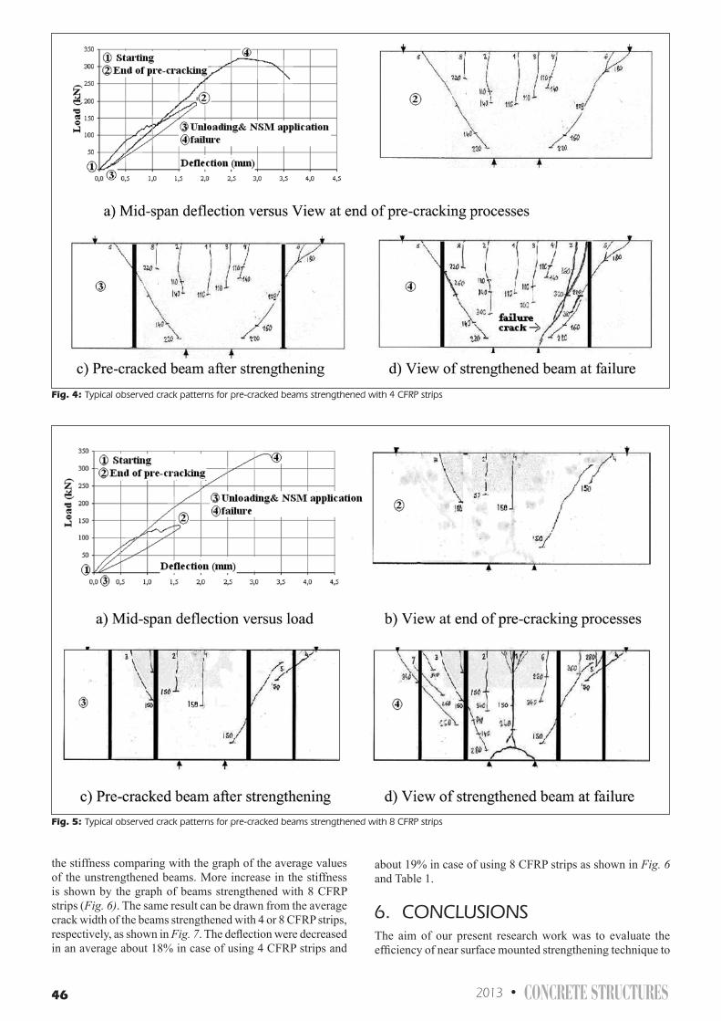
46 2013 • CONCRETE STRUCTURES
the stiffness comparing with the graph of the average values of the unstrengthened beams. More increase in the stiffness is shown by the graph of beams strengthened with 8 CFRP strips (Fig. 6). The same result can be drawn from the average crack width of the beams strengthened with 4 or 8 CFRP strips, respectively, as shown in Fig. 7. The deflection were decreased in an average about 18% in case of using 4 CFRP strips and
about 19% in case of using 8 CFRP strips as shown in Fig. 6 and Table 1.
6. CONCLUsIONsThe aim of our present research work was to evaluate the efficiency of near surface mounted strengthening technique to
Fig. 4: Typical observed crack patterns for pre-cracked beams strengthened with 4 CFRp strips
Fig. 5: Typical observed crack patterns for pre-cracked beams strengthened with 8 CFRp strips

CONCRETE STRUCTURES • 2013 47
increase shear capacity. The experimental study resulted the following conclusions.
a) The strengthening technique prevented the propagation of the existing cracks while several new cracks were developed upon the uncracked beam surface. The newly developed cracks together with the already existing pre-cracks, some of them,
continued propagations up to the failure of the beam (Figs. 4 and 5).
b) The strengthening technique corrected the behaviour of the pre-cracked beam to be fully activated in load bearing. The strengthened beam utilized its load bearing potential perfectly and behaved as a typical well-designed reinforced
Fig. 6: Comparison between typical graphs of deflection versus load for beams strengthened with 4 CFRp, or strengthened with 8 CFRp in addition to unstrengthened beams
Fig. 7: Comparison between graphs of average crack width versus load for beams strengthened with 4 CFRp and strengthened with 8 CFRp
Table. 1: Comparison of deflection values at some load levels for all beams
Beam description
Beam group Unstrengthened beams Beams strengthened with 4CFRP
Beams strengthened with 8CFRP
Beam number 1 2 3 1 2 3 1 3 Deflection (mm) at 100 kN 0.691 0.682 0.754 0.824 0.800 0.877 0,776 0,760
Ratio to average values of unstrengthened beams
Average value = 0.709 -16 % -13% -23% - 9% -7 %
-17 % -8 % Deflection (mm) at 200 kN 1.789 1.864 1.914 1.550 1.709 1.675 1,606 1,558
Ratio to average values of unstrengthened beams
Average value = 1.856 16% 8% 10% 13% 16%
-12 % -14 % Deflection (mm) at 300 kN ~ 3.080 2.985 ~
3.177 2.311 2.590 2.647 2,386 2,604
Ratio to average values of unstrengthened beams
Average value = 3.081 25% 16% 14% 23% 16%
-18 % -19 % Deflection at max load (mm) 3.066 3.005 3.116 2.721 2.882 3.370 3,450 3,195
Ratio to average values of unstrengthened beams
Average value = 3.063 11% 6% -10% -11% -4%
2 % - 8 %
Failure load (kN) 299.35 301.75 297.55 324.15 319.76 337.85 338,41 341,18
Ratio to average values of unstrengthened beams
Average value = 299.55 8% 6% 11% 11% 12%
8 % 12 %
Failure mode Shear Shear Flexural

48 2013 • CONCRETE STRUCTURES
concrete beam that reached its ultimate load bearing capacity (Figs. 4 and 5).
c) The strengthening successfully prevented the propagation of the most serious shear cracks, which were developed at the pre-cracking stage, as well as successfully prevented the shear failure mode of the beam and changing it to flexural failure mode (Fig. 5).
d) The strengthening prevented significant sudden increase of the crack width for most of the pre-cracks, it confirms that the strengthening system successfully distributed the stresses along the beam length (Fig. 7).
e) The high initial gradient of the diagram of average crack width versus load means that the strengthening system prevented significant width increase of the pre-cracks up to load level more than the 60% of the failure load. However, neither propagations of the pre-cracks, nor development of new cracks was recognized up to about the 70% of the failure load. The application of 8 strengthening CFRP strips improved the load bearing capacity of beams by 12% (Fig. 6).
f) The diagram of strengthened beams goes very close to the diagram of unstrengthened beams up to load about the 40% of the failure load, then the gradient of the diagram for the unstrengthened beams is significantly decreased, while the diagram of strengthened beams keep the same gradient up to the beginning of the failure process. The applications of 8 strengthening CFRP strips produced significant stiffness improvement during the whole period of loading (Fig. 6).
7. ACKNOWLeDGeMeNTsThe authors are grateful to Sika Hungary Ltd. industrial sponsor for the support of the research.
8. ReFeReNCesAl Makt, M., Balázs, L. G., (2011), “External Shear Strengthening with CFRP
for Beams with Insufficient Internal Shear Reinforcement”, CCC2011 Proceedings, Hungary, Balatonfüred, pp. 253-256.
Cruz, J., Barros, J., (2004), “Modeling of bond between near-surface mounted CFRP laminate strips and concrete”, ELSEVIER, Computer and Structures 82 (2004), pp. 1523-1521.
Dias, S., Barros, J., (2005), “Shear Strengtening of RC Beam with Near Surface- Mounted CFRP laminates”, FRPRCS-7, Proceedings, New Orleans, Louisiana, USA. pp. 807-828.
Lorenzis, L., Nanni A., (2002), “Bond between Near-Surface Mounted Fiber-Reinforced Polymer Rods and Concrete in Structural Strengthening”, ACI Structural Journal, March- April 2002, pp. 123-132.
Lorenzis, L., (2004), “ Anchorge Length of Near- Surface Mounted Fiber-Reinforced Polymer Rods and Concrete in Structural Strengthening- Analytical Modeling”, ACI Structural Journal, May- June 2004, pp. 375-386
Rizzo, A., Lorenzis, L., (2009), “Behavior and capacity of RC beams strengthened in Shear with NSM FRP reinforcement”, ELSEVIER, Construction and Building Materials, 23 (2009), pp. 1555-1567.
Wang, B., Teng, J. G., Lorenzis, L., Zhou, L., Ou, L., Jin, W., Lau, K. T., (2009), “Strain monitoring of RC members strengthened with smart NSM bars” , ELSEVIER, Construction and Building Materials, 23 (2009), pp. 1698-1711.
Mazen Al Makt (1963) Syria. Electrical Engineering, Damascus University (1983). B.Sc. Civil Engineering, BME (1989). M.Sc. Structural Engineering, BME (1993). Site engineer, United Arab Emirates (UAE) (1995). Research work, TEMPUS project, Sheffield University, UK (1999). Ph.D. research work and studies, field of strengthening, BME, Hungary (2001). President of Engineering Office, Contracting Company, Hungary (2007). Technical Responsible Director, Investing and Contracting Company, Hungary (2009). Technical general Director, Contracting Company, Hungary (2010). Ph.D. research work and studies, field of strengthening using non metallic reinforcement (2011). Member of Hungarian Group of (fib). President of Engineering Association for Syrian Engineers in Hungary.
Prof. György L. Balázs (1958), Civil Engineer, PhD, Dr.-habil., professor of structural engineering, head of Department of Construction Materials and Engineering Geology at the Budapest University of Technology and Economics (BME). His main fields of activities are experimental investigation and modeling of RC, PC, FRC structures, HSC, fire resistance of concrete. He is chairman of several commissions and task groups of fib. He is president of Hungarian Group of fib, editor-in-chief of the journal Concrete Structures. He was elected as President of fib at the Washington fib Congress and performed this function in 2011-2012, and accordingly he is present time Immediate Past President of the international organization.