httf scoping calculations - idaho national laboratory documents... · outline • scoping analysis...
TRANSCRIPT

International RELAP5 Users Group Seminar September 12-13, 2013 Idaho Falls, Idaho
Paul D. Bayless Idaho National Laboratory
HTTF Scoping Calculations
Outline • Scoping analysis objectives • HTTF description • RELAP5-3D input model description • System heatup simulations • System cooldown simulations • System reheat simulations • Summary
2
High Temperature Test Facility (HTTF) • Integral experiment being built at Oregon State University • Electrically-heated, scaled model of a high temperature gas
reactor – Reference is the MHTGR (prismatic blocks) – Large ceramic block representing core and reflectors – ¼ length scale – Prototypic coolant inlet (259°C) and outlet (687°C) temperatures – Less than scaled power – Maximum pressure of ~700 kPa
• Primary focus is on depressurized conduction cooldown transient
3
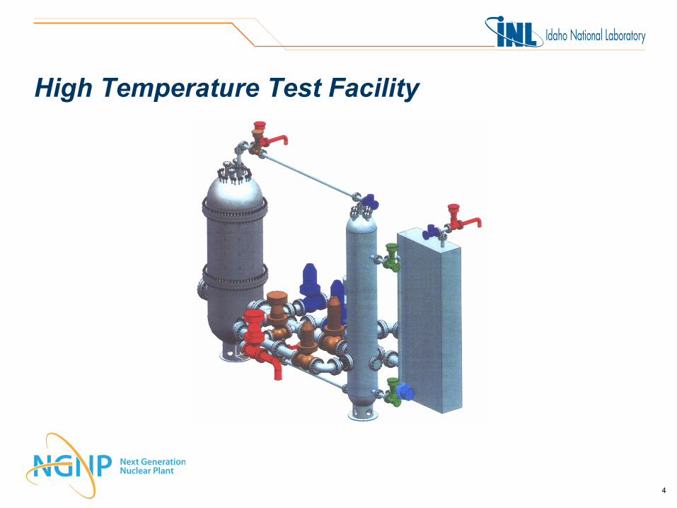
High Temperature Test Facility
4
Scoping Analysis Objectives • Investigate some simple approaches to normal plant operational
evolutions • Determine approximate timing • Estimate resource requirements • Get a feel for the overall system response
5

High Temperature Test Facility (HTTF) RELAP5-3D Input Model Description • Four systems – Primary coolant – Secondary coolant – Reactor cavity – Reactor cavity cooling system (RCCS)
• Central and side reflector regions divided into regions with or without coolant holes
• 2-D (radial/axial) conduction in all vertical heat structures • Heater block unit cell centered on the coolant channel • Radial conduction and radiation inside core barrel • Radiation from core barrel to vessel to RCCS
6

Reactor Vessel Nodalization • Multiple flow paths through core – Three heated channels – Central reflector – Side reflector
• Gaps on either side of permanent side reflector not flow-through
• Riser annulus between core barrel and pressure vessel
• No coolant between upper plenum shield and upper head
7

HTTF RELAP5-3D Core Region Radial Nodalization Reactor vessel
Core barrel
Coolant
Central reflector
Core region
Permanent reflector
Coolant gaps Heater rod Coolant hole
Side reflector
8
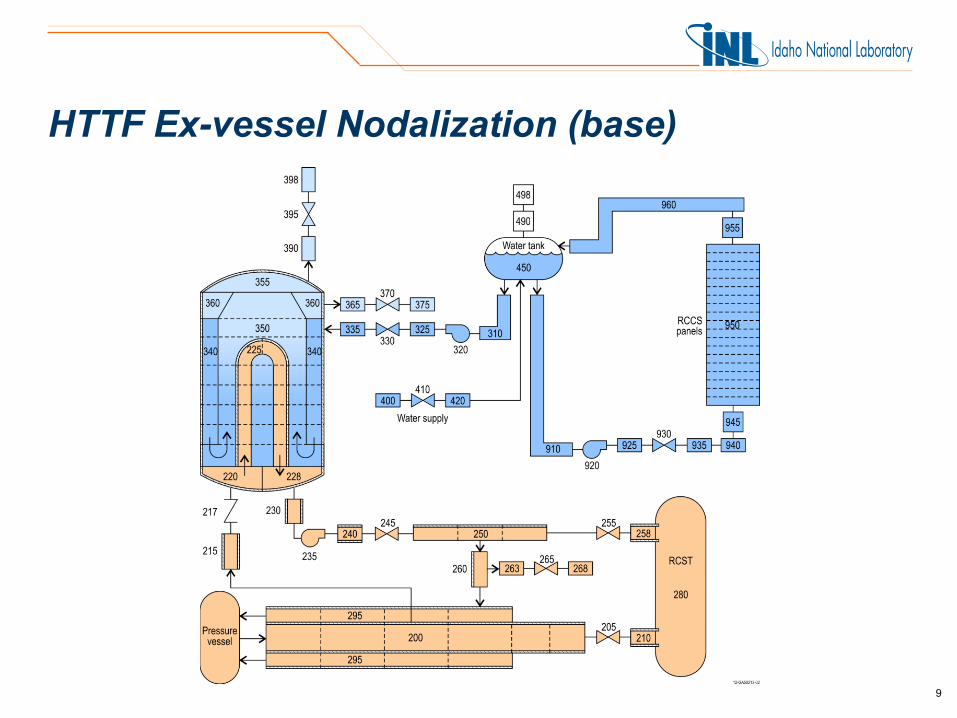
HTTF Ex-vessel Nodalization (base)
9

HTTF Ex-vessel Nodalization (modified)
10

Initial Heatup Calculations • Entire system at ambient temperature (28°C) and pressure • Steam generator secondary full of air • Core ceramic heatup rate limited to 55.6°C/h • Principal interest is steam generator response – Minimize steaming – Maintain tube integrity
• Approach – Start feedwater flow before tubes reach saturation temperature – Use compressor only for initial heatup – Maximum allowed heatup rate
11

Initial Heatup Boundary Conditions • Primary helium flow of 1.0 kg/s • Feedwater flow – 0.01 kg/s starting when tubes approach saturation temperature – Controlled to maintain vessel inlet temperature of 258.6°C
• Constant RCCS flow of 0.5 kg/s of 17°C water • Ambient heat loss only modeled on back side of RCCS panels
12

Initial Heatup Core Temperatures
13

Initial Heatup Reflector Temperatures
14

Initial Heatup Outer Structure Temperatures
15

Initial Heatup Steam Generator Tube Temperatures
16
Upflow side Downflow side

Initial Heatup System Pressures
17

Initial Heatup Heater Rod Power
18
System Heatup Observations • Heater rods reach full power in 17 hours • Full heatup will take about 24 hours • Temperatures may be close enough after 21 hours • Portions of the steam generator tubes are uncovered • Steam generator uses about 35,000 kg (9,300 gal) of water • Heater rods require about 25,000 kWh • More helium needed to reach operating pressure
19
System Cooldown Calculations • Begins after a 2-day depressurized conduction cooldown (DCC)
test – Turn power off, close break valves, open loop isolation valve
• Controlled cooldown – 55.6°C/h maximum ceramic cooldown rate – Primary control through primary coolant flow rate
• Walk-away – Break valves stay open – No feedwater or RCCS flow
• Maximum cooldown – Ignores cooldown rate limitation
20

Controlled Cooldown Core Temperatures
21

Controlled Cooldown Reflector Temperatures
22
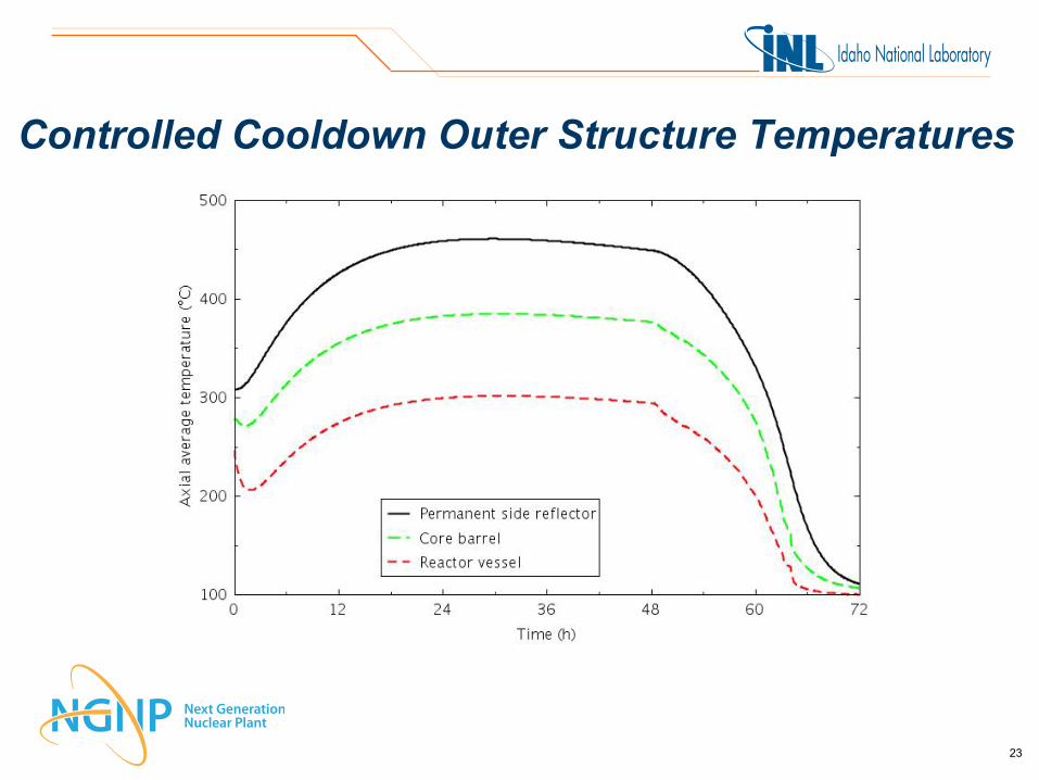
Controlled Cooldown Outer Structure Temperatures
23
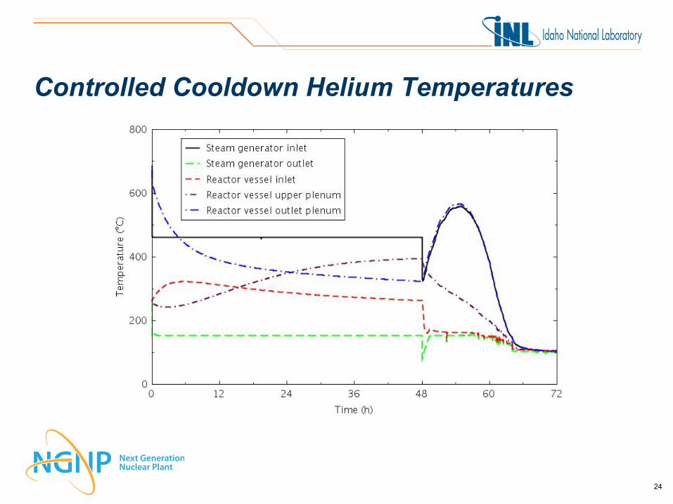
Controlled Cooldown Helium Temperatures
24

Controlled Cooldown System Pressures
25

Walk-away Cooldown Reflector Temperatures
26

Maximum Cooldown Reflector Temperatures
27

System Cooldown Observations • Cooldown at the maximum rate will take about 24 hours, using
about 11,000 kg (2,800 gal) of water • Cooling down by turning the power off and walking away will
take about 3 weeks • At full primary coolant flow, cooldown would take about 12 hours,
using about 9,300 kg (2,500 gal) of water • For forced flow cooldown cases, the steam generator secondary
limits the ultimate temperature
28

System Reheat Calculations • Begins after a 2-day DCC test – Turn power off, close break valves, open loop isolation valve
• One-hour cooldown to re-introduce hot helium to steam generator tubes
• Reheat at 55.6°C/h in the core ceramic • Feedwater controlled to maintain nominal vessel inlet helium
temperature • Helium added to repressurize primary system
29

System Reheat Core Temperatures
30

System Reheat Reflector Temperatures
31
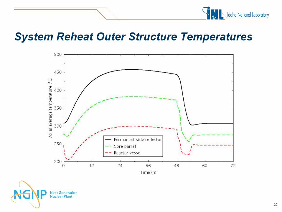
System Reheat Outer Structure Temperatures
32
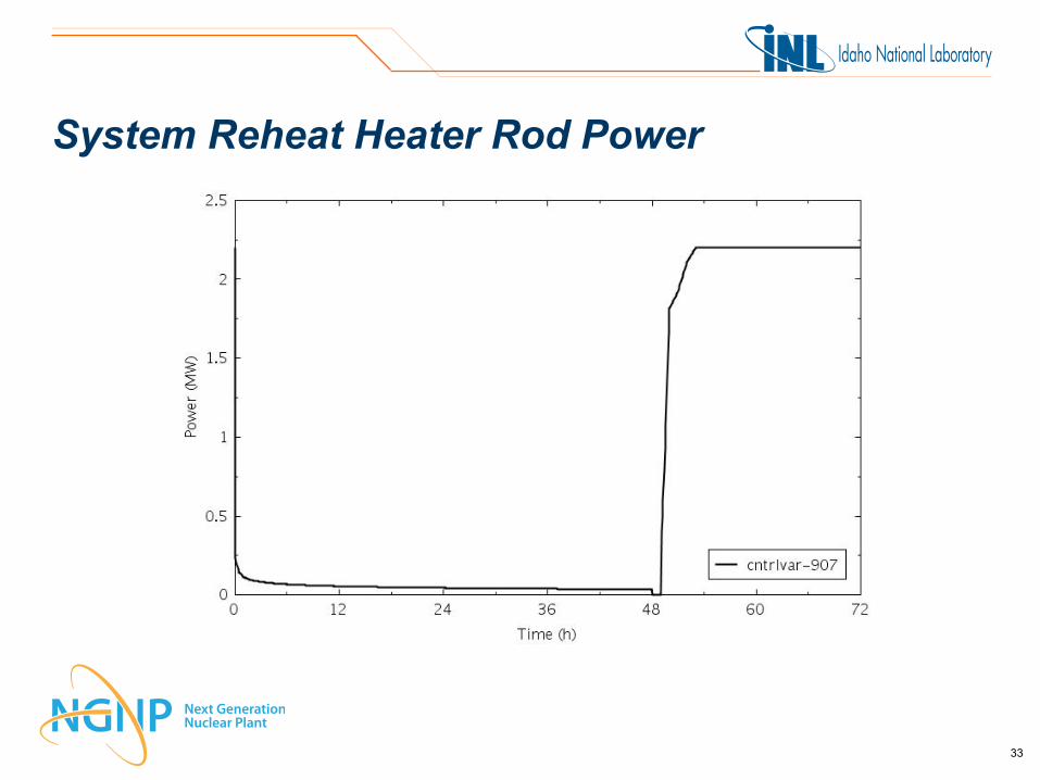
System Reheat Heater Rod Power
33

System Reheat Observations • Initial need is to cool the system • There may be a window in which the system can be recovered
relatively quickly
34

Summary • Simulations of plant operational evolutions have been performed • Evolutions were not optimized • Initial system heatup – Takes about 1 day – Steam generator tubes are partially uncovered
• System cooldown – Takes about 1 day at the maximum cooldown rate – Takes about 3 weeks if left alone – Might be cooled down in about 12 hours in an emergency
• System reheat – Might be able to be accomplished in 12 hours or less
35