htr systems and components - atoms for peace and · pdf filehtr systems and components dr....
TRANSCRIPT
Dr. Brinkmann / D. Vanvor, IAEA Course on HTR Technology,Beijing,22-26.October 2012 Page 1
HTR Systems and Components
Dr. Gerd Brinkmann
Dieter Vanvor
AREVA NP GMBH
Henry-Dunant-Strasse 50
91058 Erlangen
phone +49 9131 900 96840/95821
fax +49 9131 900 94166
mail: [email protected]
mail: [email protected]
IAEA Course on HTR Technology
Beijing, 22-26.October 2012

Dr. Brinkmann / D. Vanvor, IAEA Course on HTR Technology,Beijing,22-26.October 2012 Page 2 2
Pebble Bed Reactor Block Reactor

Dr. Brinkmann / D. Vanvor, IAEA Course on HTR Technology,Beijing,22-26.October 2012 Page 3 3
HTR with Steam Generator/IHX
Pebble Bed Reactor and Bock Reactor with SG
Common: RPV, Cross Vessel, SG Vessel
Steam Generator (more or less)
Circulator (more or less)
Rods (more or less)
Cavity Cooling System (more or less)
Helium Auxiliary Systems (more or less)
Hot Gas Duct (more or less)
Different: Fuel Handling Systems
Shut Down Cooling System
Pebble Bed Reactor and Bock Reactor with IHX
IHX and Isolating Valve
Dr. Brinkmann / D. Vanvor, IAEA Course on HTR Technology,Beijing,22-26.October 2012 Page 4 4
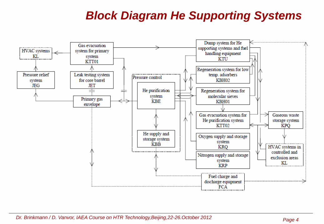
Block Diagram He Supporting Systems

Dr. Brinkmann / D. Vanvor, IAEA Course on HTR Technology,Beijing,22-26.October 2012 Page 5 5
Requirements of Helium Auxiliary Systems

Dr. Brinkmann / D. Vanvor, IAEA Course on HTR Technology,Beijing,22-26.October 2012 Page 6 6
He-Purification System KBE

Dr. Brinkmann / D. Vanvor, IAEA Course on HTR Technology,Beijing,22-26.October 2012 Page 7 7
Components for retention of impurities

Dr. Brinkmann / D. Vanvor, IAEA Course on HTR Technology,Beijing,22-26.October 2012 Page 8 8
Anticipated values for normal operation

Dr. Brinkmann / D. Vanvor, IAEA Course on HTR Technology,Beijing,22-26.October 2012 Page 9 9
Hot Gas Duct
Parameters for design selection:
• Maximum heat loss for the hot gas ducts
• Helium flow rate inside the hot gas ducts
• Geometric dimensions of the pressure vessel
• Maximum differential pressure for the support pipe
• Maximum depressurization rate for the hot gas side
• Maximum temperature variations
• Movements to be compensated in the axial and vertical directions
• Planned inspections
• Concept for disassembling and assembling after start of nuclear operation

Dr. Brinkmann / D. Vanvor, IAEA Course on HTR Technology,Beijing,22-26.October 2012 Page 10 10
Hot Gas Duct: metallic version
Radial layout:
- Liner as a closed metal cylinder
- Depressurization gap for controlled discharge of gas volume from fibrous fill on
decompression
- Perforated pipe with mesh cover enclosing the insulant space
- Wrapped fiber mat insulation made of 95% alumina and 5% silica
- Intermediate layer of metal foil to reduce free convection volume
- Wrapped fiber mat insulation made of 95% alumina and 5% silica
- Support pipe housing the internals and serving as pressure boundary between
hot and cold gas channels
Axially this arrangement is interrupted approx. every 1000 mm by a vee-shaped
spacer. These metallic thermosleeves have the task of supporting the internal
flow guides and preventing axial flow through the insulation. The insulant is
packed in the region of the vee-shaped spacers. The layout has been qualified
by test components with original dimensions in the component testing facility
KVK.

Dr. Brinkmann / D. Vanvor, IAEA Course on HTR Technology,Beijing,22-26.October 2012 Page 11 11
Hot Gas Duct: metallic version
Material Specifications:
Liner, hot side of vee 1.4876 (X10NiCrAlTi32-21 / X10NiCrAlTi32-20)
and depressurization gap tube
Support pipe and cold side of vee 1.4571 (X6CRNIMOTI17-12-2) with specified cobalt content of maximum 300 ppm
Packed fibre insulation pads made of long fibre mats with 95% al2o3 + 5% sio2
Wrapped fibre insulation fibre-mats made of long fibre with 95% Al2O3 + 5% SiO2

Dr. Brinkmann / D. Vanvor, IAEA Course on HTR Technology,Beijing,22-26.October 2012 Page 12 12
Hot Gas Duct: metallic version
Pictures from manufacturing
Horizontal test tube
outer diameter 1220 mm
wall thickness 30 mm
flow diameter 700 mm
90° elbow test tube
outer diameter 1320 mm
wall thickness 50 mm
flow diameter 700 mm

Dr. Brinkmann / D. Vanvor, IAEA Course on HTR Technology,Beijing,22-26.October 2012 Page 13 13
Hot Gas Duct: ceramic version
Radial layout :
- Liner as a closed graphite or cfc cylinder
- No depressurization gap because the liner can withstand about 90 bar differential
pressure
- Wrapped fiber mat insulation made of 95% alumina and 5% silica
- Intermediate layer of graphite foil to reduce free convection volume and axial flow
through the insulation
- Wrapped fiber mat insulation made of 95% alumina and 5% silica
- Support pipe housing the internals and serving as pressure boundary between
hot and cold gas channels
Axially this arrangement is interrupted approx. every 1000 mm of maximum liner-
tube length. Because there are no thermosleeves to preventing axial flow through
the insulation such as are used in the metallic version, several graphite foils
(approx. every 10 mm) in the insulation provide a large pressure drop in the axial
direction. The insulant is packed in the region of the ceramic spacers. The layout
has been qualified by test components with original dimensions in the test facility
KVK

Dr. Brinkmann / D. Vanvor, IAEA Course on HTR Technology,Beijing,22-26.October 2012 Page 14 14
Hot Gas Duct: ceramic version
Material Specifications:
Liner Graphite type ASR-1RG, carbon fibre composite (CFC)
Radial and axial ceramic spacers Al2O3 ceramic, under pressure from all sides
Packed fibre insulation pads made of long fibre mats with 95% Al2O3 + 5% SiO2
Wrapped fibre insulation fibre-mats made of long fibre with 95% Al2O3 + 5% SiO2
Support pipe 1.4571 (X6CrNiMoTi17-12-2) with specified cobalt content
of maximum 300 ppm

Dr. Brinkmann / D. Vanvor, IAEA Course on HTR Technology,Beijing,22-26.October 2012 Page 15 15
Hot Gas Duct: ceramic version
Pictures from manufacturing
Horizontal test tube
outer diameter 1020 mm
wall thickness 20 mm
flow diameter 700 mm Core Connection
System test tube
flow diameter 700 mm

Dr. Brinkmann / D. Vanvor, IAEA Course on HTR Technology,Beijing,22-26.October 2012 Page 16 16
Active Cavity Cooling System (Water)

Dr. Brinkmann / D. Vanvor, IAEA Course on HTR Technology,Beijing,22-26.October 2012 Page 17 17
Active Cavity Cooling System (Water)

Dr. Brinkmann / D. Vanvor, IAEA Course on HTR Technology,Beijing,22-26.October 2012 Page 18 18
Passive Cavity Cooling System (Water)

Dr. Brinkmann / D. Vanvor, IAEA Course on HTR Technology,Beijing,22-26.October 2012 Page 19 19
Passive Cavity Cooling System (Air)
Dr. Brinkmann / D. Vanvor, IAEA Course on HTR Technology,Beijing,22-26.October 2012 Page 20 20
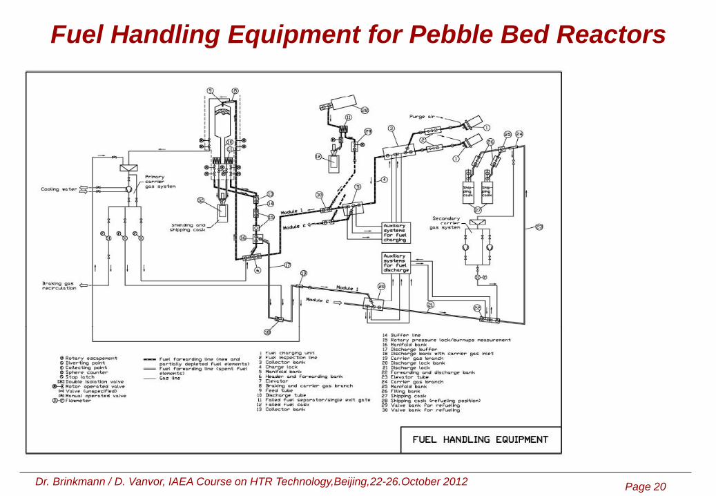
Fuel Handling Equipment for Pebble Bed Reactors

Dr. Brinkmann / D. Vanvor, IAEA Course on HTR Technology,Beijing,22-26.October 2012 Page 21 21
Fuel Handling Equipment for Pebble Bed Reactors
Test facility of core discharging device
On-site test of outside fuel counter

Dr. Brinkmann / D. Vanvor, IAEA Course on HTR Technology,Beijing,22-26.October 2012 Page 22 22
Fuel Handling Equipment for Block Reactors

Dr. Brinkmann / D. Vanvor, IAEA Course on HTR Technology,Beijing,22-26.October 2012 Page 23 23
Fuel Handling Equipment for Block Reactors

Dr. Brinkmann / D. Vanvor, IAEA Course on HTR Technology,Beijing,22-26.October 2012 Page 24 24
Intermediate Heat Exchanger (IHX)
1 Pressure boundary 9 Core
2 Outer liner 10 Cavity cooler
3 Outer insulation 11 Tube bundle (helix)
4 Primary cold gas gap 12 Blower
5 Tube spacer system 13 Primary hot gas duct
6 Support system 14 Secondary loop
7 Inner secondary tube
8 Insulation of inner secondary tube

Dr. Brinkmann / D. Vanvor, IAEA Course on HTR Technology,Beijing,22-26.October 2012 Page 25 25
Test Facility KVK
Thermal power 10 MW
He-temperature 950 °C
Operating-pressure 40 bar
He-flow 3 kg/s
He-velocity 60 m/s
Temperature transients ± 200 K/min
Pressure-transient - 5 bar/s
Operation time:
> 900 °C ~ 7.000 h
> 700 °C ~ 12.000 h

Dr. Brinkmann / D. Vanvor, IAEA Course on HTR Technology,Beijing,22-26.October 2012 Page 26 26
Test Facility KVK, flow sheet with test positions

Dr. Brinkmann / D. Vanvor, IAEA Course on HTR Technology,Beijing,22-26.October 2012 Page 27 27
Intermediate Heat Exchanger (IHX)
The helium gas intermediate heat exchanger is subject to a maximum helium
inlet temperature of 950°C on the primary side and 900°C on the secondary side.
The differential pressure across the tube wall in operation is approx. 2 bar; the
secondary-side pressure is maintained above that on the primary side to prevent
leakage of contaminated helium.
Only during a sudden loss of secondary-side pressure accident could the tube
wall be exposed to full primary-side pressure for a brief period of time.
The helical tube heat exchanger is to be kept as compact as possible and should
have an economical design lifetime of 105 h. The following data are possible:
Thermal duty 170 MW
Number of tubes 2000
Tube dimensions 22 mm x 2 mm
Tube length 100 m
Bundle length 17,700 mm
Bundle diameter 3,000 mm

Dr. Brinkmann / D. Vanvor, IAEA Course on HTR Technology,Beijing,22-26.October 2012 Page 28 28
Intermediate Heat Exchanger (IHX)
Flow through the helical tube heat exchanger is with primary gas passing through
the exterior of the tube bundle and secondary gas passing through the helically
wound tubes. The tubes are held by the upper tubesheet which also forms the
channel head for the cold secondary helium. A central return channel (in principle a
vertical hot gas pipe) is shaped at the bottom like a header (hot gas header). All
heat exchanger tubes are welded ito this header. Support stars which provide
variable tube guidance are arranged at several vertical levels within the tube
bundle. The primary hot helium passes from below into the component and exits at
a relatively low temperature (approx. 300°C) between the pressure vessel and an
inner gas guide and is returned to the blower.
This compact design permits heat fluxes of about 50 kW/m2. The maximum tube
wall temperature is approx. 920°C and therefore material IN 617 can be used for the
hot piping and also for the header.
A prototype heat exchanger with a thermal duty of 10 MW was constructed and
tested at the KVK test rig; the hot gas header was modeled full scale, i.e. for 170
MW.

Dr. Brinkmann / D. Vanvor, IAEA Course on HTR Technology,Beijing,22-26.October 2012 Page 29 29
Intermediate Heat Exchanger (IHX)
Helix type, pictures from manufacturing

Dr. Brinkmann / D. Vanvor, IAEA Course on HTR Technology,Beijing,22-26.October 2012 Page 30 30
Isolation Valves (secondary side)
In indirect-cycle units the nuclear-generated heat is extracted from the coolant by a
gas-filled secondary cycle comprising plant equipment which is independent from
the reactor plant (e.g. intermediate heat exchanger). For this purpose the
secondary gas must be forwarded from the reactor system to the connected heat
sink through an internally insulated pipe and returned by way of an externally
insulated pipe.
In the case of the larger-diameter secondary-side piping both the cold-leg and the
hot-leg piping have to be run within the reactor plant to the intermediate heat
exchanger As a result of this configuration the requirement exists that isolation of
this piping must be possible in the area of the confinement penetrations so as to
ensure safe confinement of radioactivity.
The valves needed for the cold-leg piping (approx. 350°C) are not discussed as
these are essentially conventional items. However, no commercially available
valves are capable of fulfilling the specific requirements applicable to the hot-leg
valves. For this reason the axial valve adopted as preference by Siemens in the
course of HTR Module development.

Dr. Brinkmann / D. Vanvor, IAEA Course on HTR Technology,Beijing,22-26.October 2012 Page 31 31
Isolation Valves (secondary side)
Design Features of RCS Isolation Valves
In the course of the above-mentioned development project the following main
design data and operating data were established for the secondary-side hot gas
valves. Most of these specifications can be applied unchanged to new projects:
Operating pressure 41.9 bar
Hot gas temperature 900 ±18°C
Body design temperature (pressure boundary) 400°C
Helium mass flow 47.3 kg / s
Temperature transient (startup and shutdown) ± 2 K / min
Total closing time 5 s
Max. p across seat 42 bar
Max. p during opening and closing 3.5 bar (maximum backpressure to be
overcome)
Leakage rate from both seats 1 mbarl / s (cf. Section 3.5)
Design lifetime 140,000 h
Prototype dimensions:
Pressure-retaining pipe Dia. 1,120 mm, t = 30 mm
Free flow cross section Dia. 700 mm
Total length 2,400 mm

Dr. Brinkmann / D. Vanvor, IAEA Course on HTR Technology,Beijing,22-26.October 2012 Page 32 32
Isolation Valves (secondary side)

Dr. Brinkmann / D. Vanvor, IAEA Course on HTR Technology,Beijing,22-26.October 2012 Page 33 33
Isolation Valves (secondary side)
Axial valve type,
pictures from
manufacturing

Dr. Brinkmann / D. Vanvor, IAEA Course on HTR Technology,Beijing,22-26.October 2012 Page 34 34
Isolation Valves (secondary side)
Animation of the cones

Dr. Brinkmann / D. Vanvor, IAEA Course on HTR Technology,Beijing,22-26.October 2012 Page 35 35
Isolation Valves (secondary side)
Animation of the cones inside
the valve