basic components of spectroscopic...
TRANSCRIPT

Ahmad Aqel IfseisiAssistant Professor of Analytical Chemistry
College of Science, Department of Chemistry
King Saud University
P.O. Box 2455 Riyadh 11451 Saudi Arabia
Building: 05, Office: AA53
Tel. 014674198, Fax: 014675992
Web site: http://fac.ksu.edu.sa/aifseisi
E-mail: [email protected]
Basic Components of Spectroscopic
Instrumentation

Basic components of spectroscopic
instruments
- A source of energy that can be input to the sample.
- A means for isolating a narrow range of wavelengths.
- Sample container.
- A detector for measuring the signal.
- A signal processor to display the signal in a form convenient for the analyst.

Sources of Energy
The sources of energy could be in different forms:
(1) Sources of electromagnetic radiation (photons)
A source of electromagnetic radiation must provide an output that is both intense
and stable in the desired region of the electromagnetic spectrum.
The energy levels have well-defined values (i.e., they are quantized). Absorption
only occurs when the photon’s energy matches the difference in energy, ΔE,between two energy levels.
Simplified energy level diagram
showing absorption of a photon ΔE = E1 - E0

Sources of electromagnetic radiation are classified as:
- Continuum source: a source that emits radiation over a wide range of
wavelengths.
- Line source: a source that emits radiation at only select wavelengths
(narrow wavelength ranges).
A list of the most common sources of electromagnetic radiation.
Source Wavelength region Useful for
H2 and D2 lamp continuum source from 160–380 nm UV molecular absorption
Tungsten (W) lamp continuum source from 320–2400 nm Vis molecular absorption
Xe arc lamp continuum source from 200–1000 nm molecular fluorescence
Nernst glower continuum source from 0.4–20 µm IR molecular absorption
Globar continuum source from 1–40 µm IR molecular absorption
Nichrome wire continuum source from 0.75–20 µm IR molecular absorption
Hollow cathode lamp line source in UV/Vis atomic absorption
Hg vapor lamp line source in UV/Vis molecular fluorescence
Laser line source in UV/Vis atomic and molecular absorption,
fluorescence and scattering

(2) Sources of thermal energy
The most common sources of thermal energy are flames and plasmas.
-Flame sources use the combustion of a fuel and an oxidant such as acetylene
and air, to achieve temperatures of 2000–3400 K.
-Plasmas, which are hot, ionized gases, provide temperatures of 6000–10000 K.
(3) Chemical sources of energy
Exothermic reactions also may serve as a source of energy.
In chemiluminescence the analyte is raised to a higher-energy state by means of
a chemical reaction, emitting characteristic radiation when it returns to a lower-
energy state. When the chemical reaction results from a biological or enzymatic
reaction, the emission of radiation is called bioluminescence.
Commercially available “light sticks,
glow” and the flash of light from a firefly
are examples of chemiluminescence
and bioluminescence, respectively.

Wavelength Selection
Wavelength selector is a component used to select and isolate the required
wavelengths or range of wavelengths where the analyte is the only
absorbing species (to obtain a certain wavelength or a narrow band of
wavelengths).
The ideal wavelength selector has a high throughput of radiation and a
narrow effective bandwidth. A high throughput is desirable because more
photons pass through the wavelength selector, giving a stronger signal with
less background noise. A narrow effective bandwidth provides a higher
resolution, with spectral features separated by more than twice the effective
bandwidth being resolved.

Unfortunately, we cannot isolate a single
wavelength of radiation from a continuum
source. Instead, a wavelength selector passes
a narrow band of radiation characterized by a
nominal wavelength, an effective bandwidth,
and a maximum throughput of radiation. The
effective bandwidth is defined as the width of
the radiation at half the maximum throughput.
Generally these two features of a wavelength selector are in opposition. Conditions
favoring a higher throughput of radiation usually provide less resolution. Decreasing
the effective bandwidth improves resolution, but at the cost of a noisier signal. For a
qualitative analysis, resolution is generally more important than the throughput of
radiation; thus, smaller effective bandwidths are desirable. In a quantitative analysis
a higher throughput of radiation is usually desirable.
Nominal wavelength: the wavelength which a wavelength selector is set to pass.
Effective bandwidth: the width of the band of radiation passing through a
wavelength selector measured at half the band’s height.
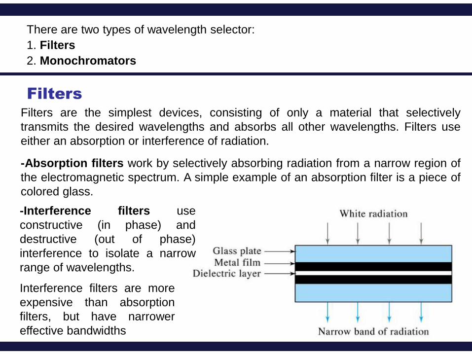
There are two types of wavelength selector:
1. Filters
2. Monochromators
Filters
Filters are the simplest devices, consisting of only a material that selectively
transmits the desired wavelengths and absorbs all other wavelengths. Filters use
either an absorption or interference of radiation.
-Interference filters use
constructive (in phase) and
destructive (out of phase)
interference to isolate a narrow
range of wavelengths.
-Absorption filters work by selectively absorbing radiation from a narrow region of
the electromagnetic spectrum. A simple example of an absorption filter is a piece of
colored glass.
Interference filters are more
expensive than absorption
filters, but have narrower
effective bandwidths

Monochromators
If measurements need to be made at two different wavelengths, then the filter must
be changed in between measurements. absorption or interference filter do not allow
for a continuous selection of wavelength.
Monochromators can give a much narrower range of wavelengths and are easily
adjustable over a wide spectral range (scan spectrum, vary continuously).
The dispersing element may be a prism or a grating.
The radiation is collected by a collimating mirror, which reflects a parallel beam of
radiation to a diffraction grating. The diffraction grating is an optically reflecting
surface with a large number of parallel grooves. Diffraction by the grating disperses
the radiation in space, where a second mirror focuses the radiation onto a planar
surface containing an exit slit.
As a result, a polychromatic source of radiation at the entrance slit is converted at
the exit slit to a monochromatic source of finite effective bandwidth.
The choice of which wavelength exits the monochromator is determined by rotating
the diffraction grating. A narrower exit slit provides a smaller effective bandwidth and
better resolution, but allows a smaller throughput of radiation.

Collimating
mirror
Light
source
Focusing
mirrorTypes of
monochromators:
Grating
monochromator
Prism
monochromator

Interferometers
An interferometer provides an alternative approach for wavelength selection.
Instead of filtering or dispersing the electromagnetic radiation, an interferometer
simultaneously allows source radiation of all wavelengths to reach the detector.
Michelson
interferometer
(beam splitter)
One fixed mirror and the
other mirror is moving
sample

Radiation from the source is focused on a beam splitter that transmits half of the
radiation to a fixed mirror, while reflecting the other half to a movable mirror. The
radiation recombines at the beam splitter, where constructive and destructive
interference determines, for each wavelength, the intensity of light reaching the
detector.
As the moving mirror changes position, the wavelengths of light experiencing
maximum constructive interference and maximum destructive interference also
changes. The signal at the detector shows intensity as a function of the moving
mirror’s position, expressed in units of distance or time. The result is called an
interferogram, or a time domain spectrum. The time domain spectrum is converted
mathematically, by a process called a Fourier transform, to the normal spectrum
(also called a frequency domain spectrum) of intensity as a function of the
radiation’s energy.
Since it does not use slits and has fewer optical components from which radiation
can be scattered and lost, interferometers provide higher throughput of source
radiation than monochromators. Furthermore, since all frequencies are monitored
simultaneously, an entire spectrum can be recorded at significantly lower time in
compared with monochromators.

Sample Containers (Holders)
The cells or cuvettes that hold the samples must be made of material that is
transparent to radiation in the spectral region of interest. Sample containers should
also in compatible with the sample type, size and state (solid, solution and gas).
Quartz or fused silica is required for work
in the ultraviolet region (below 350 nm),
both of these substances are transparent
in the visible region.
Silicate glasses can be employed in the
region between 350 and 2000 nm.
Plastic containers can be used in the
visible region.
Crystalline NaCl is the most common cell
windows in the IR region.

Detectors
The first detector for optical spectroscopy was the human eye
(limited to Visible region, limited accuracy and sensitivity to
electromagnetic radiation).
Modern detectors use a sensitive transducer to convert a signal consisting of
photons into an easily measured electrical signal.
Transducer: a device that converts a chemical or physical property, such as pH or
photon intensity, to an easily measured electrical signal, such as a voltage or current.
Device converts a signal in
one form of energy to
another form of energy.

The photoelectric effect is the observation that
many metals (such as alkali metals
or semiconductor material such as gallium
arsenide) emit electrons when light shines upon
them. Electrons emitted in this manner can be
called photoelectrons.
Incoming
light
Metal
Ejected
electrons

Photon transducer
Phototubes and photomultipliers contain a photosensitive surface that absorbs
radiation in the ultraviolet, visible, and near infrared (IR), producing an electric
current proportional to the number of photons reaching the transducer.
Other photon detectors use a semiconductor as the photosensitive surface. When
the semiconductor absorbs photons, valence electrons move to the
semiconductor’s conduction band, producing a measurable current.
Thermal transducer
Infrared radiation generally does not have sufficient energy to produce a
measurable current when using a photon transducer. A thermal transducer,
therefore, is used for infrared spectroscopy.
A thermal detector consists of a tiny blackened surface that absorbs infrared
radiation and increases in temperature as a result. The temperature rise is
converted to an electrical signal that is amplified and measured.

dynodes Photomultiplier tubes
A photon of radiation entering the tube strikes the
cathode, causing the emission of several
electrons. These electrons are accelerated
towards the first dynode (which is 90V more
positive than the cathode). The electrons strike the
first dynode, causing the emission of several
electrons for each incident electron. These
electrons are then accelerated towards the second
dynode, to produce more electrons which are
accelerated towards dynode three and so on.
Eventually, the electrons are collected at the
anode. Each original photon produces about 106-
107 electrons.
Phototube
Vacuum phototube, which consists of a semicylindrical
cathode and a wire anode sealed inside an evacuated
transparent envelope. The concave surface of the
electrode supports a layer of photoemissive material that
tends to emit electrons when it is irradiated. When a
voltage is applied across the electrodes, the emitted
electrons flow to the wire anode generating a
photocurrent that is generally about one tenth as great
as that associated with a photovoltaic cell for a given
radiant intensity.
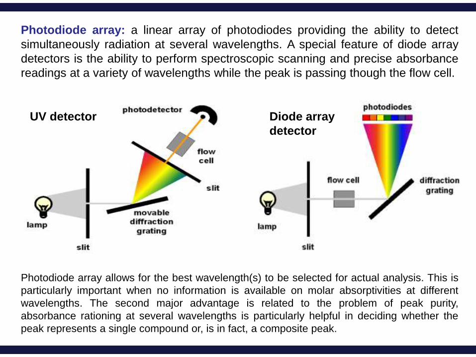
Photodiode array: a linear array of photodiodes providing the ability to detect
simultaneously radiation at several wavelengths. A special feature of diode array
detectors is the ability to perform spectroscopic scanning and precise absorbance
readings at a variety of wavelengths while the peak is passing though the flow cell.
Photodiode array allows for the best wavelength(s) to be selected for actual analysis. This is
particularly important when no information is available on molar absorptivities at different
wavelengths. The second major advantage is related to the problem of peak purity,
absorbance rationing at several wavelengths is particularly helpful in deciding whether the
peak represents a single compound or, is in fact, a composite peak.
Diode array
detector
UV detector

Detector Wavelength range Output signal
Photon detectors
Phototube 200–1000 nm current
Photomultiplier 110–1000 nm current
Si photodiode 250–1100 nm current
Photoconductor 750–6000 nm change in resistance
Photovoltaic cell 400–5000 nm current or voltage
Thermal detectors
Thermocouple 0.8–40 µm voltage
Thermistor 0.8–40 µm change in resistance
Pneumatic 0.8–1000 µm membrane displacement
Pyroelectric 0.3–1000 µm current
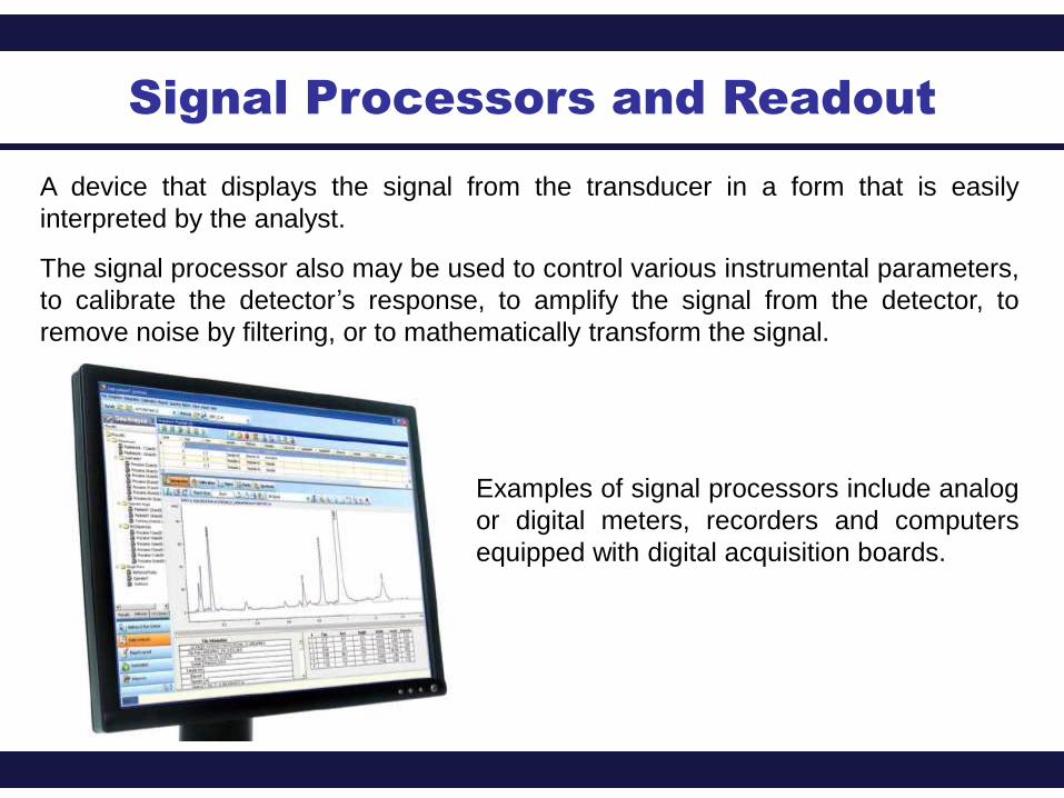
Signal Processors and Readout
A device that displays the signal from the transducer in a form that is easily
interpreted by the analyst.
The signal processor also may be used to control various instrumental parameters,
to calibrate the detector’s response, to amplify the signal from the detector, to
remove noise by filtering, or to mathematically transform the signal.
Examples of signal processors include analog
or digital meters, recorders and computers
equipped with digital acquisition boards.

Source of light
Wavelength selector
Sample DetectorSignal
processor
Basic Components of Spectroscopic Instrumentation
