hr data sheet - bel fuse€¦ · bcd.00580 rev. 003, 23-mar-2016 prelim. page 2 of 22 melcher the...
TRANSCRIPT

BCD.00580 Rev. 003, 23-Mar-2016 Prelim. Page 1 of 22MELCHERThe Power Partners.
LR Series Data Sheet210 – 300 Watt AC-DC Converters with PFC
Table of Contents Page Page
DescriptionThe LR Series of AC-DC converters represents versatile powersupplies ideally suitable for use in advanced electronicsystems. Features include full power factor correction, goodhold-up time, high efficiency and reliability, low output noise,and excellent dynamic response to load/line changes.
The converter inputs are protected against surges andtransients. An input over- and undervoltage lockout circuitry
Features
• RoHS-compliant• Class I equipment• Universal input voltage range• Inrush current limitation• 2 isolated adjustable outputs• No load, overload, and short-circuit proof• Rectangular current limiting characteristic• Inhibit function• Parallel operation with active current sharing• Hold-up time 20 ms• Designed according to EN 50155, EN 50121-4, AREMA• Fire & smoke according to EN 45545.• Immunity according to IEC 61000-4-2, -3, -4, -5, -6, -8, -9• ALL PCB boards protected by lacquer• Very high reliability
Safety-approved according to IEC/EN 60950-1, UL/CSA60950-1 2nd Ed.
disables the outputs if the input voltage is outside of thespecified range. Input inrush current limitation is included toprevent circuit breakers and fuses from tripping at switch-on.
The outputs are open- and short-circuit proof.
Full input-to-output, input-to-case, output-to-case, and outputto output isolation is provided. Particularly the outputs exhibitan extended insulation to the case. All boards are coated with aprotective lacquer.
1686.6"
803.2"16 TE
1114.4"3 U
1686.6"
602.4"12 TE
1114.4"3 U
Copyright © 2016, Bel Power Solutions Inc. All rights reserved.
Description .......................................................................... 1Model Selection .................................................................. 2Functional Description ........................................................ 4Electrical Input Data ............................................................ 5Electrical Output Data ......................................................... 6Auxiliary Functions ............................................................. 11
Electromagnetic Compatibility (EMC) ............................... 13Immunity to Environmental Conditions ............................. 15Mechanical Data ............................................................... 16Safety and Installation Instructions ................................... 19Description of Options ...................................................... 20Accessories ....................................................................... 21
Preliminar
y

BCD.00580 Rev. 003, 23-Mar-2016 Prelim. Page 2 of 22MELCHERThe Power Partners.
LR Series Data Sheet210 – 300 Watt AC-DC Converters with PFC
Model Selection
Table 1: Model Selection
Output 1 Output 2 Power Input voltage ηηηηη 1101 ηηηηη230 2 Model Opt.
Vo nom Io nom Vo nom Io nom Po nom Vi cont min. typ. min. typ.[V] [A] [V] [A] [W] [VAC] [%] [%] [%] [%]
12 10 12 10 240 90 to 264 90 LR2320-9RG F0, F2,12 12.5 12 12.5 300 LRP2320-9RG B, B115 8 15 8 240 LR2540-9RG15 10 15 10 300 LRP2540-9RG48 2.2 48 2.2 211 LR2880-9RG48 2.6 48 2.6 250 LRP2880-9RG
1 Efficiency at TA = 25 °C, Vi = 110 VAC, Io nom, Vo nom2 Efficiency at TA = 25 °C, Vi = 230 VAC, Io nom, Vo nom
The case design allows for operation at nominal load up to71 °C with natural cooling. If forced cooling is provided, theambient temperature may exceed 71 °C, but the casetemperature must remain below 95 °C.
A temperature sensor generates an inhibit signal, whichdisables the outputs when the case temperature TC exceedsthe limit. The outputs are automatically re-enabled when thetemperature drops below the limit.
LED indicators display the status of the converter and allow forvisual monitoring of the system at any time.
The converters can either be plugged into a 19 " rack systemaccording to IEC 60297-3, or be chassis mounted. Two heatsinks of different size and cooling plates for chassis mounting(option B, B1) are available.

BCD.00580 Rev. 003, 23-Mar-2016 Prelim. Page 3 of 22MELCHERThe Power Partners.
LR Series Data Sheet210 – 300 Watt AC-DC Converters with PFC
Product Marking
Basic type designation: applicable approval marks, CE mark,warnings, pin designation, patents and company logo,identification of LEDs.
Specific type designation: input voltage range, nominal outputvoltages and currents, degree of protection, batch no., serialno., and data code including production site, modificationstatus, and date of production.
Example: LR2320-9B1G: AC-DC converter, operating input voltage range 90 to 264 VAC, 2 isolated outputs, each providing12 V, 20 A, cooling plate B1, RoHS-compliant for all six substances.
Part Number Description
Operating input voltage Vi cont (continuously):
100 – 240 VAC ................................................ LR, LRP
Number of outputs ......................................................... 2, 72
Nominal voltage of main output Vo1 nom
12 V ............................................................................ 315 V ............................................................................ 524 V 4 ........................................................................................................... 636 V ............................................................................ 748 V ............................................................................ 8Other voltages 1 ........................................................... 9
Nominal voltage of tracking output Vo2 3
12 V ............................................................................ 2015 V ............................................................................ 4024 V 4 ......................................................................................................... 6036 V 4 ......................................................................................................... 7048 V ............................................................................ 80Other specifications or additional features 1 ...... 21 – 99
Operational temperature range: TA:
TA = –40 to 71 °C, TC ≤ 95 °C .................................... -9Other 1 ............................................................... -0, -5, -6
Auxiliary functions and options:
Fuse options ........................................................ F0, F2Cooling plate standard case ................................. B, B1Cooling plate for long case 220 mm 2 ...................... B2 2
RoHS-compliant for all 6 substances ..........................G
1 Customer-specific models. No safety-relevant changes compared to the respective basic model, e.g. different mechanical details,special markings, mounted front plates, reduced output voltage, etc.
2 Converters with 220 mm case (customer-specific models). Add 5000 to the model number!3 The nominal voltages of both outputs are always equal.4 Models not or not yet available
Note: The sequence of options must follow the order above.
LR 2 3 20 -9 B1 G

BCD.00580 Rev. 003, 23-Mar-2016 Prelim. Page 4 of 22MELCHERThe Power Partners.
LR Series Data Sheet210 – 300 Watt AC-DC Converters with PFC
Functional DescriptionThe input voltage is fed via an efficient filter and a bridgerectifier to the PFC-corrected step-up converter, whichgenerates the intermediate voltage across the bulk capacitorCb. The inrush current is limited by the resistor Rinr, which isshorted by Vinr, after the bulk capacitor was charged.
The bulk capacitor sources a half bridge DC-DC converter andprovides the power during the specified hold-up time.
The main transformer exhibits two secondary windings for thetwo outputs. The resultant voltages are rectified bysynchronous rectifiers (not models with Vo = 2× 48 V), in orderto provide the best efficiency. Their ripple voltages aresmoothed by a dual choke and output filters. The control logicsenses the main output voltage Vo1 and generates the gatesignals for the DC-DC converter, which are transferred byisolated drivers to the primary side.
The second output is tracking the main output voltage, but hasits own current limiting circuit. If the main output voltage drops
Fig. 1Block diagram
due to current limitation, the second output voltage will drop aswell and vice versa.
The output voltages can be adjusted by external means.Parallel operation of several converters is possible byconnecting the T-pins together in order to provide activecurrent sharing. Both outputs can be connected in parallel or inseries. They exhibit a rectangular current limitation cha-racteristic. Switchable preloads ensure good regulation evenwith no load at one output.
A control output (D) and two LEDs signal correct operation ofthe converter. In case of an output overvoltage of the mainoutput, the converter is disabled by a latch.
When the input voltage is too high, the overvoltage lockoutdisables the DC-DC converter and protects it from damage.
Temperature sensors on the primary and secondary sideprevent the converter from excessive warm-up.
A cooling plate for chassis-mounting is available (opt. B, B1).
3032
JM190
R
i
D
Vo1+
Vo1–
CY
Inp
ut
filte
r
CY
Bo
ost
co
nve
rte
r
(65
kH
z)
+Cb
24
Auxiliary
converter
Fo
rwa
rd c
on
ve
rte
r
(11
0 k
Hz)
Iso
lati
on
Synchr.rect. drive3
Magneticfeedback
16
18
20
Secondary
control
logic
Ou
tpu
t 2
filte
r
CY
CY
CY+
+
12 Vo2+
6
14 Vo2–
10
22 T
Prim
ary
co
ntr
ol
NT
C
NT
C
Cx
VD
R
Rin
r
Vinr
Ou
tpu
t 1
filte
r
CY
Synchr.rect. drive3
1 Fuse, except opt. F0 2 Fuse only with opt. F2
VPL2
VPL1
N~
L~
Fuse1
Fuse 2
Brid
ge
re
tifie
rB
rid
ge
re
tifie
r
3 Models with 2x 48 V have rectifier diodes
4
8
2628

BCD.00580 Rev. 003, 23-Mar-2016 Prelim. Page 5 of 22MELCHERThe Power Partners.
LR Series Data Sheet210 – 300 Watt AC-DC Converters with PFC
Electrical Input DataGeneral Conditions:
– TA = 25 °C, unless TC is specified.– Pin 18 (i) connected to pin 14, pin 16 (R), pin 18 (D), and pin 22 (T) left open-circuit.
Input Fuse and Protection
A VDR together with the input fuse and a symmetrical inputfilter form an effective protection against high input transientvoltages.
A fuse mounted inside the converter in the phase line protectsagainst severe defects. A second fuse in the neutral line maybe necessary in certain applications; see Options andInstallation Instructions.
Table 2: Electrical input data
Input LR LRP Unit
Characteristics Conditions min typ max min typ max
Vi Rated input voltage range Io = 0 – Io nom 100 240 100 240 VAC 1
Vi op Operating input voltage rangeTC min to TC max 90 264 90 264
Vi nom Nominal input voltage1 50 – 60 Hz 230 230
Ii Input current Vi nom, Io nom A
P i0 No-load input power V i min – Vi max, Io = 0 W
P i inh Idle input power converter inhibited
t hu Hold-up time V i = 100 VAC, Io nom, 20 20 ms
Cb Boost capacitance µF
t on Start up time ms
Vi abs Input voltage limits < 2 s –400 400 –400 400 Vpeak
without damage
1 Rated input frequency: 50 – 60 Hz, operating frequency: 47 – 63 Hz. For operation at other frequencies, contact the factory.Operation with DC input voltage is not specified and not recommended.
Fig. 2Efficiency versus Vi and Io (LR2320, both outputs connectedin series)
Input Under- /Overvoltage Lockout
If the input voltage is below approx. 80 VAC or exceedsVi op max, an internally generated inhibit signal disables theoutputs.
If Vi is below Vi min, but above the undervoltage lockout level,the output voltage may be below the value specified in thetables Electrical Output Data.
Table 3: Fuse specification
Model Fuse rating Part no.
LR2320, LR2540 5 A, 250 V, slow, 5 × 20 mm 5TTP 5-R
LRP2320, LRP2540 6 A, 250 V, slow, 5 × 20 mm 5TTP 6-R
LR2880 4 A, 250 V, slow, 5 × 20 mm 5TTP 4-R
LRP2880 5 A, 250 V, slow, 5 × 20 mm 5TTP 5-R
Inrush Current Limitation
All models exhibit an electronical inrush current limitation toprotect connectors and switching devices against damage; seeAuxiliairy Functions.
Efficiency

BCD.00580 Rev. 003, 23-Mar-2016 Prelim. Page 6 of 22MELCHERThe Power Partners.
LR Series Data Sheet210 – 300 Watt AC-DC Converters with PFC
Electrical Output Data– TA = 25 °C, unless TC is specified.– Pin 18 (i) connected to pin 14, pin 16 (R), pin 18 (D), and pin 22 (T) left open-circuit.
Table 4a: Output data of LR2320 and LRP2320
Model LR2320 LRP2320 UnitNom. output voltage 2 ××××× 12 V 2 ××××× 12 V
Output 1 Output 2 Output 1 Output 2
Characteristics Conditions min typ max min typ max min typ max min typ max
Vo Output voltage Vi nom, 0.5 I o nom 11.93 12.0 12.07 12.0 1.93 12.0 12.07 12.0 V
Vo BR Output protection Output 2 -- 14.4 15.9 -- 14.4 15.9(suppressor diode)
Io nom Output current nom. Vi min – Vi max 10 10 12.5 12.5 A
Io1L, Io2L Output current limit1 TC min – TC max 10.5 10.5 13 13
Io12L Output current limit1 2 212 -- 26 2 --
vo Output noise incl. Vi nom, Io nom 60 60 60 60 mVpp
spikes BW = 20 MHz
Vo adj Adjustment by R-input 4 Vi min – Vi max 4.8 13.2 1 3 4.8 13.21 3 V
∆Vo u Static line/load regulation (0.1 – 1) Io nom ±120 3 ±120 3 mV(total deviation of Vo)
vo d Dynamic Voltage Vi nom, 0.5 I o2 nom ±200 ±200 ±250 ±250load deviation 5 Io1 nom ↔ 0.5 Io1 nom
to dregulat. Recovery time 5 and after turn on 1 3 1 3 ms
αv o Temperature coefficient TC min – TC max 0.02 -- 0.02 -- %/Kof output voltage Io nom
1 If Vo is increased above Vo nom through R-, sense, or T-input, the output currents should be reduced so that Po nom is not exceeded.2 Both outputs connected in parallel3 See Output voltage regulation4 For battery charger application, a defined negative temp. coefficient can be provided by using a temp. sensor (see Accessories)5 See Dynamic load regulation6 Measured with a ceramic cap of 1 µF across each output.
BCD.00580 Rev. 003, 23-Mar-2016 Prelim. Page 7 of 22MELCHERThe Power Partners.
LR Series Data Sheet210 – 300 Watt AC-DC Converters with PFC
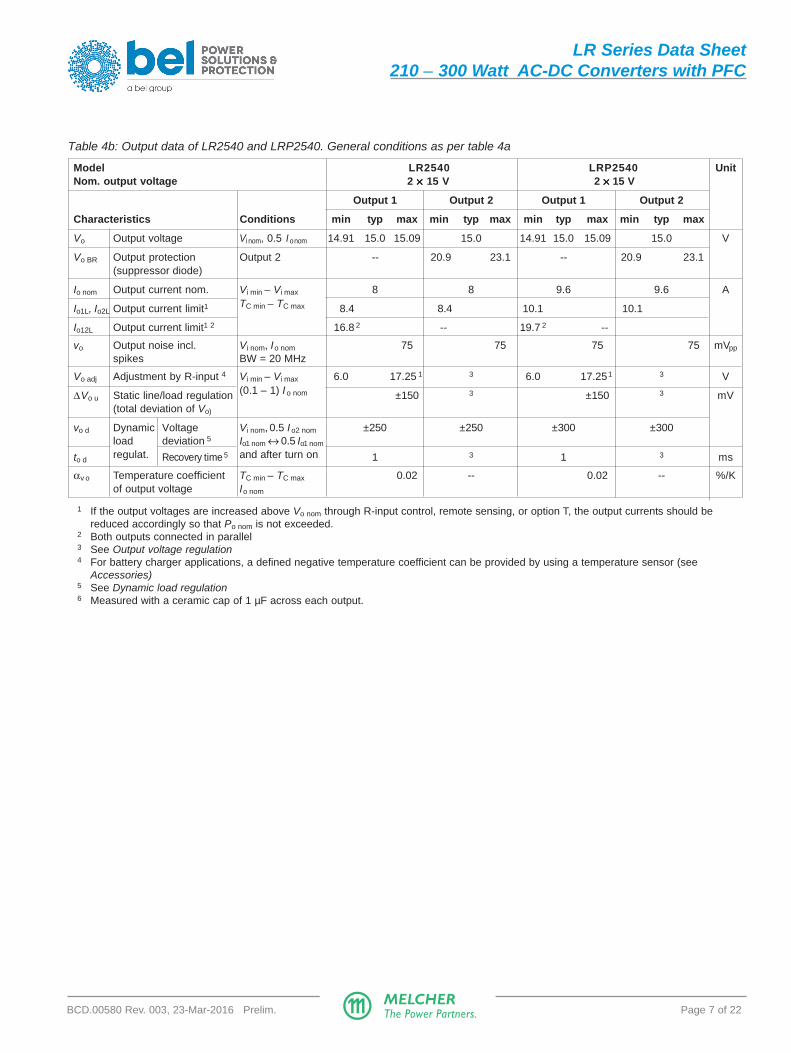
Table 4b: Output data of LR2540 and LRP2540. General conditions as per table 4a
Model LR2540 LRP2540 UnitNom. output voltage 2 ××××× 15 V 2 ××××× 15 V
Output 1 Output 2 Output 1 Output 2
Characteristics Conditions min typ max min typ max min typ max min typ max
Vo Output voltage Vi nom, 0.5 I o nom 14.91 15.0 15.09 15.0 14.91 15.0 15.09 15.0 V
Vo BR Output protection Output 2 -- 20.9 23.1 -- 20.9 23.1(suppressor diode)
Io nom Output current nom. Vi min – Vi max 8 8 9.6 9.6 A
Io1L, Io2L Output current limit1 TC min – TC max 8.4 8.4 10.1 10.1
Io12L Output current limit1 2 16.8 2 -- 19.7 2 --
vo Output noise incl. Vi nom, Io nom 75 75 75 75 mVpp
spikes BW = 20 MHz
Vo adj Adjustment by R-input 4 Vi min – Vi max 6.0 17.25 1 3 6.0 17.25 1 3 V
∆Vo u Static line/load regulation (0.1 – 1) Io nom ±150 3 ±150 3 mV(total deviation of Vo)
vo d Dynamic Voltage Vi nom, 0.5 Io2 nom ±250 ±250 ±300 ±300load deviation 5 Io1 nom ↔ 0.5 Io1 nom
to dregulat. Recovery time 5 and after turn on 1 3 1 3 ms
αv o Temperature coefficient TC min – TC max 0.02 -- 0.02 -- %/Kof output voltage Io nom
1 If the output voltages are increased above Vo nom through R-input control, remote sensing, or option T, the output currents should bereduced accordingly so that Po nom is not exceeded.
2 Both outputs connected in parallel3 See Output voltage regulation4 For battery charger applications, a defined negative temperature coefficient can be provided by using a temperature sensor (see
Accessories)5 See Dynamic load regulation6 Measured with a ceramic cap of 1 µF across each output.

BCD.00580 Rev. 003, 23-Mar-2016 Prelim. Page 8 of 22MELCHERThe Power Partners.
LR Series Data Sheet210 – 300 Watt AC-DC Converters with PFC
Table 4c: Output data of LR2880 and LRP2880. General conditions as per table 4a
Model LR2880 LRP2880 UnitNom. output voltage 2 ××××× 48 V 2 ××××× 48 V
Output 1 Output 2 Output 1 Output 2
Characteristics Conditions min typ max min typ max min typ max min typ max
Vo Output voltage Vi nom, 0.5 I o nom 47.7 48.0 48.3 48.0 47.7 48.0 48.3 48.0 V
Vo BR Output protection Output 2 -- 56.7 62.7 -- 56.7 62.7(suppressor diode)
Io nom Output current nom. Vi min – Vi max 2.2 2.2 2.6 2.6 A
Io1L, Io2L Output current limit1 TC min – TC max 2.3 2.3 2.65 2.65
Io12L Output current limit1 2 4.6 2 -- 5.3 2 --
vo Output noise incl. Vi nom, Io nom 240 240 240 240 mVpp
spikes BW = 20 MHz
Vo adj Adjustment by R-input 4 Vi min – Vi max 19.2 55.2 1 3 19.2 55.2 1 3 V
∆Vo u Static line/load regulation (0.1 – 1) Io nom ±0.5 3 ±0.5 3
(total deviation of Vo)
vo d Dynamic Voltage Vi nom, 0.5 Io2 nom ±0.8 ±0.8 ±1.0 ±1.0load deviation 5 Io1 nom ↔ 0.5 Io1 nom
to dregulat. Recovery time 5 and after turn on 1 3 1 3 ms
αv o Temperature coefficient TC min – TC max 0.02 -- 0.02 -- %/Kof output voltage Io nom
1 If the output voltages are increased above Vo nom through R-input control, remote sensing, or option T, the output currents should bereduced accordingly so that Po nom is not exceeded.
2 Both outputs connected in parallel3 See Output voltage regulation4 For battery charger applications, a defined negative temperature coefficient can be provided by using a temperature sensor (see
Accessories)5 See Dynamic load regulation6 Measured with a ceramic cap of 1 µF across each output.

BCD.00580 Rev. 003, 23-Mar-2016 Prelim. Page 9 of 22MELCHERThe Power Partners.
LR Series Data Sheet210 – 300 Watt AC-DC Converters with PFC
Thermal Considerations
If a converter is located in free, quasi-stationary air (convectioncooling) at the indicated maximum ambient temperature TA max
(see table Temperature specifications) and is operated withinthe specified input voltage range with nominal load, thetemperature measured at the Measuring point of casetemperature TC (see Mechanical Data) will approach theindicated value TC max after the warm-up phase. However, therelationship between TA and TC depends heavily upon theconditions of operation and integration into a system. Thethermal conditions are influenced by input voltage, outputcurrent, airflow, and temperature of surrounding componentsand surfaces. TA max is therefore, contrary to TC max, an in-dicative value only.
Caution: The installer must ensure that under all operatingconditions TC remains within the limits stated in the tableTemperature specifications.
Notes: Sufficient forced cooling or enhanced cooling with the helpof cooling plates (options B, B1) allows for TA higher than 71 °C(e.g. 85 °C), as long as TC max is not exceeded.
Thermal Protection
Two temperature sensors generate an internal inhibit signal,which disables the converter in the case of overtemperature.The outputs automatically recover when the temperature dropsbelow the limit.
Hold-up Time
The integrated storage capacitor (Cb) is loaded to the boostvoltage and ensures full output voltage with nominal loadduring the specified holdup time.
Output Protection
The 2nd output is protected by a suppressor diode againstovervoltage, which could occur due to a failure of the internalcontrol circuit. This suppressor diode was not designed towithstand externally applied overvoltages. Overload at any ofthe outputs will cause both outputs to shut-down.
Note: Vo BR of the suppressor diode is specified in ElectricalOutput Data. If this voltage is exceeded, the suppressor diodegenerates losses and may become a short circuit.
Note: The output voltage of the first output is monitored. If it ex-ceeds typ. 140% of Vo nom for 10 ms, the converter is inhibited bya latch. To reactivate, Vi must be removed or the converter dis-abled through an inhibit signal to pin 18.
Each output has its own current limiting circuit, providing arectangular output characterisitc and protecting against shortcircuit. There is no limitation for the capacitive load, and batterycharging is possible as well.
Series and Parallel Connection
Both outputs of the same converter can be series-connected orparallel-connected in order to double the output current or theoutput voltage respectively.
Outputs of different converters of the same model type may beseries-connected.
In parallel connection of several converters, the T-pins shouldbe interconnected so that all converters share the outputcurrent equally.
If both outputs of each converter are connected in series, Vo1–of both converters should be connected together. Interconnectthe T-pins as well; see fig. 3.
Notes:– Not more than 5 converters should be connected in parallel.
– If several outputs are connected in series, the resulting voltagemay exceed the SELV level.
– The R-pins should be left open-circuit. If not, the output voltagesmust individually be adjusted prior to paralleling within 1 to 2%, orthe R-pins should be interconnected.
– Series connection of second outputs without involving their mainoutputs should be avoided, as regulation may be poor.
Fig. 3Parallel connection of double-output models with their outputsconnected in series.T-pins and R-pins are referenced to Vo1–.
Load
Max. 5 converters
in parallel connection+ –
Power bus
Converter
#1
Vo2+
Vo1–
Vo2–
T
Converter
#2
Vo2–
Vo2+
T
JM195
10
22
4
6
14
14
12
Vo1+
4
6
R16
12
R16
10
T
8
Vo1+
Vo1–
Vo1–
Vo1–
8
Vo1+
Vo1+
22

BCD.00580 Rev. 003, 23-Mar-2016 Prelim. Page 10 of 22MELCHERThe Power Partners.
LR Series Data Sheet210 – 300 Watt AC-DC Converters with PFC
Fig. 6aModels LR2320 : Vo2 versus Io2 with various Io1
Fig. 4Output characteristic Vo versus Io (both outputs connected inparallel or in series)
Fig. 5Typical dynamic load regulation of Vo.
Vod
Vod
td td
Vo ±1% Vo ±1%
t
t
≥ 10 µs ≥ 10 µs
Vo
0
0.5
1
Io/Io nom
05102c
Output Voltage Regulation
If both outputs are connected in parallel or in series, theconverter exhibits a rectangular output characterisitic; see fig. 4.
The typ. dynamic load regulation illustrates fig. 5.
Output 1 is under normal conditions regulated to Vo nom,irrespective of the output currents.
However, Vo2 depends upon the load distribution; see fig. 6.The converters have incorporated switchable preloads and donot need a minimum load.
Note: If output 2 is not used, connect it in parallel with output 1!This ensures good regulation and efficiency.
Fig. 6bModels LR2880: Vo2 versus Io2 with various Io1
Vo
Vo nom
0.98
0.5
00.5 1.0
Io
IoL
Io
Io nom
05001a

BCD.00580 Rev. 003, 23-Mar-2016 Prelim. Page 11 of 22MELCHERThe Power Partners.
LR Series Data Sheet210 – 300 Watt AC-DC Converters with PFC
Auxiliary FunctionsInhibit for Remote On/Off
The outputs may be enabled or disabled by means of a logicsignal (TTL, CMOS, etc.) applied between the inhibit pin 18 (i)and pin 10 or 8 (Vo1–). In systems with several converters, thisfeature can be used to control the activation sequence of theconverters. If the inhibit function is not required, connect theinhibit pin 18 with pin 10 or 8 (Vo1–).
The inhibit disables the DC-DC converter immediately, witho utrespecting the hold-up time. The input section of the converteris not disabled.
Note: If pin 18 is not connected, the outputs are disabled.
Current Share Function
If the T-pins (22) of parallel-connected converters are linkedtogether, the converters share the output current evenly. Referto section Parallel and Series Connection.
VoRext1 ≈ 4 kΩ • ––––––––– Vo nom – Vo
or: between pin 16 (R) and pin 4 or 6 (Vo1+) to adjust theoutput voltage in the range of 100 – 110% of Vo nom.
(Vo – 2.5 V)Rext2 ≈ 4 kΩ • ––––––––––––––––––
2.5 V • (Vo/Vo nom – 1)
Caution: To prevent the converter from damage, the value of R 'ext
shall never be less than the value for increasing Vo1 to 110% !
Notes:– If the output voltages are increased above Vo nom via R-input
control, sense lines, or option T, the output currents should bereduced, so that Po nom is not exceeded.
– The second output of double-output models follows the voltageof the controlled main output.
Fig. 9Output voltage adjustment
Fig. 7Definition of Vinh and Iinh.
Fig. 8Output response as a function of inhibit control
Output Voltage Adjust
As a standard feature, the converters offer an adjustable outputvoltage. The control input R (pin 16) accepts either a controlvoltage Vext or a resistor Rext to adjust the output voltage. Wheninput R is not connected, the output voltage is set to Vo nom.
a) Adjustment by means of an external control voltage Vext
between pin 16 (R) and pin 10 or 8 (Vo1–):
The control voltage range is 1.0 – 2.75 V and allows for anadjustment in the range of approx. 40 – 110% of Vo nom.
Vo • 2.5 VVext ≈ –––––––– Vo nom
Caution: Applying an external control voltage >2.75 V maydamage the converter.
b) Adjustment by means of an external resistor:
Depending on the value of the required output voltage, theresistor shall be connected
either: between pin 16 (R) and pin 10 or 8 (Vo1–) to adjustthe output voltage in the range of approx. 40 – 100% of Vo nom.
R
Vo1+
Vo1–
+
Vext
–
4 kΩVref = 2.5 V
Rext1
Rext2
JM197
+
4
16
8
Input
Control
logic
0
0
i
1
0.1
1
Vo/Vo nom
ton
JM196
tf
tr
td
t
Table 5: Inhibit characteristics
Characteristic Conditions min typ max Unit
Vinh Inhibit Vo = on Vi min – Vi max – 10 0.8 Vvoltage Vo = off 2.4 50
I inh Inhibit current Vinh = 0 – 400 µA
t r Rise time 30 ms
t d Delay time
t f Fall time depending on Io
Vo1–
i
Vo1+
Iinh
Vinh
JM198
8
18
Input
6

BCD.00580 Rev. 003, 23-Mar-2016 Prelim. Page 12 of 22MELCHERThe Power Partners.
LR Series Data Sheet210 – 300 Watt AC-DC Converters with PFC
2.10
2.15
2.20
2.25
2.30
2.35
2.40
2.45Cell voltage [V]
–20 –10 0 10 20 30 40 50 °C
06139b
VC = 2.27 V, –3 mV/K VC = 2.27 V, –3.5 mV/KVC = 2.23 V, –3 mV/K VC = 2.23 V, –3.5 mV/K
Vo safe
Fig. 12Trickle charge voltage versus temperature for definedtemperature coefficient. Vo nom is the output voltage with openR-input.
Fig. 11Connection of a temperature sensor
Power
supplyLoad
–+
Input Vo–
R
Temperature sensor
ϑ
03099d
Battery
Vo+
+
Output Voltage Monitor
The output voltage monitor generates a logic "low" signal (NPNopen-collector output) at the D-output (pin 20), when Vo1 ≥0.96 Vo nom and ≤ 1.04 Vo nom (typ. values). Then, a green LED(Out OK) at the frontplate is illuminated. If the output voltage isadjusted by the R-input, the trigger levels are correctedaccordingly.
At low D-output, ID should be ≤ 50 mA. If the D-output is high(open collector), VD should be ≤ 50 V.
Note: Output overvoltage activates a latch; see Output Protection.
Fig. 10Output voltage monitor
Indicators
Two green indicators are visible at the front plate:
- Out OK; see Output Voltage Monitor
- In OK. This signal is activated, when Vi is in range and theconverter is not disabled by the inhibit signal.
Battery Charging /Temperature Sensor
All converters with an R-input are suitable for battery chargerapplication. For optimal battery charging and life expectancy ofthe battery an external temperature sensor can be connectedto the R-input. The sensor is mounted as close as possible tothe battery and adjusts the output voltage accoring to thebattery temperature.
Depending upon cell voltage and the temperature coefficient ofthe battery, different sensor types are available, seeAccessories.
Vo1+
Vo1–
DID
Rp
Input
JM199
Open
collector 20
6
10 Ω
4
VD

BCD.00580 Rev. 003, 23-Mar-2016 Prelim. Page 13 of 22MELCHERThe Power Partners.
LR Series Data Sheet210 – 300 Watt AC-DC Converters with PFC
Electromagnetic Compatibility (EMC)The LR Series has been successfully tested to the followingspecifications:
Electromagnetic Immunity
Table 6: Electromagnetic immunity (type tests)
Phenomenon Standard Level Coupling Value Waveform Source Test In Perf.mode 1 applied imped. procedure oper. crit.2
Electrostatic IEC / EN 4 5 contact discharge ±6000 Vp 1/50 ns 330 Ω 10 positive and yes Adischarge 61000-4-2 air discharge ±8000 Vp
10 negative(to case) discharges
Electromagnetic IEC / EN x6 antenna 20 V/m AM 80% /1 kHz n.a. 80 – 800 MHz yes Afield 61000-4-3 7 antenna 20 V/m AM 80% /1 kHz n.a. 800 – 1000 MHz yes A
10 V/m 1400 – 2000 MHz
5 V/m 2000 – 2700 MHz
3 V/m 5100 – 6000 MHz
3 antenna 10 V/m 50% duty cycle, n.a. 900 ±5 MHz yes A200 Hz rep. rate
Electrical fast IEC / EN 3 8 capacitive, o/c ±2000 Vp bursts of 5/50 ns 50 Ω 60 s positive yes Atransients/burst 61000-4-4 4 i /c, +i/–i ±4000 Vp
2.5/5 kHz over 60 s negative
direct 15 ms; burst transients perperiod: 300 ms coupling mode
Surges IEC / EN 3 9 i/c ±2000 Vp 1.2/50 µs 12 Ω 5 pos. and 5 neg. yes A61000-4-5 +i/– i ±1000 Vp 2 Ω surges per
coupling mode
Conducted IEC / EN 3 10 i, o, signal wires 10 VAC AM 80% 150 Ω 0.15 – 80 MHz yes Adisturbances 61000-4-6 (140 dBµV) 1 kHz
Power frequency IEC / EN 3 11 -- 100 A/m 60 s in all 3 axis yes Amagnetic field 61000-4-8
Pulsed IEC / EN - -- ±300 A/m 5 pulses per axis yes Bmagnetic field 61000-4-9 repetit. rate 10 s
1 i = input, o = output, c = case2 A = normal operation, no deviation from specs.; B = normal operation, temporary loss of function or deviation from specs possible5 Exceeds EN 50121-3-2:2015 table 6.3 and EN 50121-4:2006 table 1.4.6 Corresponds to EN 50121-3-2:2015 table 6.1 and exceeds EN 50121-4:2006 table 1.1.7 Corresponds to EN 50121-3-2:2015 table 6.2 and EN 50121-4:2006 table 1.2 (compliance with digital mobile phones).8 Corresponds to EN 50121-3-2:2015 table 5.2 and EN 50121-4:2006 table 2.2.9 Covers or exceeds EN 50121-3-2:2015 table 4.3 and EN 50121-4:2006 table 2.3.10 Corresponds to EN 50121-3-2:2015 table 5.1 and EN 50121-4:2006 table 3.1 (radio frequency common mode).11 Corresponds to EN 50121-4:2006 table 1.3.12 Corresponds to EN 50121-4:2006 table 1.5.

BCD.00580 Rev. 003, 23-Mar-2016 Prelim. Page 14 of 22MELCHERThe Power Partners.
LR Series Data Sheet210 – 300 Watt AC-DC Converters with PFC
Fig. 15aTyp. conducted emissions (peak/quasipeak and average) atthe input according to EN 55011/22, measured at Vi = 230 Vand Io nom (LR2320-9G).
Fig. 16aTyp. radiated emissions accord. to EN 55011/22, antenna 10 mdistance, measured at Vi = 230 V and Io nom (LR2880-9G).
Fig. 16bTyp. radiated emissions accord. to EN 55011/22, antenna 10 mdistance, measured at Vi = 230 V and Io nom (LR2880-9G).
Fig. 15bTyp. conducted emissions (peak/quasipeak and average) atthe input according to EN 55011/22, measured at Vi = 230 Vand Io nom (LR2320-9G).
Electromagnetic Emissions
All models comply with Class A according to EN 55011/55022for conducted and radiated emissions.

BCD.00580 Rev. 003, 23-Mar-2016 Prelim. Page 15 of 22MELCHERThe Power Partners.
LR Series Data Sheet210 – 300 Watt AC-DC Converters with PFC
Immunity to Environmental Conditions
Table 8: Mechanical and climatic stress (type tests)
Test method Standard Test conditions Status
Cab Damp heat IEC/EN 60068-2-78 Temperature: 40 ±2 °C Convertersteady state MIL-STD-810D section 507.2 Relative humidity: 93 +2/-3 % not
Duration: 56 days operating
Db Damp heat test, EN 50155:2007, clause 12.2.5 Temperature: 55 °C and 25 °C Convertercyclic IEC/EN 60068-2-30 Cycles (respiration effect): 2 not
Duration: 2× 24 h operating
Bd Dry heat test EN 50155:2007, clause 12.2.4 Temperature: 70 °C Convertersteady state IEC/EN 60068-2-2 Duration: 6 h operating
Ad Cooling test EN 50155:2007, clause 12.2.3 Temperature, duration –40 °C, 2 h Conv. notsteady state IEC/EN 60068-2-1 Performance test +25 °C operating
-- Salt mist test EN 50155:2007, clause 12.2.10 Temperature: 35 ±2 °C Convertersodium chloride class ST3 Duration: 48 h not(NaCl) solution operating
Fc Vibration IEC/EN 60068-2-6 Acceleration amplitude: 0.35 mm (10 – 60 Hz) Converter(sinusoidal) MIL-STD-810D section 514.3 5 gn = 49 m/s2 (60 - 2000 Hz) operating
Frequency (1 Oct/min): 10 – 2000 HzTest duration: 7.5 h (2.5 h in each axis)
Fh Random vibration IEC/EN 60068-2-64 Acceleration spectral density: 0.05 gn2/Hz Converter
broad band Frequency band: 8 – 500 Hz operating(digital control) and Acceleration magnitude: 4.9 gn rms
guidance Test duration: 1.5 h (0.5 h in each axis)
E b Bump IEC/EN 60068-2-29 Acceleration amplitude: 25 gn = 245 m/s2 Converter(half-sinusoidal) MIL-STD-810D section 516.3 Bump duration: 6 ms operating
Number of bumps: 6000 (1000 in each direction)
E a Shock IEC/EN 60068-2-27 Acceleration amplitude: 50 gn = 490 m/s2 Converter(half-sinusoidal) MIL-STD-810D section 516.3 Bump duration: 11 ms operating
Number of bumps: 18 (3 in each direction)
-- Shock EN 50155:2007 clause 12.2.11, Acceleration amplitude: 5.1 gn ConverterEN 61373 sect. 10, Bump duration: 30 ms operatingclass B, body mounted 1 Number of bumps: 18 (3 in each direction)
-- Simulated long life EN 50155:2007 clause 12.2.11, Acceleration spectral density: 0.02 gn2 / Hz Converter
testing at EN 61373 sect. 8 and 9, Frequency band: 5 – 150 Hz operatingincreased random class B, body mounted 1 Acceleration magnitude: 0.8 gn rms
vibration levels Test duration: 15 h (5 h in each axis)
1 Body mounted = chassis of a railway coach
Temperatures
Table 8: Temperature specifications, valid for an air pressure of 800 - 1200 hPa (800 - 1200 mbar)
Temperature -9 Unit
Characteristics Conditions min typ max
TA Ambient temperature Converter operating –40 711 °C
TC Case temperature –40 951 2
TS Storage temperature Non operational –55 85
1 See Thermal Considerations.2 Overtemperature lockout at TC >95 °C (An NTC resistor on primary and secondary heatsink).

BCD.00580 Rev. 003, 23-Mar-2016 Prelim. Page 16 of 22MELCHERThe Power Partners.
LR Series Data Sheet210 – 300 Watt AC-DC Converters with PFC
111 (
3U
)
168.5
60
51.5
26.4
3.27
7 TE 5 TE
Out OK
25.9
Front plate Main face Back plate
(171.0 to 171.9)
50
11.8
152
100
M4
55
81528
Measuring point ofcase temperature TC
d
Screw holes of the
frontplate
∅5 x 90°
∅2.8 0.2
In OK
11.3
30.3
552
27.38
JM092
Notes:
– d ≥ 15 mm, recommended minimum distance tonext part in order to ensure proper air circulationat full output power.
– free air location: the converter should be mountedwith fins in a vertical position to achieve maximumairflow through the heat sink.
Fig. 17Aluminum case of LR models with heat sink;black finish (EP powder coated);weight approx. 1.5 kg
EuropeanProjection
Mechanical DataDimensions in mm. The converters are designed to be inserted intoa 19" rack, 160 mm long, according to IEC 60297-3.
Reliability
Table 9: MTBF and device hours
Ratings at specified Model MTBF Demonstrated hourscase temperaturebetween failures 1
Accord. to IEC 62380 LR2320-9RG
1 Statistical values, based upon an average of 4300 working hours per year and in general field use over 5 years; upgrades and customer-induced errors are excluded.

BCD.00580 Rev. 003, 23-Mar-2016 Prelim. Page 17 of 22MELCHERThe Power Partners.
LR Series Data Sheet210 – 300 Watt AC-DC Converters with PFC
Notes:
– d ≥ 15 mm, recommended minimum distance tonext part in order to ensure proper air circulationat full output power.
– free air location: the converter should be mountedwith fins in a vertical position to achieve maximumairflow through the heat sink.
Fig. 18Aluminum case of LRP models with heat sink;black finish (EP powder coated);weight approx. 1.8 kg
EuropeanProjection
Dimensions in mm. The converters are designed to be insertedinto a 19" rack, 160 mm long, according to IEC 60297-3.
159 4.5
89
11
1 (
3U
)
168.5
d
80
6.5 5
1.5
3.27
7 TE 9 TE
25
.91
1.8
Front plate Main face Back plate
(171.0 .... 171.9)
JM093
Mounting slots for chassis or wall mounting
Screw holes of the
frontplate
∅5 x 90°
∅2.8 0.2
27.38
Out OKIn OK
26
.4
11
.3
552
30.3
Measuring point ofcase temperature TC

BCD.00580 Rev. 003, 23-Mar-2016 Prelim. Page 18 of 22MELCHERThe Power Partners.
LR Series Data Sheet210 – 300 Watt AC-DC Converters with PFC
6.5
11
.21
3
14
0
17.3 133.4 ±0.230
168
5 47.2
38.5
12
76
.5
11.8
11027
Fig. 19Option B: Aluminum case S with large cooling plate; black finish (EP powder coated).Suitable for front mounting.Total weight approx. 1.5 kg
Note: Long case with option B2, elongated by 60 mm for 220 mmrack depth, is available on request. (No LEDs)
EuropeanProjection
Fig. 20Option B1: Aluminum case S with small cooling plate; black finish (EP powder coated).Suitable for mounting with access from the backside.Total weight approx. 1.4 kg.
11
1 (
3U
)
17.3 133.4
168
10
1
547.2
1585
M 4
5
Measuring point ofcase temperature TC
50
(171.0 ... 171.9)
3.27
7 TE 4 TE
JM094
38.5
11.8
Out OK
In OK

BCD.00580 Rev. 003, 23-Mar-2016 Prelim. Page 19 of 22MELCHERThe Power Partners.
LR Series Data Sheet210 – 300 Watt AC-DC Converters with PFC
Fig. 21View of module's male connector
Safety and Installation Instructions
Connector Pin Allocation
The connector pin allocation table defines the electricalpotentials and the physical pin positions on the H15 connector.The protective earth is connected by a leading pin (no. 24),ensuring that it makes contact with the female connector first.
Installation Instructions
The converters are components, intended exclusively forinclusion within other equipment by an industrial assemblyoperation or by professional installers. Installation must strictlyfollow the national safety regulations in compliance with theenclosure, mounting, creepage, clearance, casualty, markings,and segregation requirements of the end-use application.
Connection to the system shall be made via the femaleconnector H15; see Accessories. Other installation methodsmay not meet the safety requirements.
Pin no. 24 ( ) is connected with the case. For safety reasons itis essential to connect this pin reliably to protective earth.
Notes:
– Pin 18 (inhibit) must be connected to pin 14 (Vo1) to enable theconverter.
– Do not open the converter, or warranty will be invalidated.
S10002b
32 28 24 20 16 12 8 4
30 26 22 18 14 10 6
Fixtures for retention clips
– If the second output is not used, connect it parallel with the mainoutput.
Make sure that there is sufficient airflow available forconvection cooling and verifiy it by measuring the casetemperature TC, when the converter is installed and operatedin the end-use application; see Thermal Considerations.
Ensure that a converter failure (e.g. an internal short-circuit)does not result in a hazardous condition.
Standards and Approvals
The converters are safety-approved to UL/CSA 60950-1 2nd
Ed. and IEC/EN 60950-1 2 nd Ed.
The converters correspond to Class I equipment (caseconnected to ground). They have been evaluated for:
• Building-in
• Basic insulation between input and case based on 250 VA;basic insulation between outputs and case; double orreinforced insulation between input and outputs
• Functional insulation between outputs
• Overvoltage category II
• Pollution degree 2 environment
• Max. altitude: 2000 m
• The converters fulfill the requirements of a fire enclosure.
The output voltage is considered as SELV, except LR/LRP2880 with series-connected outputs.
The converters are subject to manufacturing surveillancein accordance with the above mentioned standards and ISO9001:2008. CB-scheme is available on request.
Railway Application and Fire Protection
The converters have been designed by observing the railwaystandards EN 50155 and EN 50121-4. All boards are coatedwith a protective lacquer.
The converters comply with NF-F16 (I2/F1). They also complywith EN 45545-1, EN 45545-2 (2013), if installed in a technicalcompartment or cabinet.
Protection Degree and Cleaning Liquids
In order to avoid possible damage, any penetration of cleaningfluids has to be prevented, since the power supplies are nothermetically sealed.
The protection degree is IP 40, provided that the femaleconnector is fitted to the converter.
Isolation and Protective Earth
The electric strength test is performed in the factory as routinetest according to EN 50514 and IEC/EN 60950 and should notbe repeated in the field. The company will not honor anywarranty claims resulting from incorrectly executed electricstrength field tests. The resistance case to the earth pin (<0.1Ω) is tested as well.
Table 10: Pin allocation
Pin no. Name Function
4 Vo1+ Pos. output 2
6 Vo1+ Pos. output 2
8 Vo1– Neg. output 2
10 Vo1– Neg. output 2
12 Vo2+ Pos. output 1
14 Vo2– Neg. output 1
16 R Output voltage adjust
18 i Inhibit
20 D Out OK
22 T Current share
24 1 Protection earth PE and case
26 + 28 N∼ Neutral line
30 + 32 L∼ Phase line
1 Leading pin (pre-connecting)

BCD.00580 Rev. 003, 23-Mar-2016 Prelim. Page 20 of 22MELCHERThe Power Partners.
LR Series Data Sheet210 – 300 Watt AC-DC Converters with PFC
Description of Options
F0, F2 Fuse Options
The converters exhibit 1 fuse in the phase line.
Option F0 is required for full compliance with EN 50155 (nofuse allowed).
Option F2 is required for several countries, but especially if theconverter is operated between phases or if the neutral linecannot be allocated (e.g., for German Schuko connectors).
B, B1 Cooling Plates
Where a cooling surface is available, we recommend the useof a cooling plate instead of the standard heat sink. Themounting system should ensure that the maximum casetemperature TC max is not exceeded. The cooling capacity iscalculated by (η see Model Selection):
(100% – η)PLoss = –––––––––– • Vo • Ioη
For the dimensions of the cooling plates; see Mechanical Data.
Table 11: Isolation
Characteristic Input to case Outputs to case Output 1 to Alarm signals Unitand outputs and input output 2 to everything
Electric Factory test 1 to 4 s 2.84 1 4.3 0.5 4.3 kVDCstrength AC test voltage equivalent 2.0 1 3.0 0.3 3.0 kVACtest to factory test
Insulation resistance at 500 VDC >300 >300 >300 -- MΩCreepage distances ≥ 3.2 2 ≥ 4.5 -- -- mm
1 According to EN 50116 and IEC/EN 60950, subassemblies connecting input to output are pre-tested with 5.6 kVDC or 4 kVAC.2 Input to outputs: 6.4 mm

BCD.00580 Rev. 003, 23-Mar-2016 Prelim. Page 21 of 22MELCHERThe Power Partners.
LR Series Data Sheet210 – 300 Watt AC-DC Converters with PFC
AccessoriesA variety of electrical and mechanical accessories areavailable including:
– Front panels for 19" DIN-rack: Schroff or Intermas, 12or 16TE /3U; see fig. 25.
– Mating H15 connectors with screw, solder, faston, or press-fit terminals.
– Coding clips for connector coding HZZ00202
– Pair of connector retention clips HZZ01209-G
– Connector retention brackets HZZ01216-G (CRB-HKMS)
– Cable hood for H15 connectors:
- HZZ00141-G, screw version- HZZ00142-G, use with retention brackets HZZ01218-G- HZZ00143-G, metallic version providing fire protection
– Cage clamp adapter HZZ00144-G; see fig. 28.
– DIN-rail mounting assembly HZZ0615-G (DMB-K/S)
– Wall-mounting plate K02 (HZZ01213-G) for models withoption B1
– Additional external input and output filters
– Different battery sensors S-KSMH... for using the converteras a battery charger. Different cell characteristics can beselected; see fig. 32, table 12, and Battery Charging /Temperature Sensors.
For additional accessory product information, see theaccessory data sheets listed with each product series orindividual model at our web site:
www.belpowersolutions.com/power
Fig. 23Connector retention brackets HZZ01216-G (CRB-HKMS)
20 to 30 Ncm
Fig. 24Connector retention clips to fasten the H15 connector tothe rear plate; see fig. 24. HZZ01209-G consists of 2 clips.
Fig. 25Cage clamp adapter HZZ00144-G
Fig. 22Different front panels

BCD.00580 Rev. 003, 23-Mar-2016 Prelim. Page 22 of 22MELCHERThe Power Partners.
LR Series Data Sheet210 – 300 Watt AC-DC Converters with PFC
Fig. 30Chassis- or wall-mounting plateHZZ01213-G (Mounting plate K02)
56 (2.2")L
L = 2 m (standard length) other cable lengths on request
adhesive tape
26 (1.02")
9.8
(0.4
")09125a
Fig. 31DIN-rail mounting assembly HZZ00615-G (DMB-K/S)
Fig 29Different cable hoods
EuropeanProjection
Table 12: Battery temperature sensors
Battery Sensor Cell Cell temp. Cablevoltage type voltage coefficient lengthnom. [V] [V] [mV/K] [m]
12 S-KSMH12-2.27-30-2 2.27 –3.0 2
12 S-KSMH12-2.27-35-2 2.27 –3.5 2
24 S-KSMH24-2.27-30-2 2.27 –3.0 2
24 S-KSMH24-2.27-35-2 2.27 –3.5 2
24 S-KSMH24-2.31-35-0 2.31 –3.5 4.5
24 S-KSMH24-2.31-35-2 2.31 –3.5 2
24 S-KSMH24-2.35-35-2 2.35 –3.5 2
48 S-KSMH48-2.27-30-2 2.27 –3.0 2
48 S-KSMH48-2-27-35-2 2.27 –3.5 2
Fig. 32Battery temperature sensor
Note: Other temperature coefficients and cable lengths areavailable on request.
NUCLEAR AND MEDICAL APPLICATIONS - These products are not designed or intended for use as critical components in life support systems,equipment used in hazardous environments, or nuclear control systems.
TECHNICAL REVISIONS - The appearance of products, including safety agency certifications pictured on labels, may change depending on thedate manufactured. Specifications are subject to change without notice.
Copyright © 2016, Bel Power Solutions Inc. All rights reserved. www.belpowersolutions.com