hpg range - rotork...12.5 limit switch setting 14 12.6 flow regulator setting 15 12.7 pipeline gas...
TRANSCRIPT

HPG RangeDirect High Pressure Gas Valve Actuator
Installation, Commissioning and Maintenance Manual
A4US
US
A4
US A4
US
A4
A4 US
US
A4
US
A4
A4 US

Installation, Commissioning and Maintenance Manual2
Section Page Section Page
Contents
THIS MANUAL CONTAINS IMPORTANT SAFETY INFORMATION. PLEASE ENSURE IT IS THROUGHLY READ AND UNSDERSTOOD BEFORE INSTALLING, OPERATING OR MAINTAINING THE EQUIPMENT.
ROTORK RESERVES THE RIGHT TO MODIFY, AMEND AND IMPROVE THIS MANUAL WITHOUT NOTICE.
ROTORK IS NOT RESPONSIBLE FOR DAMAGE OR INJURY CAUSED BY THE FAILURE TO OBSERVE THE INSTRUCTIONS CONTAINED HEREIN.
1. Introduction 3
1.1 Customer Service 3
2. Standards and Regulations 3
3. General Information 4
3.1 Appropriate Usage 4
4. Health and Safety 4
4.1 Residual Risks 4
4.2 Thermal Risks 4
4.3 Health Risks 4
4.4 Mechanical Risks 4
4.5 Noise 4
5. Labels and Nameplates 5
5.1 Labels and Nameplates 5
6. Operating Limits 6
6.1 Temperature 6
6.2 Allowed Fluid Types 6
6.3 Expected Lifetime 6
6.4 Tightening Torque Chart 6
7. Handling and Lifting 7
7.1 Lifting Recommendations 7
7.2 Lifting Instructions 7
8. Storage 8
9. Long Term Storage 8
10. Installation on Valve 9
10.1 Preliminary Actions 9
10.2 Instructions 9
11. Removal from Valve 10
12. Operation 11
12.1 Description 11
12.2 Operating Description 12
12.3 Angular Stroke Setting 12
12.4 Hand Pump Override 14
12.5 Limit Switch Setting 14
12.6 Flow Regulator Setting 15
12.7 Pipeline Gas Power Supply 15
12.8 Connection to Pipeline 15
12.9 Electrical Connections 16
12.10 Start Up 16
12.11 Circuit Gas Venting 17
13. Dismantling and Disposal 18
14. Rotork Sales and Service 18
15. Troubleshooting 19
16. Periodic Maintenance 21
17. Part List 32
18. Grease and Hydraulic Oil Specification 32
18.1 Grease 32
18.2 Hydraulic Oil 33
A4US
US
A4
US A4
US
A4
A4 US
US
A4
US
A4
A4 US

3
This manual covers the High Pressure Gas (HPG) (type 2) Actuator range.
In this manual, warning indications are represented by icons, according to ISO 7010 Safety Signs:
Generic Danger
Hand Crush / Pinch Point
Electrocution
Explosive Material
Substances toxic for the environment (terrestrial or aquatic) or which could have harmful, long-term effects
1.1 Customer Service
For technical assistance, please contact Rotork customer service:
E-mail: [email protected]
Rotork, Via Padre Jacques Hamel, 138B, Porcari, Lucca, 55016, IT. Tel: +39 0583-222-1
Rotork plc, Brassmill Lane, Bath, UK. Tel +44 (0)1225 733200
Actuators destined for European member states have been designed, built and tested according to the Quality Control System, in compliance with the EN ISO 9001:2008 standard and with the following regulations/directive.
• 2006/42/EC: Machinery Directive
• 2014/68/EU: Pressure Equipment Directive (PED)
• 2014/34/EU: Directive For Safety Equipment And Systems to be used in potentially explosive atmospheres (ATEX)
• 2014/30/EU: Electromagnetic Compatibility Directive
• EN ISO 12100: Machinery Safety Directive
• EN 60079-14: Explosive Atmospheres - Part 14: Electrical Installations Design, Selection And Erection
• ISO 80079-36: Non-Electrical Equipment For Explosive Atmospheres - Basic method and requirements
• EN 1127–1: Explosive Atmospheres – Explosion prevention and protection
• ISO 80079-37: Non-Electrical Equipment For Explosive Atmospheres - Non-electrical type of protection construction safety "c", control of ignition sources "b", liquid immersion "k"
• EN 60079-14:2014: Explosive Atmospheres. Electric installations design, selection and erection
• EN ISO 7010: Safety Signal
2. Standards and Regulations1. Introduction
A4US
US
A4
US A4
US
A4
A4 US
US
A4
US
A4
A4 US

Installation, Commissioning and Maintenance Manual4
This manual is produced to enable a competent user to install, operate, adjust, inspect, maintain, dismantle and dispose Rotork HPG Range actuators.
The mechanical installation should be carried out as outlined in this manual and also in accordance with any relevant national standard codes of practice.
Maintenance and operation should be carried out in accordance with the National Legislation and Statutory Provisions relating to the safe use of this equipment, applicable to the site of installation.
Any inspection or repair in a Hazardous Area should not be undertaken unless it conforms to National Legislation and Statutory Provisions relating to the specific Hazardous Area.
Only Rotork approved replacement parts should be used. Under no circumstances should any modification or alteration be carried out on the equipment, as this could invalidate the conditions under which its certification was granted.
Only trained and experienced operators should be allowed to install, maintain and repair Rotork actuators. Work undertaken must be carried out in accordance with instructions in this manual. The user and those persons working on this equipment should be familiar with their responsibilities under any statutory provisions relating to the Health and Safety of their workplace.
Operators should always wear appropriate personal protection devices (PPDs) in line with the existing plant regulations.
3.1 Appropriate Usage
Rotork HPG actuators have been specifically developed to motorize 1/4” turn valves such as ball valves, butterfly valves or plug valves, installed on pipelines for gas transport and distribution.
Improper use can damage the equipment or cause dangerous situations for health and safety. Rotork declines any responsibility for damage to people and/or objects resulting from the use of the equipment for applications different from those described in the present manual.
Before installing the equipment, verify it is suitable for the intended application. If unsure consult Rotork.
4.1 Residual Risks
Residual risks resulting from equipment risk evaluation performed by Rotork.
4.2 Thermal Risks
Risk Hot / cold surfaces during normal operation (RES_01).
Preventive measures Operators should wear protective gloves.
4.3 Health Risks
Risk Pressurized fluid ejection during normal operation (RES_02).
Preventive measures All fittings must be properly sealed. All fixing clamps must be correctly tightened and sealed.
Risk Risk of intoxication (according to the type of medium utilized) (RES_06).
Preventive measures Operators must use P.P.D.s and any other equipment (breathing apparatus) based on the type of supply medium.
4.4 Mechanical Risks
Risk Uncontrolled movement (remote operation) (RES_03).
Preventive measures Assure that the actuator can not be operated remotely. Prior to starting, remove pneumatic supply, vent all pressure vessels, and remove electrical power.
Risk Presence of moving parts (center body, in the valve adapter) (RES_04).
Preventive measures Check center body cover is installed and hex bolts tightened before start-up.
4.5 Noise
Risk Noise >85 dB during operation (RES_05).
Preventive measures Operators should wear ear protections. Operators should not stand near the
equipment during operation.
3. General Information 4. Health and Safety
A4US
US
A4
US A4
US
A4

5
5.1 Labels and Nameplates
For actuators destined for site within the European Union, the CE mark certifies the conformity of the machine with the essential health and safety requirements of the European Directives for the product.
The plate is applied externally on the center body cover and displays, the following data:
• Serial number
• Tag number
• Model
• Min/max operating pressure
• Order number
• Month / year of manufacture
• ATEX protection
• CE conformity marking
• Name of technical file deposited with a Notified Body
Fig 5.1 CE nameplate
If CE (PED) marking is required, the following plate applies:
• Serial number
• Cylinder code
• 2014/68/EU category
• Fluid
• Volume (Lt.)
• Production month and year
• Maximum working pressure
• Design pressure
• Testing pressure
• Minimum / Maximum design temperature
• CE conformity marking
• Notified body number 1370
Fig 5.2 PED nameplate
Do not remove or modify the nameplate/s. Nameplate must be kept legible at all times.
In case the plate is damaged or illegible, a duplicate must be requested.
5. Labels and Nameplates
A4 US
US
A4
US
A4
A4 US

Installation, Commissioning and Maintenance Manual6
Do not use the actuator for applications outside its operating limits. Verify operating limits on the nameplate.
6.1 Temperature
Standard: -29 to +60 °C (-20 to +140 °F) Low: -46 to +40 °C (-51 to +104 °F)
Prevent external surface temperature to reach the ignition point in potentially explosive environments.
The actuator surface temperature is strictly dependent on the temperature of the process fluid used and by the irradiation’s conditions. The end user has to check the surface temperature of the assembly, so that this cannot go over the minimum gas ignition’s temperature, which classifies the area with the explosion’s risk.
Dust and debris accumulated on the actuator will slow down its cooling and contribute to the increase of its external temperature.
6.2 Allowed Fluid Types
Inert Gas, Sweet Dry natural Gas.
6.3 Expected Lifetime
Expected Lifetime greater than 25 years, in normal service conditions and with planned maintenance.
6.4 Tightening Torque Chart
RECOMMENDED TIGHTENING TORQUE
(Class 8.8 bolts)
Bolt Size Nm Ft. Lbs
M6 8.5 6
M8 20 15
M10 40 30
M12 55 40
M14 110 81
M16 220 162
M20 430 317
M22 425 313
M24 585 431
M27 785 579
M30 1250 921
M33 1400 1030
M36 1750 1290
6. Operating Limits
A4US
US
A4
US A4
US
A4

7
Only trained and experienced personnel should handle/lift the actuator.
The actuator is supplied packed on pallets suitable for normal handling.
Handle the actuator with care. Never stack pallets.
7.1 Lifting Recommendations
• The lifting device and the sling must be suitably rated for the actuator weight and dimensions
• Do not use damaged sling(s)
• The sling must not be shortened with knots or bolts or any other makeshift device
• For lifting purposes, use only suitable lifting tools.
• Do not drill holes, weld eye bolts or add any other type of lifting device on the actuator external surface
• Do not lift the actuator and valve combination with the actuator lifting lugs, only lift the actuator/valve assembly using the valve lifting lugs
• Every assembly must be estimated separately for a safe and correct lifting
• Avoid pulls or abrupt movements during lifting and avoid pushing the load
• During lifting operations, do not handle the slings and/or the actuator
7.2 Lifting Instructions
NOTE: Indication of weight, center of gravity, lifting points are reported within specific project documentation.
Consult project specific documentation before lifting.
• Prior to lifting the actuator, remove electrical power and vent all pressure vessels
• Place the textile eye slings as shown in Fig 7.1
• Hook an additional chain sling on the gas/oil tanks support lifting plate
The actuator must remain horizontal; balance the load.
• If the actuator is equipped with a backup or reference tank, hook a chain on the additional lifting lug on the rear bracket
• Angle β must between 0° and 45° as shown in Fig 7.2
Fig 7.1 Lifting
Directionof Pull
Fig 7.2 Lifting angle
7. Handling and Lifting
A4 US
US
A4
US
A4
A4 US

Installation, Commissioning and Maintenance Manual8
Rotork actuators are fully tested before leaving the factory.
In order to keep actuator in good condition until installation, at least the following measures are recommended:
• Check presence and assembling of dust plugs
• Keep the actuator on shipping pallet until installation
Never put the actuator directly on the ground.
• Protect the valve coupling area (adapter flange and coupling joint, etc.) with rust preventive oil e.g. Mobilarma LT or equivalent
• Protect against weather action, covering the actuators with appropriate polyethylene sheets
• Check the actuator condition every 6 months and verify the above protection measures remain in place
Remove package only at the installation time.
Actuator vent ports must be protected with polyethylene sheet to prevent water ingress during storage.
If long term storage is necessary, further operations must be carried out to maintain the actuator in a good working condition:
• Replace the plastic plugs with metal plugs
• Stroke the actuator every 12-months:
• Cycle the actuator (using nitrogen gas with purity level >99,999%) to the working pressure indicated on the name plate
• Cycle the actuator with all the existing controls (i.e. two complete strokes - one open, one closed) at least 5 times
• Cycle the actuator fitted with the hydraulic manual override by means of the hand pumps for 4 complete strokes
• Disconnect the pipeline gas and electric (if present) supply from the actuator, and carefully close all the threaded connections of the actuator
• Remove electrical components covers (if present) to ensure control terminals are clean and free from oxidation and humidity. Reassemble the covers
• In case of storage for over 12 months prior to installation, it is recommended to operate the actuator to verify correct operation
8. Storage 9. Long Term Storage
A4US
US
A4
US A4
US
A4

9
Before proceeding, read and understand the Health and Safety information.
NOTE: The valve should be properly secured prior to perform following operations according to instructions provided by the Valve’s Manufacturer.
Prior to performing any operations check the operating drawings and TAG numbers. Consult Rotork for any additional information.
10.1 Preliminary Actions
Verify the ATEX classification of the actuator is compatible with the plant zoning. Refer to actuator nameplate.
• The centerline of the cylinder is usually aligned to the centerline of the associated pipe work
• Ensure all fasteners are adequately tightened, to avoid loosening during operation, taking into account the vibrations induced by the dynamics of the pipeline
• Piping used to provide pipeline gas power to the actuator must be free from contaminants and debris. Ensure tubing runs are adequately fastened and supported to minimize repetitive stress induced the dynamics of the pipeline
• Ensure there are no leaks from any pipeline gas connections. Tighten as required
10.2 Instructions
The assembling can be performed by:
• Mounting directly using the actuator housing flange with threaded holes
• Using an adapter and a coupling joint between the actuator and the valve
The assembly position of the actuator must be in accordance with the actuator design, plant requirements and the valve model.
In order to assemble the actuator onto the valve, proceed as follows:
• Verify the coupling dimensions of the valve flange and stem; they must meet the actuator coupling dimensions
• Set the valve in the closed position. The actuator is supplied in the closed position. Check the position of the actuator by means of the position indicator on the center body or on the limit switch (if present)
• Clean the coupling flange of the valve and remove anything that might prevent adherence to the actuator flange. Grease shall be completely removed
• Lubricate the valve stem with oil or grease, to facilitate assembling
• Lift the actuator according to Handling and Lifting instructions (section 7)
• If possible, place the valve stem in a vertical position to facilitate assembling - in this case the actuator must be lifted while the coupling flange is kept in the horizontal position
• If the assembly is done using an adapter and a coupling joint, assemble the coupling joint onto the valve stem before proceeding with the assembly of the actuator
• Do not exert any force while lowering the actuator onto the valve
Installation must be performed by qualified personnel.
Hands must be kept away from the coupling area.
• Fix the actuator to the valve by means of threaded connections (bolts, stud bolts and nuts)
• Tighten the bolts or the nuts of the connecting stud bolts to the correct torque, in accordance with the size and material characteristics of the bolts installed by the customer
Support the actuator until full installed and fixing bolts are correctly tightened.
Attention: Do not pressurize the actuator/valve adpapter.
• Check for possible damage to the paint-work and repair if necessary, according to painting specification
Fig 10.1 Actuator/valve assembling example
10. Installation on Valve
A4 US
US
A4
US
A4
A4 US

Installation, Commissioning and Maintenance Manual10
The end user is in charge of removing the actuator from the valve.
Removal shall be performed only by qualified staff, wearing/using appropriate personal protection devices.
Do not remove the actuator if the valve is blocked in the intermediate position. Contact Rotork customer service.
In order to disassemble the actuator from the valve, proceed as follows:
• Cut off the gas and electrical power supply
• Vent any storage tanks (if present)
• Remove the gas supply pipe from the actuator
• Release any pressure from the control group
• Vent the gas circuit according to instructions in Circuit Gas Venting (section 12.11)
• Remove control and signal lines from electrical components
• Sling the actuator according to Handling and Lifting instructions (section 7)
• Unscrew bolts or nuts from the stud bolts fixing the actuator to the valve
• Lift and remove the actuator from the valve
11. Removal from Valve
A4US
US
A4
US A4
US
A4

11
The following instructions must be followed and integrated into end user safety program when installing and using Rotork products. Read and save all instructions prior to installing, operating and servicing this product.
Follow all warnings, cautions and instructions marked on and supplied with the product.
Install equipment as specified in Rotork installation instructions and as per applicable local and national codes of practice. Connect all products to the proper pipeline gas sources.
When replacement parts are required, ensure that the qualified service technician uses only replacement parts specified by Rotork.
Substitutions will invalidate any hazardous area certification and may result in fire, electrical shock, other hazards or improper operation.
12.1 Description
The HPG series actuator is a high pressure-double acting actuator specifically designed to use pipeline gas as the motive power source.
The main components of a HPG actuator are shown in Figure 12.1, 12.2 and 12.3.
IT DESCRIPTION QTY
1A1.1 Mechanical End Stopper 2
1A1.2 Center body 1
1A1.3 Hydraulic cylinder 1
1A1.4 High pressure pneumatic cylinder
1
1P1 Hydraulic Override Pump 1
C1 Gas Block 1
1S1 Limit switch box 1
1V50A Solenoid valves (OPEN) 1
1V50B Solenoid valves (CLOSE) 1
Table 1: HPG Parts list
Main components of a direct gas actuator are:
• High pressure pneumatic actuator
• Hydraulic cylinder equipped with manual pump
• Limit switch box
• Gas block
Use only control devices supplied by Rotork.
See further paragraphs for main functions description and main components for specific functions.
1A1.1
1A1.3 1P1
C1
Fig 12.1 HPG main components (1 of 2)
IV50B IV50A
Fig 12.2 Gas Control
1A1.4 1A1.2
1A1.3
1S1
Fig 12.3 HPG main components (2 of 2)
12. Operation
A4 US
US
A4
US
A4
A4 US

Installation, Commissioning and Maintenance Manual12
12. Operation
12.2 Operating Description
After being filtered, gas flows into the actuator high pressure pneumatic cylinder through the control valves (gas block), depending on the direction of the stroke (open or close).
These actuators are also fitted with a hydraulic emergency manual override operated using one hydraulic hand pump
HPG actuators exhaust power supply gas into the atmosphere during normal operation. This may present an unacceptable hazard in some applications.
For further details refer to Operating Diagram supplied for the specific application.
12.3 Angular Stroke Setting
Certain valves incorporate their own stops. For such valves, it is recommended that the actuator stop bolt positions coincide with the valve stop position.
Do not use the actuator outside 90° ± 5° operating range.
The angular stroke is set by adjusting the stop bolts screwed into the end flange of the high pressure pneumatic cylinder and hydraulic cylinder respectively.
An incorrect setting of angular stroke could cause damages to actuator, valve and/or to personnel.
12.3.1 Closed Valve Position Setting
Adjust the stop bolt located in the end flange of the high pressure pneumatic cylinder, as follows:
• Use the hydraulic manual override to pressurize the cylinder until the actuator reaches the fully closed position
• Check where the actuator angular stroke stops. It should stop right at the fully closed position of the valve
To change the stop position:
Remove the cap nut (5) and seal washer / O-ring (2).
2 5
Loosen stop nut (3).
3
• Use the hydraulic manual override to pressurize the cylinder (moving the valve towards the opening position); the piston will move away from stop bolt (1)
• If the actuator did not reach the fully closed position:
Adjust the stop bolt (1) anti-clockwise.
1
A4US
US
A4
US A4
US
A4

13
12. Operation
• If the actuator stopped beyond the fully closed position:
Adjust the stop bolt (1) clockwise.
1
• Verify the newly obtained angular position with one closing stroke
• Repeat this operation until the desired angle is obtained
• Hold stop bolt (1) with a wrench and tighten stop nut (3). Verify seal washer / O-ring (2) is properly placed
3
2
• Insert the seal washer / O-ring between the stop nut and the cap nut. The seal washer / O-ring (2) must be properly centered in the machined recess in the cap nut
• Hold the stop nut (3) with a wrench and tighten the cap nut (5)
52
3
12.3.2 Open Valve Position Setting
Adjust the stop bolt located in the end flange of the hydraulic cylinder of the Manual override, as follows:
• Use the hydraulic manual override to pressurize the cylinder until the actuator reaches the fully open position.
• Check where the actuator angular stroke stops. It should stop right at the fully open position of the valve.
• To change the stop position:
Remove the cap nut (5) and seal washer / O-ring (2).
2 5
Loosen stop nut (3).
3
• Use the hydraulic manual override to pressurize the cylinder (moving the valve towards the close position); the piston will move away from stop bolt (1)
• If the actuator did not reach the fully open position:
Adjust the stop bolt (1) anti-clockwise.
1
• If the actuator stopped beyond the fully open position:
Adjust the stop bolt (1) clockwise.
1
A4 US
US
A4
US
A4
A4 US
Installation, Commissioning and Maintenance Manual14
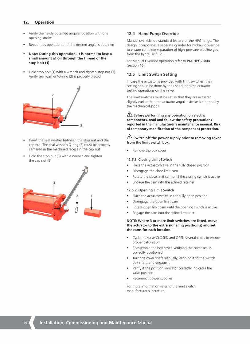
• Verify the newly obtained angular position with one opening stroke
• Repeat this operation until the desired angle is obtained
• Note: During this operation, it is normal to lose a small amount of oil through the thread of the stop bolt (1)
• Hold stop bolt (1) with a wrench and tighten stop nut (3). Verify seal washer / O-ring (2) is properly placed
3
2
• Insert the seal washer between the stop nut and the cap nut. The seal washer / O-ring (2) must be properly centered in the machined recess in the cap nut
• Hold the stop nut (3) with a wrench and tighten the cap nut (5)
52
3
12.4 Hand Pump Override
Manual override is a standard feature of the HPG range. The design incorporates a separate cylinder for hydraulic override to ensure complete separation of high-pressure pipeline gas from the hydraulic fluid.
For Manual Override operation refer to PM-HPG2-004 (section 16).
12.5 Limit Switch Setting
In case the actuator is provided with limit switches, their setting should be done by the user during the actuator testing operations on the valve.
The limit switches must be set so that they are actuated slightly earlier than the actuator angular stroke is stopped by the mechanical stops.
Before performing any operation on electric components, read and follow the safety precautions reported in the manufacturer’s maintenance manual. Risk of temporary modification of the component protection.
Switch off the power supply prior to removing cover from the limit switch box.
• Remove the box cover
12.5.1 Closing Limit Switch
• Place the actuator/valve in the fully closed position
• Disengage the close limit cam
• Rotate the close limit cam until the closing switch is active
• Engage the cam into the splined retainer
12.5.2 Opening Limit Switch
• Place the actuator/valve in the fully open position
• Disengage the open limit cam
• Rotate open limit cam until the opening switch is active
• Engage the cam into the splined retainer
NOTE: Where 3 or more limit switches are fitted, move the actuator to the extra signaling position(s) and set the cams for each location.
• Cycle the valve CLOSED and OPEN several times to ensure proper calibration
• Reassemble the box cover, verifying the cover seal is correctly positioned
• Turn the cover shaft manually, aligning it to the switch box shaft, and engage it
• Verify if the position indicator correctly indicates the valve position
• Reconnect power supplies
For more information refer to the limit switch manufacturer’s literature.
12. Operation
A4US
US
A4
US A4
US
A4

15
Fig 12.4 Typical limit switch box
12.6 Flow Regulator Setting
Flow regulators on manual override are adjusted in factory according to job specific stroking time(s).
In case it is necessary a fine regulation, the following actions should be performed:
• Remove the flow regulator caps by manually unscrewing them
• Rotate the flow regulators, by means of an Allen key, clockwise to lower the flow rate
• Rotate the flow regulators by means of an Allen key, counter-clockwise to increase the flow rate
• Stroke the actuator to verify stroking time(s)
• Perform the previous tuning until reaching the required stroking time(s)
Do not tighten flow regulators completely close: problem of loss of actuator functionality.
Flow regulator
open Flow regulator
close
Hand pump
Fig 12.5 Manual override particular
12.7 Pipeline Gas Power Supply
Verify allowed supply pressure range on actuator label.
Verify medium composition. Contact Rotork to check the compatibility with supply medium.
12.8 Connection to Pipeline
Preliminary operations
• Verify sizes of pipes and fittings according to applicable plant specifications
• Clean the inside of the connection pipes by washing them with a suitable detergent and by blowing air into them
• The connecting pipes must be properly shaped and fixed to prevent stress or loosening of threaded connections
NOTE: For tapered-thread fluid connections, apply a thin layer of thread sealing product (Loctite 577 or equivalent) to ensure a good seal.
Connect the pipeline gas power source in accordance to the applicable operating diagram, please refer to specific job for details.
If isolation valve(s) are not present on the actuator, the end user should install valve(s) with locking facility at the main actuator gas connection port(s).
The connection to the pipeline gas supply depends on the specific operating diagram, an example is shown in the following picture:
Inlet manifold
Isolation valve
Gas connection
Fig 12.6 Single main supply
NOTE: Between the main line and the actuator, the minimum suggested conductor outside diameter is 12 mm (at user’s care).
Refer to specific operating diagram for specific application configuration.
12. Operation
A4 US
US
A4
US
A4
A4 US

Installation, Commissioning and Maintenance Manual16
12.9 Electrical Connections
Check electrical components supply voltage, before start-up.
Access to live electrical conductors is forbidden in hazardous areas unless done under a special permit. Otherwise, all power should be isolated and the unit moved to a non-hazardous area for repair.
Prevent electrostatic charges in potentially explosive areas.
Electrical connection can be performed as follows:
• Remove power supply
• Remove the plastic protection plugs from the cable entries
• Use only appropriately certified reduction fittings, cable glands, fittings and explosion-proof cables
• The cable glands must be tightened in the threaded inlets, to guarantee the waterproof and explosion proof protection
• Pay attention to the correct installation of the O-rings of the cable glands to prevent water and debris infiltration inside electric components
• The size of the electric supply cable must suit the electric power demand
• Insert the connection cables through cable glands and perform assembly according to the cable gland manufacturer’s instructions
• Connect the cable wires to the terminal blocks in accordance with the applicable wiring diagram
• Electric connections must be made by using rigid conduits and trailing cables to prevent mechanical stresses in the cable entries
• On the unused entries of the junction box, replace the plastic plugs with approved metal plugs, in order to guarantee sealing and to comply with explosion safety protection codes
• Assemble the covers of the electric components, paying attention to seals
• Once connections have been completed, check electrical components functionality
Actuator and electrical components must be protected from electrical sparks, lightning, magnetic or electro-magnetic fields, at user’s care.
12.10 Start Up
During the start-up of the actuator, it is necessary to check if:
• Gas supply pressure is as prescribed
• The feed voltage values of electrical components (solenoid valves coils, limit switches, pressure switches etc., if applicable) are as prescribed
• Actuator controls such as remote control, local control, emergency control etc. (if applicable) work properly
• Input remote signals are correct
• The setting of control unit components is according to the plant requirements
• Gas/hydraulic connections show no leakage. If necessary, tighten fittings
• The painted parts have not been damaged during transport, assembling or storage operations. On the contrary, after having removed rust, repair the damaged parts following the applicable painting specifications
• Actuator and all of its parties work as expected
• Operating time is in accordance with requirements
The end user must guarantee equal voltage potential between the valve and the actuator and provide appropriate grounding. The final user shall indicate and maintain the grounding connections on the actuator.
12. Operation
A4US
US
A4
US A4
US
A4

17
12.11 Circuit Gas Venting
In some occasions, example for maintenance, it could be necessary to drain the hydraulic circuit and vent the gas present in the system.
Follow the subsequent instructions:
• Remove electric power supply
• Close the gas supply isolation valve
Isolation valve
Fig 12.7
• Empty the Backup tank (if present) and the Line Break tank (if present) opening the drain valve(s)
• Operate the solenoid valve manual override in both open and close stroke until 0 barg pressure is displayed on the gauge
OpenClose
Fig 12.8
Verify all gas is vented before proceeding with
any further operation.
After gas venting and all other operations have been performed, restore initial conditions:
• Close vent valves of backup tank and line break tank (if present)
• Open the isolation valves of pipeline gas supply.
12. Operation
A4 US
US
A4
US
A4
A4 US
Installation, Commissioning and Maintenance Manual18
Prior to dismounting the actuator, check if any of its parts are still under pressure. The main pressure gauge on the gas block must indicate 0 barg.
• Verify that the backup tank (if applicable) is depressurized otherwise slowly open the drain valve
• Verify that the reference tank (if applicable) is depressurized otherwise slowly open the drain valve
• Verify that the Local/remote selectors are in the remote position
Used hydraulic fluid must be disposed of safely in accordance with the local environmental laws and regulations.
• Dismount the actuator, separate and divide the various parts and components according to the type of material
• Dispose of the pieces of steel, cast iron and aluminum alloys as metal scraps
• Dispose of the rubber, PVC, resins etc. separately, in accordance with the existing national and regional regulations
• Electric components are to be separately disposed of on specialized disposal sites
Actuators manufactured after 1993 year do not contain asbestos or its by-products.
If your Rotork actuator has been correctly installed and sealed, it will give years of trouble-free service. Should you require technical assistance or spares, Rotork guarantees the best service in the world. Contact your local Rotork representative or the factory direct at the address on the nameplate, quoting the actuator type and serial number.
Some actuators have a special spare parts list. Refer to the project specific documentation for further details
13. Dismantling and Disposal 14. Rotork Sales and Service
A4US
US
A4
US A4
US
A4
19
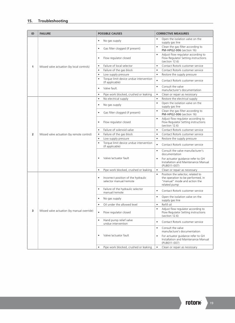
15. Troubleshooting
ID FAILURE POSSIBLE CAUSES CORRECTIVE MEASURES
1 Missed valve actuation (by local controls)
• No gas supply• Open the isolation valve on the
supply gas line
• Gas filter clogged (If present)• Clean the gas filter according to
PM-HPG2-006 (section 16)
• Flow regulator closed• Adjust flow regulator according to
Flow Regulator Setting instructions (section 12.6)
• Failure of local selector • Contact Rotork customer service
• Failure of the gas block • Contact Rotork customer service
• Low supply pressure • Restore the supply pressure
• Torque limit device undue intervention (If applicable)
• Contact Rotork customer service
• Valve fault.• Consult the valve
manufacturer’s documentation
• Pipe work blocked, crushed or leaking • Clean or repair as necessary
2 Missed valve actuation (by remote control)
• No electrical supply • Restore the electrical supply
• No gas supply• Open the isolation valve on the
supply gas line
• Gas filter clogged (if present)• Clean the gas filter according to
PM-HPG2-006 (section 16)
• Flow regulator closed• Adjust flow regulator according to
Flow Regulator Setting instructions (section 12.6)
• Failure of solenoid valve • Contact Rotork customer service
• Failure of the gas block • Contact Rotork customer service
• Low supply pressure • Restore the supply pressure
• Torque limit device undue intervention (If applicable)
• Contact Rotork customer service
• Valve / actuator fault
• Consult the valve manufacturer’s documentation
• For actuator guidance refer to GH Installation and Maintenance Manual (PUB011-007)
• Pipe work blocked, crushed or leaking • Clean or repair as necessary
3 Missed valve actuation (by manual override)
• Incorrect position of the hydraulic selector manual / remote
• Position the selector, related to the operation to be performed, in “manual” mode and action the related pump
• Failure of the hydraulic selector manual / remote
• Contact Rotork customer service
• No gas supply• Open the isolation valve on the
supply gas line
• Oil under the allowed level • Refill oil
• Flow regulator closed• Adjust flow regulator according to
Flow Regulator Setting instructions (section 12.6)
• Hand pump relief valve undue intervention
• Contact Rotork customer service
• Valve / actuator fault
• Consult the valve manufacture’s documentation
• For actuator guidance refer to GH Installation and Maintenance Manual (PUB011-007)
• Pipe work blocked, crushed or leaking • Clean or repair as necessary
A4 US
US
A4
US
A4
A4 US

Installation, Commissioning and Maintenance Manual20
15. Troubleshooting
ID FAILURE POSSIBLE CAUSES CORRECTIVE MEASURES
4 Low stroking time
• Low supply pressure• Restore the correct value of the
supply pressure
• Incorrect flow regulator setting• Adjust the flow regulator to increase
the flow rate (section 12.6)
• High valve / actuator torque
• Consult the valve manufacturer’s documentation
• For actuator guidance refer to GH Installation and Maintenance Manual (PUB011-007)
• Oil under the allowed level. • Refill oil
• Pipe work blocked, crushed or leaking • Clean or repair as necessary.
5 Fast stroking time• High supply pressure
• Restore the correct value of the supply pressure
• Incorrect flow regulator setting• Adjust the flow regulator to reduce the
flow rate (section 12.6)
6 Incorrect valve position• Incorrect setting of mechanical stops
• Check mechanical stop bolts position and adjust if necessary (section 12.3)
• Incorrect signal from limit switches• Check limit switches position
(see 12.5)
7 Leakage
• Worn seals• Replace seals according to
PM-HPG2-009 (section 16)
• Valve / actuator fault
• Consult the valve manufacture’s documentation
• For actuator guidance refer to GH Installation and Maintenance Manual (PUB011-007)
8Incorrect pressure indication by pressure gauge
• Pressure gauge fault• Change Pressure gauge according to
procedure CM-HPG2-001 (section 16)
For other problems, please contact Rotork Customer Service.
A4US
US
A4
US A4
US
A4

21
16. Periodic Maintenance
Rotork recommends performing the following checks to help comply with the rules and regulations of the country of final installation:
Remove pipeline gas supply before proceeding with maintenance operations, discharge accumulators or tanks, except where otherwise indicated.
Periodic Maintenance Schedule
MAINTENANCE ACTIVITY PERIODICITY REFERENCE
Months Years
Visual check of external components and control groups 6
Verify welding. In case of anomalies contact RFS 6
Verify control group cover is closed and locked 6
Check pneumatic connections for leaks. Tighten pipe fittings as required - 1
Cleaning - 1 PM-HPG2-001 page 22
Visual check of painting. Verify absence of damages. Repair if necessary according to painting specification
- 1
Functional test - 1 PM-HPG2 -002 page 23
Check electrical components and grounding connections - 1 PM-HPG2 -003 page 24
Functional test by manual override - 1 PM-HPG2 -004 page 25
Discharge gas dehydrator condensate 6 - PM-HPG2 -005 page 26
Cleaning of gas filter - 1 PM-HPG2 -006 page 27
Gas dehydrator filter elements replacement (if applicable) - 1 PM-HPG2 -007 page 28
Clean the close limt valve gas vent (if applicable) 1 PM-HPG2 -008 page 29
Cylinder seals replacement - 5 PM-HPG2 -009 page 30
Corrective Maintenance Task
In case of fault, according to details in section 15, the following operations could be executed by the end user.
MAINTENANCE ACTIVITY REFERENCE
Replace the pressure gauge on gas control CM-HPG2 -001 page 17
A4 US
US
A4
US
A4
A4 US

Installation, Commissioning and Maintenance Manual22
PM-HPG2-001 Page: 1/1
Component: HPG actuator Task: Cleaning
Equipment, Tools, Materials: Air compressor Project documentation (design and operating pressure values)
Warnings:
Preliminary Operations:
Description:
Remove pipeline gas supply before proceeding.
1. Remove dust from actuator external surface by blowing air
Do not polish / rub non metal surfaces with a dry cloth. The tools and cleaning procedures must not produce sparks or create adverse conditions in the environment during maintenance operations, so as to prevent potential explosion hazards.
Prevent electrostatic charges in potentially explosive areas.
16. Periodic Maintenance
A4US
US
A4
US A4
US
A4

23
PM-HPG2-002 Page: 1/1
Component: HPG actuator Task: Functional test
Equipment, Tools, Materials: ChronometerProject documentation (required stroke times)
Warnings:
Preliminary Operations:
Description:NOTE: Actuator must be connected to the pipeline gas power supply to perform the following test.
1. Operate the actuator2. Perform the stroke several times by local and remote (if applicable) control
Actuator exhausts medium supply in the atmosphere during normal operation. Wear PPD including breathing device in function of type of medium supply used.
3. Verify actuator is correctly working4. Note the stroke time(s)5. Verify stroke time(s) are as required
In case of stroke times out of required range refer to Troubleshooting ID 4, 5 (section 15) to restore.
16. Periodic Maintenance
A4 US
US
A4
US
A4
A4 US

Installation, Commissioning and Maintenance Manual24
PM-HPG2-003 Page: 1/1
Component: HPG actuator (Electrical components) Task: Check electrical components and grounding connections.
Equipment, Tools, Materials: Project documentation
Warnings:
Preliminary Operations:
Description:
Switch off electric power supply before working on electrical devices.Read and follow the safety precautions reported in the manufacturer’s maintenance manual. Risk of temporary modification of the component protection.
Use only antistatic clothes.
1. Remove cover from electric components 2. Check electric device components3. Verify tightness of terminal blocks4. Verify absence of humidity and oxidation5. Check cable gland seals6. Verify grounding connection and restore if necessary
16. Periodic Maintenance
A4US
US
A4
US A4
US
A4

25
PM-HPG2-004 Page: 1/1
Component: Manual override Task: Manual override functional test
Equipment, Tools, Materials: Project documentation
Warnings:
Preliminary Operations:
Description:
Opening operation1. Verify the actuator is not in the completely open position2. Move the remote/local selector (1Z50B) in “local”position (L)
(if present)3. Rotate valve 1V2 clockwise completely until stop to enable
Manual operation4. Shift the hand operated valve 1V1 to the open position5. Operate the hydraulic pump 1P16. Return valve 1V1 to the middle position7. Rotate valve 1V2 counter-clockwise completely until stop to
enable Remote operation8. Move remote/local selector (1Z50B) to the “remote” position
(if present)
Closing operation9. Verify the actuator is not in the completely closed position10. Move the remote/local selector (1Z50B) in “local”position (L)
(if present) 11. Rotate valve 1V2 clockwise completely until stop to enable
Manual operation12. Shift the hand operated valve 1V1 to the close position13. Operate the hydraulic pump 1P114. Return valve 1V1 to the middle position15. Rotate valve 1V2 counter-clockwise completely until stop to
enable Remote operation16. Move remote/local selector (1Z50B) to the “remote” position
(if present)
Close open
Valve 1V2
Pump 1P1
Valve 1V1
16. Periodic Maintenance
A4 US
US
A4
US
A4
A4 US

Installation, Commissioning and Maintenance Manual26
PM-HPG2-005 Page: 1/1
Component: Dehydrator gas filter (if present) Task: Discharge gas dehydrator condensate
Equipment, Tools, Materials: Project documentationWrench (10 mm)
Warnings:
Preliminary Operations: Circuit Gas Venting (section 12.11)
Description:
Remove the gas supply to prevent unintentional operation. Move the isolation valve(s) on the supply gas line (supplied by RFS or by end user) to the closed position. Lock the valve to prevent unintentional opening.
Consult project specific documentation.
1. Vent the gas circuit according to instructions in Circuit Gas Venting (section 12.11)
2. Carefully loosen the screw of the drain valve and drain the condensate
3. When all condensate has been ejected, tighten the screw4. Open the isolation valve on the supply gas line
Isolation valve
Filter dehydrator
Drain valve
Fig 16.1 Filter dehydrator
16. Periodic Maintenance
A4US
US
A4
US A4
US
A4

27
PM-HPG2-006 Page: 1/1
Component: Mechanical gas filter Task: Cleaning of gas filter
Equipment, Tools, Materials: Wrench (22 mm)Project documentation
Warnings:
Preliminary Operations: Circuit Gas Venting (section 12.11)
Description:
Remove the gas supply to prevent unintentional operation. Move the isolation valve(s) on the supply gas line (supplied by RFS or by end user) to the closed position. Lock the valve to prevent unintentional opening.
1. Vent the gas present in the system according to instructions in Circuit Gas Venting (section 12.11)
2. Ensure that there is no gas pressure in the circuit. The pressure gauge must show 0 barg
3. Unscrew gas filter (1Z20A) (Position and number of filters vary in case of manifold with 1 inlet or 2 inlets), using the wrench.
4. Clean the filter with compressed air5. Check if the filter O-rings are in a good condition; otherwise
replace them6. Lubricate the O-ring with grease (section 18.1)7. Reassemble the gas filter8. Open the manual valve on the supply gas line
Gas Filter 1Z20A
Isolation valve
Isolation valves
Gas Filters: 1Z20A, 1Z20B
16. Periodic Maintenance
A4 US
US
A4
US
A4
A4 US

Installation, Commissioning and Maintenance Manual28
PM-HPG2-007 Page: 1/1
Component: Dehydrator Gas filter Task: Gas dehydrator filter elements replacement (if applicable)
Equipment, Tools, Materials: Air compressorProject documentationWrench (16 mm)Allen wrench (6 mm)
Warnings:
Preliminary Operations: Circuit Gas Venting (section 12.11)
Description:
Remove the gas supply to prevent unintentional operation. Move the isolation valve(s) on the supply gas line (supplied by RFS or by end user) to the closed position. Lock the valve to prevent unintentional opening.
Consult project specific documentation.1. Vent the gas circuit according to instructions in
Circuit Gas Venting (section 12.11)2. Ensure that there is no gas pressure in the circuit. The pressure
gauge must show 0 barg3. Unscrew four hex socket bolts (2)4. Remove bowl (3)5. Unscrew bolt (5)6. Remove filter element (6)7. Clean bowl and drain valve (1)8. Replace filter elements (6) and screw bolt (5) into the body9. Check O-ring (4) is in good conditions, otherwise replace it10. Lubricate the O-ring with grease (section 18.1)11. Reassemble the bowl with flange (3) and fix them screwing
bolts (2)12. Tighten drain valve (1)13. Open the manual valve on the supply gas line
6
5
4
3
1
2
16. Periodic Maintenance
A4US
US
A4
US A4
US
A4

29
PM-HPG2-008 Page: 1/1
Component: Close limit valve Task: Clean the close limit valve gas vent
Equipment, Tools, Materials: Wrench (16 mm)Compressed airProject documentation
Warnings:
Preliminary Operations:
Preliminary actions
1. Consult project specific documentation
Description:
1. Remove the 1/4” BSP gas vent with a 16 mm wrench2. Clean the gas vent with compressed air3. Reinstall the gas vent
Gas vent
Close limit valve
16. Periodic Maintenance
A4 US
US
A4
US
A4
A4 US

Installation, Commissioning and Maintenance Manual30
PM-HPG2-009 Page: 1/4
Component: HPG actuator-High pressure pneumatic cylinder Task: Cylinder seals replacement
Equipment, Tools, Materials: Spare seals WrenchLifting toolsProject documentation
Warnings:
Preliminary Operations: Circuit Gas Venting (section 12.11) Removal from valve
Description:
Remove pipeline gas supply before proceeding.
Preliminary actions
1. Move the actuator to the closed position2. Vent the gas present in the system according to instructions in Circuit Gas Venting (section 12.11)3. Pressure guage must show 0 bar4. Remove the components (e.g. limit switch box, gas storage tank, back-up tank) located on the center body cover, if any5. Remove hydraulic and pipeline gas pipes6. Remove actuator from valve (section 11)7. Position the actuator on a workbench (if possible) or in a stable position
For High pressure pneumatic cylinder seals replacement, refer to GH Installation and Maintenance Manual (PUB011-007)
8. Re-install pipeline gas and hydraulic pipes9. Install the components (e.g., limit switch box, gas storage tank) located on the center body cover if any10. The actuator must be tested before it is assembled on the valve11. Cycle the actuator several times, using exclusively dry nitrogen gas, to check functionality and absence of leakages12. Check that the painted parts have not been damaged during disassembly and /or reassembly13. If necessary repaint them in accordance with the applicable painting specifications14. The actuator is now ready to be assembled on the valve
16. Periodic Maintenance
A4US
US
A4
US A4
US
A4

31
CM-HPG2-001 Page: 1/1
Component: Gas Control Task: Replace the Pressure Gauge on Gas Control
Equipment, Tools, Materials: Pressure gaugeWrench (14 mm)
Warnings:
Preliminary Operations: Circuit Gas Venting (section 12.11)
Description:
Remove pipeline gas supply before proceeding.
1. Vent the gas present in the system according to instructions in Circuit Gas Venting (section 12.11)2. Carefully unscrew the pressure gauge3. Replace with another one4. Tighten the pressure gauge5. Connect pipeline gas supply6. Verify that pressure gauge correctly indicate the pressure in the circuit
Pressure Gauge
16. Periodic Maintenance
A4 US
US
A4
US
A4
A4 US

Installation, Commissioning and Maintenance Manual32
For spare part list, refer to GH Installation and Maintenance Manual (PUB011-007).
17. Part List
In general, there is no need to lubricate the actuator because its mechanism is lubricated for life. The standard grease and oil for Rotork scotch yoke actuators is shown below. If an alternative was specified and/or supplied, please refer to the job specific documentation.
18.1 Grease
The following grease is recommended for lubrication of mechanical components of the scotch yoke for temperature range -29 to +60 °C (-20 to +140 °F):
QUANTITY OF GREASE IN HOUSING
Center Body Size Qty (kg/lb)
065 0.3 / 066
085 0.3 / 066
100 0.3 / 066
130 0.4 / 088
160/161 0.5 / 1.10
200/201 0.5 / 1.10
270/271 0.8 / 1.76
350 1.2 / 2.64
MANUFACTURER DOW CORNING CORPORATION
Trade name MOLIKOTE® P40
Color CLEAR BROWN
Unworked Penetration (ISO 2137) 310-350 mm/10
Viscosity of Oil at 40 °C (104 °F) (DIN 51 562) 360 mm²/s
Service Temperature -40 to 230 °C (-40 to 446 °F)
Drop Point (ISO 2176) NONE
Four Ball Tester
Weld Load (Din 51 350 pt.5) 3000 N
Wear Scar Under 800 N Load ( Din 51 350 pt.5) 0.94 mm
Coefficient of Friction[1]
Screw Test - µ Thread 0.16
Screw Test - µ Head 0.08
1 Coefficient of friction in bolted connection, M12x1.75, 8.8, on blackened surface
The following grease is recommended for lubrication of mechanical components of the scotch yoke for temperature range -46 to +40 °C (-51 to +104 °F):
Manufacturer MOBIL
Trade name MOBILTEMP®SHC 100TM
NLGI Grade 2
Colour CLEAR BROWN
Penetration, Density, Viscosity
Worked Penetration at 25 °C (77 °F) (ASTM D 217) 280
Viscosity of Oil at 40 °C ( 104 °F) ASTM D445) 100 cSt
Temperature
Drop Point (ASTM D 2265) >260 °C (>500 °F)
Load - Carrying Capacity, Wear Protection, Service Life
Four Ball Tester (ASTM D 2266) 0.4 mm
Weld Load (ASTM D 2596) >200
Corrosion Protection (ASTM D6138) 0
18. Grease and Hydraulic Oil Specification
A4US
US
A4
US A4
US
A4
33
18. Grease and Hydraulic Oil Specification
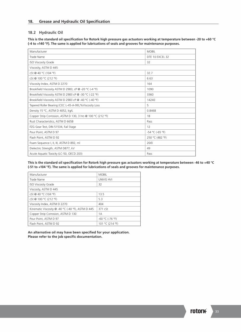
18.2 Hydraulic Oil
This is the standard oil specification for Rotork high pressure gas actuators working at temperature between -20 to +60 °C (-4 to +140 °F). The same is applied for lubrications of seals and grooves for maintenance purposes.
Manufacturer MOBIL
Trade Name DTE 10 EXCEL 32
ISO Viscosity Grade 32
Viscosity, ASTM D 445
cSt @ 40 °C (104 °F) 32.7
cSt @ 100 °C (212 °F) 6.63
Viscosity Index, ASTM D 2270 164
Brookfield Viscosity ASTM D 2983, cP @ -20 °C (-4 °F) 1090
Brookfield Viscosity ASTM D 2983 cP @ -30 °C (-22 °F) 3360
Brookfield Viscosity ASTM D 2983 cP @ -40 °C (-40 °F) 14240
Tapered Roller Bearing (CEC L-45-A-99),%Viscosity Loss 5
Density 15 ºC, ASTM D 4052, kg/L 0.8468
Copper Strip Corrosion, ASTM D 130, 3 hrs @ 100 °C (212 °F) 1B
Rust Characteristics, ASTM D 665B Pass
FZG Gear Test, DIN 51534, Fail Stage 12
Pour Point, ASTM D 97 -54 °C (-65 °F)
Flash Point, ASTM D 92 250 °C (482 °F)
Foam Sequence I, II, III, ASTM D 892, ml 20/0
Dielectric Strength, ASTM D877, kV 49
Acute Aquatic Toxicity (LC-50, OECD 203) Pass
This is the standard oil specification for Rotork high pressure gas actuators working at temperature between -46 to +40 °C (-51 to +104 °F). The same is applied for lubrications of seals and grooves for maintenance purposes.
Manufacturer MOBIL
Trade Name UNIVIS HVI
ISO Viscosity Grade 32
Viscosity, ASTM D 445
cSt @ 40 °C (104 °F) 13.5
cSt @ 100 °C (212 °F) 5.3
Viscosity Index, ASTM D 2270 404
Kinematic Viscosity @ -40 °C (-40 °F), ASTM D 445 371 cSt
Copper Strip Corrosion, ASTM D 130 1A
Pour Point, ASTM D 97 -60 °C (-76 °F)
Flash Point, ASTM D 92 101 °C (214 °F)
An alternative oil may have been specified for your application. Please refer to the job specific documentation.
A4 US
US
A4
US
A4
A4 US

Rotork plcBrassmill Lane, Bath, UK
tel +44 (0)1225 733200email [email protected]
As part of a process of on-going product development, Rotork reserves the right to amend and change specifications without prior notice. Published data may be subject to change. For the very latest version release, visit our website at www.rotork.com
The name Rotork is a registered trademark. Rotork recognises all registered trademarks. Published and produced in the UK by Rotork. POWJB0720
PUB016-003-00Issue 08/20
www.rotork.com
A full listing of our worldwide sales and service network is available on our website.
A4US
US
A4
US A4
US
A4
A4 US
US
A4
US
A4
A4 US