hp smart/zero client 4.1h10032. · hp smart/zero client 4.1.2 ... in the confirm installation...
TRANSCRIPT

HP Smart/Zero Client 4.1.2
Administrator's Guide

© Copyright 2011, 2012 Hewlett-PackardDevelopment Company, L.P. The informationcontained herein is subject to changewithout notice.
Microsoft, Windows, and Vista aretrademarks of Microsoft Corporation in theU.S. and other countries.
The only warranties for HP products andservices are set forth in the express warrantystatements accompanying such products andservices. Nothing herein should beconstrued as constituting an additionalwarranty. HP shall not be liable for technicalor editorial errors or omissions containedherein.
This document contains proprietaryinformation that is protected by copyright.No part of this document may bephotocopied, reproduced, or translated toanother language without the prior writtenconsent of Hewlett-Packard Company.
Third Edition (August 2012)
First Edition (June 2011)
Document Part Number: 654363–003

About This Book
WARNING! Text set off in this manner indicates that failure to follow directions could result in bodilyharm or loss of life.
CAUTION: Text set off in this manner indicates that failure to follow directions could result in damageto equipment or loss of information.
NOTE: Text set off in this manner provides important supplemental information.
If you have comments, feedback, or questions about this guide, please e-mail us [email protected].
iii

iv About This Book
Table of contents
1 Quick Start ....................................................................................................................... 1
Installing HP Smart Client Services .............................................................................................. 2Standard installation .................................................................................................. 2
Booting client .......................................................................................................................... 3Quick troubleshooting ............................................................................................................... 3
2 Server setup ..................................................................................................................... 4
How it works ........................................................................................................................... 4HP Smart Client Services ........................................................................................................... 5
Supported operating systems ...................................................................................... 5Prerequisites ............................................................................................................. 6
Installing Internet Information Services (IIS) ..................................................... 6.NET Framework 3.5 .................................................................................. 8
How to install via Add Windows features ....................................... 8Web download (Windows XP, Windows Vista®, WindowsServer 2003) .............................................................................. 9
Using HP Smart Client Services ................................................................................. 10Installing custom setup .............................................................................. 10Modifying, adding, repairing, or deleting HP Smart Client Services features .... 11
Using Profile Editor ................................................................................................................. 13Changing your server/URL ....................................................................................... 14Configuring platform settings .................................................................................... 14Modifying client settings ........................................................................................... 15
How to use the tree view ........................................................................... 16Changing settings ..................................................................... 16Changing the keyboard language ............................................... 16
How to read the side information bar ......................................................... 18Common settings to change ....................................................................... 18Disabling and enabling items .................................................................... 18
Disabling Configure menu items .................................................. 19Disabling Additional Configurations menu items ............................ 20Finishing and saving your settings ............................................... 21
v

Attaching client files to a profile ................................................................................ 21About installing certificates ........................................................................ 21Installing Citrix Certificates on Smart Zero Core 4.1.0 and earlier versions ..... 22Customized login screen ........................................................................... 22
Screen background customization ............................................... 22Login dialog customization ......................................................... 28
Saving profiles ........................................................................................................ 30Parallel and serial printer port setup .......................................................................... 30
Automatic intelligence ............................................................................................................. 31Viewing your HP Smart Client Services website ........................................................... 32Automatic Intelligence directory structure .................................................................... 32MAC address-based profile ...................................................................................... 32Updating thin clients ................................................................................................ 33
Broadcast update ..................................................................................... 33DHCP Tag setup on Windows Server 2003/2008 for Automatic Intelligenceupdate .................................................................................................... 34DNS alias ............................................................................................... 37Manual update ........................................................................................ 37
HP Intelligent Delivery Service .................................................................................................. 39HP Device Manager ............................................................................................................... 41
3 Client Usage ................................................................................................................... 42
Demo mode (no server configured) ........................................................................................... 42Connections .......................................................................................................................... 43
RDP ....................................................................................................................... 43ICA ....................................................................................................................... 44VMware View ........................................................................................................ 44
Connecting to VMware View ..................................................................... 44Using the System Control pane ................................................................................................ 45
Shutdown/restart .................................................................................................... 45Control panel ......................................................................................................... 46
Control panel menu .................................................................................. 46Parallel and serial printer mapping ............................................................. 48
System information .................................................................................................. 49Status tab ................................................................................................ 50Network tab ............................................................................................ 51Net Tools tab ........................................................................................... 51System Information tab .............................................................................. 53System Logs tab ....................................................................................... 53
Status icon ............................................................................................................. 54USB boot .............................................................................................................................. 54
vi

Download image off web ......................................................................................... 54Reimage device ...................................................................................................... 54
Retrieving System Diagnostics .................................................................................................. 55What is System Diagnostics? .................................................................................... 55Saving System Diagnostics ....................................................................................... 55Opening System Diagnostics .................................................................................... 56
Windows ................................................................................................ 56Linux/Unix .............................................................................................. 57
What to look for in System Diagnostics ...................................................................... 57
vii

viii

1 Quick Start
If you just want to install HP Smart Client Services and get started, this section will guide you throughthe following:
● Installing HP Smart Client Services on page 2
● Booting client on page 3
● Quick troubleshooting on page 3
NOTE: Microsoft® Internet Information Services (IIS) in Windows® Server and Microsoft .NETFramework 3.5 must be installed before you install HP Smart Client Services. For information oninstalling IIS, visit http://www.microsoft.com. If you have internet access, the HP Smart Client Servicesinstallation wizard offers to install the .NET Framework 3.5 for you. If you do not have internet access,you must manually install the Microsoft .NET Framework 3.5. Download Microsoft .NET Framework 3.5from the Microsoft website at http://www.microsoft.com/downloads/en/details.aspx?FamilyId=333325fd-ae52-4e35-b531-508d977d32a6&displaylang=en.
1

Installing HP Smart Client Services
Standard installation
NOTE: Microsoft IIS and Microsoft .NET Framework 3.5 must be installed before you install HP SmartClient Services.
1. Download HP Smart Client Services from HP.com.
2. Double-click HPSmartClientService_version number.exe to launch the HP Smart Client Servicesinstallation wizard.
The InstallShield Wizard dialog box appears.
3. Select the language and click OK.
The Welcome to the InstallShield Wizard for HP Smart Client Service dialog boxappears.
4. Click Next to continue.
The Setup Type page opens.
5. Select Complete setup type, and click Next.
6. Select a connection type, and then click Next to continue.
7. Type the server URL in the field and click Next.
The Select Features page opens.
8. Check the appropriate box or boxes if you want Japanese and Chinese language support. ClickNext to continue.
The Ready to Install the Program dialog box appears.
9. Click Install to install HP Smart Client Services.
If you do not want to install HP Smart Client Services at this time, click Back to make changes orCancel to cancel installation.
If you click Install, HP Smart Client Services is installed and the InstallShield WizardComplete page opens.
10. If you want to launch the Profile Editor, select the check box and click Finish. If not, leave thecheck box clear and click Finish to exit the wizard.
NOTE: The Profile Editor allows you to create and edit configuration files. For more information,see Using Profile Editor on page 13.
2 Chapter 1 Quick Start

Booting clientIf HP Smart Client Services is enabled and configured to connect clients to a valid remote connectionserver, the client will auto-configure and boot to a login screen. Users can then enter their credentials tolog in to the preconfigured remote connection server. If HP Smart Client Services is not enabled, userswill boot to the Demo Mode.
For more information, see Client Usage on page 42.
Quick troubleshootingOccasionally, everything does not go as planned. If you have gone through the previous sections butHP Smart Client Services is not working, a number of additional actions can be taken to resolve theproblem. In this section, we will step through each point in the update process, verify that it is working,and provide resolution guidance if the process is not working.
1. Test network connectivity:
a. Go to the Net Tools tab under System Information.
b. Select the Ping tool, type the server address under Target Host, and then click StartProcess.
If the ping is successful, you should receive output similar to this:
PING 10.30.8.52 (10.30.8.52) 56(84) bytes of data.
64 bytes from 10.30.8.52: icmp_seq=1 ttl=64 time=0.815 ms
64 bytes from 10.30.8.52: icmp_seq=2 ttl=64 time=0.735 ms
If you have a long delay with no output, your network may be disconnected.
c. Check the network cable and network settings in the Control Panel and system tools.
d. Try pinging other servers or clients.
e. If you can reach other clients on the network but not the server, ensure that you have thecorrect server address.
f. Try pinging by IP address instead of Domain name or vice-versa.
g. In some rare cases, ping may be blocked on your network. If that is the case, skip to the nextstep.
2. Check logs: The Smart Client Services log should give a clear indication if there are any problemswith the way the Smart Client server is set up.
a. Verify that there are no errors in the Smart Client Services logs.
b. If an Error: Server is not setup notification appears, verify that the Smart Client Server isset up properly and Smart Client Services is running.
Booting client 3

2 Server setup
● How it works on page 4
● HP Smart Client Services on page 5
● Using Profile Editor on page 13
● Automatic intelligence on page 31
● HP Intelligent Delivery Service on page 39
How it worksThe HP Smart Client is designed to detect its update server automatically and to configure itselfautomatically on first boot. This greatly simplifies device installation and maintenance. Refer to thefollowing diagram to see how the device communicates with the server to receive its profile and clientkits.
4 Chapter 2 Server setup

HP Smart Client Services● Supported operating systems on page 5
● Prerequisites on page 6
● Using HP Smart Client Services on page 10
Supported operating systems
● Windows 7
● Windows Server 2003
● Windows Server 2008
● Windows Server 2008 R2
NOTE: The installer is 32-bit only, but it is supported on 32-bit and 64-bit versions of the Windowsoperating system.
HP Smart Client Services 5

Prerequisites
● Installing Internet Information Services (IIS) on page 6
● .NET Framework 3.5 on page 8
Installing Internet Information Services (IIS)
IIS must be installed before HP Smart Client Services can be installed.
Installing IIS on Windows 7:
1. Click Start and select Control Panel.
2. Click Programs, and then click Turn Windows features on or off.
3. In the Windows Features dialog box, click Internet Information Services. and then clickOK.
Installing IIS on Windows Server 2003:
1. Click Start and select Control Panel.
2. Double-click Add or Remove Programs.
3. Click Add/Remove Windows Components.
4. In the Windows Component Wizard under Components, select Application Server,and then click Next.
5. When the wizard has completed the installation, click Finish.
6 Chapter 2 Server setup

Installing IIS on Windows Server 2008 or Windows Server 2008 R2
1. Click Start, select Administrative Tools, and then click Server manager.
2. Click Roles in the left pane.
3. In Roles Summary, click Add Roles in the right pane.
4. In the Select Server Roles dialog box, check the Web Server (IIS) check box.
5. Accept the default entries and click Next.
HP Smart Client Services 7

6. In the Confirm Installation Selections dialog box, click Install.
7. When the Installation Succeeded screen appears, click Close to end the installation.
.NET Framework 3.5
If you plan to use Windows Server 2008 R2, IIS must be installed before .NET Framework 3.5 isenabled.
You do not have to manually install the .NET Framework 3.5 if you have internet access during theinstallation of HP Smart Client Services. The installation wizard asks you if you would like to installthe .NET Framework 3.5. If you select to install, the process downloads and installs the .NETFramework 3.5 without any user intervention. Users installing HP Smart Client Services without internetaccess must manually install the Microsoft .NET Framework 3.5. The procedures to install the .NETFramework 3.5 are below.
● How to install via Add Windows features on page 8
● Web download (Windows XP, Windows Vista®, Windows Server 2003) on page 9
How to install via Add Windows features
Windows 7 Operating System—The Microsoft .NET Framework 3.5 is already installed inWindows 7.
To verify installation:
1. Click Start > Control Panel.
2. Click Programs, and then click Turn Windows features on or off.
3. If the Microsoft .NET Framework 3.5 option box is checked, then it is already installed.
If it is not checked, check the option box and click OK to turn the feature on.
Windows Server 2008 R2 Operating System—The Microsoft .NET Framework 3.5 is alreadyinstalled in Windows Server 2008 R2.
To verify installation:
1. Click Start > All Programs > Administrative Tools, and then select Server Manager.
8 Chapter 2 Server setup

2. Click Features to display all the installed Features in the right hand pane.
If .NET Framework 3.5 is listed, it is installed.
3. If it is not installed, install it using one of the following methods:
Through the Server Manager interface:
a. In the Server Manager interface, select Add Features to display a list of possiblefeatures.
b. In the Select Features interface, expand .NET Framework 3.5 Features.
c. Select .NET Framework 3.5 and click Next.
d. In the Confirm installation Selections dialog box, click Install.
e. Allow the installation to complete, and then click Close.
Using the command prompt:
a. Click Start > Programs > Accessories.
b. Right-click Command Prompt and select Run as Administrator.
c. In the command prompt, type Import-Module ServerManager, and then press Enter.
d. Type Add-WindowsFeature as-net-framework, and then press Enter.
An exit code as Success for .NET Framework 3.5. appears if installation was successful.
e. Type exit, and then press Enter to exit the Command Prompt.
Web download (Windows XP, Windows Vista®, Windows Server 2003)
If you do not have internet access, you must manually install the Microsoft .NET Framework 3.5.Download Microsoft .NET Framework 3.5 from the Microsoft website at http://www.microsoft.com/downloads/en/details.aspx?FamilyId=333325fd-ae52-4e35-b531-508d977d32a6&displaylang=en.
HP Smart Client Services 9

Using HP Smart Client Services
To launch HP Smart Client Services, double-click HPSmartClientService_version number.exe (HP SmartClient Services installation executable).
● Installing custom setup on page 10
● Modifying, adding, repairing, or deleting HP Smart Client Services features on page 11
Installing custom setup
NOTE: Microsoft IIS and Microsoft .NET Framework 3.5 must be installed before you install HP SmartClient Services.
This is a custom installation of HP Smart Client Services.
1. Download HP Smart Client Services from HP.com.
2. Double-click HPSmartClientService_version number.exe to launch the HP Smart Client Servicesinstallation wizard.
The InstallShield Wizard dialog box appears.
3. Select the language and click OK.
The Welcome to the InstallShield Wizard for HP Smart Client Service dialog boxappears.
4. Click Next to continue.
The Setup Type page opens.
5. Select Custom setup type, and then click Next to continue.
6. Click Next to accept the default folder where setup will install files.
The Select Features page opens.
7. Select the features you want to install, and then click Next to continue.
8. Select a connection type, and then click Next to continue.
9. Type the server URL in the field and click Next.
The Select Features page opens.
10. Check the appropriate box or boxes if you want Japanese and Chinese language support. ClickNext to continue.
The Ready to Install the Program dialog box appears.
11. Click Install to install HP Smart Client Services.
If you do not want to install HP Smart Client Services at this time, click Back to make changes orCancel to cancel installation.
10 Chapter 2 Server setup

If you click Install, HP Smart Client Services is installed and the InstallShield WizardComplete page opens.
12. If you want to launch the Profile Editor, select the check box and click Finish. If not, leave thecheck box clear and click Finish to exit the wizard.
NOTE: The Profile Editor allows you to create and edit configuration files. For more information,see Using Profile Editor on page 13.
Modifying, adding, repairing, or deleting HP Smart Client Services features
You can modify, add, delete, or repair HP Smart Client Services features as needed.
1. Open the HP Smart Client Service – InstallShield Wizard using one of the followingmethods:
● Double-click the HP Smart Client Services setup icon.
● Use the Control Panel.
a. Click Start and open the Control Panel.
b. Double-click Uninstall a program to open a list of programs. Right-click HP SmartClient Service and select Change to open the HP Smart Client ServiceInstallShield Wizard.
2. Modify the installation, if you want to add a feature.
a. Select Modify, and then click Next.
b. Select features to install. Click a check box to select a feature and clear a check box todeselect a feature. Click Next.
If you selected the Automatic Intelligence feature, a Files in Use dialog box appears.
c. If a Files in Use dialog box appears, select one of the options and click OK.
The Maintenance Complete dialog box appears.
d. Click Finish.
HP Smart Client Services 11
3. Repair the installation if you have corrupted or deleted install files. Choose this option to perform acomplete reinstallation of HP Smart Client Services.
a. Select Repair, and then click Next.
The Maintenance Complete dialog box appears.
b. Click Finish.
4. Remove HP Smart Client Services if you wish to remove all installed features.
NOTE: Profiles and packages are not deleted by default.
a. Select Remove and click Next.
HP Smart Client Services is uninstalled and the Uninstall Complete page opens.
b. If you want to Uninstall all the HP Smart Client Service profiles and packages,select the check box and click Finish. If not, leave the check box clear and click Finish toexit the wizard.
12 Chapter 2 Server setup
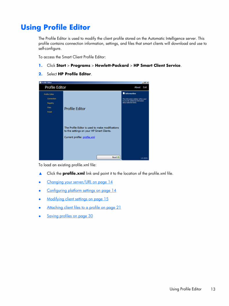
Using Profile EditorThe Profile Editor is used to modify the client profile stored on the Automatic Intelligence server. Thisprofile contains connection information, settings, and files that smart clients will download and use toself-configure.
To access the Smart Client Profile Editor:
1. Click Start > Programs > Hewlett-Packard > HP Smart Client Service.
2. Select HP Profile Editor.
To load an existing profile.xml file:
▲ Click the profile.xml link and point it to the location of the profile.xml file.
● Changing your server/URL on page 14
● Configuring platform settings on page 14
● Modifying client settings on page 15
● Attaching client files to a profile on page 21
● Saving profiles on page 30
Using Profile Editor 13

Changing your server/URL
This page allows you to configure the connection launched from the clients.
▲ Select a connection type and type the server name or address of the remote connection server inthe field.
NOTE: If you choose more than one connection type, the registry tab uses the smallest group ofsettings available in all platforms. Be sure to create one profile for each hardware type. Select theoperating system version used for that profile.
NOTE: If you install a Client Kit, the additional registry settings display in the clients kit's box and areautomatically displayed in the registry tab.
Configuring platform settings
Use the Platform page to select and configure the following:
● Smart Client software versions incorporated in the edited system profile
● Smart Client software versions compatible with the hardware used on your site
● Optional client kits that provide additional registry settings
14 Chapter 2 Server setup
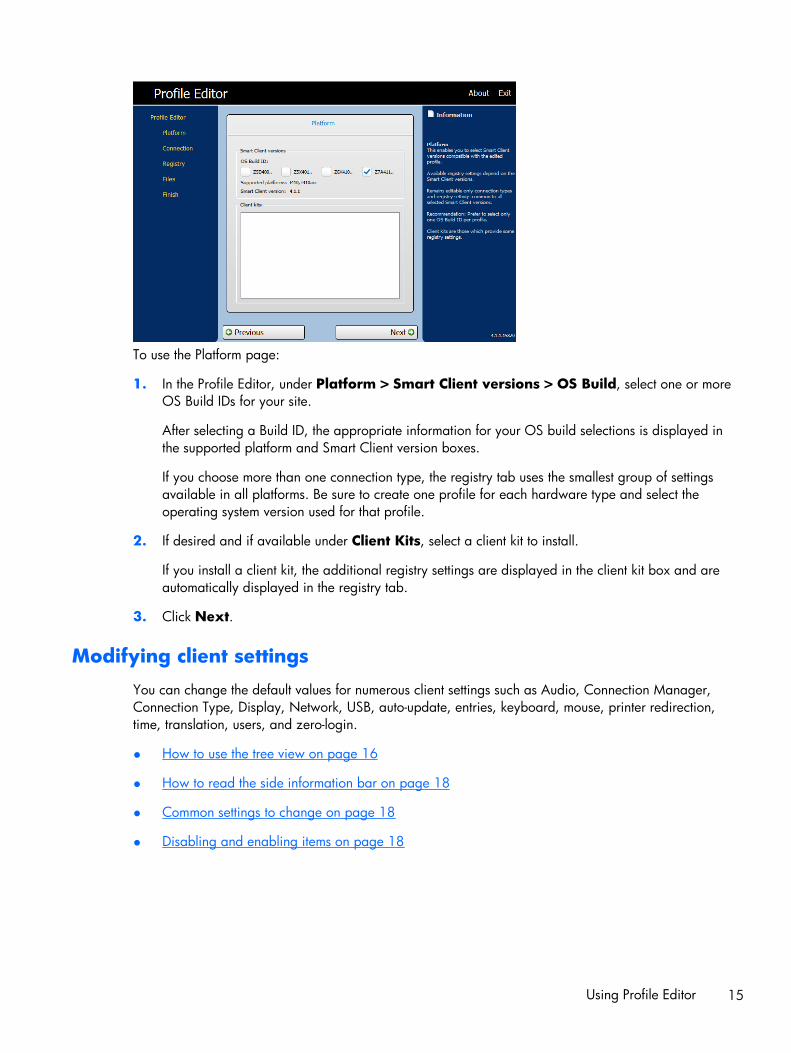
To use the Platform page:
1. In the Profile Editor, under Platform > Smart Client versions > OS Build, select one or moreOS Build IDs for your site.
After selecting a Build ID, the appropriate information for your OS build selections is displayed inthe supported platform and Smart Client version boxes.
If you choose more than one connection type, the registry tab uses the smallest group of settingsavailable in all platforms. Be sure to create one profile for each hardware type and select theoperating system version used for that profile.
2. If desired and if available under Client Kits, select a client kit to install.
If you install a client kit, the additional registry settings are displayed in the client kit box and areautomatically displayed in the registry tab.
3. Click Next.
Modifying client settings
You can change the default values for numerous client settings such as Audio, Connection Manager,Connection Type, Display, Network, USB, auto-update, entries, keyboard, mouse, printer redirection,time, translation, users, and zero-login.
● How to use the tree view on page 16
● How to read the side information bar on page 18
● Common settings to change on page 18
● Disabling and enabling items on page 18
Using Profile Editor 15

How to use the tree view
To display the tree view:
▲ Expand the root and expand the options whose value you want to change.
Changing settings
To change a setting:
Record volume is changed for this example
1. Expand the root and Audio.
2. Click RecordVolume to select it.
3. In the Values area for RecordVolume, change the value as desired.
4. Click Next.
Changing the keyboard language
NOTE: If you are use Profile Editor to modify or set up keyboards languages, you must also changethree registry entries:
/root/keyboard/model
/root/keyboard/layout
/root/keyboard/variant
Keyboard Model Layout Variant
Belgium [Français (Belgique)] pc105 be wincompat
Brazil [Português do Brasil] abnt2 br wincompat
Bulgaria [Български] pc105 bg wincompat
16 Chapter 2 Server setup

Keyboard Model Layout Variant
Canada [Français Canadien] pc105 ca wincompat
Croatia [Hrvatski] pc105 hr wincompat
Czech Republic [Český] pc105 cz wincompat
Denmark [Dansk] pc105 dk wincompat
Finland [Suomi] pc105 fi wincompat
France [Français] pc105 fr wincompat
Germany [Deutsch] pc105 de wincompat
Hungary [Magyar] pc105 hu wincompat
Italy [Italiano] pc105 it wincompat
Japan, with "¥" (RDP) [日本語] jp106 jp jp106-hp-yen
Japan, with "\" (RGS) [日本語] jp106 jp jp106-hp
Korea [한국어] kr106 kr wincompat
Latin America [América Latina] pc105 latam wincompat
Netherlands [Nederlands] pc105 nl wincompat
Norway [Norsk] pc105 no wincompat
Poland [Polski] pc104 pl wincompat
Portugal [Português] pc105 pt wincompat
Romania [Română] pc105 ro wincompat
Russia [Русский] pc104 ru wincompat
Slovakia [Slovenčina] pc105 sk wincompat
Slovenia [Slovenščina] pc105 si wincompat
Spain [Español] pc105 sp wincompat
Sweden [Svenska] pc105 se wincompat
Switzerland [Français (Suisse)] pc105 ch wincompat-fr_ch
Switzerland [Deutsch (Schweiz)] pc105 ch wincompat-de_ch
Turkey [Türkçe] pc105 tr wincompat
Ukraine [Українська] pc105 ua wincompat
United Kingdom [English] pc105 gb wincompat
United States [English] pc104 us wincompat
United States [English], Dvorak pc105 us wincompat-dvorak
United States [English], International pc105 us wincompat-intl
Using Profile Editor 17

How to read the side information bar
The Information bar is located in the right pane of the Profile Editor screen. When you select anoption, information on the setting appears in the Information bar.
Common settings to change
● Audio
● Connection Manager
● Connection Type
● Display
● Network
● Auto-update
● Mouse
● Screensaver
● Time
● Translation
Disabling and enabling items
● Disabling icons
● Disabling Configure menu items
● Disabling Additional Configurations
● Finishing and saving your settings
18 Chapter 2 Server setup

Disabling Configure menu items
To disable Configure menu items:
1. In the Profile Editor under Registry > Registry Settings, expand the following folders:
● Zero-Login folder
● Controls folder
2. In Registry Settings under Zero-Login > Controls, select the Configure menu option that youwish to disable.
Using Profile Editor 19

3. Select Authorized.
4. To disable a menu option, type 0 in the Value field.
Repeat steps 1–4 for each menu item you want to disable.
Disabling Additional Configurations menu items
All menu items under Additional Configuration must be disabled before Additional Configuration canbe disabled.
To disable Additional Configuration menu items:
1. In the Profile Editor under Registry settings > Users > User > apps, open a folder for themenu item that you want to disable. The table below identifies the menu items associated witheach folder.
Menu Option Folder
Automatic Updates hptc-auto-update
Date and Time hptc-date-mgr
Display Preferences hptc-display-prefs
Sound hptc-mixer
Mouse hptc-mouse
Network hptc-network-mgr
20 Chapter 2 Server setup
Menu Option Folder
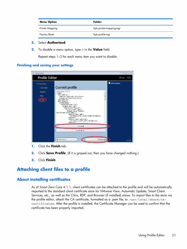
Printer Mapping hptc-printer-mapping-mgr
Factory Reset hptc-profile-mgr
2. Select Authorized.
3. To disable a menu option, type 0 in the Value field.
Repeat steps 1–3 for each menu item you want to disable.
Finishing and saving your settings
1. Click the Finish tab.
2. Click Save Profile. (If it is grayed out, then you have changed nothing.)
3. Click Finish.
Attaching client files to a profile
About installing certificates
As of Smart Zero Core 4.1.1, client certificates can be attached to the profile and will be automaticallyimported to the standard client certificate store for VMware View, Automatic Update, Smart ClientServices, etc., as well as the Citrix, RDP, and Browser (if installed) stores. To import files to the store viathe profile editor, attach the CA certificate, formatted as a .pem file, to /usr/local/share/ca-certificates. After the profile is installed, the Certificate Manager can be used to confirm that thecertificate has been properly imported.
Using Profile Editor 21

Installing Citrix Certificates on Smart Zero Core 4.1.0 and earlier versions
In Smart Zero Core 4.1.0 and earlier, without the Certificate Manager add-on, the only certificate storesupported by the profile editor is the Citrix Certificate store. Other stores require client scripts to be runafter certificate import, and so require a Custom update. In this example, we will install a cacert CAcertificate that will be used by the Citrix session.
1. Add a file.
2. Import the file.
3. Select the desired root certificate (.pem or .crt formats only).
4. Edit the path: /usr/lib/ICAClient/keystore/cacerts/<cert>.
5. Click Save.
Customized login screen
Screen background customization
There is one directory per connection type – plus a default style – that specifies the style elements of theconnection’s background image and login window style. Registry entries specify the directories inwhich these files are stored and can be modified to point to custom directories. For instance, theregistry key root/zero-login/styledir/view points to the directory containing style elements forthe login desktop for VMware View connections, defaulting to /etc/hptc-zero-login/styles/view.
Within a style’s directory, the file bgConfig.rtf specifies the elements in the desktop's backgroundwindow. Syntax of a bgConfig.rtf file is in a stylesheet-like format with some or all of the elementsdescribed below. Each element begins with the element type and then a set of attributes surrounded bybraces, e.g.
global {
color: 666666; # Dark gray
padding: 20; # 20 pixels
}
Any number of image or text elements can be specified. If any gradients are specified, only the last ofthem is used to color the desktop's background; otherwise the color specified in the global section isused. Any line that begins with a number-sign (‘#’) is considered a comment and is ignored, as areblank lines. Text following a semicolon that begins with ‘#’ is also treated as a comment, such as theexamples above.
Each element is assigned a set of attributes such as size, color, and position. Each attribute is specifiedby the attribute name followed by a colon followed by its value[s] followed by a semicolon, all on asingle line. Some of these attributes are common to many element types, and those described first.
Common attributes
name
22 Chapter 2 Server setup

Parameters: a string
Example: name: itemName;
Default: none
Use: Specifies a string to associate with the element. It is used only in debugging output, such as whena syntax or value error is found in attribute parsing.
padding
Parameters: An absolute (pixel) or percentage value
Example: padding: 20;
Default: none
Use: An object will be positioned on the screen as if the screen were smaller on all sides by thepadding value. For instance, if an element would normally be placed at 0,0, with a padding of 20 itwould be placed at 20,20 instead. If specified in the global element, it will apply to all subsequentelements, leaving an empty gutter around the screen edged, unless those elements override the paddingwith their own padding value.
color
Parameters: RRGGBB 6-digit hex value or rrr,ggg,bbb 0-255,0-255,0-255 form
Example: color: ff8800;
Default: 255,255,255 (white)
Use: Specifies the color of the element.
alpha
Parameter: 0-255 integer
Example: alpha: 127;
Default: 255 (fully opaque)
Use: Specifies the opacity of the element. 255 is fully opaque; 0 would be fully transparent, renderingthe element invisible. Elements are layered over the background in the order they are defined.
size
Parameters: WWxHH, where WW is width in absolute pixels or in a percentage of screen width; andHH is height in absolute pixels or in a percentage of screen height.
Example: size: 256x128;
Default: the natural size of the element, e.g., the pixel size of an image.
Use: Specifies the size of the element. Elements will be scaled to match the specified size.
Using Profile Editor 23

position
Parameters: XX,YY where XX and YY are positions in absolute pixels or in percentages of screen widthand height.
Example: position: 50%,90%;
Default: 0,0 (the upper left)
Use: Specifies the position of the element. See alignment below as well.
alignment
Parameters: [left|hcenter|right] [top|vcenter|bottom]
Example: alignment: left bottom;
Default: hcenter vcenter—the element is centered at the given position.
Use: The combination of position and alignment specify both an anchor point for the element and howthe element is aligned relative to that anchor point. For instance, with a position of 90%,70% andalignment of right bottom, the element is positioned so that its right edge is at 90% of the width of thescreen and its bottom edge is at 70% of the height of the screen.
context
Parameters: [login|desktop|all]
Example: context: login;
Default: all
Use: Specifies that the element should only be shown on the login screen for the protocol, on thedesktop screen for the protocol (if any), or on both. Only some protocols (e.g., Citrix XenDesktop) havea desktop screen.
Elements
The element type is given followed by a left-brace. Attributes follow, one on each line. Finally theelement is closed by a right-brace on a single line, e.g.
global {
color: 333344;
padding: 16;
}
global
Use: Specifies global background or padding values.
24 Chapter 2 Server setup

Common attributes recognized: name, color, padding
● color—specifies the solid background color of the screen, if no gradients are specified
● padding—specifies the default padding for all subsequent elements
Custom attributes: none
gradient
Use: Specifies a full-screen gradient for use in the background.
Common attributes recognized: name, context
Custom attributes:
● type
Parameter: [linear|radial]
Example: type: linear;
Default: linear
Use: Linear gradients can be either horizontally-oriented or vertically-oriented; coordinates given incolors are a fraction of width or height. Radial gradients are centered on the screen center;coordinates are a fraction of the distance to the screen edge (top and bottom or left and right).
● axis
Parameter: [height|width]
Example: axis: width;
Default: height
Use: For linear gradients, axis specifies the direction of the gradient (top-to-bottom or left-to-right).For radial gradients, specifies whether the radius of the gradient is half screen height or halfscreen width.
● metric
Parameter: [linear|squared]
Example: metric: linear;
Default: squared
Use: For radial gradients, metric specifies whether the color interpolation between points is donewith a dx2+dy2 distance calculation (squared) or the square root of number (linear). Squaredinterpolation is somewhat quicker to draw.
● colors
Parameter: space-separated list of [value,color] pairs, where value is a [0.0-1.0] floating pointfraction of the axis of measurement (e.g., the width of the screen in a linear width-axis gradient)and color is the color of the gradient at that point. The value runs top-to-bottom for vertical linear
Using Profile Editor 25

gradients; left-to-right for horizontal linear gradients; and center-to-edge for radial gradients.Colors are specified as either six-digit hex or three 0-255 comma-separated values.
Example: colors: 0.0,000000 0.5,996600 0.9,255,255,255;
Use: colors will be interpolated along the linear or radial axis between the points and colorsspecified. If no values are given, the colors are assumed to be evenly spaced on the axis between0.0 and 1.0. If the first fractional value is greater than 0.0, the first color will be used in the spacebetween the screen edge and the first value. Likewise, if the last value is less than 1.0, the lastcolor will be used between the last value and the screen edge. Values must be in increasing sortedvalues, though a value can be repeated for a sharp transition. For instance, “0.0,CCCCCC 0.5,EEEEEE 0.5,660000 1.0,330000” in a vertical linear gradient would specify agradient between light grays on the upper half and dark reds on the lower half.
● dithered
Parameter: [true|false]
Example: dithered: true;
Default: false
Use: If your gradient is showing signs of color-banding, dithering will eliminate this visual artifact.Dithering is not supported for radial gradients with the ‘squared’ metric.
image
Use: Specifies an image to overlay over a portion of the background.
Common attributes recognized: name, size, alpha, position, alignment, context
Custom attributes:
● source
Parameter: file-path
Example: source: /writable/misc/Company_logo.png;
Use: Specifies the absolute pathname to the image file. Many formats are supported, e.g., png,jpg, gif. The image may have transparent regions.
● proportional
Parameter: [true|false]
Example: proportional: false;
Default: true
Use: When true, if the image needs to be scaled to achieve the specified size, its aspect ratio willbe maintained to fit within the rectangle specified. When false, non-proportional scaling is done tomake the image exactly fit the specified size.
text
26 Chapter 2 Server setup

Use: Specifies a string of text to lay over the background.
Common attributes recognized: name, size, color, alpha, position, alignment, context
Custom attributes:
● text-locale
Parameter: localized text
Example: text-de_DE: Dieser Text is in Deutsch.;
Use: When in the matching locale, this text will be used for the string. Supported are de_DE(German), en_US (English), es_ES (Spanish), fr_FR (French), ja_JP (Japanese), and zh_CN(Simplified Chinese). File encoding is UTF-8.
● text
Parameter: default text
Example: text: This will be shown on the screen.;
Use: If no matching localized text is specified, this text string will be used instead. Note: the textrendering engine does not support HTML-style markup.
● font-locale
Parameter: locale-specific fontName
Example: font-ja_JP: kochi-gothic;
Use: When in the matching locale, this font will be used when the string is rendered. See thedescription for text-locale above. The name must match one of the fonts under /usr/share/fonts/truetype. For Japanese text, it may be necessary to select kochi-gothic; for Simplified Chinese text,uming.
● font
Parameter: fontName
Example: font: DejaVuSerif-Bold;
Default: DejaVuSerif
Use: If no matching localized font is specified, this font will be used instead. The name must matchone of the fonts under /usr/share/fonts/truetype.
● font-size
Parameter: pixels (e.g., 20) or percentage of screen height (e.g., 5%) or points (e.g., 12pt)
Example: font-size: 12pt;
Use: Specifies the default size of the font. The text may be further scaled if size, max-width, and/or max-height are specified.
● max-width
Using Profile Editor 27

Parameter: size in pixels or in a percentage of screen width
Example: max-width: 90%;
Use: If the string would otherwise turn out to be wider than the size given, it is scaled down to fitwithin the width specified.
● max-height
Parameter: size in pixels or in a percentage of screen height
Example: max-height: 64;
Use: If the text would otherwise turn out to be taller than the size given, it is scaled down to fit theheight specified.
Login dialog customization
There is one directory per connection type, plus a default style, that specifies the style elements of theconnection’s background image and login window style. Registry entries specify the directories inwhich these files are stored and can be modified to point to custom directories. Within a style’sdirectory, files with the “.qss” suffix customize the style elements of the login area.
qss files are Qt stylesheets and their syntax is described in Qt’s documentation:
● http://doc.trolltech.com/4.6/stylesheet-syntax.html
● http://doc.trolltech.com/4.6/stylesheet-reference.html
Most of the elements in the login area can be customized using qss-style elements. Each has beenassigned an ID so they are easily addressable using the “#elementID” selector.
28 Chapter 2 Server setup
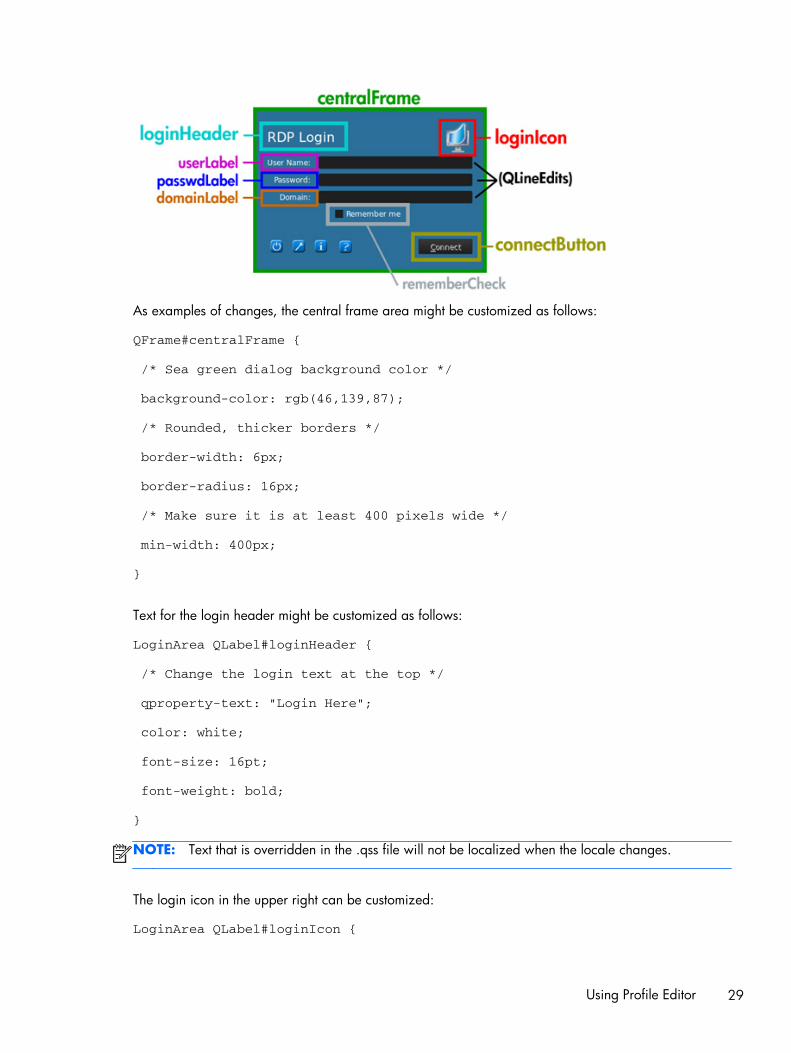
As examples of changes, the central frame area might be customized as follows:
QFrame#centralFrame {
/* Sea green dialog background color */
background-color: rgb(46,139,87);
/* Rounded, thicker borders */
border-width: 6px;
border-radius: 16px;
/* Make sure it is at least 400 pixels wide */
min-width: 400px;
}
Text for the login header might be customized as follows:
LoginArea QLabel#loginHeader {
/* Change the login text at the top */
qproperty-text: "Login Here";
color: white;
font-size: 16pt;
font-weight: bold;
}
NOTE: Text that is overridden in the .qss file will not be localized when the locale changes.
The login icon in the upper right can be customized:
LoginArea QLabel#loginIcon {
Using Profile Editor 29

/* Substitute my company logo for the normal one. */
image: url(/writable/misc/MyCompanyLogo.png);
min-width: 48px;
min-height: 48px;
}
It can have a different style when it is not enabled:
QPushButton#connectButton:disabled {
/* Flat gray */
background: rgb(204,204,204);
border-radius: 3;
color: rgb(102,102,102);
font-size: 12pt;
}
Of course, many more customizations are possible. See the Qt documentation for possibilities.
Saving profiles
This screen shows the contents of the profile and allows it to be saved.
The profile can also be saved by clicking Finish in the Current Profile page of the Profile Editor.
Parallel and serial printer port setup
Parallel and serial printing can be set up in the Profile Editor. Further setup can then be done via thePrinters and Faxes wizard. This only applies to those two printer types; a USB printer is automaticallyconfigured to map when it is plugged in. The Profile Editor requires the first three steps for either serialor parallel printer. Steps 4 to 6 are required only for a serial printer.
NOTE: You will need your serial printer’s baud rate in order to set up the printer. If you do not knowthis, on most printers, you can press and hold the FEED button and turn the printer on. After a fewseconds, release the FEED button and the printer will enter a Testing mode and print out the requiredinformation. You may need to turn the printer off to cancel the Test mode or press FEED again to makeit print the diagnostic page.
1. From the Profile Editor, configure an RDP or VMware View connection.
2. In the Registry Editor, select the Show all settings check box.
3. In the Registry Editor, go to root\ConnectionType\rdesktop\connections\{UUID}\mapSerial orroot\ConnectionType\view\connections\{UUID}\mapSerial and change its value to 1.
30 Chapter 2 Server setup
4. In the Registry Editor, create a new directory under Root called Serial.
5. Under Serial, create a new setting called Baud.
6. Set the Baud value to the baud rate of your serial printer.
NOTE: If you connect using VMware View, as it originally starts to connect, make sure you cancel theconnection. You need to change it—click the down arrow next to the connection, select Connection,and then select Microsoft RDP.
When you connect to your server via RDP or VMware View, use these steps to install the printer:
1. Click Start > Printers and Faxes.
2. Click Add Printer in the new window and click Next.
3. Make sure that Local Printer attached to this Computer is selected and that theAutomatically detect and install my Plug and Play printer check box is cleared, clickNext.
4. In the next window, select a port from the menu.
The port you need is in the section of ports labeled TS###, where ### is a number between000-009, 033-044. The appropriate port depends on your host name and the printer you want toinstall. Example: with a host name of ZTAHENAKOS and a serial printer, select the port with(ZTAHENAKOS: COM1). For a parallel printer, you would select ZTAHENAKOS: LPT1. TheTS### is assigned by the Server, so it will not be the same every time.
5. Select the manufacturer and driver for your printer. If you have the driver disc or want to useWindows Update to install the driver, you may select either of those options instead.
NOTE: For basic/test printing, the Generic Manufacturer and Generic/Text Only printershould be valid in most cases.
If you are asked to keep the existing driver and if it is known to work, then keep it and clickNext.
6. Assign a name to the printer. If you would like to use it as your default printer, select Yes andclick Next.
7. If you would like to share the printer, select Share name and assign it a share name. Otherwise,click Next.
8. On the next page, you may request a test print. This is recommended, as it will verify that theprinter setup is correct. If it is not set up properly, review the settings and try again.
NOTE: If the client disconnects from the Server, the printer will have to be set up again the nexttime the client connects.
Automatic intelligence● Viewing your HP Smart Client Services website on page 32
● Automatic Intelligence directory structure on page 32
Automatic intelligence 31

● MAC address-based profile on page 32
● Updating thin clients on page 33
Viewing your HP Smart Client Services website
To view the HP Smart Client Services website:
1. Click Start > Administrative Tools.
2. Click Internet Information Services Manager.
3. In the left pane, expand the Computer name.
4. Expand the Sites folder.
5. Expand the HP Smart Client Service site.
6. Expand the auto-update folder and its sub folders.
Automatic Intelligence directory structure
NOTE: The index.txt file is no longer supported as of version 4.1.1.
MAC address-based profile
This section covers how to create an Automatic Intelligence update profile for a single MAC addressand how to place that profile on HP Smart Client Services so that it will be downloaded by the client.
Certain devices require different settings based on locations. In this profile type, MAC profile andgeneral profile are merged, with the MAC profile taking precedence.
1. Open the existing general profile using Profile Editor.
2. Modify or add new registry keys as needed for specific device.
3. (Optional) Delete all unnecessary registry keys.
32 Chapter 2 Server setup

4. Use system info from the client to obtain the MAC address.
5. Click Save Profile As and save the profile to HP Smart Client Services (C:\Program Files (x86)\Hewlett-Packard\HP Smart Client Service\auto-update
\PersistentProfile\MAC\<MAC>.xml, e.g., 00fcab8522ac.xml).
6. Reboot the client with that MAC address.
7. Ensure that the settings have been applied.
Updating thin clients
You have four possible methods of updating:
● Broadcast update on page 33
● DHCP Tag setup on Windows Server 2003/2008 for Automatic Intelligence updateon page 34
● DNS alias on page 37
● Manual update on page 37
Broadcast update
Broadcast update, the simplest of the three methods, only requires you to plug the thin client into thesame network as the update server. Broadcast update relies on HP Smart Client Services, anapplication that works with Microsoft Windows IIS to push updates to the thin client. HP Smart ClientServices also includes a Profile Editor to allow profiles to be customized for the thin client.
For Broadcast update to work correctly, HP Smart Client Services must be installed and enabled on theWindows server. HP Smart Client Services can be downloaded from HP.com. Once Smart ClientServices is set up, any thin client with a network connection can communicate with Smart ClientServices and be updated.
NOTE: Broadcast updates only work if the thin client is on the same subnet as the Windows serverwith HP Smart Client Services installed.
To make sure Broadcast Update is working, run the Profile Editor and make some changes. Connect thethin client and verify that it has downloaded the new profile. If it has not, please review Quicktroubleshooting on page 3 for assistance.
Automatic intelligence 33

DHCP Tag setup on Windows Server 2003/2008 for Automatic Intelligenceupdate
DHCP tagging enables you to specify the thin clients to be updated. This is useful if you want onlycertain thin clients to run with a particular update; however, if you only have one or two thin clients toupdate, you may want to consider using Manual update instead. Otherwise, Broadcast update isrecommended.
NOTE: Your server MUST have the DHCP Role installed in order to use DHCP Tagging. If necessary,install the DHCP Role using Server Manager.
The following procedure explains how to do DHCP Tagging from a Windows 2008 R2 Server. Thisspecific server is not required; however, it is recommended that you use one of the operating systemslisted in Supported operating systems on page 5. Other servers may accomplish DHCP Taggingsomewhat differently.
1. Click Start > Administrative Tools > DHCP.
34 Chapter 2 Server setup

2. In the left pane, select the Domain to which the thin clients are connected.
3. Right-click IPv4, and then select Set Predefined Options.
4. In the Predefined Options and Values dialog box, click Add.
5. In the Option Type dialog box:
Automatic intelligence 35

● In the Name field, type auto-update.
● Select String from the Data type menu.
● Type 137 in the Code field.
● Type HP Automatic Update in the Description field.
6. Verify that the information is correct and click OK.
7. In the Value section, type the update server address in the String field.
Example: http://auto-update.domain.com:18287/auto-update
8. Click OK to finish the setup.
DHCP Tagging is now ready to update specific thin clients.
36 Chapter 2 Server setup

DNS alias
During boot, Automatic Update attempts to resolve the DNS alias 'auto-update'. If that hostnameresolves, it attempts to check for updates at the URL http://auto-update:18287. This updatemethod enables clients to access a single update server across the entire domain, simplifyingmanagement for deployments with many subnets and DHCP servers. To configure this method, changethe hostname of the server hosting Smart Client Services to 'auto-update' or create a DNS alias of 'auto-update' for that server.
Manual update
The final method, Manual update, can be used to have a thin client connect to a specific server forupdates. This can be useful if you want to test an update on a single thin client before pushing theupdate to many thin clients or if you have specific updates to be installed on only one or two thinclients.
Manual update is a nice substitute for DHCP Tagging, if you only have a couple of thin clients requiringa specific update. However, if multiple units require specific updates, DHCP Tagging is the betteroption. If no update segregation is required, Broadcast update is the recommended method.
1. Click the wrench icon , and then select Additional Configuration > Automatic Update.
2. In the dialog box that opens, select Enable manual configuration, and then select http fromthe Protocol menu.
Automatic intelligence 37

3. In the Server field, type the host name of the update server with the port.
The format is: autoupdate.domain.com:18287, where auto-update.com is the host name.
4. In the Path field, type auto-update, and click OK. The thin client is now be able pull updatesfrom the specified server.
38 Chapter 2 Server setup

HP Intelligent Delivery ServiceThis Windows service listens for broadcasts from client devices on a high level port. When a broadcastis received, HP Intelligent Delivery Service responds with the URL of the Automatic Intelligence server,which the smart client uses to check for client updates.
To start and stop HP Intelligent Delivery Service:
1. Click Start > Program > Administrative Tools > Server Manager.
2. Expand the Configuration tab in the left pane and select Services.
3. In the center Services pane, select HP Broadcast Server Service.
4. In the right Actions pane, locate HP Broadcast Server Service.
The default settings should have HP Broadcast Server Service started and the startup type setto Automatic.
5. In the center Services pane, double-click or right-click HP Broadcast Server Service andselect Properties.
6. In the HP Broadcast Server Properties dialog box under Service Status, click to start,stop, pause, or resume the service.
To view the service application log for HP Intelligent Delivery Service:
1. Click Start > Program > Administrative Tools > Server Manager.
HP Intelligent Delivery Service 39

2. In the left pane, expand Diagnostics > Event Viewer > Windows Logs, and then selectApplication.
In the center Application pane are logs of all of the application events.
Logs related to HP Intelligent Delivery Service can be viewed under HP Broadcast Server WinService.
Regkeys
Intelligent Delivery uses two registry keys:
● HKLM\SYSTEM\CurrentControlSet\Services\HP Broadcast Server\Port
● HKLM\SYSTEM\CurrentControlSet\Services\HP Broadcast Server\ServerURL
Port is the port that Intelligent Delivery listens for client broadcasts on, during installation that port isautomatically opened in the firewall.
ServerURL is the URL of the Automatic Intelligence server and will be set to http://<local machine IP>:18287/auto-update during installation. It is recommended that a machine with astatic IP be used as the host machine for HP Smart Client Services, as if it changes, the ServerURLregistry key will need to be modified to match the new host.
NOTE: You may also need to open ports in the Antivirus software.
40 Chapter 2 Server setup

HP Device ManagerThe HP Device Manager Agent is software that runs in the background of the thin client. This allows theadministrator to select thin clients remotely and to manipulate those thin clients to meet the requiredbusiness need. For more information on HP Device Manager, refer to the HP Device Manager UserGuide at C:\Program Files\HP\HP Device Manager\Doc\User_Guide. If you do not haveHP Device Manager downloaded or installed yet, you can download it fromhttp://h20000.www2.hp.com/bizsupport/TechSupport/Document.jsp?lang=en&cc=us&objectID=c01490790&prodTypeId=12454&prodSeriesId=4306187.
HP Device Manager 41

3 Client Usage
This hardware and software combination gives the user the power to remotely connect into manyservers with different operating systems. This provides the user with a variety of powerful computersfrom the user’s desk.
Very little hardware setup is required: connect an active network cable, a mouse, a keyboard, and amonitor, and then connect a power cord and plug it into a power outlet. If HP Smart Client Services isenabled and configured to connect clients to a valid remote connection server, the client automaticallyconfigures itself and boots to a login screen. Users can then enter their credentials to log in to thepreconfigured, remote connection server.
● Demo mode (no server configured) on page 42
● Connections on page 43
● Using the System Control pane on page 45
● USB boot on page 54
Demo mode (no server configured)When the client first boots and cannot contact HP Smart Client Services, it will boot into demo mode.This mode allows the user to manually choose the remote connection server and URL. This allows usersto quickly test the unit for a demo or for a very small environment in which a remote configurationservice is not required.
42 Chapter 3 Client Usage

To configure Demo Mode:
1. Click on a connection type.
2. Type the server name or IP address in the appropriate fields.
3. Type in the Server Login and click Log on.
Connections● RDP on page 43
● ICA on page 44
● VMware View on page 44
RDP
The RDP Client is based on freeRDP 1.0 and includes many enhancements to meet requirements for RDP7.1:
● Hardware-accelerated RemoteFX
● MMR supported when connecting to Windows hosts with the Desktop Experience feature enabled(Windows 7 or Windows Server 2008 R2)
● USBR supported when connecting to Windows 7 Remote Desktop Virtual Hosts
● Bidirectional audio
● True multimonitor
Connections 43
ICA
Published application mode
Direct desktop mode
Supported/unsupported features
● Support XenApp 5/6 and XenDesktop four connections
● Standard ThinPro Citrix 12.2.3.211107–1 Linux Client with HDX
● Full 1080p MMR support HDX/Rave
NOTE: The initial 4.1.1 release does not support HDX. To obtain HDX support, install version4.1.2.
● USBR support via HDX
● Published application support
VMware View
Supported/unsupported features
● Standard VMware View 1.4 client on the non-DSP-accelerated PCoIP API client configuration.
NOTE: The VMware View 1.5.1 client is available as a web add-on.
● An alternate configuration is available that contains the DSP-accelerated VMware View PCoIPclient from Teradici. This configuration will have greatly improved PCoIP performance over thestandard VMware View 1.5.1 client.
NOTE: This configuration can be identified by the PCoIP logo in the lower left corner of aVMware View connection user login page.
● No broker smartcard login support.
Connecting to VMware View
To connect with VMware View:
1. Select VMware View from the connection Type list.
2. Type the VMware View connection server name or address in the field and press Enter.
3. Type your user name in the field.
4. Type your password in the field.
5. Type your domain in the field.
6. Click Connect to connect to your View connection server.
44 Chapter 3 Client Usage

7. The Desktop window is displayed with desktop pool/s and/or workstations to which you canconnect. Choose the appropriate desktop and click Connect to continue.
8. Use the Ctrl-Alt-F12 hotkey sequence to disconnect from your PCoIP session and return to the loginscreen.
NOTE: The Ctrl-Alt-F12 command works on the PCoIP-optimized client only.
Using the System Control pane
This section describes the functions in the System Control pane. The topics are as follows:
● Shutdown/restart on page 45
● Control panel on page 46
● System information on page 49
● Status icon on page 54
Shutdown/restart
The Power button is located in the bottom left of the Select Connection Type and Log on screens.
● Reboot button—This reboots the system.
● Power Off button—This powers off the system.
Using the System Control pane 45

Control panel
Control panel menu
The Control Panel button is the button with the wrench icon. The Control Panel menus allow access tomany GUI configuration settings.
● Connection—launches the Select Connection Type screen to access Citrix, RDP, andVMware View.
NOTE: The Connection button is disabled by default when using HP Smart Client Services.This button is enabled only during demo mode.
● Language—allows you to select a new language.
● Keyboard Layout—allows you to change the keyboard layout.
46 Chapter 3 Client Usage

● Audio—lets you control the volume.
● Additional Configuration
◦ Automatic Update—allows you to configure the automatic update server manually
NOTE: Automatic Update is disabled by default when using the HP Smart Client Service.This button is enabled only during demo mode.
◦ Certificate Manager—allows you to view locally trusted CA and personal certificates, aswell as allows you to import a certificate to the client via USB key or by entering a URL.
To import a CA certificate, first convert the certificate to .pem format, then place thecertificate on the root of a USB key, insert the key into the client, and click Import fromFile.
To import from a server, click Import from URL and enter the server URL. Note that thisinstalls only the server certificate, not the root CA that signed the server’s certificate. If youare using a non-standard root CA, it will have to be imported via USB key or the profileeditor.
◦ Color Temperature (t410 All-in-one only)—lets you modify the hue of the display. Movethe slider left or right to make the color warmer or cooler. You may also specify a huemanually. This is typically required only if the unit is placed in an area with non-standardlighting.
◦ Date and Time Settings—lets you change the time zone, time, and date. You can alsoconfigure it to use NTP time servers as specified by DHCP, to use the time server of yourchoice, or to use no time server at all.
◦ Display Preferences—lets you change your resolution, depth, orientation, primary displayvideo connector (DVI-I or DVI-D), secondary monitor mode, and test your changes.
NOTE: If you rotate the screen either way, try to lower your resolution. The higher theresolution during rotation, the poorer the video performance will be.
◦ Factory Reset—allows you to restores the client to its default settings and factoryconfiguration.
◦ Mouse—allows you to change the speed of the mouse, change the button settings to left-and right-handed.
◦ Network Settings/Wired—allows you to change your network speed and duplexsettings. You can also change the connection method from automatic IP discovery to static IPaddress configuration.
◦ Network Settings/Wireless—allows you to change duplex settings. You can alsochange the connection method from automatic IP discovery to static IP address configuration.Many wireless networks have security that requires a different authentication and apassword/key. This can be set or edited on the Advance Security Settings tab.
◦ Printer Mapping—The printer mapping settings allow you to setup a printer and share itacross the network.
Using the System Control pane 47

NOTE: After any software updates on the client, you must unplug the printer and plug itback in again to allow the printer to be detected in printer mapping.
◦ Sound—allows you to adjust playback and input volumes and mute.
◦ X Terminal—allows users to enter the Linux command line terminal.
NOTE: X Terminal will be disabled by default. Enable it by setting the registry key root/users/user/apps/hptc-root-xterm/authorized to 1.
Some or all of these controls may not be available to the end user, depending on the HP Smart ClientProfile.
Parallel and serial printer mapping
1. In the main window, click the wrench icon.
2. Go to Additional Configuration > Printer Mapping.
3. To add a printer, click Add.
A dialog box opens to allow you to configure the printer.
4. If the printer is a parallel printer, select Parallel in the printer menu. If it is a serial printer, selectthe appropriate Serial option.
NOTE: If you have only one serial port, then it will be Serial #1.
5. Typing the printer model in the field is optional, but it is recommended that you do so in order tohave a printer name in the Mapping Window.
6. Installing the Windows Driver is also optional, however it is recommended you install at leastGeneric/Text Only in order to use the printer on the Server. Without a driver, Windows maynot use the printer properly.
NOTE: You can change this later using Edit.
7. To make the printer active, select the Active check box.
8. Click the Create button, now visible within the Window.
The default baud rate for the serial printer may not be appropriate for it to work. If it does not printproperly or at all, then try these steps to get it to work:
1. To obtain your serial printer’s baud rate, press and hold the FEED button prior to turning theprinter on, then turn the printer on and release the FEED button.
2. Using Profile Editor or Registry Editor, go to root/printer-mapping-mgr/{UUID}/BaudRate and type in the baud rate for your printer.
NOTE: The UUID will match the UUID of the printer in root/printers. Look there and match theprinter with the UUID in root/printer-mapping-mgr.
3. Click Save, right-click the UUID (which is a long string of letters and numbers), and then clickApply Changes.
48 Chapter 3 Client Usage

System information
The system information button is the i button. When you click the i button, the About This Thin Clientpage appears. Five tabs are available on this page:
● Status tab on page 50
● Network tab on page 51
● Net Tools tab on page 51
● System Information tab on page 53
● System Logs tab on page 53
Using the System Control pane 49

Status tab
If the network is connected to a valid network, the status tab shows the network settings: IP Address,Gateway, and MAC Address. This Network field displays an X and a message of No networkavailable if no valid network is available. (To set up the network, select Control Panel tool bar/Additional Configuration/Network Settings.)
The Smart Client Service field displays the name of the server, provided Smart Client Service is setup to a valid, configured Smart Client Service server. If Smart Client Service is not set up or if it ispointed to an invalid Smart Client Service server, an X is displayed next to the Smart Client Servicefield. A message stating that an error has occurred while attempting to retrieve client settings from theSmart Client Service server is also displayed. (To set up Smart Client Service, select ControlPanel tool bar/Additional Configuration/Smart Client Service.)
The Connection field displays an X next to it if you have not made any server type connection. If youhave made a server type connection, the connection field displays a check next to it and states that adefault connection is configured.
50 Chapter 3 Client Usage

Network tab
The left pane of the Network tab shows the detailed information about your network interface andDNS Settings. This tab displays the Interface Name, State, IP Address, Network Mask, MAC Address,DHCP Server Address, and Interface Statistics. The right pane of the Network tab displays thenetwork default gateway and DNS Settings. You can select multiple network adaptors to view from theInterface name menu.
Net Tools tab
Use the Net-Tools tab to configure options for monitoring system performance and troubleshootingnetwork issues.
Using the System Control pane 51
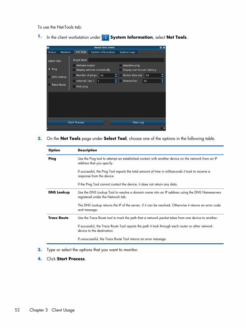
To use the Net-Tools tab:
1. In the client workstation under System Information, select Net Tools.
2. On the Net Tools page under Select Tool, choose one of the options in the following table.
Option Description
Ping Use the Ping tool to attempt an established contact with another device on the network from an IPaddress that you specify.
If successful, the Ping Tool reports the total amount of time in milliseconds it took to receive aresponse from the device.
If the Ping Tool cannot contact the device, it does not return any data.
DNS Lookup Use the DNS Lookup Tool to resolve a domain name into an IP address using the DNS Nameserversregistered under the Network tab.
The DNS Lookup returns the IP of the server, if it can be resolved. Otherwise it returns an error codeand message.
Trace Route Use the Trace Route tool to track the path that a network packet takes from one device to another.
If successful, the Trace Route Tool reports the path it took through each router or other networkdevice to the destination.
If unsuccessful, the Trace Route Tool returns an error message.
3. Type or select the options that you want to monitor.
4. Click Start Process.
52 Chapter 3 Client Usage
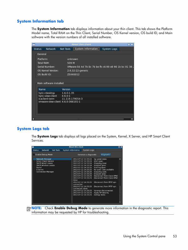
System Information tab
The System Information tab displays information about your thin client. This tab shows the PlatformModel name, Total RAM on the Thin Client, Serial Number, OS Kernel version, OS build ID, and Mainsoftware with the version numbers of all installed software.
System Logs tab
The System Logs tab displays all logs placed on the System, Kernel, X Server, and HP Smart ClientServices.
NOTE: Check Enable Debug Mode to generate more information in the diagnostic report. Thisinformation may be requested by HP for troubleshooting.
Using the System Control pane 53

Status icon
The fourth button displays an icon corresponding to the state of your smart client. Clicking on the iconwill give you a summary of the system state, and you can click the i button for further details.
● Error—a red X—There is a critical error such as lack of a network connection.
● Warning—a yellow triangle—There is a non-critical error such as inability to contact a SmartClient Service. Clicking on the icon clears the warning status.
● Busy—a spinning circle—The client is busy and no errors are present. This state is shown whennetworking is initializing, a connection is starting, etc.
● Idle—a question mark—The client is idle and no errors are present. Click on the icon to learn thestatus of the system.
● Updating—spinning arrows—The client is currently receiving or installing an update from HPSmart Client Services.
USB boot● Download image off web on page 54
● Reimage device on page 54
Download image off web
If the device beeps two times after it is powered on or does not appear to boot, then the devicefirmware may be corrupt. It is possible to recover from this by downloading the Smart Client reimagingtool from HP.com, installing the tools on a removable USB flash drive, and then booting the device fromthe USB flash drive.
Reimage device
1. Download the image from the web.
2. Unpack the image to C:\USBBoot.
3. Format a USB flash drive.
4. Copy all files from C:\USBBoot into the root of the USB flash drive device.
5. Power off the thin client.
6. Insert the USB flash drive into the thin client.
7. Turn on the thin client.
8. The thin client will boot to the USB flash drive at this point.
9. Follow the menu to re-image the thin client.
10. Select the image you unloaded from the web in step 1.
54 Chapter 3 Client Usage

11. Type Yes and press Enter to proceed.
12. When the reimage process is finished, remove the USB flash drive and press Enter.
Retrieving System Diagnostics● What is System Diagnostics? on page 55
● Saving System Diagnostics on page 55
● Opening System Diagnostics on page 56
● What to look for in System Diagnostics on page 57
What is System Diagnostics?
System Diagnostics takes a 'snapshot' of the thin client that can be used to help solve issues withouthaving to be in front of the thin client itself. This snapshot contains log files from BIOS information to theprocesses active at the time the System Diagnostics were run.
NOTE: Check Enable Debug Mode to generate more information in the diagnostic report. Thisinformation may be requested by HP for troubleshooting.
Because the system resets logs files when it reboots, it is important to capture logs before a reboot.
Saving System Diagnostics
1. Insert a USB flash memory device into the thin client
2. Next:
On ThinPro
a. On the Control Panel, click System Information.
b. Click the Net Tools tab.
On the Zero Client login dialog
a. Under the icon on the Zero Client login dialog, click System Information.
b. Click the System Logs tab.
Retrieving System Diagnostics 55
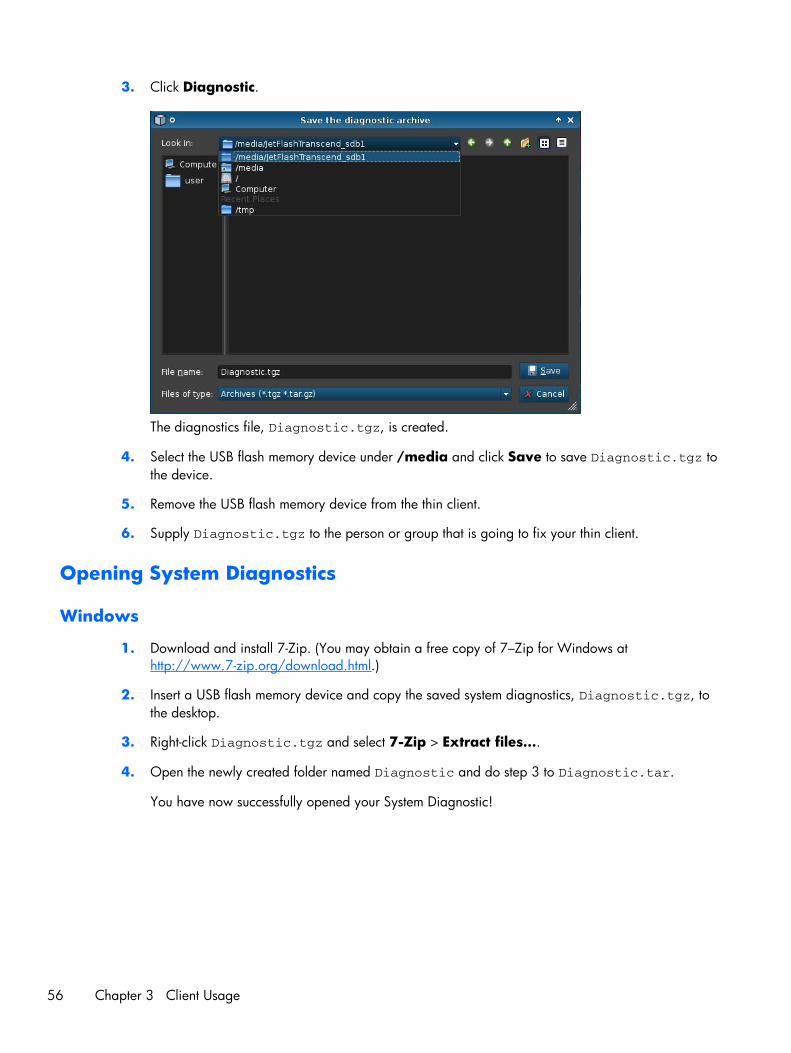
3. Click Diagnostic.
The diagnostics file, Diagnostic.tgz, is created.
4. Select the USB flash memory device under /media and click Save to save Diagnostic.tgz tothe device.
5. Remove the USB flash memory device from the thin client.
6. Supply Diagnostic.tgz to the person or group that is going to fix your thin client.
Opening System Diagnostics
Windows
1. Download and install 7-Zip. (You may obtain a free copy of 7–Zip for Windows athttp://www.7-zip.org/download.html.)
2. Insert a USB flash memory device and copy the saved system diagnostics, Diagnostic.tgz, tothe desktop.
3. Right-click Diagnostic.tgz and select 7-Zip > Extract files….
4. Open the newly created folder named Diagnostic and do step 3 to Diagnostic.tar.
You have now successfully opened your System Diagnostic!
56 Chapter 3 Client Usage

Linux/Unix
1. Insert a USB flash memory device and copy the saved system diagnostics, Diagnostic.tgz, tothe home directory.
2. Open a terminal and browse to the home directory.
3. Type tar xvfz Diagnostic.tgz in the command line.
You have now successfully opened your System Diagnostic!
What to look for in System Diagnostics
● The commands folder contains files such as:
◦ dmidecode.txt with information on the BIOS and graphics
◦ dpkg_--list.txt with a list of the current packages installed at the time SystemDiagnostics was run
◦ ps_-ef.txt with a list of the current processes at the time at the time System Diagnosticswas run
● The files/var/log folder contains useful log files such as:
◦ Xorg.0.log, which contains information on graphics, mouse, and keyboard
◦ kern.log, which contains information on the kernel
● The files/etc folder contains the current file system at time System Diagnostics was run.
Retrieving System Diagnostics 57