hp pavilion 14 notebook pc hp pavilion touchsmart …h10032. warning notice warning! to reduce the...
TRANSCRIPT
HP Pavilion 14 Notebook PCHP Pavilion TouchSmart 14 Notebook PC
Maintenance and Service Guide

© Copyright 2013, 2014 Hewlett-PackardDevelopment Company, L.P.
AMD and AMD Radeon are trademarks ofAdvanced Micro Devices, Inc. Bluetooth is atrademark owned by its proprietor and usedby Hewlett-Packard Company under license.Intel, Pentium, and Core are trademarks ofIntel Corporation in the U.S. and othercountries. Microsoft and Windows are U.S.registered trademarks of MicrosoftCorporation.
Product notice
This guide describes features that arecommon to most models. Some features maynot be available on your computer.
Not all features are available in all editionsof Windows 8. This computer may requireupgraded and/or separately purchasedhardware, drivers and/or software to takefull advantage of Windows 8 functionality.See http://www.microsoft.com for details.
The information contained herein is subjectto change without notice. The onlywarranties for HP products and services areset forth in the express warranty statementsaccompanying such products and services.Nothing herein should be construed asconstituting an additional warranty. HP shallnot be liable for technical or editorial errorsor omissions contained herein.
Second Edition: August 2014
First Edition: September 2013
Document Part Number: 730398-002

Important Notice about Customer Self-Repair Parts
CAUTION: Your computer includes Customer Self-Repair parts and parts that should only beaccessed by an authorized service provider. See Chapter 5, "Removal and replacement procedures forCustomer Self-Repair parts," for details. Accessing parts described in Chapter 6, "Removal andreplacement procedures for Authorized Service Provider only parts," can damage the computer or voidyour warranty.
iii

iv Important Notice about Customer Self-Repair Parts

Safety warning notice
WARNING! To reduce the possibility of heat-related injuries or of overheating the device, do notplace the device directly on your lap or obstruct the device air vents. Use the device only on a hard, flatsurface. Do not allow another hard surface, such as an adjoining optional printer, or a soft surface,such as pillows or rugs or clothing, to block airflow. Also, do not allow the AC adapter to contact theskin or a soft surface, such as pillows or rugs or clothing, during operation. The device and the ACadapter comply with the user-accessible surface temperature limits defined by the InternationalStandard for Safety of Information Technology Equipment (IEC 60950).
v

vi Safety warning notice

Table of contents
1 Product description ........................................................................................................... 1
2 External component identification ..................................................................................... 7
Finding your hardware and software information ......................................................................... 7Locating hardware .................................................................................................... 7Locating software ...................................................................................................... 7
Right side ................................................................................................................................ 8Left side ................................................................................................................................ 10Display ................................................................................................................................. 12Top ...................................................................................................................................... 13
TouchPad ............................................................................................................... 13Lights ..................................................................................................................... 14Buttons and speakers ............................................................................................... 15Keys ...................................................................................................................... 16
Bottom .................................................................................................................................. 17Labels ................................................................................................................................... 19
3 Illustrated parts catalog .................................................................................................. 21
Computer major components ................................................................................................... 21Display assembly subcomponents ............................................................................................. 30Miscellaneous parts ................................................................................................................ 31Mass storage devices ............................................................................................................. 33Sequential part number listing .................................................................................................. 34
4 Removal and replacement procedures preliminary requirements .................................... 43
Tools required ....................................................................................................................... 43Service considerations ............................................................................................................ 43
Plastic parts ............................................................................................................ 43Cables and connectors ............................................................................................ 44Drive handling ........................................................................................................ 44
Grounding guidelines ............................................................................................................. 45
vii

Electrostatic discharge damage ................................................................................. 45Packaging and transporting guidelines ....................................................... 46Workstation guidelines ............................................................................. 46Equipment guidelines ................................................................................ 47
5 Removal and replacement procedures for Customer Self-Repair parts ............................. 48
Component replacement procedures ........................................................................................ 48Battery ................................................................................................................... 49Service door ........................................................................................................... 50Memory module ...................................................................................................... 51WLAN module ........................................................................................................ 53Optical drive .......................................................................................................... 55
6 Removal and replacement procedures for Authorized Service Provider parts .................. 58
Component replacement procedures ........................................................................................ 58Display panel ......................................................................................................... 59Keyboard ............................................................................................................... 62Top cover ............................................................................................................... 67Hard drive ............................................................................................................. 71Power button board ................................................................................................. 75TouchPad button board ............................................................................................ 77Optical drive connector cable ................................................................................... 78System board ......................................................................................................... 80RTC battery ............................................................................................................ 87Fan ....................................................................................................................... 89Heat sink assembly .................................................................................................. 91Power connector cable ............................................................................................ 95Speakers ................................................................................................................ 97Display assembly .................................................................................................... 98Display assembly subcomponents ............................................................................ 101
7 Windows 8 – Using Setup Utility (BIOS) and HP PC Hardware Diagnostics (UEFI) ........... 105
Starting Setup Utility (BIOS) ................................................................................................... 105Updating the BIOS ............................................................................................................... 105
Determining the BIOS version ................................................................................. 105Downloading a BIOS update .................................................................................. 106
Using HP PC Hardware Diagnostics (UEFI) .............................................................................. 107Downloading HP PC Hardware Diagnostics (UEFI) to a USB device ............................. 107
viii

8 Ubuntu Linux – Using Setup Utility (BIOS) and System Diagnostics ................................. 108
Starting Setup Utility ............................................................................................................. 108Using Setup Utility ................................................................................................................ 108
Changing the language of Setup Utility .................................................................... 108Navigating and selecting in Setup Utility .................................................................. 109Displaying system information ................................................................................. 109Restoring factory default settings in Setup Utility ........................................................ 109Exiting Setup Utility ............................................................................................... 109
Updating the BIOS ............................................................................................................... 110Determining the BIOS version ................................................................................. 110Downloading a BIOS update .................................................................................. 110
Using Advanced System Diagnostics ...................................................................................... 111
9 Specifications ................................................................................................................ 112
Computer specifications ........................................................................................................ 11235.56 cm (14.0 in), display specifications .............................................................................. 113Hard drive specifications ...................................................................................................... 114DVD±RW SuperMulti Double-Layer Combination Drive specifications ......................................... 115
10 Windows 8 – Backing up, restoring, and recovering ................................................... 116
Creating recovery media and backups ................................................................................... 117Creating HP Recovery media .................................................................................. 117
Restore and recovery ............................................................................................................ 119Recovering using HP Recovery Manager .................................................................. 119
What you need to know .......................................................................... 120Using the HP Recovery partition to recover a minimized image .................... 120Using HP Recovery media to recover ........................................................ 121Changing the computer boot order ........................................................... 121
Removing the HP Recovery partition ........................................................................ 121
11 Ubuntu Linux – Backing up, restoring, and recovering ................................................ 122
Performing a system recovery ................................................................................................ 122Creating the restore DVDs ...................................................................................... 122Creating a restore image on a USB device ............................................................... 123Performing recovery using the restore media ............................................................. 123
Backing up your information .................................................................................................. 124
12 Power cord set requirements ...................................................................................... 125
Requirements for all countries ................................................................................................ 125Requirements for specific countries and regions ....................................................................... 126
ix

13 Recycling .................................................................................................................... 128
Index ............................................................................................................................... 129
x

1 Product description
Category Description AMD Intel
ProductName
HP Pavilion 14 Notebook PC
HP Pavilion TouchSmart 14 Notebook PC
√ √
Processors Processors are attached to the system board.
AMD™ ● AMD A10-5745M (2.9 GHz/2.1 GHz, 4 MB L2, 1333 MHzDDR3L) quad core, 25 W
● AMD A8-5545M (2.7 GHz/1.7 GHz, 4 MB L2, 1333 MHzDDR3L) quad core, 19 W
● AMD A8-4555M (2.4 GHz/1.6 GHz, 4 MB L2, 1333 MHzDDR3L) quad core, 19 W, for use with computer models with UMAgraphics
● AMD A6-4455M (2.6 GHz/2.1 GHz, 2MB L2, 1333 MHz DDR3L)dual core, 17 W, for use with computer models with UMA graphics
● AMD A6-5200 (2.0 GHz, 2 MB L2, 1600 MHz DDR3L), quadcore, 25 W
● AMD A4-5000 (1.5 GHz, 2 MB L2, 1600 MHz DDR3L), quadcore, 15 W
● AMD E2-3000 (1.65 GHz, 1 MB L2, 1600 MHz DDR3L), dualcore, 15 W
√
Intel® 4th generation processors:
● Intel CoreTM i7-4500U 1.8 GHz processor (3.0 MB L3 cache,15 W)
● Intel Core i5-4200U 1.6 GHz processor (3.0 MB L3 cache, 15 W)
● Intel Core i3-4005U 1.7 GHz processor (3.0 MB L3 cache, 15 W)
3rd generation processors:
● Intel Core i3-3217U 1.8 GHz processor (3.0 MB L3 cache, 1600MHz DDR3, 17 W)
● Intel Pentium 2117U 1.8 GHz processor (2.0 MB L3 cache, 1600MHz DDR3, 17 W)
√
1

Category Description AMD Intel
Chipset ● AMD A76M FCH √
● Intel HM76 Express (for use with 4th generation Intel processors)
● Intel HM86 Express (Integrated in MCP), for use with 3rd generationIntel processors
√
Category Description AMD Intel
Graphics Internal graphics:
● AMD Radeon HD 8610G, for use with computer models withA10-5745M processor
● AMD Radeon HD 8510G, for use with computer models withA8-5545M processor
● AMD Radeon HD 8400G, for use with computer models withA6-5200 processor
● AMD Radeon HD 8330, for use with computer models with A4-5000processor
● AMD Radeon HD 8280, for use with computer models with E2-3000processor
● AMD Radeon HD 7600G, for use with computer models withA8-4555M processor
● AMD Radeon HD 7500G, for use with computer models withA6-4455M processor
√
● Intel HD Graphics 4400, for use with 4th Generation Intel Coreprocessors
● Intel HD Graphics 4000, for use with 3rd Generation Intel Coreprocessors
● Intel HD Graphics, for use with 3rd Generation Intel Pentiumprocessors
√
Switchable discrete graphics:
Supports:
HD decode, DX11.1, and HDMI
Px5.5
√ √
2 Chapter 1 Product description

Category Description AMD Intel
HD decode, DX11, and HDMI
AMD Start Now (AMD IOIC) 1.0
AMD Start Now (AMD IOIC) 2.0
√
Optimus, supports Dynamic Switching √
● AMD Radeon™ HD 8670M with 2048 MB of dedicated videomemory (256 M x 16 DDR3 1 GHz x 4 PCs)
● AMD Radeon HD 8670M with 1024 MB of dedicated video memory(128 M x16 DDR3 1 GHz x 4 PCs)
√ √
● NVIDIA GeForce GT 740M with 2048 MB of dedicated videomemory (258 M x 16 DDR3 900 MHz x 4 PCs), 64 bit
√
Dual Graphics:
● AMD Radeon HD 8610G + HD 8670M Dual Graphics, for use withcomputer models with A10-5745M processors
● AMD Radeon HD 8510G + HD 8670M Dual Graphics, for use withcomputer models with A8-5545M processors
√
Panel ● 35.56 cm (14 in), high-definition (HD), white light-emitting diode(WLED), BrightView (1366×768) flat display, 3.6 mm, SVA, typicalbrightness: 200 cd/m2 (nits)
● 35.56 cm (14 in), HD, WLED, BrightView (1366×768) slim display,3.0 mm, typical brightness: 200 cd/m2 (nits) SVA + eTP touch(Multitouch enabled)
16:9 Ultra Wide Aspect Ratio
√ √
Memory Supports the following configurations:
● 12288 MB (8192 MB×1+ 4096 MB×1) (select models only)
● 8192 MB (8192 MB×1 or 4096 MB×2; not supported on computermodels equipped with a 32-bit operating system)
● 6144 MB (4096 MB×1 + 2048 MB×1; not supported on computermodels equipped with a 32-bit operating system)
● 4096 MB (4096 MB×1 or 2048 MB×2)
● 2048 MB (2048 MB×1)
Two SODIMM customer-accessible/upgradable memory module slots
DDR3L-1600 MHz dual channel support
√ √
DDR3L-1600 MHz single channel support √
3

Category Description AMD Intel
Hard drive Supports 6.35 cm (2.5 in) hard drives in 9.5 mm (.37 in) and 7.0 mm(.28 in) thicknesses (all hard drives use the same bracket)
Supports the following hard drives:
● 1 TB, 5400 rpm, 9.5 mm
● 750 GB, 5400 rpm, 9.5 mm
● 500 GB, 5400 rpm, 7.0 mm
Customer-accessible
Serial ATA
HP 3D DriveGuard
√ √
24 GB mSATA solid-state drive with system memory up to 8 GB (for usewith select computer models with switchable discrete graphics)
√
Supports the following:
● 500 GB, 5400 rpm, + 8 GB NAND Hybrid HDD; 7 mm
● 750 GB, 5400 rpm, + 8 GB NAND Hybrid HDD; 9.5 mm
● 1 TB, 5400 rpm, + 8 GB NAND Hybrid HDD; 9.5 mm
√
Optical drive Fixed
Serial ATA
9.5 mm tray load
DVD±RW Double-Layer SuperMulti Drive
Zero power optical drive
√ √
Audioand video
Supports:
DTS Sound+
Dual speakers
HP TrueVision HD webcam (fixed, no tilt with activity LED; 1280×720 by30 frames per second)
Two dual array, digital microphones with appropriate beam-forming, echo-cancellation, noise-reduction software
USB 2.0, M-jpeg
√ √
Supports Nuance Voice Recognition √
Ethernet Integrated 10/100 NIC √ √
Wireless Integrated wireless local area network (WLAN) options by way of wirelessmodule
One half-size mini card slot
Two WLAN antennas built into display assembly
√ √
4 Chapter 1 Product description

Category Description AMD Intel
Support for the following WLAN formats:
● Qualcomm Atheros AR9485 802.11 bgn 1x1 Wi-Fi Adapter
● Ralink RT3290LE 802.11 bgn 1x1 Wi-Fi + Bluetooth 4.0 ComboAdapter
● Realtek RTL8188EE 802.11 bgn 1x1 Wi-Fi Adapter
√ √
● Intel Wireless-N 7260BN 802.11 bgn 2x2 Wi-Fi + Bluetooth 4.0combo adapter WLAN module; Intel WiDi support. Support for IntelSmart Connect Technology 4.1. No support for Ubuntu Linux.
● Mediatek MT7630E 802.11 bgn 1x1 Wi-Fi + Bluetooth 4.0 ComboAdapter
√
Externalmedia cards
HP Multi-Format Memory Card Reader slot with push-push technology,supporting the following digital card formats:
● Secure Digital (SD) Memory Card
● Secure Digital High Capacity (SDHC) Memory Card
● Secure Digital eXtended Capacity (SDXC) Memory Card
√ √
Ports ● AC Smart Pin adapter plug (4.5 mm barrel)
● Combination audio-out (stereo headphone)/audio-in (monomicrophone)
● RJ-45 (Ethernet)
● USB 3.0 (2 ports), USB 2.0 (1 port)
√ √
● HDMI version 1.4 output supporting 1920 x 1080 @ 60 Hz HotPlug / Unplug and auto detect for correct output to wide-aspect versusstandard aspect video
√
● HDMI version 1.4 output supporting 1920 x 1200 @ 60 Hz HotPlug / Unplug and auto detect for correct output to wide-aspect versusstandard aspect video
√
Keyboard/pointingdevices
Full-size black textured island-style, with black keyboard frame
Full-size white painted island-style, with white keyboard frame
Multitouch gestures enabled
Supports Windows 8 Modern Trackpad Gestures
Supports PS/2 interface
√ √
Powerrequirements
Supports the following AC adapters:
● 65 W HP Smart AC adapter (nPFC, 3-wire, 4.5 mm)
√ √
● 90 W Smart AC adapter (PFC, 3-wire, 4.5 mm) √
5

Category Description AMD Intel
Supports battery fast charge
Supports the following batteries (battery is user-removable)
● 4 cell battery - 41 Whr (2.8 AH)
√ √
● 4 cell battery - 48 Whr (3.2 AH) √
Security ● Security cable lock √ √
● Intel IPT support
● Intel AT-p Ready support (select models only)
√
Operatingsystem
Preinstalled:
● Windows 8 Standard 64-bit
● Windows 8 Professional 64-bit
● FreeDOS 2.0
● Ubuntu Linux
√ √
Serviceability End-user replaceable parts:
● AC adapter
● Battery
● Keyboard (select model replacement only)
● Memory module
● Optical drive
● WLAN module
√ √
6 Chapter 1 Product description

2 External component identification
Finding your hardware and software information
Locating hardware
To find out what hardware is installed on your computer:
1. From the Start screen, type c, and then select Control Panel.
2. Select System and Security, and then in the System area, click Device Manager.
A list reveals all the devices installed on your computer.
Locating software
To find out what software is installed on your computer:
1. From the Start screen, right-click using the mouse.
– or –
Swipe from the top of the TouchPad to reveal all apps.
2. Select the All apps icon.
Finding your hardware and software information 7

Right side
Component Description
(1) Power light ● On: The computer is on.
● Blinking: The computer is in the Sleep state, a power-savingstate. The computer shuts off power to the display and otherunneeded components.
● Off: The computer is off or in Hibernation. Hibernation is apower-saving state that uses the least amount of power.
NOTE: For select models, the Intel Rapid Start Technologyfeature is enabled at the factory. Rapid Start Technologyallows your computer to resume quickly from inactivity.
(2) Hard drive light ● Blinking white: The hard drive is being accessed.
● Amber: HP 3D DriveGuard has temporarily parked the harddrive.
(3) Audio-out (headphone) / Audio-in(microphone) jack
Connects optional powered stereo speakers, headphones,earbuds, a headset, or a television audio cable. Also connects anoptional headset microphone. This jack does not support optionalmicrophone-only devices.
WARNING! To reduce the risk of personal injury, adjust thevolume before using the headphones, earbuds, or a headset. Foradditional safety information, refer to the Regulatory, Safety andEnvironmental Notices. To access this guide, from the Start screen,type support, select the HP Support Assistant app, selectMy computer, and then select User guides.
NOTE: When a device is connected to the jack, the computerspeakers are disabled.
NOTE: Be sure that the device cable has a 4-conductorconnector that supports both audio-out (headphone) and audio-in(microphone).
(4) USB 2.0 port Connects an optional USB device, such as a keyboard, mouse,external drive, printer, scanner, or USB hub.
8 Chapter 2 External component identification

Component Description
(5) Optical drive Reads and/or writes, depending on your computer model, to anoptical disc.
NOTE: For disc compatibility information, navigate to the Helpand Support webpage. Follow the web page instructions to selectyour computer model. Select Support & Drivers, and then selectProduct Information.
(6) Optical drive eject button Releases the disc tray.
Right side 9

Left side
Component Description
(1) Power connector Connects an AC adapter.
(2) AC adapter light ● White: The AC adapter is connected and the battery ischarged.
● Amber: The AC adapter is connected and the battery ischarging.
● Off: The computer is using DC power.
(3) Security cable slot Attaches an optional security cable to the computer.
NOTE: The security cable is designed to act as adeterrent, but it may not prevent the computer from beingmishandled or stolen.
(4) RJ-45 (network) jack
RJ-45 (network) status lights (2)
Connects a network cable.
White: The network is connected.
Amber: Activity is occurring on the network.
(5) Vent Enable airflow to cool internal components.
NOTE: The computer fan starts up automatically to coolinternal components and prevent overheating. It is normal forthe internal fan to cycle on and off during routine operation.
(6) HDMI port Connects an optional video or audio device, such as a high-definition television, any compatible digital or audiocomponent, or a high-speed HDMI device.
10 Chapter 2 External component identification

Component Description
(7) USB 3.0 ports (2) Connect optional USB device, such as a keyboard, mouse,external drive, printer, scanner or USB hub.
(8) Memory card reader Reads data from and writes data to memory cards such asSecure Digital (SD).
To insert:
1. Hold the card, label side up, with connectors facing theslot and push in the card until it is firmly seated.
To remove:
1. Press in on the card and quickly release it until it popsout.
Left side 11

Display
Component Description
(1) WLAN antennas (2)* Send and receive wireless signals to communicate with wirelesslocal area networks (WLANs).
NOTE: To set up a WLAN and connect to the Internet, youneed a broadband modem (either DSL or cable) (purchasedseparately), high-speed internet service purchased from anInternet service provider, and a wireless router (purchasedseparately).
(2) Internal microphones (2) Record sound.
(3) Webcam light On: The webcam is in use.
(4) Webcam Records video and captures photographs. Some models mayallow you to video conference and chat online using streamingvideo.
To use the webcam, from the Start screen, type c, and then selectCyberLink YouCam from the list of applications.
*The antennas are not visible from the outside of the computer. For optimal transmission, keep the areas immediately aroundthe antennas free from obstructions. For wireless regulatory notices, see the section of the Regulatory, Safety, andEnvironmental Notices that applies to your country or region. To access this guide, from the Start screen, type support, selectthe HP Support Assistant app, select My computer, and then select User guides.
12 Chapter 2 External component identification

Top
TouchPad
Component Description
(1) TouchPad zone Moves the on-screen pointer and selects or activates items onthe screen.
NOTE: The TouchPad also supports edge-swipe gestures.
(2) Left TouchPad button Functions like the left button on an external mouse.
(3) Right TouchPad button Functions like the right button on an external mouse.
Top 13

Lights
Component Description
(1) Power light ● On: The computer is on.
● Blinking: The computer is in the Sleep state, a power-saving state. The computer shuts off power to thedisplay and other unneeded components.
● Off: The computer is off or in Hibernation. Hibernationis a power-saving state that uses the least amount ofpower.
NOTE: For select models, the Intel Rapid StartTechnology feature is enabled at the factory. Rapid StartTechnology allows your computer to resume quicklyfrom inactivity.
(2) Caps lock light On: Caps lock is on, which switches the keys to all capitalletters.
(3) Mute light ● Amber: Computer sound is off.
● Off: Computer sound is on.
(4) Wireless light On: An integrated wireless device, such as a wireless localarea network (WLAN) device and/or a Bluetooth® device, ison.
NOTE: On some models, the wireless light is amber whenall wireless devices are off.
14 Chapter 2 External component identification

Buttons and speakers
Component Description
(1) Power button ● When the computer is off, press the button to turn onthe computer.
● When the computer is on, press the button briefly toinitiate Sleep.
● When the computer is in the Sleep state, press thebutton briefly to exit Sleep.
● When the computer is in Hibernation, press the buttonbriefly to exit Hibernation.
CAUTION: Pressing and holding down the power buttonwill result in the loss of unsaved information.
If the computer has stopped responding and Windows®shutdown procedures are ineffective, press and hold thepower button down for at least 5 seconds to turn off thecomputer.
NOTE: For select models, the Intel Rapid Start Technologyfeature is enabled at the factory. Rapid Start Technologyallows your computer to resume quickly from inactivity.
To learn more about your power settings, see your poweroptions. From the Start screen, type power, select Settings,and then select Power Options from the list ofapplications.
(2) Speakers (2) Produce sound.
Top 15

Keys
Component Description
(1) esc key Reveals system information when pressed in combinationwith the fn key.
(2) fn key Executes frequently used system functions when pressed incombination with the esc key.
(3) Windows key Returns you to the Start screen from an open app or theWindows desktop.
NOTE: Pressing the Windows key again will return you tothe previous screen.
(4) Action keys Execute frequently used system functions.
16 Chapter 2 External component identification

Bottom
Component Description
(1) Battery lock latch Unlocks the battery.
(2) Battery bay Holds the battery.
(3) Battery release latch Releases the battery from the battery bay, after the battery locklatch has been released.
Bottom 17

Component Description
(4) Vents (8) Enable airflow to cool internal components.
NOTE: The computer fan starts up automatically to cool internalcomponents and prevent overheating. It is normal for the internalfan to cycle on and off during routine operation.
(5) Service door Provides access to the wireless LAN (WLAN) module slot and thememory module slots.
CAUTION: To prevent an unresponsive system, replace thewireless module only with a wireless module authorized for use inthe computer by the governmental agency that regulates wirelessdevices in your country or region. If you replace the module andthen receive a warning message, remove the module to restorecomputer functionality, and then contact support through Helpand Support. From the Start screen, type h, and then select Helpand Support.
18 Chapter 2 External component identification

LabelsThe labels affixed to the computer provide information you may need when you troubleshoot systemproblems or travel internationally with the computer.
IMPORTANT: All labels described in this section will be located in one of 3 places depending onyour computer model: Affixed to the bottom of the computer, located in the battery bay, or under theservice door.
For help finding these locations, refer to Bottom on page 17.
● Service label—Provides important information to identify your computer. When contacting support,you will probably be asked for the serial number, and possibly for the product number or themodel number. Locate these numbers before you contact support.
NOTE: Your service labels will resemble one of the examples shown below. Refer to theillustration that most closely matches the service label on your computer.
Component
(1) Product name
(2) Serial number
(3) Product number
(4) Warranty period
(5) Model number (select models only)
Component
(1) Serial number
(2) Product number
(3) Warranty period
Labels 19

Component
(4) Model number (select models only)
(5) Revision number
● Regulatory label(s)—Provide(s) regulatory information about the computer.
● Wireless certification label(s)—Provide(s) information about optional wireless devices and theapproval markings for the countries or regions in which the devices have been approved for use.
20 Chapter 2 External component identification

3 Illustrated parts catalog
Computer major componentsNOTE: HP continually improves and changes product parts. For complete and current information onsupported parts for your computer, go to http://partsurfer.hp.com, select your country or region, andthen follow the on-screen instructions.
NOTE: Details about your computer, including model, serial number, product key, and length ofwarranty, are on the service tag at the bottom of your computer. See Labels on page 19 for details.
Computer major components 21

22 Chapter 3 Illustrated parts catalog
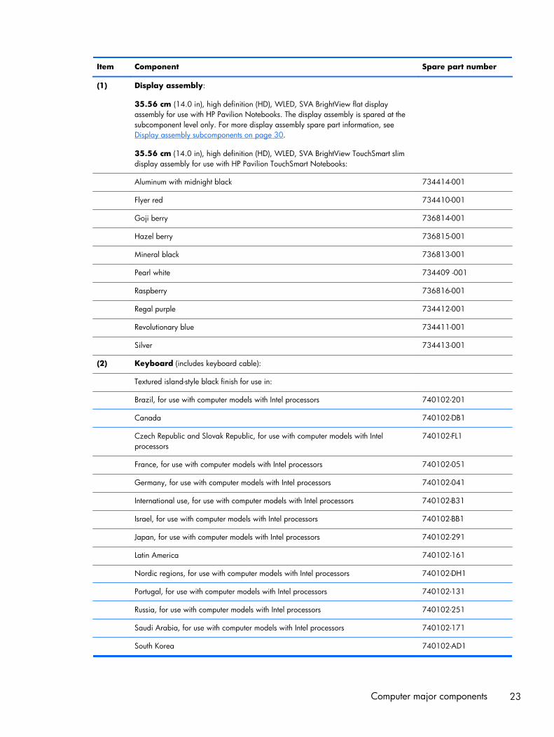
Item Component Spare part number
(1) Display assembly:
35.56 cm (14.0 in), high definition (HD), WLED, SVA BrightView flat displayassembly for use with HP Pavilion Notebooks. The display assembly is spared at thesubcomponent level only. For more display assembly spare part information, seeDisplay assembly subcomponents on page 30.
35.56 cm (14.0 in), high definition (HD), WLED, SVA BrightView TouchSmart slimdisplay assembly for use with HP Pavilion TouchSmart Notebooks:
Aluminum with midnight black 734414-001
Flyer red 734410-001
Goji berry 736814-001
Hazel berry 736815-001
Mineral black 736813-001
Pearl white 734409 -001
Raspberry 736816-001
Regal purple 734412-001
Revolutionary blue 734411-001
Silver 734413-001
(2) Keyboard (includes keyboard cable):
Textured island-style black finish for use in:
Brazil, for use with computer models with Intel processors 740102-201
Canada 740102-DB1
Czech Republic and Slovak Republic, for use with computer models with Intelprocessors
740102-FL1
France, for use with computer models with Intel processors 740102-051
Germany, for use with computer models with Intel processors 740102-041
International use, for use with computer models with Intel processors 740102-B31
Israel, for use with computer models with Intel processors 740102-BB1
Japan, for use with computer models with Intel processors 740102-291
Latin America 740102-161
Nordic regions, for use with computer models with Intel processors 740102-DH1
Portugal, for use with computer models with Intel processors 740102-131
Russia, for use with computer models with Intel processors 740102-251
Saudi Arabia, for use with computer models with Intel processors 740102-171
South Korea 740102-AD1
Computer major components 23

Item Component Spare part number
Spain 740102-071
Switzerland, for use with computer models with Intel processors 740102-BG1
Taiwan 740102-AB1
Thailand 740102-281
Turkey, for use with computer models with Intel processors 740102-141
United Kingdom, for use with computer models with Intel processors 740102-031
United States 740102-001
Painted island-style white finish for use in:
Brazil, for use with computer models with Intel processors 740103-201
Canada 740103-DB1
Czech Republic and Slovak Republic, for use with computer models with Intelprocessors
740103-FL1
France, for use with computer models with Intel processors 740103-051
Germany, for use with computer models with Intel processors 740103-041
International use, for use with computer models with Intel processors 740103-B31
Israel, for use with computer models with Intel processors 740103-BB1
Latin America 740103-161
Nordic regions, for use with computer models with Intel processors 740103-DH1
Portugal, for use with computer models with Intel processors 740103-131
Russia, for use with computer models with Intel processors 740103-251
Saudi Arabia, for use with computer models with Intel processors 740103-171
South Korea 740103-AD1
Spain, for use with computer models with Intel processors 740103-071
Switzerland, for use with computer models with Intel processors 740103-BG1
Taiwan 740103-AB1
Thailand 740103-281
Turkey, for use with computer models with Intel processors 740103-141
United Kingdom, for use with computer models with Intel processors 740103-031
United States 740103-001
(3) Top cover (includes TouchPad and cable):
Aluminum with midnight black finish 734435-001
Flyer red finish 734431-001
Goji berry finish 736818-001
24 Chapter 3 Illustrated parts catalog

Item Component Spare part number
Hazel berry finish 736819-001
Mineral black finish 736817-001
Pearl white finish 734430-001
Raspberry finish 736820-001
Regal purple finish 734433-001
Revolutionary blue finish 734432-001
Sparkling black finish 734434-001
(4) Power button board (includes cable) 734416-001
(5) TouchPad button board (includes cable) 734418-001
(6) Power connector bracket is available with the power connector cable, spare part number 732067-001
(7) USB/audio board (includes cable) 734417-001
(8) Hard drive (does not include hard drive rubber bracket, hard drive connector cable, or screws):
1 TB, 5400 rpm, 9.5 mm 676521-005
750 GB, 5400 rpm, 9.5 mm 634250-005
500 GB, 5400 rpm, 7.0 mm 683802-005
mSATA solid-state drive, 24 GB (for use with select computer models with Intelprocessors, HM86 Express chipsets, and switchable discrete graphics)
732085-001
Hard Drive Hardware Kit (not illustrated, includes hard drive rubber bracket,hard drive connector cable, and screws)
740706-001
(9) System board (includes replacement thermal material):
For computer models equipped with Intel processors and UMA graphics
4th generation
Intel Core i5-4200U 1.6 GHz processor (3.0 MB L3 cache, 15 W) for use withFreeDOS and Ubuntu
734423-001
Intel Core i5-4200U 1.6 GHz processor (3.0 MB L3 cache, 15 W) for use withWindows Standard
734423-501
Intel Core i5-4200U 1.6 GHz processor (3.0 MB L3 cache, 15 W) for use withWindows Professional
734423-601
Intel Core i3-4005U 1.7 GHz processor (3.0 MB L3 cache, 15 W) for use withFreeDOS and Ubuntu
734424-001
Intel Core i3-4005U 1.7 GHz processor (3.0 MB L3 cache, 15 W) for use withWindows Standard
734424-501
Intel Core i3-4005U 1.7 GHz processor (3.0 MB L3 cache, 15 W) for use withWindows Professional
734424-601
For computer models equipped with Intel processors and UMA graphics
3rd generation
Computer major components 25

Item Component Spare part number
Intel HM76 chipset and Pentium 2117U HM76 (1.8 GHz, 2 MB L3 Cache, 1600MHz DDR3, 17 W) for use with FreeDOS and Ubuntu
738148-001
Intel HM76 chipset and Pentium 2117U HM76 (1.8 GHz, 2 MB L3 Cache, 1600MHz DDR3, 17 W) for use with Windows Standard
738148-501
Intel HM76 chipset and Pentium 2117U HM76 (1.8 GHz, 2 MB L3 Cache, 1600MHz DDR3, 17 W) for use with Windows Professional
738148-601
Intel HM76 chipset and Core i3-3217U (1.8 GHz, 3 MB L3 Cache, 1600 MHzDDR3, 17 W) for use with FreeDOS and Ubuntu
738150-001
Intel HM76 chipset and Core i3-3217U (1.8 GHz, 3 MB L3 Cache, 1600 MHzDDR3, 17 W) for use with Windows Standard
738150-501
Intel HM76 chipset and Core i3-3217U (1.8 GHz, 3 MB L3 Cache, 1600 MHzDDR3, 17 W) for use with Windows Professional
738150-601
For computer models equipped with Intel processors and discretegraphics
4th generation
NVIDIA N14P-GV2 GeForce GT 740M 2 GB graphics and Intel Core i7-4500U (1.8GHz DC 15 W) for use with FreeDOS and Ubuntu
738154-001
NVIDIA N14P-GV2 GeForce GT 740M 2 GB graphics and Intel Core i7-4500U (1.8GHz DC, 15 W) for use with Windows Standard
738154-501
NVIDIA N14P-GV2 GeForce GT 740M 2 GB graphics and Intel Core i7-4500U (1.8GHz DC, 15 W) for use with Windows Professional
738154-601
AMD Radeon 8670M 2 GB graphics and Intel Core i7-4500U (1.8 GHz DC, 15 W)for use with FreeDOS and Ubuntu
734429-001
AMD Radeon 8670M 2 GB graphics and Intel Core i7-4500U (1.8 GHz DC, 15 W)for use with Windows Standard
734429-501
AMD Radeon 8670M 2 GB graphics and Intel Core i7-4500U (1.8 GHz DC, 15 W)for use with Windows Professional
734429-601
NVIDIA N14P-GV2 GeForce GT 740M 2 GB graphics and Intel Core i5-4200U (1.6GHz DC, 15 W) for use with FreeDOS and Ubuntu
738156-001
NVIDIA N14P-GV2 GeForce GT 740M 2 GB graphics and Intel Core i5-4200U (1.6GHz DC, 15 W) for use with Windows Standard
738156-501
NVIDIA N14P-GV2 GeForce GT 740M 2 GB graphics and Intel Core i5-4200U (1.6GHz DC, 15 W) for use with Windows Professional
738156-601
AMD Radeon 8670M 2 GB graphics and Intel Core i5-4200U (1.6 GHz DC, 15 W)for use with FreeDOS and Ubuntu
734426-001
AMD Radeon 8670M 2 GB graphics and Intel Core i5-4200U (1.6 GHz DC, 15 W)for use with Windows Standard
734426-501
AMD Radeon 8670M 2 GB graphics and Intel Core i5-4200U (1.6 GHz DC, 15 W)for use with Windows Professional
734426-601
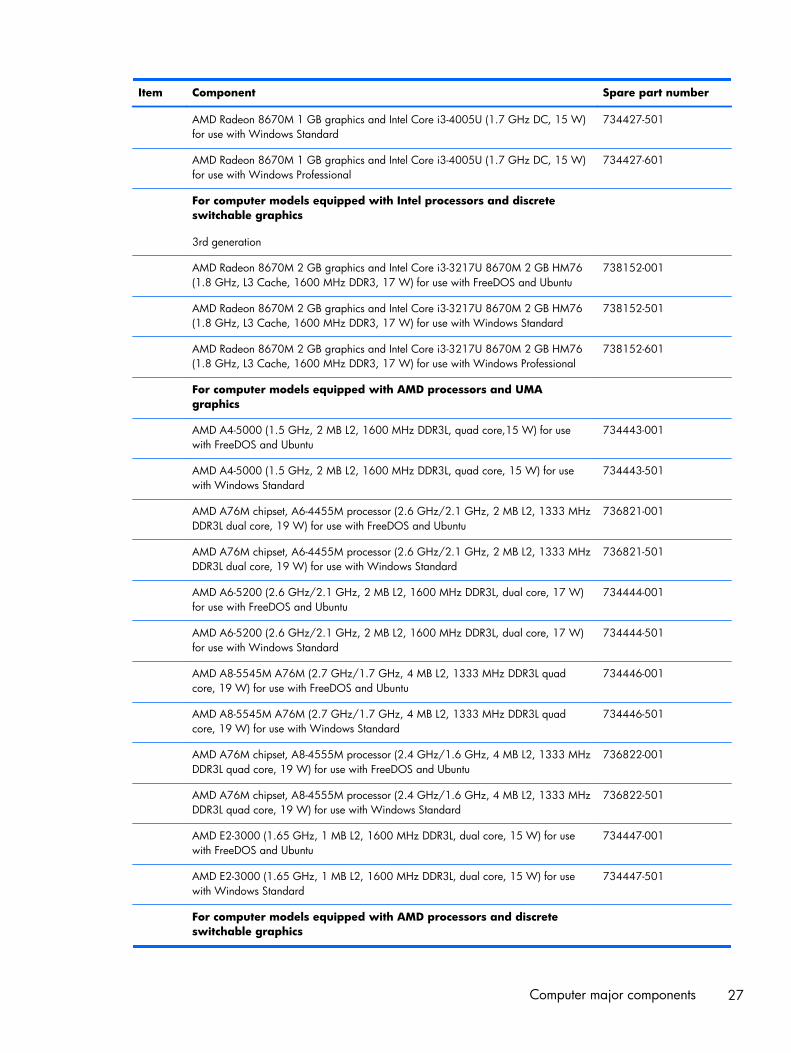
AMD Radeon 8670M 1 GB graphics and Intel Core i3-4005U (1.7 GHz DC, 15 W)for use with FreeDOS and Ubuntu
734427-001
26 Chapter 3 Illustrated parts catalog
Item Component Spare part number
AMD Radeon 8670M 1 GB graphics and Intel Core i3-4005U (1.7 GHz DC, 15 W)for use with Windows Standard
734427-501
AMD Radeon 8670M 1 GB graphics and Intel Core i3-4005U (1.7 GHz DC, 15 W)for use with Windows Professional
734427-601
For computer models equipped with Intel processors and discreteswitchable graphics
3rd generation
AMD Radeon 8670M 2 GB graphics and Intel Core i3-3217U 8670M 2 GB HM76(1.8 GHz, L3 Cache, 1600 MHz DDR3, 17 W) for use with FreeDOS and Ubuntu
738152-001
AMD Radeon 8670M 2 GB graphics and Intel Core i3-3217U 8670M 2 GB HM76(1.8 GHz, L3 Cache, 1600 MHz DDR3, 17 W) for use with Windows Standard
738152-501
AMD Radeon 8670M 2 GB graphics and Intel Core i3-3217U 8670M 2 GB HM76(1.8 GHz, L3 Cache, 1600 MHz DDR3, 17 W) for use with Windows Professional
738152-601
For computer models equipped with AMD processors and UMAgraphics
AMD A4-5000 (1.5 GHz, 2 MB L2, 1600 MHz DDR3L, quad core,15 W) for usewith FreeDOS and Ubuntu
734443-001
AMD A4-5000 (1.5 GHz, 2 MB L2, 1600 MHz DDR3L, quad core, 15 W) for usewith Windows Standard
734443-501
AMD A76M chipset, A6-4455M processor (2.6 GHz/2.1 GHz, 2 MB L2, 1333 MHzDDR3L dual core, 19 W) for use with FreeDOS and Ubuntu
736821-001
AMD A76M chipset, A6-4455M processor (2.6 GHz/2.1 GHz, 2 MB L2, 1333 MHzDDR3L dual core, 19 W) for use with Windows Standard
736821-501
AMD A6-5200 (2.6 GHz/2.1 GHz, 2 MB L2, 1600 MHz DDR3L, dual core, 17 W)for use with FreeDOS and Ubuntu
734444-001
AMD A6-5200 (2.6 GHz/2.1 GHz, 2 MB L2, 1600 MHz DDR3L, dual core, 17 W)for use with Windows Standard
734444-501
AMD A8-5545M A76M (2.7 GHz/1.7 GHz, 4 MB L2, 1333 MHz DDR3L quadcore, 19 W) for use with FreeDOS and Ubuntu
734446-001
AMD A8-5545M A76M (2.7 GHz/1.7 GHz, 4 MB L2, 1333 MHz DDR3L quadcore, 19 W) for use with Windows Standard
734446-501
AMD A76M chipset, A8-4555M processor (2.4 GHz/1.6 GHz, 4 MB L2, 1333 MHzDDR3L quad core, 19 W) for use with FreeDOS and Ubuntu
736822-001
AMD A76M chipset, A8-4555M processor (2.4 GHz/1.6 GHz, 4 MB L2, 1333 MHzDDR3L quad core, 19 W) for use with Windows Standard
736822-501
AMD E2-3000 (1.65 GHz, 1 MB L2, 1600 MHz DDR3L, dual core, 15 W) for usewith FreeDOS and Ubuntu
734447-001
AMD E2-3000 (1.65 GHz, 1 MB L2, 1600 MHz DDR3L, dual core, 15 W) for usewith Windows Standard
734447-501
For computer models equipped with AMD processors and discreteswitchable graphics
Computer major components 27

Item Component Spare part number
AMD Radeon 8670M 1 GB graphics A6-5200 processor (2.6 GHz/2.1 GHz, 2 MBL2, 1600 MHz DDR3L, dual core, 17 W) for use with FreeDOS and Ubuntu
734440-001
AMD Radeon 8670M 1 GB graphics A6-5200 processor (2.6 GHz/2.1 GHz, 2 MBL2, 1600 MHz DDR3L, dual core, 17 W) for use with Windows Standard
734440-501
AMD Radeon 8670M 2 GB graphics and A10-5745M processor (2.9 GHz/2.1GHz, 4 MB L2, 1333 MHz DDR3L quad core, 25 W) for use with FreeDOS andUbuntu
734441-001
AMD Radeon 8670M 2 GB graphics and A10-5745M processor (2.9 GHz/2.1GHz, 4 MB L2, 1333 MHz DDR3L quad core, 25 W) for use with Windows Standard
734441-501
(10) Fan 732068-001
(11) RTC battery 697917-001
(12) Heat sink assembly (includes replacement thermal material):
For use only on computer models equipped with Intel processors and switchablediscrete graphics
742582-001
For use only on computer models equipped with Intel processors and UMA graphics 742581-001
For use only on computer models equipped with Intel HM76 chipset and switchablediscrete graphics
742331-001
For use only on computer models equipped with Intel HM76 chipset andUMA graphics
742330-001
For use only on computer models equipped with AMD processors and UMA graphics19 W
734448-001
For use only on computer models equipped with AMD processors and UMA graphics25 W
734449-001
For use only on computer models equipped with AMD processors and switchablediscrete graphics 19 W
734450-001
For use only on computer models equipped with AMD processors and switchablediscrete graphics 25 W
734451-001
(13) Power connector cable (includes bracket): 732067-001
(14) Hard drive connector cable is available in the Hard Drive Hardware Kit, part number 740706-001
(15) Memory modules (2), (PC3L, 12800, 1600 MHz):
2 GB memory module 691739-001
4 GB memory module 691740-001
8 GB memory module 693374-001
(16) WLAN module:
Intel Wireless-N 7260BN 802.11 bgn 2x2 Wi-Fi + BT 4.0 combo adaptor for usewith computer models with Intel processors, not supported on Ubuntu
717384-001
Mediatek MT7630E 802.11 bgn Wi-Fi Adapter and Mediatek Bluetooth 4.0 Adapterfor use with computer models with Intel processors
710418-001
28 Chapter 3 Illustrated parts catalog

Item Component Spare part number
Qualcomm Atheros AR9485 802.11 bgn Wi-Fi Adapter 675794-001
Ralink RT3290LE 802.11 bgn 1×1 Wi-Fi and Bluetooth 4.0 Combo Adapter 690020-001
Realtek RTL8188EE 802.11 bgn Wi-Fi Adapter 709848-001
(17) Speakers (include subwoofer, speaker cables, and rubber isolators) 734422-001
(18) Battery
4 cell, 41 Whr, 2.8 Ah, Li-ion battery 728460-001
4 cell, 48 Whr, 3.2 Ah, Li-ion battery, for use with computer models with Intelprocessors
728461-001
(19) Base enclosure (includes battery release latch mechanism, RJ45 cover, and screws) 734406-001
(20) Optical drive, SuperMulti DVD±R/RW Double-Layer Drive (includes bezel, bracket,and screws)
734415-001
(21) Service door (part of the Plastics Kit 734419-001)
Computer major components 29

Display assembly subcomponentsNOTE: The display assembly subcomponents are for the HP Pavilion flat display models only. HPPavilion TouchSmart Notebooks are spared at the display assembly only.
Item Component Spare part number
(1) Display bezel (includes 2 rubber screws) 739355-001
(2) 35.56 cm (14 in), BrightView, HD, WLED, SVA flat display panel (Screwsincluded in the screw kit, spare part number 734421-001)
734420-001
(3) Webcamera/microphone module (includes adhesive and screws) 725665-001
(4) Display panel cable (includes webcamera/microphone module cable and screws) 734407-001
(5) Antenna Kit (includes left and right wireless antenna cables and transceivers and 2rubber screws)
734400-001
(6) Display Hinge Kit (includes left and right hinges and 2 rubber screws) 734408-001
(7) Display back cover (includes 2 rubber screws):
Aluminum with midnight black finish 734405-001
Flyer red finish 734401-001
Goji berry finish 736810-001
Hazel berry finish 736811-001
Mineral black finish 736809-001
Pearl white finish 726193-001
Raspberry finish 736812-001
30 Chapter 3 Illustrated parts catalog

Item Component Spare part number
Regal purple finish 734403-001
Revolutionary blue finish 734402-001
Silver finish 734404-001
Miscellaneous parts
Component Spare part number
AC adapter:
45 W HP Smart AC adapter (nPFC, RC, 3-wire, 4.5 mm)
65 W HP Smart AC adapter (nPFC, RC, 3-wire, 4.5 mm), select models only 714657-001
65 W HP Smart AC adapter (nPFC, RC, 3-wire, 4.5 mm) 710412-001
90 W HP Smart AC adapter (PFC, RC, 3-wire, 4.5 mm), for use with computer models with AMDprocessors
710413-001
90 W HP Smart AC adapter (PFC, RC, 3-wire, 4.5 mm), for use with computer models with AMDprocessors, select models only
710414-001
Power cord (3 pin, black, 1.83 m):
For use in the United States 490371-001
For use in Argentina 490371-D01
For use in Australia, for use with computer models with Intel processors 490371-011
For use in Brazil 490371-202
For use in Denmark, for use with computer models with Intel processors 490371-081
For use in Europe 490371-021
For use in India 490371-D61
For use in Israel, for use with computer models with Intel processors 490371-BB1
For use in Italy 490371-061
For use in Japan, for use with computer models with Intel processors 490371-291
For use in the People's Republic of China 490371-AA1
For use in South Africa, for use with computer models with Intel processors 490371-AR1
For use in South Korea 490371-AD1
For use in Switzerland, for use with computer models with Intel processors 490371-111
For use in Taiwan 490371-AB1
For use in Thailand 490371-201
Miscellaneous parts 31

Component Spare part number
For use in the United Kingdom and Singapore 490371-031
Screw Kit 734421-001
HDMI to VGA Adapter for use with computer models with AMD processors 701943-001
32 Chapter 3 Illustrated parts catalog

Mass storage devices
Item Component Spare part number
(1) Hard drive (does not include the hard drive rubber bracket, hard drive connector cable, or screws)
1 TB, 5400 rpm, 9.5 mm 676521-005
750 GB, 5400 rpm, 9.5 mm 634250-005
500 GB 5400 rpm 7 mm 683802-005
mSATA solid-state drive, 24 GB (for use with select computer models with Intelprocessors, HM86 Express chipsets, and switchable discrete graphics)
732085-001
Hard Drive Hardware Kit, includes: 740706-001
Hard drive rubber bracket
Hard drive connector cable
Hard drive screws
(3) Optical drive:
DVD+/-RW DL SuperMulti -- support Zero power ODD (includes optical drive hardwarekit with optical drive bezel, bracket and connector cable).
734415-001
Mass storage devices 33

Sequential part number listing
Spare part number Description
490371-001 Power cord for use in North America (3 pin, black, 1.83 m)
490371-011 Power cord for use in Australia (3 pin, black, 1.83 m), for use with computer models with Intelprocessors
490371-021 Power cord for use in Europe (3 pin, black, 1.83 m)
490371-031 Power cord for use in the United Kingdom and Singapore (3 pin, black, 1.83 m)
490371-061 Power cord for use in Italy (3 pin, black, 1.83 m
490371-081 Power cord for use in Denmark (3 pin, black, 1.83 m), for use with computer models with Intelprocessors
49037-111 Power cord for use in Switzerland (3 pin, black, 1.83 m), for use with computer models with Intelprocessors
490371-201 Power cord for use in Thailand (3 pin, black, 1.83 m)
490371-202 Power cord for use in Brazil (3 pin, black, 1.83 m), for use with computer models with Intelprocessors
490371-291 Power cord for use in Japan (3 pin, black, 1.83 m), for use with computer models with Intelprocessors
490371-AA1 Power cord for use in the People's Republic of China (3 pin, black, 1.83 m)
490371-AB1 Power cord for use in Taiwan (3 pin, black, 1.83 m)
490371-AD1 Power cord for use in South Korea (3 pin, black, 1.83 m)
490371-AR1 Power cord for use in South Africa (3 pin, black, 1.83 m), for use with computer models with Intelprocessors
490371-BB1 Power cord for use in Israel (3 pin, black, 1.83 m), for use with computer models with Intelprocessors
490371-D01 Power cord for use in Argentina (3 pin, black, 1.83 m)
490371-D61 Power cord for use in India (3 pin, black, 1.83 m)
634250-005 750 GB, 5400 rpm hard drive (SATA, 9.5 mm, does not include hard drive rubber bracket, harddrive connector cable, or screws)
NOTE: The hard drive rubber bracket, hard drive connector cable, and screws are included in theHard Drive Hardware Kit, spare part number 740706-001.
675794-001 Qualcomm Atheros AR9485 802.11 bgn Wi-Fi Adapter
676521-005 1 TB, 5400 rpm hard drive (SATA, 9.5 mm, does not include hard drive rubber bracket, hard driveconnector cable, or screws)
NOTE: The hard drive rubber bracket, hard drive connector cable, and screws are included in theHard Drive Hardware Kit, spare part number 740706-001.
34 Chapter 3 Illustrated parts catalog

Spare part number Description
683802-005 500 GB, 5400 rpm hard drive (SATA, 7.0 mm, does not include hard drive rubber bracket, harddrive connector cable, or screws)
NOTE: The hard drive rubber bracket, hard drive connector cable, and screws are included in theHard Drive Hardware Kit, spare part number 740706-001.
690020-001 Ralink RT3290LE 802.11 bgn 1×1 Wi-Fi and Bluetooth 4.0 Combo Adapter
691739-001 2 GB memory module (PC3, 12800, 1600 MHz)
691740-001 4 GB memory module (PC3, 12800, 1600 MHz)
693374-001 8 GB memory module (PC3, 12800, 1600 MHz)
697917-001 RTC battery
701943-001 HDMI to VGA adapter for use with computer models with AMD processors
709848-001 Realtek RTL8188EE 802.11 bgn Wi-Fi Adapter
710412-001 65 W HP Smart AC adapter (nPFC, RC, 3-wire, 4.5 mm), select models only
710413-001 90 W HP Smart AC adapter (PFC, RC, 3-wire, 4.5 mm) for use with computer models with AMDprocessors
710414-001 90 W HP Smart AC adapter (PFC, RC, 3-wire, 4.5 mm) for use with computer models with AMDprocessors, select models only
710418-001 Mediatek MT7630E 802.11 bgn Wi-Fi Adapter and Mediatek Bluetooth 4.0 Adapter, for use withcomputer models with Intel processors
714657-001 65 W HP Smart AC adapter (nPFC, RC, 3-wire, 4.5 mm), select models only
717384-001 Intel Wireless-N 7260BN 802.11 bgn 2x2 Wi-Fi + BT 4.0 combo adaptor for use with computermodels with Intel processors; not supported on Ubuntu
725665-001 Webcamera/microphone module (includes adhesive and screws)
726193-001 Display back cover in pearl white (includes screws)
728460-001 4 cell, 41 Whr, 2.8 Ah, Li-ion battery
728461-001 4 cell, 48 Whr, 3.2 Ah, Li-ion battery, for use with computer models with Intel processors
732067-001 Power connector cable (includes bracket)
732068-001 Fan
732085-001 mSATA solid-state drive, 24 GB, for use with select computer models with Intel processors, HM86Express chipsets, and switchable discrete graphics, (does not include hard drive rubber bracket,hard drive connector cable, or screws)
NOTE: The hard drive rubber bracket, hard drive connector cable, and screws are included in theHard Drive Hardware Kit, spare part number 740706-001.
734400-001 Antenna Kit (includes left and right wireless antenna cables and transceivers and 2 rubber screws)
734401-001 Display back cover in flyer red
734402-001 Display back cover in revolutionary blue
734403-001 Display back cover in regal purple
Sequential part number listing 35

Spare part number Description
734404-001 Display back cover in silver finish (includes 2 rubber screw covers)
734405-001 Display back cover in aluminum with midnight black
734406-001 Base enclosure (includes battery release latch mechanism , RJ-45 cover, and screws)
734407-001 Display panel cable (includes (includes webcamera/microphone module cable and screws )
734408-001 Display Hinge Kit (includes left and right hinges and 2 rubber screws)
734409-001 Display assembly, pearl white, 35.56 cm (14.0 in), high definition (HD), WLED, SVA BrightViewTouchSmart slim display assembly for use with HP Pavilion TouchSmart Notebooks
734410-001 Display assembly, flyer red, 35.56 cm (14.0 in), high definition (HD), WLED, SVA BrightViewTouchSmart slim display assembly for use with HP Pavilion TouchSmart Notebooks
734411-001 Display assembly, revolutionary blue, 35.56 cm (14.0 in), high definition (HD), WLED, SVABrightView TouchSmart slim display assembly for use with HP Pavilion TouchSmart Notebooks
734412-001 Display assembly, regal purple, 35.56 cm (14.0 in), high definition (HD), WLED, SVA BrightViewTouchSmart slim display assembly for use with HP Pavilion TouchSmart Notebooks
734413-001 Display assembly, silver, 35.56 cm (14.0 in), high definition (HD), WLED, SVA BrightViewTouchSmart slim display assembly for use with HP Pavilion TouchSmart Notebooks
734414-001 Display assembly, aluminum with midnight black, 35.56 cm (14.0 in), high definition (HD),WLED, SVA BrightView TouchSmart slim display assembly for use with HP Pavilion TouchSmartNotebooks
734415-001 Optical drive, DVD±RW Double-Layer SuperMulti Drive (includes bezel and bracket)
734416-001 Power button board (includes cable)
734417-001 USB/audio board (includes cable)
734418-001 TouchPad button board (includes cable)
734419-001 Plastics Kit (includes service door)
734420-001 35.56 cm (14 in), WLED, HD, BrightView flat display panel for use with HP Pavilion Notebooksonly
734421-001 Screw Kit
734422-001 Speakers (include subwoofer, speaker cables, and rubber isolators)
734423-001 System board for use with computer models with UMA graphics, Intel HM86 Express chipset, andCore i5-4200U 1.6 GHz processor (3.0 MB L3 cache, 15 W) for use with FreeDOS and Ubuntu(includes replacement thermal material)
734423-501 System board for use with computer models with UMA graphics, Intel HM86 Express chipset, andCore i5-4200U 1.6 GHz processor (3.0 MB L3 cache, 15 W) for use with Windows Standard(includes replacement thermal material)
734423-601 System board for use with computer models with UMA graphics, Intel HM86 Express chipset, andCore i5-4200U 1.6 GHz processor (3.0 MB L3 cache, 15 W) for use with Windows Professional.(includes replacement thermal material)
734424-001 System board for use with computer models with UMA graphics, Intel HM86 Express chipset, andCore i3-4005U 1.7 GHz processor (3.0 MB L3 cache, 15 W) for use with FreeDOS and Ubuntu(includes replacement thermal material)
36 Chapter 3 Illustrated parts catalog

Spare part number Description
734424-501 System board for use with computer models with UMA graphics, Intel HM86 Express chipset, andCore i3-4005U 1.7 GHz processor (3.0 MB L3 cache, 15 W) for use with Windows Standard(includes replacement thermal material)
734424-601 System board for use with computer models with UMA graphics, Intel HM86 Express chipset, andCore i3-4005U 1.7 GHz processor (3.0 MB L3 cache, 15 W) for use with Windows Professional(includes replacement thermal material)
734426-001 System board for use with computer models with switchable discrete graphics, AMD Radeon8670M 2 GB graphics and Intel Core i5-4200U (1.6 GHz processor 3.0 MB L3 cache, 15 W) foruse with FreeDOS and Ubuntu (includes replacement thermal material)
734426-501 System board for use with computer models with switchable discrete graphics, AMD Radeon8670M 2 GB graphics and Intel Core i5-4200U (1.6 GHz processor 3.0 MB L3 cache, 15 W) foruse with Windows Standard (includes replacement thermal material)
734426-601 System board for use with computer models with switchable discrete graphics, AMD Radeon8670M 2 GB graphics and Intel Core i5-4200U (1.6 GHz processor 3.0 MB L3 cache, 15 W) foruse with Windows Professional (includes replacement thermal material)
734427-001 System board for use with computer models with switchable discrete graphics, AMD Radeon8670M 1 GB graphics and Intel Core i3-4005U (1.7 GHz DC, 15 W) for use with FreeDOS andUbuntu (includes replacement thermal material)
734427-501 System board for use with computer models with switchable discrete graphics, AMD Radeon8670M 1 GB graphics and Intel Core i3-4005U (1.7 GHz DC, 15 W) for use with WindowsStandard (includes replacement thermal material)
734427-601 System board for use with computer models with switchable discrete graphics, AMD Radeon8670M 1 GB graphics and Intel Core i3-4005U (1.7 GHz DC, 15 W) for use with WindowsProfessional (includes replacement thermal material)
734429-001 System board for use with computer models with switchable discrete graphics, AMD Radeon8670M 2 GB graphics and Intel Core i7-4500U (1.8 GHz DC, 15 W) for use with FreeDOS andUbuntu
734429-501 System board for use with computer models with switchable discrete graphics, AMD Radeon8670M 2 GB graphics and Intel Core i7-4500U (1.8 GHz DC, 15 W) for use with WindowsStandard
734429-601 System board for use with computer models with switchable discrete graphics, AMD Radeon8670M 2 GB graphics and Intel Core i7-4500U (1.8 GHz DC, 15 W) for use with WindowsProfessional
734430-001 Top cover in pearl white finish (includes TouchPad and cable)
734431-001 Top cover in flyer red finish (includes TouchPad and cable)
734432-001 Top cover in revolutionary blue finish (includes TouchPad and cable)
734433-001 Top cover in regal purple finish (includes TouchPad and cable)
734434-001 Top cover in sparkling black finish (includes TouchPad and cable)
734435-001 Top cover in aluminum with midnight black finish (includes TouchPad and cable)
734440-001 System board for use with computer models with switchable discrete graphics, AMD Radeon8670M 1 GB graphics and A6-5200 processor (2.6 GHz/2.1 GHz, 2 MB L2, 1600 MHz DDR3L,dual core, 17 W) for use with FreeDOS and Ubuntu
Sequential part number listing 37

Spare part number Description
734440-501 System board for use with computer models with switchable discrete graphics, AMD Radeon8670M 1 GB graphics and A6-5200 processor (2.6 GHz/2.1 GHz, 2 MB L2, 1600 MHz DDR3L,dual core, 17 W) for use with Windows Standard
734441-001 System board for use with computer models with switchable discrete graphics, AMD Radeon8670M 2 GB graphics and A10-5745M processor (2.9GHz/2.1GHz, 2 GB L2, 1333 MHzDDR3L quad core, 25 W) for use with FreeDOS and Ubuntu
734441-501 System board for use with computer models with switchable discrete graphics, AMD Radeon8670M 2 GB graphics and A10-5745M processor (2.9 GHz/2.1 GHz, 2 GB L2, 1333 MHzDDR3L quad core, 25 W) for use with Windows Standard
734443-001 System board for use with computer models with UMA graphics, AMD A4-5000 (1.5 GHz, 2 MBL2, 1600 MHz DDR3L, quad core, 15 W) for use with FreeDOS and Ubuntu
734443-501 System board for use with computer models with UMA graphics, AMD A4-5000 (1.5 GHz, 2 MBL2, 1600 MHz DDR3L, quad core, 15 W) for use with Windows Standard
734444-001 System board for use with computer models with UMA graphics, AMD A6-5200 (2.6 GHz/2.1GHz, 2 MB L2, 1600 MHz DDR3L, dual core, 17 W) for use with FreeDOS and Ubuntu
734444-501 System board for use with computer models with UMA graphics, AMD A6-5200 (2.6 GHz/2.1GHz, 2 MB L2, 1600 MHz DDR3L, dual core, 17 W) for use with Windows Standard
734446-001 System board for use with computer models with UMA graphics, AMD A8-5545M A76M (2.7GHz/1.7 GHz, 4 MB L2, 1333 MHz DDR3L quad core, 19 W) for use with FreeDOS and Ubuntu
734446-501 System board for use with computer models with UMA graphics, AMD A8-5545M A76M (2.7GHz/1.7 GHz, 4 MB L2, 1333 MHz DDR3L quad core, 19 W) for use with Windows Standard
734447-001 System board for use with computer models with UMA graphics, AMD E2-3000 (1.65 GHz, 1 MBL2, 1600 MHz DDR3L, dual core, 15 W) for use with FreeDOS and Ubuntu
734447-501 System board for use with computer models with UMA graphics, AMD E2-3000 (1.65 GHz, 1 MBL2, 1600 MHz DDR3L, dual core, 15 W) for use with Windows Standard
734448-001 Heat sink for use only on computer models equipped with a graphics subsystem with AMD UMAgraphics, 19 W
734449-001 Heat sink for use only on computer models equipped with a graphics subsystem with AMD UMAgraphics, 25 W
734451-001 Heat sink for use only on computer models equipped with a graphics subsystem with AMDswitchable discrete graphics, 25 W
736809-001 Display back cover in mineral black finish
736810-001 Display back cover in goji berry finish
736811-001 Display back cover in hazel berry finish
736812-001 Display back cover in raspberry finish
736813-001 Display assembly, mineral black, 35.56 cm (14.0 in), high definition (HD), WLED, SVABrightView TouchSmart slim display assembly for use with HP Pavilion TouchSmart Notebooks
736814-001 Display assembly, goji berry, 35.56 cm (14.0 in), high definition (HD), WLED, SVA BrightViewTouchSmart slim display assembly for use with HP Pavilion TouchSmart Notebooks
736815-001 Display assembly, hazel berry, 35.56 cm (14.0 in), high definition (HD), WLED, SVA BrightViewTouchSmart slim display assembly for use with HP Pavilion TouchSmart Notebooks
38 Chapter 3 Illustrated parts catalog

Spare part number Description
736816-001 Display assembly, raspberry, 35.56 cm (14.0 in), high definition (HD), WLED, SVA BrightViewTouchSmart slim display assembly for use with HP Pavilion TouchSmart Notebooks
736817-001 Top cover in mineral black finish (includes TouchPad and cable)
736818-001 Top cover in goji berry finish (includes TouchPad and cable)
736819-001 Top cover in hazel berry finish (includes TouchPad and cable)
736820-001 Top cover in raspberry finish (includes TouchPad and cable)
736821-001 System board for use with computer models with UMA graphics, AMD A76M chipset, A6-4455Mprocessor (2.6 GHz/2.1 GHz, 2 MB L2, 1333 MHz DDR3L Dual 19 W) for use with FreeDOS andUbuntu
736821-501 System board for use with computer models with UMA graphics, AMD A76M chipset, A6-4455Mprocessor (2.6 GHz/2.1 GHz, 2 MB L2, 1333 MHz DDR3L Dual 19 W) for use with WindowsStandard
736822-001 System board for use with computer models with UMA graphics, AMD A76M chipset, A8 4555Mprocessor (2.4 GHz/1.6 GHz, 4 MB L2, 1333 MHz DDR3L quad core, 19 W) for use withFreeDOS and Ubuntu
736822-501 System board for use with computer models with UMA graphics, AMD A76M chipset, A8-4555Mprocessor (2.4 GHz/1.6 GHz, 4 MB L2, 1333 MHz DDR3L quad core, 19 W) for use withWindows Standard
738148-001 System board for use with computer models with UMA graphics, Intel HM76 chipset and Pentium2117U HM76 (1.8 GHz, 2 MB L3 Cache, 1600 MHz DDR3, 17 W) for use with FreeDOS andUbuntu
738148-501 System board for use with computer models with UMA graphics, Intel HM76 chipset and Pentium2117U HM76 (1.8 GHz, 2 MB L3 Cache, 1600 MHz DDR3, 17 W) for use with WindowsStandard
738148-601 System board for use with computer models with UMA graphics, Intel HM76 chipset and Pentium2117U HM76 (1.8 GHz, 2 MB L3 Cache, 1600 MHz DDR3, 17 W) for use with WindowsProfessional
738150-001 System board for use with computer models with UMA graphics, Intel HM76 chipset and Corei3-3217U (1.8 GHz, 3 MB L3 Cache, 1600 MHz DDR3, 17 W) for use with FreeDOS and Ubuntu.
738150-501 System board for use with computer models with UMA graphics, Intel HM76 chipset and Corei3-3217U (1.8 GHz, 3 MB L3 Cache, 1600 MHz DDR3, 17 W) for use with Windows Standard
738150-601 System board for use with computer models with UMA graphics, Intel HM76 chipset and Corei3-3217U (1.8 GHz, 3 MB L3 Cache, 1600 MHz DDR3, 17 W) for use with Windows Professional
738152-001 System board for use with computer models with switchable discrete graphics, AMD Radeon8670M 2 GB graphics and Intel Core i3-3217U (1.8 GHz, 3 MB, L3 Cache, 1600 MHz DDR3,17 W) for use with FreeDOS and Ubuntu
738152-501 System board for use with computer models with switchable discrete graphics, AMD Radeon8670M 2GB graphics and Intel Core i3-3217U 8670M 2 GB (1.8 GHz, 3 MB, L3 Cache, 1600MHz DDR3, 17 W) for use with Windows Standard
738152-601 System board for use with computer models with switchable discrete graphics, AMD Radeon8670M 2GB graphics and Intel Core i3-3217U 8670M 2 GB (1.8 GHz, 3 MB, L3 Cache, 1600MHz DDR3, 17 W) for use with Windows Professional
Sequential part number listing 39

Spare part number Description
738154-001 System board for use with computer models with switchable discrete graphics, NVIDIA N14P-GV2GeForce GT 740M 2 GB graphics and Intel Core i7-4500U (1.8 GHz DC, 15 W) for use withFreeDOS and Ubuntu
738154-501 System board for use with computer models with switchable discrete graphics, NVIDIA N14P-GV2GeForce GT 740M 2 GB graphics and Intel Core i7-4500U (1.8 GHz DC, 15 W) for use withWindows Standard
738154-601 System board for use with computer models with switchable discrete graphics, NVIDIA N14P-GV2GeForce GT 740M 2 GB graphics and Intel Core i7-4500U (1.8 GHz DC, 15 W) for use withWindows Professional
738156-001 System board for use with computer models with switchable discrete graphics, NVIDIA N14P-GV2GeForce GT 740M 2 GB graphics and Intel Core i5-4200U (1.6 GHz DC, 15 W) for use withFreeDOS and Ubuntu
738156-501 System board for use with computer models with switchable discrete graphics, NVIDIA N14P-GV2GeForce GT 740M 2 GB graphics and Intel Core i5-4200U (1.6 GHz DC, 15 W) for use withWindows Standard
738156-601 System board for use with computer models with switchable discrete graphics, NVIDIA N14P-GV2GeForce GT 740M 2 GB graphics and Intel Core i5-4200U (1.6 GHz DC, 15 W) for use withWindows Professional
739355-001 Display bezel (includes 2 rubber screw covers and rubber bumpers), for the HP Pavilion flat displaymodels only
740102-001 Keyboard in black finish for use in the United States (includes keyboard cable)
740102-031 Keyboard in black finish for use in the United Kingdom (includes keyboard cable) for use withcomputer models with Intel processors
740102-041 Keyboard in black finish for use in Germany (includes keyboard cable) for use with computermodels with Intel processors
740102-051 Keyboard in black finish for use in France (includes keyboard cable) for use with computer modelswith Intel processors
740102-071 Keyboard in black finish for use in Spain (includes keyboard cable) for use with computer modelswith Intel processors
740102-131 Keyboard in black finish for use in Portugal (includes keyboard cable) for use with computer modelswith Intel processors
740102-141 Keyboard in black finish for use in Turkey (includes keyboard cable) for use with computer modelswith Intel processors
740102-161 Keyboard in black finish for use in Latin America (includes keyboard cable)
740102-171 Keyboard in black finish for use in Saudi Arabia (includes keyboard cable) for use with computermodels with Intel processors
740102-201 Keyboard in black finish for use in Brazil (includes keyboard cable) for use with computer modelswith Intel processors
740102-251 Keyboard in black finish for use in Russia (includes keyboard cable) for use with computer modelswith Intel processors
740102-281 Keyboard in black finish for use in Thailand (includes keyboard cable)
40 Chapter 3 Illustrated parts catalog

Spare part number Description
740102-291 Keyboard in black finish for use in Japan (includes keyboard cable) for use with computer modelswith Intel processors
740102-AB1 Keyboard in black finish for use in Taiwan (includes keyboard cable)
740102-AD1 Keyboard in black finish for us in South Korea (includes keyboard cable)
740102-B31 Keyboard in black finish for International use (includes keyboard cable) for use with computermodels with Intel processors
740102-BB1 Keyboard in black finish for use in Israel (includes keyboard cable) for use with computer modelswith Intel processors
740102-BG1 Keyboard in black finish for use in Switzerland (includes keyboard cable) for use with computermodels with Intel processors
740102-DB1 Keyboard in black finish for use in Canada (includes keyboard cable)
740102-DH1 Keyboard in black finish for use in Nordic regions (includes keyboard cable) for use with computermodels with Intel processors
740102-FL1 Keyboard in black finish for use in the Czech Republic and Slovak Republic (includeskeyboard cable) for use with computer models with Intel processors
740103-001 Keyboard in painted island-style pearl white finish for use in the United States (includeskeyboard cable)
740103-031 Keyboard in painted island-style pearl white finish for use in United Kingdom (includeskeyboard cable), for use with computer models with Intel processors
740103-041 Keyboard in painted island-style pearl white finish for use in Germany (includes keyboard cable),for use with computer models with Intel processors
740103-051 Keyboard in painted island-style pearl white finish for use in France (includes keyboard cable), foruse with computer models with Intel processors
740103-071 Keyboard in painted island-style pearl white finish for use in Spain (includes keyboard cable), foruse with computer models with Intel processors
740103-131 Keyboard in painted island-style pearl white finish for use in Portugal (includes keyboard cable), foruse with computer models with Intel processors
740103-141 Keyboard in painted island-style pearl white finish for use in Turkey (includes keyboard cable), foruse with computer models with Intel processors
740103-161 Keyboard in painted island-style pearl white finish for use in Latin America (includeskeyboard cable)
740103-171 Keyboard in painted island-style pearl white finish for use in Saudi Arabia (includeskeyboard cable), for use with computer models with Intel processors
740103-201 Keyboard in painted island-style pearl white finish for use in Brazil (includes keyboard cable), foruse with computer models with Intel processors
740103-251 Keyboard in painted island-style pearl white finish for use in Russia (includes keyboard cable), foruse with computer models with Intel processors
740103-281 Keyboard in painted island-style pearl white finish for use in Thailand (includes keyboard cable)
740103-291 Keyboard in painted island-style pearl white finish for use in Japan (includes keyboard cable), foruse with computer models with Intel processors
Sequential part number listing 41

Spare part number Description
740103-AB1 Keyboard in painted island-style pearl white finish for use in Taiwan (includes keyboard cable)
740103-AD1 Keyboard in painted island-style pearl white finish for use in South Korea (includes keyboard cable)
740103-B31 Keyboard in painted island-style pearl white finish for International use (includes keyboard cable),for use with computer models with Intel processors
740103-BB1 Keyboard in painted island-style pearl white finish for use in Israel (includes keyboard cable), foruse with computer models with Intel processors
740103-BG1 Keyboard in painted island-style pearl white finish for use in Switzerland (includes keyboard cable),for use with computer models with Intel processors
740103-DB1 Keyboard in painted island-style pearl white finish for use in Canada (includes keyboard cable)
740103-DH1 Keyboard in painted island-style pearl white finish for use in Nordic regions (includeskeyboard cable) for use with computer models with Intel processors
740103-FL1 Keyboard in painted island-style pearl white finish for use in the Czech Republic and SlovakRepublic (includes keyboard cable) for use with computer models with Intel processors
740706-001 Hard Drive Hardware Kit (includes hard drive rubber bracket, hard drive connector cable, andscrews)
742330-001 For use only on computer models equipped with Intel HM76 chipset and UMA graphics
742331-001 For use only on computer models equipped with Intel HM76 chipset and switchable discretegraphics
742581-001 For use only on computer models equipped with Intel processors and UMA graphics
742582-001 For use only on computer models equipped with Intel processors and switchable discrete graphics
42 Chapter 3 Illustrated parts catalog

4 Removal and replacementprocedures preliminaryrequirements
Tools requiredYou will need the following tools to complete the removal and replacement procedures:
● Flat-bladed screwdriver
● Magnetic screwdriver
● Phillips P0 and P1 screwdrivers
Service considerationsThe following sections include some of the considerations that you must keep in mind duringdisassembly and assembly procedures.
NOTE: As you remove each subassembly from the computer, place the subassembly (and allaccompanying screws) away from the work area to prevent damage.
Plastic parts
CAUTION: Using excessive force during disassembly and reassembly can damage plastic parts. Usecare when handling the plastic
Tools required 43

Cables and connectors
CAUTION: When servicing the computer, be sure that cables are placed in their proper locationsduring the reassembly process. Improper cable placement can damage the computer.
Cables must be handled with extreme care to avoid damage. Apply only the tension required to unseator seat the cables during removal and insertion. Handle cables by the connector whenever possible. Inall cases, avoid bending, twisting, or tearing cables. Be sure that cables are routed in such a way thatthey cannot be caught or snagged by parts being removed or replaced. Handle flex cables withextreme care; these cables tear easily.
Drive handling
CAUTION: Drives are fragile components that must be handled with care. To prevent damage to thecomputer, damage to a drive, or loss of information, observe these precautions:
Before removing or inserting a hard drive, shut down the computer. If you are unsure whether thecomputer is off or in Hibernation, turn the computer on, and then shut it down through the operatingsystem.
Before handling a drive, be sure that you are discharged of static electricity. While handling a drive,avoid touching the connector.
Before removing a diskette drive or optical drive, be sure that a diskette or disc is not in the drive andbe sure that the optical drive tray is closed.
Handle drives on surfaces covered with at least one inch of shock-proof foam.
Avoid dropping drives from any height onto any surface.
Avoid exposing an internal hard drive to products that have magnetic fields, such as monitors orspeakers.
Avoid exposing an internal hard drive to products that have magnetic fields, such as monitors orspeakers.
Avoid exposing a drive to temperature extremes or liquids.
If a drive must be mailed, place the drive in a bubble pack mailer or other suitable form of protectivepackaging and label the package “FRAGILE.”
44 Chapter 4 Removal and replacement procedures preliminary requirements

Grounding guidelines
Electrostatic discharge damage
Electronic components are sensitive to electrostatic discharge (ESD). Circuitry design and structuredetermine the degree of sensitivity. Networks built into many integrated circuits provide someprotection, but in many cases, ESD contains enough power to alter device parameters or melt siliconjunctions.
A discharge of static electricity from a finger or other conductor can destroy static-sensitive devices ormicrocircuitry. Even if the spark is neither felt nor heard, damage may have occurred.
An electronic device exposed to ESD may not be affected at all and can work perfectly throughout anormal cycle. Or the device may function normally for a while, then degrade in the internal layers,reducing its life expectancy.
CAUTION: To prevent damage to the computer when you are removing or installing internalcomponents, observe these precautions:
Keep components in their electrostatic-safe containers until you are ready to install them.
Before touching an electronic component, discharge static electricity by using the guidelines describedin this section.
Avoid touching pins, leads, and circuitry. Handle electronic components as little as possible.
If you remove a component, place it in an electrostatic-safe container.
The following table shows how humidity affects the electrostatic voltage levels generated by differentactivities.
CAUTION: A product can be degraded by as little as 700 V.
Typical electrostatic voltage levels
Relative humidity
Event 10% 40% 55%
Walking across carpet 35,000 V 15,000 V 7,500 V
Walking across vinyl floor 12,000 V 5,000 V 3,000 V
Motions of bench worker 6,000 V 800 V 400 V
Removing DIPS from plastic tube 2,000 V 700 V 400 V
Removing DIPS from vinyl tray 11,500 V 4,000 V 2,000 V
Removing DIPS from Styrofoam 14,500 V 5,000 V 3,500 V
Removing bubble pack from PCB 26,500 V 20,000 V 7,000 V
Packing PCBs in foam-lined box 21,000 V 11,000 V 5,000 V
Grounding guidelines 45

Packaging and transporting guidelines
Follow these grounding guidelines when packaging and transporting equipment:
● To avoid hand contact, transport products in static-safe tubes, bags, or boxes.
● Protect ESD-sensitive parts and assemblies with conductive or approved containers or packaging.
● Keep ESD-sensitive parts in their containers until the parts arrive at static-free workstations.
● Place items on a grounded surface before removing items from their containers.
● Always be properly grounded when touching a component or assembly.
● Store reusable ESD-sensitive parts from assemblies in protective packaging or nonconductivefoam.
● Use transporters and conveyors made of antistatic belts and roller bushings. Be sure thatmechanized equipment used for moving materials is wired to ground and that proper materialsare selected to avoid static charging. When grounding is not possible, use an ionizer to dissipateelectric charges.
Workstation guidelines
Follow these grounding workstation guidelines:
● Cover the workstation with approved static-shielding material.
● Use a wrist strap connected to a properly grounded work surface and use properly grounded toolsand equipment.
● Use conductive field service tools, such as cutters, screwdrivers, and vacuums.
● When fixtures must directly contact dissipative surfaces, use fixtures made only of staticsafematerials.
● Keep the work area free of nonconductive materials, such as ordinary plastic assembly aids andStyrofoam.
● Handle ESD-sensitive components, parts, and assemblies by the case or PCM laminate. Handlethese items only at static-free workstations.
● Avoid contact with pins, leads, or circuitry.
● Turn off power and input signals before inserting or removing connectors or test equipment.
46 Chapter 4 Removal and replacement procedures preliminary requirements

Equipment guidelines
Grounding equipment must include either a wrist strap or a foot strap at a grounded workstation.
● When seated, wear a wrist strap connected to a grounded system. Wrist straps are flexible strapswith a minimum of one megohm ±10% resistance in the ground cords. To provide proper ground,wear a strap snugly against the skin at all times. On grounded mats with banana-plug connectors,use alligator clips to connect a wrist strap.
● When standing, use foot straps and a grounded floor mat. Foot straps (heel, toe, or boot straps)can be used at standing workstations and are compatible with most types of shoes or boots. Onconductive floors or dissipative floor mats, use foot straps on both feet with a minimum of onemegohm resistance between the operator and ground. To be effective, the conductive must beworn in contact with the skin.
The following grounding equipment is recommended to prevent electrostatic damage:
● Antistatic tape
● Antistatic smocks, aprons, and sleeve protectors
● Conductive bins and other assembly or soldering aids
● Nonconductive foam
● Conductive tabletop workstations with ground cords of one megohm resistance
● Static-dissipative tables or floor mats with hard ties to the ground
● Field service kits
● Static awareness labels
● Material-handling packages
● Nonconductive plastic bags, tubes, or boxes
● Metal tote boxes
● Electrostatic voltage levels and protective materials
The following table lists the shielding protection provided by antistatic bags and floor mats.
Material Use Voltage protection level
Antistatic plastics Bags 1,500 V
Carbon-loaded plastic Floor mats 7,500 V
Metallized laminate Floor mats 5,000 V
Grounding guidelines 47

5 Removal and replacementprocedures for Customer Self-Repair parts
NOTE: HP continually improves and changes product parts. For complete and current information onsupported parts for your computer, go to http://partsurfer.hp.com, select your country or region, andthen follow the on-screen instructions.
NOTE: The Customer Self-Repair program is not available in all locations. Installing a part notsupported by the Customer Self-Repair program may void your warranty. Check your warranty todetermine if Customer Self-Repair is supported in your location.
Component replacement proceduresNOTE: Please read and follow the procedures described here to access and replace Customer Self-Repair parts successfully.
NOTE: Details about your computer, including model, serial number, product key, and length ofwarranty, are on the service tag at the bottom of your computer. See Labels on page 19 for details.
This chapter provides removal and replacement procedures for Customer Self-Repair parts.
There may be as many as 5 screws that must be removed, replaced, and/or loosened when servicingCustomer Self-Repair parts. Make special note of each screw size and location during removaland replacement.
48 Chapter 5 Removal and replacement procedures for Customer Self-Repair parts
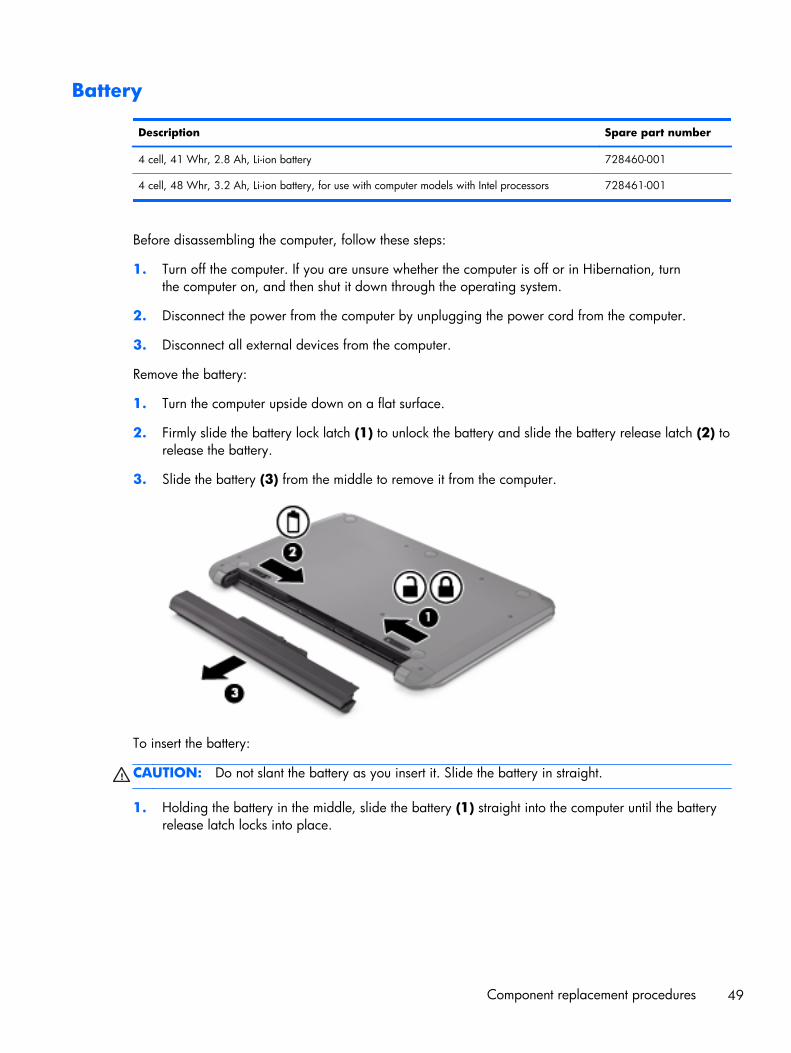
Battery
Description Spare part number
4 cell, 41 Whr, 2.8 Ah, Li-ion battery 728460-001
4 cell, 48 Whr, 3.2 Ah, Li-ion battery, for use with computer models with Intel processors 728461-001
Before disassembling the computer, follow these steps:
1. Turn off the computer. If you are unsure whether the computer is off or in Hibernation, turnthe computer on, and then shut it down through the operating system.
2. Disconnect the power from the computer by unplugging the power cord from the computer.
3. Disconnect all external devices from the computer.
Remove the battery:
1. Turn the computer upside down on a flat surface.
2. Firmly slide the battery lock latch (1) to unlock the battery and slide the battery release latch (2) torelease the battery.
3. Slide the battery (3) from the middle to remove it from the computer.
To insert the battery:
CAUTION: Do not slant the battery as you insert it. Slide the battery in straight.
1. Holding the battery in the middle, slide the battery (1) straight into the computer until the batteryrelease latch locks into place.
Component replacement procedures 49

2. Reset the battery lock latch (2) to the locked position.
Service door
Description Spare part number
Service door is available with the Plastics Kit. 734419-001
1. Using a small Phillips screwdriver, loosen the service door screw (1).
2. Lift the door (2).
3. Slide the service door (3) forward to remove.
50 Chapter 5 Removal and replacement procedures for Customer Self-Repair parts

Memory module
Description Spare part number
4 GB memory module (PC3, 12800, 1600 MHz) 691740-001
2 GB memory module (PC3, 12800, 1600 MHz) 691739-001
8 GB memory module (PC3, 12800, 1600 MHz) 693374-001
NOTE: Before adding memory modules, make sure the computer has the most recent BIOS version,and update the BIOS if needed. For Windows operating systems, see Updating the BIOSon page 105; for Linux Ubuntu, see Updating the BIOS on page 110.
Before removing a memory module, follow these steps:
1. Turn off the computer. If you are unsure whether the computer is off or in Hibernation, turnthe computer on, and then shut it down through the operating system.
2. Disconnect the power from the computer by unplugging the power cord from the computer.
3. Disconnect all external devices from the computer.
4. Remove the battery (see Battery on page 49).
5. Remove the service door (see Service door on page 50).
Remove the memory module:
NOTE: Note the location of the memory module (1) you are removing. If you are replacing it, installthe new memory module in the same slot.
1. Spread the two retaining tabs (1) on each side of the memory module slot to releasethe memory module. (The memory module tilts up.)
Component replacement procedures 51

2. Remove the memory module (2) by pulling it away from the slot at a 45 degree angle.
Reverse this procedure to install the memory module.
52 Chapter 5 Removal and replacement procedures for Customer Self-Repair parts

WLAN module
Description Spare part number
Intel Wireless-N 7260BN 802.11 bgn 2x2 Wi-Fi + BT 4.0 combo adaptor for use with computermodels with Intel processors; not supported on Ubuntu
717384-001
Mediatek MT7630E 802.11 bgn Wi-Fi Adapter and Mediatek Bluetooth 4.0 Adapter for use withcomputer models with Intel processors
710418-001
Qualcomm Atheros AR9485 802.11 bgn Wi-Fi Adapter 675794-001
Ralink RT3290LE 802.11 bgn 1×1 Wi-Fi and Bluetooth 4.0 Combo Adapter 690020-001
Realtek RTL8188EE 802.11 bgn Wi-Fi Adapter 709848-001
CAUTION: To prevent an unresponsive system, replace the wireless module only with a wirelessmodule authorized for use in the computer by the governmental agency that regulates wireless devicesin your country or region. If you replace the module and then receive a warning message, removethe module to restore device functionality, and then contact technical support.
Before removing the WLAN module, follow these steps:
1. Turn off the computer. If you are unsure whether the computer is off or in Hibernation, turnthe computer on, and then shut it down through the operating system.
2. Disconnect the power from the computer by unplugging the power cord from the computer.
3. Disconnect all external devices from the computer.
4. Remove the battery (see Battery on page 49).
5. Remove the service door (see Service door on page 50).
6. Locate the WLAN module (1).
Component replacement procedures 53
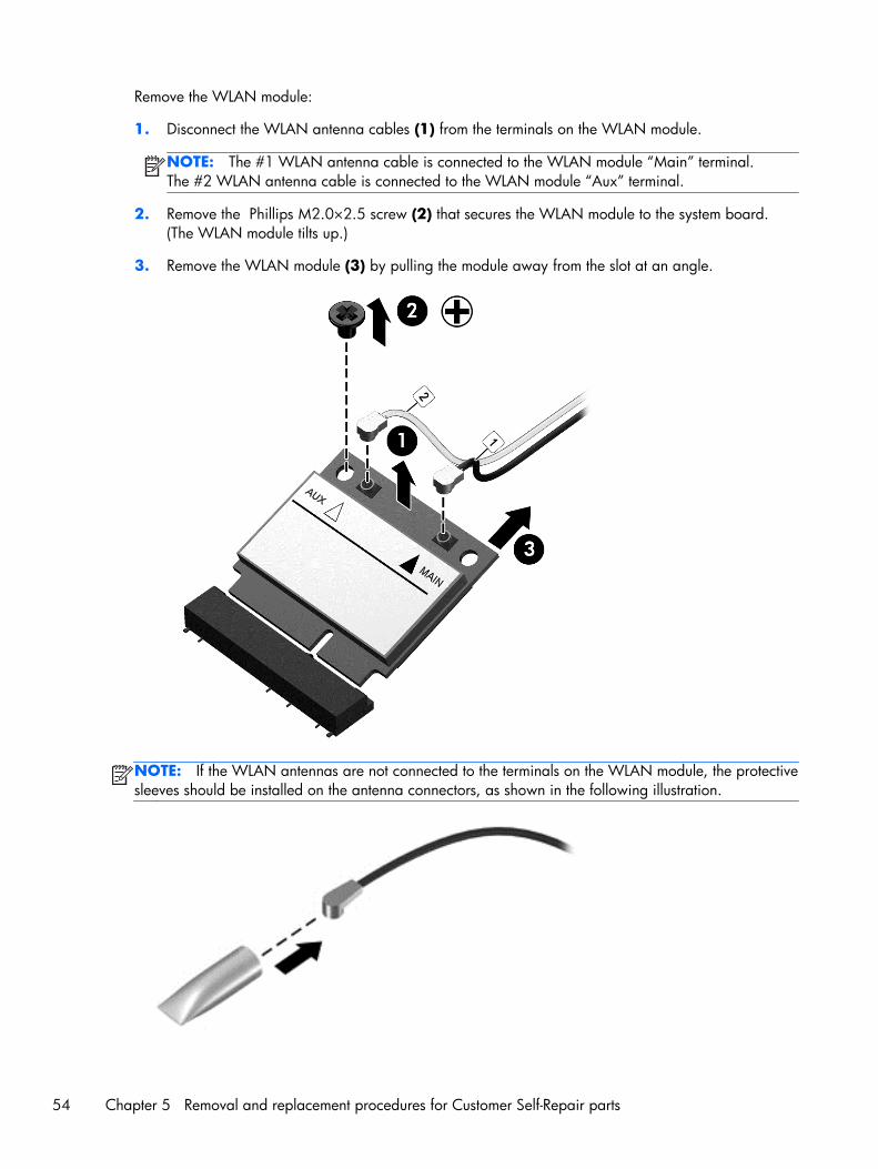
Remove the WLAN module:
1. Disconnect the WLAN antenna cables (1) from the terminals on the WLAN module.
NOTE: The #1 WLAN antenna cable is connected to the WLAN module “Main” terminal.The #2 WLAN antenna cable is connected to the WLAN module “Aux” terminal.
2. Remove the Phillips M2.0×2.5 screw (2) that secures the WLAN module to the system board.(The WLAN module tilts up.)
3. Remove the WLAN module (3) by pulling the module away from the slot at an angle.
NOTE: If the WLAN antennas are not connected to the terminals on the WLAN module, the protectivesleeves should be installed on the antenna connectors, as shown in the following illustration.
54 Chapter 5 Removal and replacement procedures for Customer Self-Repair parts
Reverse this procedure to install the WLAN module.
Optical drive
NOTE: The optical drive spare part kit includes a bezel and bracket.
Description Spare part number
Optical drive, SuperMulti DVD±R/RW Double-Layer Drive (includes bezel, bracket, and screws) 734415-001
Before removing the optical drive, follow these steps:
1. Turn off the computer. If you are unsure whether the computer is off or in Hibernation, turnthe computer on, and then shut it down through the operating system.
2. Disconnect the power from the computer by unplugging the power cord from the computer.
3. Disconnect all external devices from the computer.
4. Remove the battery (see Battery on page 49).
Remove the optical drive:
1. Using a small Phillips screwdriver, remove the Phillips M2.5×6.5 screw that secures the opticaldrive to the computer (1).
2. Using the screwdriver, push on the rear of the optical drive to disconnect it from the computer
Component replacement procedures 55
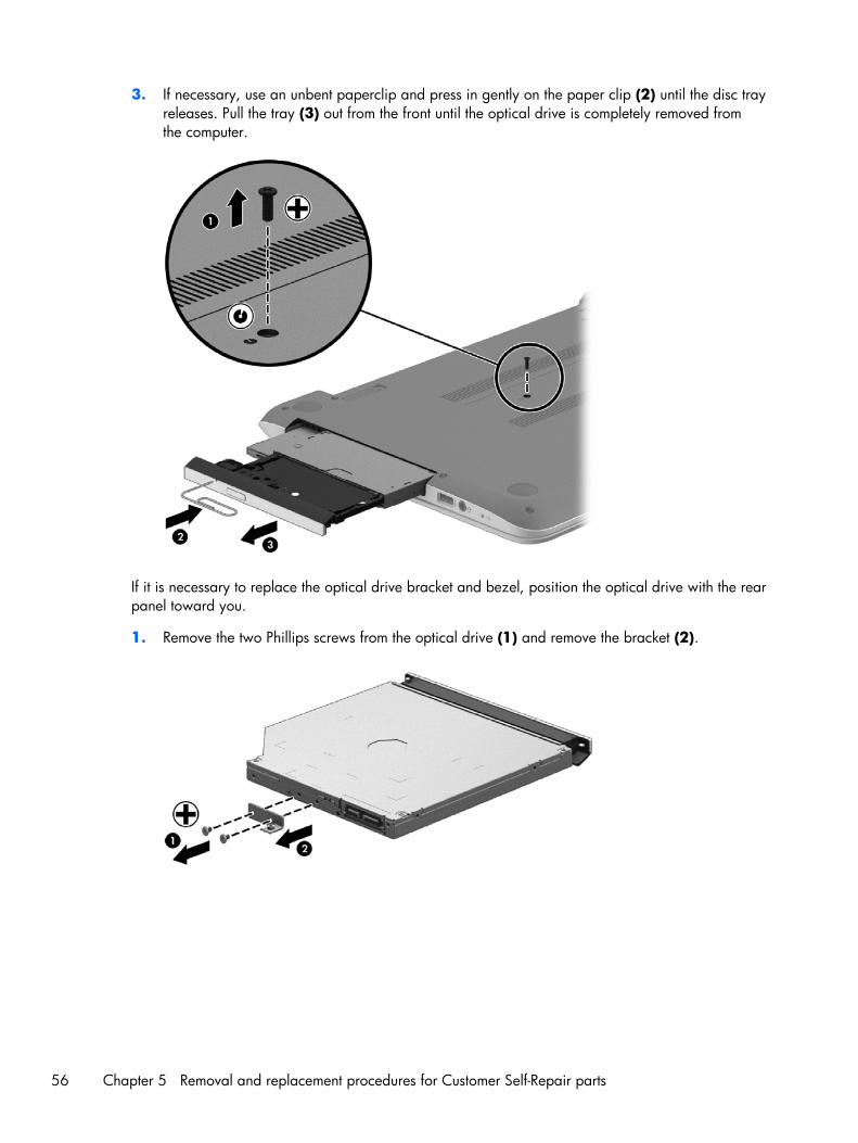
3. If necessary, use an unbent paperclip and press in gently on the paper clip (2) until the disc trayreleases. Pull the tray (3) out from the front until the optical drive is completely removed fromthe computer.
If it is necessary to replace the optical drive bracket and bezel, position the optical drive with the rearpanel toward you.
1. Remove the two Phillips screws from the optical drive (1) and remove the bracket (2).
56 Chapter 5 Removal and replacement procedures for Customer Self-Repair parts

2. Use an unbent paperclip and press in gently on the paper clip (1) and release from the tab (2)until the disc tray releases. Tilt the tray (3) and pull the bezel (4) to remove it.
Reverse this procedure to reassemble and install the optical drive.
Component replacement procedures 57
6 Removal and replacementprocedures for Authorized ServiceProvider parts
NOTE: HP continually improves and changes product parts. For complete and current information onsupported parts for your computer, go to http://partsurfer.hp.com, select your country or region, andthen follow the on-screen instructions.
CAUTION: Components described in this chapter should only be accessed by an authorized serviceprovider. Accessing these parts can damage the computer or void the warranty.
Component replacement proceduresNOTE: Details about your computer, including model, serial number, product key, and length ofwarranty, are on the service tag at the bottom of your computer. See Labels on page 19 for details.
This chapter provides removal and replacement procedures for Authorized Service Provider only parts.
There may be as many as 51 screws that must be removed, replaced, and/or loosened when servicingAuthorized Service Provider only parts. Make special note of each screw size and location duringremoval and replacement.
58 Chapter 6 Removal and replacement procedures for Authorized Service Provider parts

Display panel
NOTE: These procedures are for replacing the display panel for HP Pavilion Notebook. Forprocedures to replace the HP Pavilion Notebook display assembly subcomponents, see Displayassembly on page 98 and then Display assembly subcomponents on page 101. For procedures toreplace the HP Pavilion TouchSmart display assembly, see Display assembly on page 98.
Description Spare part number
Display bezel (includes 2 rubber screws) 739355-001
Display panel, 35.56 cm (14 in), WLED, HD, BrightView flat display panel 734420-001
IMPORTANT: Make special note of each screw and screw lock size and location during removaland replacement
Before removing the display panel, follow these steps:
1. Turn off the computer. If you are unsure whether the computer is off or in Hibernation, turnthe computer on, and then shut it down through the operating system.
2. Disconnect the power from the computer by unplugging the power cord from the computer.
3. Disconnect all external devices from the computer.
4. Remove the battery (see Battery on page 49).
Remove the panel:
If it is necessary to replace the display bezel:
1. Remove the plastic screw covers (1) and the two Phillips M2.5×3.0 screws (2) that securethe display bezel to the display assembly.
2. If it is necessary to replace the display bezel or any of the display assembly subcomponents:
a. Flex the inside edges of the bottom edge (3), the left and right sides (4), and the top edge(5) of the display bezel until the bezel disengages from the display enclosure.
Component replacement procedures 59

b. Remove the display bezel (6).
60 Chapter 6 Removal and replacement procedures for Authorized Service Provider parts

c. Remove the four Phillips M2.0×2.5 screws (1) and carefully move the display panel (2) tothe keyboard.
Release the tab (1) and disconnect the display panel cable connector (2). Lift the panel (3)to remove it.
Reverse this procedure to replace the panel.
Component replacement procedures 61

Keyboard
NOTE: The keyboard spare part kit includes a keyboard cable.
Description Spare part number
Textured island-style black finish for use in the United States 740102-001
Textured island-style black finish for use in United Kingdom 740102-031
Textured island-style black finish for use in Germany 740102-041
Textured island-style black finish for use in France 740102-051
Textured island-style black finish for use in Spain 740102-071
Textured island-style black finish for use in Portugal 740102-131
Textured island-style black finish for use in Turkey 740102-141
Textured island-style black finish for use in Latin America 740102-161
Textured island-style black finish for use in Saudi Arabia 740102-171
Textured island-style black finish for use in Brazil 740102-201
Textured island-style black finish for use in Russia 740102-251
Textured island-style black finish for use in Thailand 740102-281
Textured island-style black finish for use in Japan 740102-291
Textured island-style black finish for use in Taiwan 740102-AB1
Textured island-style black finish for use in South Korea 740102-AD1
Textured island-style black finish for International use 740102-B31
Textured island-style black finish for use in Israel 740102-BB1
Textured island-style black finish for use in Switzerland 740102-BG1
Textured island-style black finish for use in Canada 740102-DB1
Textured island-style black finish for use in Nordic regions 740102-DH1
Textured island-style black finish for use in the Czech Republic and Slovak Republic, for use withcomputer models with Intel processors
740102-FL1
Painted island-style white finish for use in the United States 740103-001
Painted island-style white finish for use in the United Kingdom, for use with computer models withIntel processors
740103-031
Painted island-style white finish for use in Greece, for use with computer models with Intelprocessors
740103-041
Painted island-style white finish for use in France, for use with computer models with Intelprocessors
740103-051
Painted island-style white finish for use in Spain, for use with computer models with Intel processors 740103-071
62 Chapter 6 Removal and replacement procedures for Authorized Service Provider parts

Description Spare part number
Painted island-style white finish for use in Portugal, for use with computer models with Intelprocessors
740103-131
Painted island-style white finish for use in Turkey, for use with computer models with Intelprocessors
740103-141
Painted island-style white finish for use in Latin America 740103-161
Painted island-style white finish for use in Saudi Arabia, for use with computer models with Intelprocessors
740103-171
Painted island-style white finish for use in Brazil, for use with computer models with Intel processors 740103-201
Painted island-style white finish for use in Russia, for use with computer models with Intelprocessors
740103-251
Painted island-style white finish for use in Thailand 740103-281
Painted island-style white finish for use in Japan, for use with computer models with Intelprocessors
740597-291
Painted island-style white finish for use in Taiwan 740103-AB1
Painted island-style white finish for use in Korea 740103-AD1
Painted island-style white finish for International use, for use with computer models with Intelprocessors
740103-B31
Painted island-style white finish for use in Israel, for use with computer models with Intel processors 740103-BB1
Painted island-style white finish for use in Switzerland, for use with computer models with Intelprocessors
740103-BG1
Painted island-style white finish for use in Canada 740103-DB1
Painted island-style white finish for use in Nordic regions, for use with computer models with Intelprocessors
740103-DH1
Painted island-style white finish for use in the Czech Republic and Slovak Republic, for use withcomputer models with Intel processors
740103-FL1
Before removing the keyboard, follow these steps:
1. Turn off the computer. If you are unsure whether the computer is off or in Hibernation, turnthe computer on, and then shut it down through the operating system.
2. Disconnect the power from the computer by unplugging the power cord from the computer.
3. Disconnect all external devices from the computer.
4. Remove the battery (see Battery on page 49).
Component replacement procedures 63

Remove the keyboard:
1. Remove the 2 Phillips M2.5×6.5 screws that secure the keyboard to the computer.
2. Rest the computer on its left side.
3. Open the computer.
64 Chapter 6 Removal and replacement procedures for Authorized Service Provider parts

4. Insert a thin tool or a keyboard push tool into the left retention screw hole, and then press onthe back of the keyboard until the keyboard disengages from the computer.
5. Turn the computer right-side up with the front toward you.
Component replacement procedures 65
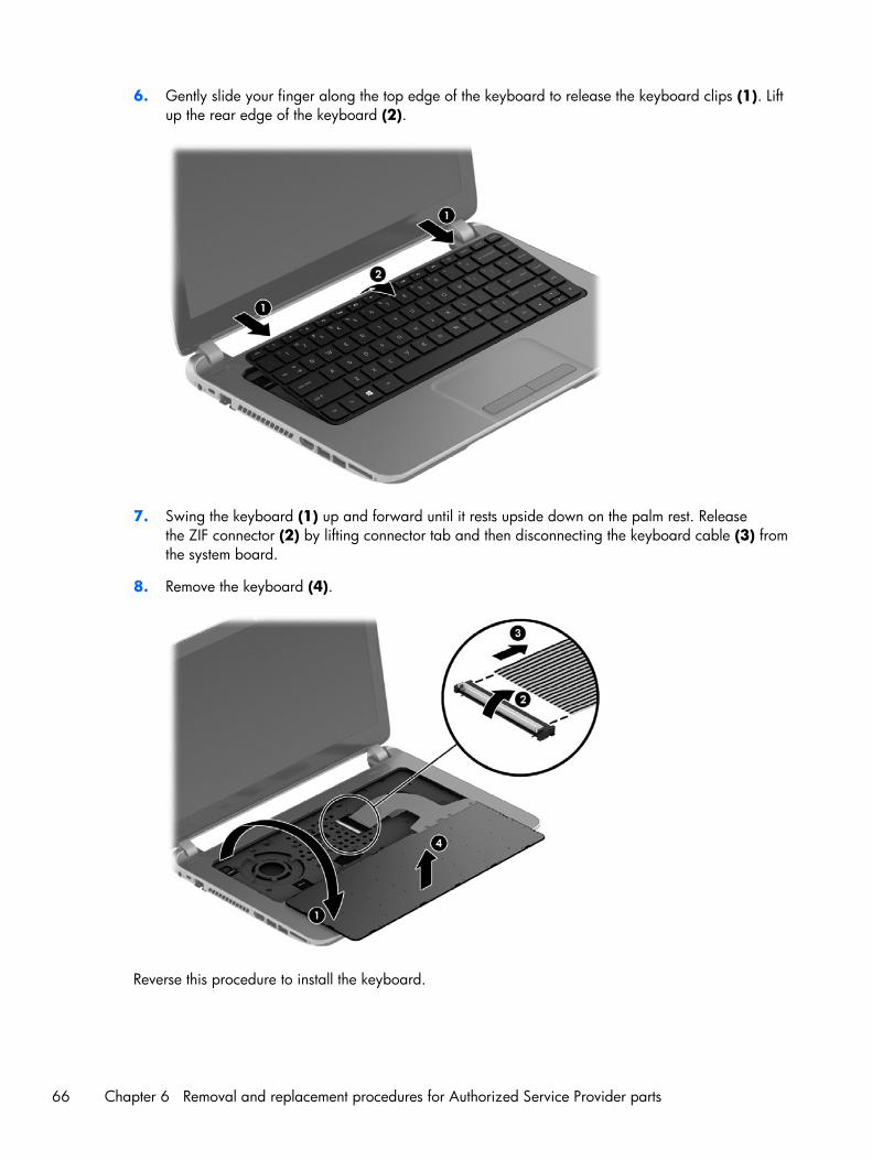
6. Gently slide your finger along the top edge of the keyboard to release the keyboard clips (1). Liftup the rear edge of the keyboard (2).
7. Swing the keyboard (1) up and forward until it rests upside down on the palm rest. Releasethe ZIF connector (2) by lifting connector tab and then disconnecting the keyboard cable (3) fromthe system board.
8. Remove the keyboard (4).
Reverse this procedure to install the keyboard.
66 Chapter 6 Removal and replacement procedures for Authorized Service Provider parts

Top cover
NOTE: The top cover spare part kit includes the TouchPad and cable.
Description Spare part number
Aluminum with midnight black finish 734435-001
Flyer red finish 734431-001
Goji berry finish 736818-001
Hazel berry finish 736819-001
Mineral black finish 736817-001
Pearl white finish 734430-001
Raspberry finish 736820-001
Revolutionary blue finish 734432-001
Regal purple finish 734433-001
Sparkling black finish 734434-001
IMPORTANT: Make special note of each screw and screw lock size and location during removaland replacement
Before removing the top cover, follow these steps:
1. Shut down the computer.
2. Disconnect all external devices connected to the computer.
3. Disconnect the power from the computer by first unplugging the power cord from the AC outletand then unplugging the AC adapter from the computer.
4. Remove the battery (see Battery on page 49), and then remove the following components:
a. Optical drive (see Optical drive on page 55)
b. Keyboard (see Keyboard on page 62)
c. Service door (see Service door on page 50)
d. WLAN module (see WLAN module on page 53)
e. Memory module (see Memory module on page 51)
Component replacement procedures 67

Remove the top cover:
1. Remove the 5 Phillips M2.5×3.0 screws that secure the top cover to the base enclosure.
2. Disconnect the power button cable (1) and the TouchPad cable (2).
68 Chapter 6 Removal and replacement procedures for Authorized Service Provider parts

3. Close the display and turn the computer upside down.
4. Remove the 8 Phillips M2.5×6.5 screws from the bottom of the computer.
5. Turn the computer over and open the display.
6. Gently pull on the right upper corner (1) and lift around the edges of the top cover (2). Lift toremove the top cover (3).
Component replacement procedures 69

When replacing the top cover, be sure that the following components are removed from the defectivetop cover and installed on the replacement top cover:
● Power button board and cable (see Power button board on page 75)
● Touchpad button board (includes cable and buttons), (see TouchPad button board on page 77)
● USB/audio board (instructions are included in the steps for removing the hard drive; see Harddrive on page 71)
Reverse this procedure to install the top cover.
70 Chapter 6 Removal and replacement procedures for Authorized Service Provider parts

Hard drive
NOTE: The hard drive spare part kit does not include the hard drive rubber bracket, hard driveconnector cable, or screws. These components are included in the Hard Drive Hardware Kit, spare partnumber 740706-001.
Description Spare part number
1 TB, 5400 rpm, 9.5 mm 676521-005
750 GB, 5400 rpm, 9.5 mm 634250-005
500 GB, 5400 rpm, 7.0 mm 683802-005
mSATA solid-state drive, 24 GB (for use with select computer models with Intel processors, HM86Express chipsets, and switchable discrete graphics)
732085-001
Before removing the hard drive, follow these steps:
1. Turn off the computer. If you are unsure whether the computer is off or in Hibernation, turnthe computer on, and then shut it down through the operating system.
2. Disconnect the power from the computer by unplugging the power cord from the computer.
3. Disconnect all external devices from the computer.
4. Remove the battery (see Battery on page 49), and then remove the following components:
a. Optical drive (see Optical drive on page 55)
b. Keyboard (see Keyboard on page 62)
c. Service door (see Service door on page 50)
d. WLAN module (see WLAN module on page 53)
e. Memory module (see Memory module on page 51)
f. Top cover (see Top cover on page 67)
Component replacement procedures 71

Remove the hard drive:
1. Disconnect the USB/audio cable (1) by flipping the connector and lifting the cable. Remove theUSB/audio cable Phillips M 2.5×3.0 screw (2) and then lift the USB/audio board (3). The USB/audio board spare part number is 734417-001.
72 Chapter 6 Removal and replacement procedures for Authorized Service Provider parts
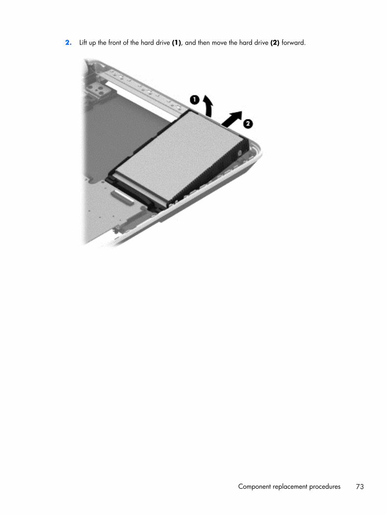
2. Lift up the front of the hard drive (1), and then move the hard drive (2) forward.
Component replacement procedures 73

3. Disconnect the hard drive connector cable from the hard drive.
4. If it is necessary to disassemble the hard drive, perform the following steps:
a. Remove the four Phillips M3.0×3.5 screws (1) from the bracket.
b. Remove the bracket (2) from the hard drive.
Reverse this procedure to reassemble and install the hard drive.
74 Chapter 6 Removal and replacement procedures for Authorized Service Provider parts

Power button board
Description Spare part number
Power button board (includes cable) 734416-001
Before removing the power button board, follow these steps:
1. Turn off the computer. If you are unsure whether the computer is off or in Hibernation, turnthe computer on, and then shut it down through the operating system.
2. Disconnect the power from the computer by unplugging the power cord from the computer.
3. Disconnect all external devices from the computer.
4. Remove the battery (see Battery on page 49), and then remove the following components:
a. Optical drive (see Optical drive on page 55)
b. Service door (see Service door on page 50)
c. Keyboard (see Keyboard on page 62)
d. WLAN module (see WLAN module on page 53)
e. Memory module (see Memory module on page 51)
f. Top cover (see Top cover on page 67)
Remove the power button board:
1. Turn the top cover upside down, with the front toward you.
2. Remove the Phillips PM2.5×2.5 screw (1) that secures the power button board to the top cover.
Component replacement procedures 75

3. Remove the power button board (2) with cable (the cable was disconnected when removing thetop cover).
Reverse this procedure to install the power button board.
76 Chapter 6 Removal and replacement procedures for Authorized Service Provider parts

TouchPad button board
Description Spare part number
TouchPad button board (includes cable) 734418-001
Before removing the TouchPad button board, follow these steps:
1. Turn off the computer. If you are unsure whether the computer is off or in Hibernation, turnthe computer on, and then shut it down through the operating system.
2. Disconnect the power from the computer by unplugging the power cord from the computer.
3. Disconnect all external devices from the computer.
4. Remove the battery (see Battery on page 49), and then remove the following components:
a. Optical drive (see Optical drive on page 55)
b. Service door (see Service door on page 50)
c. WLAN module (see WLAN module on page 53)
d. Memory module (see Memory module on page 51)
e. Keyboard (see Keyboard on page 62)
f. Top cover (see Top cover on page 67)
Remove the TouchPad button board:
1. Turn the top cover upside down, with the front toward you.
2. Release the TouchPad ZIF connector, and then disconnect the TouchPad button board cable (1)from the TouchPad board.
3. Remove the 3 Phillips PM2.0×3.5 screws (2) that secures the TouchPad button board bracket tothe top cover.
4. Remove the TouchPad button board (3) carefully lifting the cable from the guides (the cable wasdisconnected when removing the top cover).
5. Lift up the TouchPad button board (4).
Component replacement procedures 77

6. Remove the TouchPad button board (5).
Reverse this procedure to install the TouchPad button board.
Optical drive connector cable
NOTE: The optical drive connector cable is included with the Optical Drive, spare part number734415-001.
Before removing the optical drive connector cable, follow these steps:
1. Turn off the computer. If you are unsure whether the computer is off or in Hibernation, turnthe computer on, and then shut it down through the operating system.
2. Disconnect the power from the computer by unplugging the power cord from the computer.
3. Disconnect all external devices from the computer.
4. Remove the battery (see Battery on page 49), and then remove the following components:
a. Optical drive (see Optical drive on page 55)
b. Service door (see Service door on page 50)
c. WLAN module (see WLAN module on page 53)
d. Memory module (see Memory module on page 51)
78 Chapter 6 Removal and replacement procedures for Authorized Service Provider parts
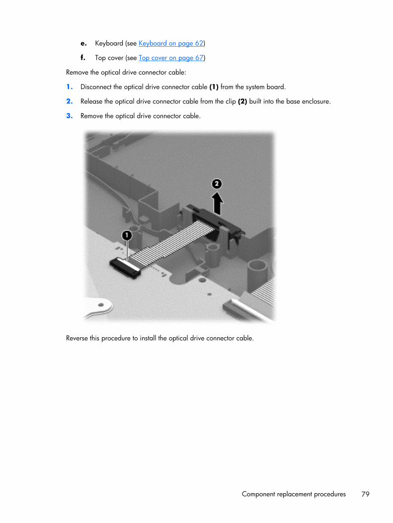
e. Keyboard (see Keyboard on page 62)
f. Top cover (see Top cover on page 67)
Remove the optical drive connector cable:
1. Disconnect the optical drive connector cable (1) from the system board.
2. Release the optical drive connector cable from the clip (2) built into the base enclosure.
3. Remove the optical drive connector cable.
Reverse this procedure to install the optical drive connector cable.
Component replacement procedures 79

System board
NOTE: The system board spare part kit includes replacement thermal material.
Description Spare part number
For computer models equipped with Intel processors and UMA graphics
4th generation
Intel Core i5-4200U 1.6 GHz processor (3.0 MB L3 cache, 15 W) for use with FreeDOS andUbuntu
734423-001
Intel Core i5-4200U 1.6 GHz processor (3.0 MB L3 cache, 15 W) for use with WindowsStandard
734423-501
Intel Core i5-4200U 1.6 GHz processor (3.0 MB L3 cache, 15 W) for use with WindowsProfessional
734423-601
Intel Core i3-4005U 1.7 GHz processor (3.0 MB L3 cache, 15 W) for use with FreeDOS andUbuntu
734424-001
Intel Core i3-4005U 1.7 GHz processor (3.0 MB L3 cache, 15 W) for use with WindowsStandard
734424-501
Intel Core i3-4005U 1.7 GHz processor (3.0 MB L3 cache, 15 W) for use with WindowsProfessional
734424-601
For computer models equipped with Intel processors and UMA graphics
3rd generation
Pentium 2117U HM76 (1.8 GHz, 2 MB L3 Cache, 1600 MHz DDR3, 17 W) for use withFreeDOS and Ubuntu
738148-001
Pentium 2117U HM76 (1.8 GHz, 2 MB L3 Cache, 1600 MHz DDR3, 17 W) for use withWindows Standard
738148-501
Pentium 2117U HM76 (1.8 GHz, 2 MB L3 Cache, 1600 MHz DDR3, 17 W) for use withWindows Professional
738148-601
Core i3-3217U (1. 8GHz, 3 MB L3 Cache, 1600 MHz DDR3, 17 W) for use with FreeDOS andUbuntu
738150-001
Core i3-3217U (1.8 GHz, 3 MB L3 Cache, 1600 MHz DDR3, 17 W) for use with WindowsStandard
738150-501
Core i3-3217U (1.8 GHz, 3 MB L3 Cache, 1600 MHz DDR3, 17 W) for use with WindowsProfessional
738150-601
For computer models equipped with Intel processors and switchable discretegraphics
4th generation
NVIDIA N14P-GV2 GeForce GT 740M 2 GB graphics and Intel Core i7-4500U (1.8 GHz DC,15 W) for use with FreeDOS and Ubuntu
738154-001
NVIDIA N14P-GV2 GeForce GT 740M 2 GB graphics and Intel Core i7-4500U (1.8 GHz DC,15 W) for use with Windows Standard
738154-501
80 Chapter 6 Removal and replacement procedures for Authorized Service Provider parts

Description Spare part number
NVIDIA N14P-GV2 GeForce GT 740M 2 GB graphics and Intel Core i7-4500U (1.8 GHz DC,15 W) for use with Windows Professional
738154-601
NVIDIA N14P-GV2 GeForce GT 740M 2 GB graphics and Intel Core i5-4200U (1.6 GHz DC,15 W) for use with FreeDOS and Ubuntu
738156-001
NVIDIA N14P-GV2 GeForce GT 740M 2 GB graphics and Intel Core i5-4200U (1.6 GHz DC,15 W) for use with Windows Standard
738156-501
NVIDIA N14P-GV2 GeForce GT 740M 2 GB graphics and Intel Core i5-4200U (1.6 GHz DC,15 W) for use with Windows Professional
738156-601
AMD Radeon 8670M 2 GB graphics and Intel Core i7-4500U (1.8 GHz DC, 15 W) for use withFreeDOS and Ubuntu
734429-001
AMD Radeon 8670M 2 GB graphics and Intel Core i7-4500U (1.8 GHz DC, 15 W) for use withWindows Standard
734429-501
AMD Radeon 8670M 2 GB graphics and Intel Core i7-4500U (1.8 GHz DC, 15 W) for use withWindows Professional
734429-601
AMD Radeon 8670M 2 GB graphics and Intel Core i5-4200U (1.6 GHz, DC 15 W) for use withFreeDOS and Ubuntu
734429-001
AMD Radeon 8670M 2 GB graphics and Intel Core i5-4200U (1.6 GHz, DC 15 W) for use withWindows Standard
734426-501
AMD Radeon 8670M 2 GB graphics and Intel Core i5-4200U (1.6 GHz, DC 15 W) for use withWindows Professional
734426-601
AMD Radeon 8670M 1 GB graphics and Intel Core i3-4005U (1.7 GHz, DC 15 W) for use withFreeDOS and Ubuntu
734427-001
AMD Radeon 8670M 1 GB graphics and Intel Core i3-4005U (1.7 GHz, DC 15 W) for use withWindows Standard
734427-501
AMD Radeon 8670M 1 GB graphics and Intel Core i3-4005U (1.7 GHz, DC 15 W) for use withWindows Professional
734427-601
For computer models equipped with Intel processors and switchable discretegraphics
3rd generation
AMD Radeon 8670M 2 GB graphics and Intel Core i3-3217U (1.8 GHz, L3 Cache, 1600 MHzDDR3, 17 W) for use with FreeDOS and Ubuntu
738152-001
AMD Radeon 8670M 2 GB graphics and Intel Core i3-3217U (1.8 GHz, L3 Cache, 1600 MHzDDR3, 17 W) for use with Windows Standard
738152-501
AMD Radeon 8670M 2 GB graphics and Intel Core i3-3217U (1.8 GHz, L3 Cache, 1600 MHzDDR3, 17 W) for use with Windows Professional
738152-601
For computer models equipped with AMD processors and UMA graphics
AMD A4-5000 (1.5 GHz, 2 MB L2, 1600 MHz DDR3L, quad core, 15 W) for use with FreeDOSand Ubuntu
734443-001
AMD A4-5000 (1.5 GHz, 2 MB L2, 1600 MHz DDR3L, quad core, 15 W) for use with WindowsStandard
734443-501
Component replacement procedures 81

Description Spare part number
AMD A76M chipset, A6-4455M processor (2.6 GHz/2.1 GHz, 2 MB L2, 1333 MHz DDR3Ldual core, 19 W) for use with FreeDOS and Ubuntu
736821-001
AMD A76M chipset, A6-4455M processor (2.6 GHz/2.1 GHz, 2 MB L2, 1333 MHz DDR3Ldual core, 19 W) for use with Windows Standard
736821-501
AMD A6-5200 (2.6 GHz/2.1 GHz, 2 MB L2, 1600 MHz DDR3L, dual core, 17 W) for use withFreeDOS and Ubuntu
734444-001
AMD A6-5200 (2.6 GHz/2.1 GHz, 2 MB L2, 1600 MHz DDR3L, dual core, 17 W) for use withWindows Standard
734444-501
AMD A8-5545M A76M (2.7 GHz/1.7 GHz, 4 MB L2, 1333 MHz DDR3L quad core, 19 W) foruse with FreeDOS and Ubuntu
734446-001
AMD A8-5545M A76M (2.7 GHz/1.7 GHz, 4 MB L2, 1333 MHz DDR3L quad core, 19 W) foruse with Windows Standard
734446-501
AMD A76M chipset, A8-4555M processor (2.4 GHz/1.6 GHz, 4 MB L2, 1333 MHz DDR3Lquad core, 19 W) for use with FreeDOS and Ubuntu
736822-001
AMD A76M chipset, A8-4555M processor (2.4 GHz/1.6 GHz, 4 MB L2, 1333 MHz DDR3Lquad core, 19 W) for use with Windows Standard
736822-501
AMD E2-3000 (1.65 GHz, 1 MB L2, 1600 MHz DDR3L, dual core, 15 W) for use with FreeDOSand Ubuntu
734447-001
AMD E2-3000 (1.65 GHz, 1 MB L2, 1600 MHz DDR3L, dual core, 15 W) for use with WindowsStandard
734447-501
For computer models equipped with AMD processors and switchable discretegraphics
AMD Radeon 8670M 1 GB graphics and A6-5200 processor (2.6 GHz/2.1 GHz, 2 MB L2,1600 MHz DDR3L, dual core, 17 W) for use with FreeDOS and Ubuntu
734440-001
AMD Radeon 8670M 1 GB graphics and A6-5200 processor (2.6 GHz/2.1 GHz, 2 MB L2,1600 MHz DDR3L, dual core, 17 W) for use with Windows Standard
734440-501
AMD Radeon 8670M 2 GB graphics and A10-5745M processor (2.9 GHz/2.1 GHz, 4 MB L2,1333 MHz DDR3L quad core, 25 W) for use with FreeDOS and Ubuntu
734441-001
AMD Radeon 8670M 2 GB graphics and A10-5745M processor (2.9 GHz/2.1 GHz, 4 MB L2,1333 MHz DDR3L quad core, 25 W) for use with FreeDOS and Ubuntu
734441-001
Before removing the system board, follow these steps:
1. Turn off the computer. If you are unsure whether the computer is off or in Hibernation, turnthe computer on, and then shut it down through the operating system.
2. Disconnect the power from the computer by unplugging the power cord from the computer.
82 Chapter 6 Removal and replacement procedures for Authorized Service Provider parts

3. Disconnect all external devices from the computer.
4. Remove the battery (see Battery on page 49), and then remove the following components:
a. Optical drive (see Optical drive on page 55)
b. Service door (see Service door on page 50)
c. WLAN module (see WLAN module on page 53)
d. Memory module (see Memory module on page 51)
e. Keyboard (see Keyboard on page 62)
f. Top cover (see Top cover on page 67)
g. Hard drive (see Hard drive on page 71)
When replacing the system board, be sure that the following components are removed fromthe defective system board and installed on the replacement system board:
● Hard drive connector cable
● Power connector cable (see Power connector cable on page 95)
● RTC battery (see RTC battery on page 87)
● Fan (see Fan on page 89)
● Heat sink assembly (see Heat sink assembly on page 91)
Remove the system board:
1. Disconnect the following cables from the system board:
● Display panel cable (1)
● Speaker cable (2)
Component replacement procedures 83

2. Remove the Phillips PM2.5×6.5 screw (1) that secures the power connector bracket tothe base enclosure. Remove the power connector bracket (2).
3. Remove the 2 Phillips M2.5×5.0 screws (1) that secure the system board to the base enclosure.
4. Lift the right side of the system board (2) until it rests at an angle.
84 Chapter 6 Removal and replacement procedures for Authorized Service Provider parts

5. Carefully remove from the power connector (3). Remove the system board (4) by sliding it upand to the right at an angle.
6. Remove the hard drive connector cable:
a. Turn the system board upside down, with the front toward you.
Component replacement procedures 85

b. Disconnect the hard drive connector cable from the system board. The hard drive cable ispart of the Hard Drive Hardware Kit, part number 740706-001.
Reverse this procedure to install the system board.
86 Chapter 6 Removal and replacement procedures for Authorized Service Provider parts

RTC battery
Description Spare part number
RTC battery 697917-001
Before removing the RTC battery, follow these steps:
1. Turn off the computer. If you are unsure whether the computer is off or in Hibernation, turnthe computer on, and then shut it down through the operating system.
2. Disconnect the power from the computer by unplugging the power cord from the computer.
3. Disconnect all external devices from the computer.
4. Remove the battery (see Battery on page 49), and then remove the following components:
a. Optical drive (see Optical drive on page 55)
b. Service door (see Service door on page 50)
c. Remove the WLAN module (see WLAN module on page 53)
d. Remove the Memory module (see Memory module on page 51)
e. Keyboard (see Keyboard on page 62)
f. Top cover (see Top cover on page 67)
g. Hard drive (see Hard drive on page 71)
h. System board (see System board on page 80)
Remove the RTC battery:
1. Turn the system board upside down, with the front toward you.
2. Use a flat-bladed, non-metallic tool (1) to release the RTC battery from the socket on thesystem board. The battery is spring loaded and will pop up.
Component replacement procedures 87

3. Remove the RTC battery (2).
Reverse this procedure to install the RTC battery. When installing the RTC battery, make sure the “+”sign faces up.
88 Chapter 6 Removal and replacement procedures for Authorized Service Provider parts

Fan
Description Spare part number
Fan 732068-001
NOTE: To properly ventilate the computer, allow at least 7.6 cm (3 in) of clearance on the left side ofthe computer. The computer uses an electric fan for ventilation. The fan is controlled by a temperaturesensor and is designed to turn on automatically when high temperature conditions exist. Theseconditions are affected by high external temperatures, system power consumption, powermanagement/battery conservation configurations, battery fast charging, and software requirements.Exhaust air is displaced through the ventilation grill located on the left side of the computer.
Before removing the fan, follow these steps:
1. Turn off the computer. If you are unsure whether the computer is off or in Hibernation, turnthe computer on, and then shut it down through the operating system.
2. Disconnect the power from the computer by unplugging the power cord from the computer.
3. Disconnect all external devices from the computer.
4. Remove the battery (see Battery on page 49), and then remove the following components:
a. Optical drive (see Optical drive on page 55)
b. Service door (see Service door on page 50)
c. WLAN module (see WLAN module on page 53)
d. Memory module (see Memory module on page 51)
e. Keyboard (see Keyboard on page 62)
f. Top cover (see Top cover on page 67)
g. Hard drive (see Hard drive on page 71)
h. System board (see System board on page 80)
Remove the fan:
1. Turn the system board upside down, with the front toward you.
2. Disconnect the fan cable (1) from the system board.
3. Remove the 2 screws (2) that secure the fan to the system board.
Component replacement procedures 89

4. Remove the fan (3) from the system board.
Reverse this procedure to install the fan.
90 Chapter 6 Removal and replacement procedures for Authorized Service Provider parts

Heat sink assembly
Description Spare part number
For use only on computer models equipped with Intel processors and switchable discrete graphics 742582-001
For use only on computer models equipped with Intel processors and UMA graphics 742581-001
For use only on computer models equipped with Intel HM76 chipset and switchable discretegraphics
742331-001
For use only on computer models equipped with Intel HM76 chipset and UMA graphics 742330-001
Heat sink for use only on computer models equipped with AMD processors and UMA graphics 19W
734448-001
Heat sink for use only on computer models equipped with AMD processors and AMD UMAgraphics 25 W
734449-001
Heat sink for use only on computer models equipped with AMD processors and switchablediscrete graphics 19 W
734450-001
Heat sink for use only on computer models equipped with AMD processors and switchablediscrete graphics 25 W
734451-001
Before removing the heat sink assembly, follow these steps:
1. Turn off the computer. If you are unsure whether the computer is off or in Hibernation, turnthe computer on, and then shut it down through the operating system.
2. Disconnect the power from the computer by unplugging the power cord from the computer.
3. Disconnect all external devices from the computer.
4. Remove the battery (see Battery on page 49), and then remove the following components:
a. Optical drive (see Optical drive on page 55)
b. Service door (see Service door on page 50)
c. WLAN module (see WLAN module on page 53)
d. Memory module (see Memory module on page 51)
e. Keyboard (see Keyboard on page 62)
f. Top cover (see Top cover on page 67)
g. Hard drive (see Hard drive on page 71)
h. System board (see System board on page 80)
i. Fan (see Fan on page 89)
Component replacement procedures 91

Remove the heat sink assembly:
1. Turn the system board upside down, with the front toward you.
NOTE: Steps 2 through 4 apply to computer models equipped with switchable discretegraphics. See steps 5 through 7 for heat sink assembly removal information for computer modelsequipped with UMA graphics.
2. Following the 1, 2, 3, 4, 5, 6, 7 sequence stamped into the heat sink assembly, loosen the 4Phillips PM2.0×10.0 captive screws (1) and the 3 Phillips PM2.0×3.5 captive screws (2) thatsecure the heat sink assembly to the system board.
3. Remove the heat sink assembly (3) from the system board.
NOTE: Due to the adhesive quality of the thermal material located between the heat sinkassembly and the system board components, it may be necessary to move the heat sink assemblyfrom side to side to detach it.
4. Remove the thermal material. The thermal material must be thoroughly cleaned from the surfaces ofthe heat sink assembly and the system board components each time the heat sink assembly isremoved. Replacement thermal material is included with the heat sink assembly and system boardspare part kits.
● Thermal paste is used on the processor (1) and the heat sink assembly section (2) thatservices it
● Thermal paste is used on the graphics subsystem chip (3) and the heat sink assemblysection (4) that services it
92 Chapter 6 Removal and replacement procedures for Authorized Service Provider parts
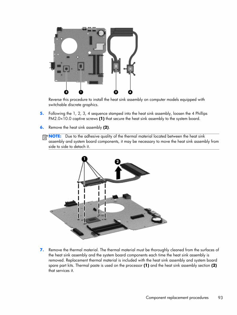
Reverse this procedure to install the heat sink assembly on computer models equipped withswitchable discrete graphics.
5. Following the 1, 2, 3, 4 sequence stamped into the heat sink assembly, loosen the 4 PhillipsPM2.0×10.0 captive screws (1) that secure the heat sink assembly to the system board.
6. Remove the heat sink assembly (2).
NOTE: Due to the adhesive quality of the thermal material located between the heat sinkassembly and system board components, it may be necessary to move the heat sink assembly fromside to side to detach it.
7. Remove the thermal material. The thermal material must be thoroughly cleaned from the surfaces ofthe heat sink assembly and the system board components each time the heat sink assembly isremoved. Replacement thermal material is included with the heat sink assembly and system boardspare part kits. Thermal paste is used on the processor (1) and the heat sink assembly section (2)that services it.
Component replacement procedures 93

Reverse this procedure to install the heat sink assembly on computer models equipped with UMAgraphics.
94 Chapter 6 Removal and replacement procedures for Authorized Service Provider parts

Power connector cable
Description Spare part number
Power connector cable (includes bracket) 732067-001
Before removing the power connector cable, follow these steps:
1. Turn off the computer. If you are unsure whether the computer is off or in Hibernation, turnthe computer on, and then shut it down through the operating system.
2. Disconnect the power from the computer by unplugging the power cord from the computer.
3. Disconnect all external devices from the computer.
4. Remove the battery (see Battery on page 49), and then remove the following components:
a. Optical drive (see Optical drive on page 55)
b. WLAN module (see WLAN module on page 53)
c. Memory module (see Memory module on page 51)
d. Keyboard (see Keyboard on page 62)
e. Top cover (see Top cover on page 67)
f. Hard drive (see Hard drive on page 71)
g. System board (see System board on page 80)
Remove the power connector board:
NOTE: The power connector bracket was removed when removing the system board.
1. Turn the system board upside down, with the front toward you.
Component replacement procedures 95

2. Release the power connector from the clip built into the system board.
Reverse this procedure to install the power connector cable.
96 Chapter 6 Removal and replacement procedures for Authorized Service Provider parts

Speakers
Description Spare part number
Speakers (include subwoofer, speaker cable, and rubber isolators) 734422-001
Before removing the speakers, follow these steps:
1. Turn off the computer. If you are unsure whether the computer is off or in Hibernation, turnthe computer on, and then shut it down through the operating system.
2. Disconnect the power from the computer by unplugging the power cord from the computer.
3. Disconnect all external devices from the computer.
4. Remove the battery (see Battery on page 49), and then remove the following components:
a. Optical drive (see Optical drive on page 55)
b. WLAN module (see WLAN module on page 53)
c. Memory module (see Memory module on page 51)
d. Keyboard (see Keyboard on page 62)
e. Top cover (see Top cover on page 67)
f. Hard drive (see Hard drive on page 71)
g. System board (see System board on page 80)
Remove the speakers:
Component replacement procedures 97

▲ Remove the speakers by lifting up on the clip on the right side speaker and lifting the speakers.Carefully and gently lift the speaker wire connecting the left and right speakers.
NOTE: The speaker connection cable was removed when removing the system board.
NOTE: The speakers include rubber isolators that are installed in the screw holes. These isolatorsare crucial to the performance of the speakers.
Reverse this procedure to install the speakers.
Display assembly
Display assembly:
35.56 cm (14.0 in), high definition (HD), WLED, SVA BrightView flat display assembly for use with HP Pavilion Notebooks.This display assembly is spared at the subcomponent level only.
35.56 cm (14.0 in), high definition (HD), WLED, SVA BrightView TouchSmart slim display assembly for use with HP PavilionTouchSmart Notebooks:
● Aluminum with midnight black 734414-001
● Flyer red 734410-001
● Goji berry 736814-001
● Hazel berry 736815-001
● Mineral black 736813-001
98 Chapter 6 Removal and replacement procedures for Authorized Service Provider parts

● Pearl white 734409-001
● Raspberry 736816-001
● Regal purple 734412-001
● Revolutionary blue 734411-001
● Silver 734413-001
Before removing the display assembly, follow these steps:
1. Turn off the computer. If you are unsure whether the computer is off or in Hibernation, turnthe computer on, and then shut it down through the operating system.
2. Disconnect the power from the computer by unplugging the power cord from the computer.
3. Disconnect all external devices from the computer.
4. Remove the battery (see Battery on page 49), and then remove the following components:
a. Optical drive (see Optical drive on page 55)
b. WLAN module (see WLAN module on page 53)
c. Memory module (see Memory module on page 51)
d. Keyboard (see Keyboard on page 62)
e. Top cover (see Top cover on page 67)
f. Hard drive (see Hard drive on page 71)
g. System board (see System board on page 80)
Remove the display assembly:
1. Remove the 5 Phillips PM2.5×6.5 screws (1) that secure the display assembly tothe base enclosure.
Component replacement procedures 99

2. Remove the display assembly (2).
NOTE: For instructions on removing the display assembly subcomponents for a HP Pavilion notebookflat display model, see Display assembly subcomponents on page 30.
Reverse this procedure to install the display assembly.
100 Chapter 6 Removal and replacement procedures for Authorized Service Provider parts

Display assembly subcomponents
NOTE: These procedures are for replacing the display assembly internal components for the HPPavilion flat display models only.
Component Spare part number
Webcamera/microphone module (includes adhesive and screws) 725665-001
Display panel cable (includes webcamera/microphone module cable andscrews)
734407-001
Antenna Kit (includes left and right wireless antenna cables and transceiversand 2 rubber screws)
734400-001
Display Hinge Kit (includes left and right hinges and rubber screws) 734408-001
Display back cover (includes 2 rubber screws):
Aluminum with midnight black finish 734405-001
Flyer red finish 734401-001
Goji berry finish 736810-001
Hazel berry finish 736811-001
Mineral black finish 736809-001
Pearl white finish 726193-001
Raspberry finish 736812-001
Regal purple finish 734403-001
Revolutionary blue finish 734402-001
Silver finish 734404-001
Before removing the display assembly subcomponents, follow these steps:
1. Turn off the computer. If you are unsure whether the computer is off or in Hibernation, turnthe computer on, and then shut it down through the operating system.
2. Disconnect the power from the computer by unplugging the power cord from the computer.
3. Disconnect all external devices from the computer.
4. Remove the battery (see Battery on page 49), and then remove the following components:
a. Optical drive (see Optical drive on page 55)
b. WLAN module (see WLAN module on page 53)
c. Memory module (see Memory module on page 51)
d. Keyboard (see Keyboard on page 62)
e. Top cover (see Top cover on page 67)
Component replacement procedures 101

f. Hard drive (see Hard drive on page 71)
g. System board (see System board on page 80)
5. Remove the display panel (see Display panel on page 59).
6. Remove the display assembly (see Display assembly on page 98).
Remove the display assembly subcomponents:
1. If it is necessary to replace the webcamera/microphone module:
a. Disconnect the webcamera/microphone module cable (1) from the webcamera/microphonemodule. (The webcamera/microphone module cable is part of the display panel cable.)
b. Detach the webcamera/microphone module (2) from the display back cover.)
2. If it is necessary to replace the hinges:
a. Remove the two top screws (1) and two bottom screws (2) from the display hinges.
b. Remove the display hinge covers (2).
102 Chapter 6 Removal and replacement procedures for Authorized Service Provider parts

c. Remove the hinges (3) from the display enclosure.
3. If it is necessary to replace the display panel cable:
a. Release the display panel cable from the clips (1) and routing channel built into thedisplay enclosure.
b. Carefully release the cable from the channel guides (2), and remove the display panel cable(3).
4. If it is necessary to replace the wireless antenna cables and transceivers:
a. Release the wireless antenna transceivers (1) from the display back cover. (The wirelessantenna transceivers are attached to the display back cover with double-sided tape.)
b. Release the wireless antenna cables from the clips (2) built into the display back cover.
Component replacement procedures 103

c. Remove the wireless antenna cables and transceivers (3).
Reverse this procedure to install the display assembly subcomponents.
104 Chapter 6 Removal and replacement procedures for Authorized Service Provider parts

7 Windows 8 – Using Setup Utility(BIOS) and HP PC HardwareDiagnostics (UEFI)
Setup Utility, or Basic Input/Output System (BIOS), controls communication between all the input andoutput devices on the system (such as disk drives, display, keyboard, mouse, and printer). Setup Utility(BIOS) includes settings for the types of devices installed, the startup sequence of the computer, and theamount of system and extended memory.
Starting Setup Utility (BIOS)To start Setup Utility (BIOS), turn on or restart the computer, quickly press esc, and then press f10.
NOTE: Use extreme care when making changes in Setup Utility (BIOS). Errors can prevent thecomputer from operating properly.
Updating the BIOSUpdated versions of the BIOS may be available on the HP website.
Most BIOS updates on the HP website are packaged in compressed files called SoftPaqs.
Some download packages contain a file named Readme.txt, which contains information regardinginstalling and troubleshooting the file.
Determining the BIOS version
To determine whether available BIOS updates contain later BIOS versions than those currently installedon the computer, you need to know the version of the system BIOS currently installed.
BIOS version information (also known as ROM date and System BIOS) can be revealed by pressing fn+esc (if you are already in Windows) or by using Setup Utility (BIOS).
1. Start Setup Utility (BIOS) (see Starting Setup Utility (BIOS) on page 105).
2. Use the arrow keys to select Main.
Starting Setup Utility (BIOS) 105

3. To exit Setup Utility (BIOS) without saving your changes, use the arrow keys to select Exit, selectExit Discarding Changes, and then press enter.
4. Select Yes.
Downloading a BIOS update
CAUTION: To reduce the risk of damage to the computer or an unsuccessful installation, downloadand install a BIOS update only when the computer is connected to reliable external power using the ACadapter. Do not download or install a BIOS update while the computer is running on battery power,docked in an optional docking device, or connected to an optional power source. During thedownload and installation, follow these instructions:
Do not disconnect power from the computer by unplugging the power cord from the AC outlet.
Do not shut down the computer or initiate Sleep.
Do not insert, remove, connect, or disconnect any device, cable, or cord.
1. From the Start screen, type support, and then select the HP Support Assistant app.
2. Click Updates and tune-ups, and then click Check for HP updates now.
3. Follow the on-screen instructions.
4. At the download area, follow these steps:
a. Identify the most recent BIOS update and compare it to the BIOS version currently installed onyour computer. If the update is more recent than your BIOS, make a note of the date, name,or other identifier. You may need this information to locate the update later, after it has beendownloaded to your hard drive.
b. Follow the on-screen instructions to download your selection to the hard drive.
If the update is more recent than your BIOS, make a note of the path to the location on yourhard drive where the BIOS update is downloaded. You will need to access this path whenyou are ready to install the update.
NOTE: If you connect your computer to a network, consult the network administrator beforeinstalling any software updates, especially system BIOS updates.
BIOS installation procedures vary. Follow any instructions that are revealed on the screen after thedownload is complete. If no instructions are revealed, follow these steps:
1. From the Start screen, type e, and then select File Explorer.
2. Click your hard drive designation. The hard drive designation is typically Local Disk (C:).
3. Using the hard drive path you recorded earlier, open the folder on your hard drive that containsthe update.
4. Double-click the file that has an .exe extension (for example, filename.exe).
The BIOS installation begins.
5. Complete the installation by following the on-screen instructions.
106 Chapter 7 Windows 8 – Using Setup Utility (BIOS) and HP PC Hardware Diagnostics (UEFI)

NOTE: After a message on the screen reports a successful installation, you can delete thedownloaded file from your hard drive.
Using HP PC Hardware Diagnostics (UEFI)HP PC Hardware Diagnostics is a Unified Extensible Firmware Interface (UEFI) that allows you to rundiagnostic tests to determine whether the computer hardware is functioning properly. The tool runsoutside the operating system so that it can isolate hardware failures from issues that are caused by theoperating system or other software components.
To start HP PC Hardware Diagnostics UEFI:
1. Turn on or restart the computer, quickly press esc, and then press f2.
The BIOS searches three places for the HP PC Hardware Diagnostics (UEFI) tools in the followingorder:
a. Connected USB drive
NOTE: To download the HP PC Hardware Diagnostics (UEFI) tool to a USB drive, seeDownloading HP PC Hardware Diagnostics (UEFI) to a USB device on page 107.
b. Hard drive
c. BIOS
2. Click the type of diagnostic test you want to run, and then follow the on-screen instructions.
NOTE: If you need to stop a diagnostic test, press esc.
Downloading HP PC Hardware Diagnostics (UEFI) to a USB device
NOTE: The HP PC Hardware Diagnostics (UEFI) download instructions are provided in English only.
1. Go to http://www.hp.com.
2. Click Support & Drivers, and then click the Drivers & Software tab.
3. Enter the product name in the text box, and then click Search.
4. Select your computer model, and then select your operating system.
5. In the Diagnostic section, click HP UEFI Support Environment.
– or –
Click Download, and then select Run.
Using HP PC Hardware Diagnostics (UEFI) 107

8 Ubuntu Linux – Using Setup Utility(BIOS) and System Diagnostics
Setup Utility, or Basic Input/Output System (BIOS), controls communication between all the input andoutput devices on the system (such as disk drives, display, keyboard, mouse, and printer). Setup Utilityincludes settings for the types of peripherals installed, the startup sequence of the computer, and theamount of system and extended memory.
NOTE: Use extreme care when making changes in Setup Utility. Errors can prevent the computer fromoperating properly.
Starting Setup Utility▲ Turn on or restart the computer. While the computer is booting press esc. When the Startup menu
is displayed, press f10.
Using Setup Utility
Changing the language of Setup Utility
1. Start Setup Utility.
2. Use the arrow keys to select System Configuration > Language, and then press enter.
3. Use the arrow keys to select a language, and then press enter.
4. When a confirmation prompt with your language selected is displayed, press enter.
5. To save your change and exit Setup Utility, use the arrow keys to select Exit > Exit SavingChanges, and then press enter.
Your change takes effect immediately.
108 Chapter 8 Ubuntu Linux – Using Setup Utility (BIOS) and System Diagnostics

Navigating and selecting in Setup Utility
Setup Utility does not support the TouchPad. Navigation and selection are by keystroke.
● To choose a menu or a menu item, use the arrow keys.
● To choose an item in a list or to toggle a field—for example an Enable/Disable field—use eitherthe arrow keys or f5 and f6.
● To select an item, press enter.
● To close a text box or return to the menu display, press esc.
● To display additional navigation and selection information while Setup Utility is open, press f1.
Displaying system information
1. Start Setup Utility.
2. Select the Main menu. System information such as the system time and date, and identificationinformation about the computer is displayed.
3. To exit Setup Utility without changing any settings, use the arrow keys to select Exit > ExitDiscarding Changes, and then press enter.
Restoring factory default settings in Setup Utility
1. Start Setup Utility.
2. Use the arrow keys to select Exit > Load Setup Defaults, and then press enter.
3. When the Setup Confirmation is displayed, press enter.
4. To save your change and exit Setup Utility, use the arrow keys to select Exit > Exit SavingChanges, and then press enter.
The Setup Utility factory settings take effect when the computer restarts.
NOTE: Your password, security, and language settings are not changed when you restore the factorysettings.
Exiting Setup Utility
● To exit Setup Utility and save your changes from the current session:
If the Setup Utility menus are not visible, press esc to return to the menu display. Then use thearrow keys to select Exit > Exit Saving Changes, and then press enter.
● To exit Setup Utility without saving your changes from the current session:
If the Setup Utility menus are not visible, press esc to return to the menu display. Then use thearrow keys to select Exit > Exit Discarding Changes, and then press enter.
Using Setup Utility 109

Updating the BIOSUpdated versions of the BIOS may be available on the HP website.
Most BIOS updates on the HP website are packaged in compressed files called SoftPaqs.
Some download packages contain a file named Readme.txt, which contains information regardinginstalling and troubleshooting the file.
Determining the BIOS version
To determine whether available BIOS updates contain later BIOS versions than those currently installedon the computer, you need to know the version of the system BIOS currently installed.
BIOS version information (also known as ROM date and System BIOS) can be displayed by usingSetup Utility.
1. Start Setup Utility.
2. If the system information is not displayed, use the arrow keys to select the Main menu.
BIOS and other system information is displayed.
3. To exit Setup Utility, use the arrow keys to select Exit > Exit Discarding Changes, and thenpress enter.
Downloading a BIOS update
CAUTION: To reduce the risk of damage to the computer or an unsuccessful installation, downloadand install a BIOS update only when the computer is connected to reliable external power using the ACadapter. Do not download or install a BIOS update while the computer is running on battery power, orconnected to an optional power source. During the download and installation, follow these instructions:
Do not disconnect power from the computer by unplugging the power cord from the AC outlet.
Do not shut down the computer or initiate Suspend or Hibernation.
Do not insert, remove, connect, or disconnect any device, cable, or cord.
1. Access the page on the HP website that provides software for your computer.
2. Follow the on-screen instructions to identify your computer and access the BIOS update you wantto download.
3. At the download area, follow these steps:
a. Identify the BIOS update that is later than the BIOS version currently installed on yourcomputer. Make a note of the date, name, or other identifier. You may need this informationto locate the update later, after it has been downloaded to your hard drive.
b. Follow the on-screen instructions to download your selection to the hard drive.
Make a note of the path to the location on your hard drive where the BIOS update isdownloaded. You will need to access this path when you are ready to install the update.
110 Chapter 8 Ubuntu Linux – Using Setup Utility (BIOS) and System Diagnostics
NOTE: If you connect your computer to a network, consult the network administrator beforeinstalling any software updates, especially system BIOS updates.
BIOS installation procedures vary. Follow any instructions that are displayed on the screen after thedownload is complete.
NOTE: After a message on the screen reports a successful installation, you can delete thedownloaded file from your hard drive.
Using Advanced System DiagnosticsAdvanced System Diagnostics allows you to run diagnostic tests to determine if the computer hardwareis functioning properly. The following diagnostic tests are available in Advanced System Diagnostics:
● Start-up test—This test analyzes the main computer components that are required to start thecomputer.
● Run-in test—This test repeats the start-up test and checks for intermittent problems that the start-uptest does not detect.
● Hard disk test—This test analyzes the physical condition of the hard drive, and then checks alldata in every sector of the hard drive. If the test detects a damaged sector, it attempts to move thedata to a good sector.
● Memory test—This test analyzes the physical condition of the memory modules. If it reports anerror, replace the memory modules immediately.
● Battery test—This test analyzes the condition of the battery and calibrates the battery if necessary.If the battery fails the test, contact support to report the issue and purchase a replacement battery.
● System Tune-Up—This group of additional tests checks your computer to make sure that the maincomponents are functioning correctly. System Tune-Up runs longer and more comprehensive testson memory modules, hard drive SMART attributes, the hard drive surface, the battery (and batterycalibration), video memory, and the WLAN module status.
You can view system information and error logs in the Advanced System Diagnostics window.
To start Advanced System Diagnostics:
1. Turn on or restart the computer. While the computer is booting press esc. When the Startup menuis displayed, press f2.
2. Click the diagnostic test you want to run, and then follow the on-screen instructions.
NOTE: If you need to stop a diagnostics test while it is running, press esc.
Using Advanced System Diagnostics 111

9 Specifications
Computer specifications
Metric U.S.
Dimensions:
Width 34.70 cm 13.67 in
Depth ≤ 23.90 cm ≤ 9.42 in
Height ≤ 2.30 cm ≤ .91 in
Weight:
For TouchSmart computer models with Intel processors 2.10 kg 4.61 lbs
For computer models with flat display panels and Intelprocessors
2.03 kg 4.48 lbs
For TouchSmart computer models with AMD processors 2.07 kg 4.56 lbs
For computer models with flat display panels and AMDprocessors
2.01 kg 4.42 lbs
Input power
Operating voltage and current 19.5 V dc @ 3.33 A – 65 W
19.5 V dc @ 4.62 A – 90 W
Temperature
Operating (writing to optical disc) 5°C to 35°C 41°F to 95°F
Nonoperating -20°C to 60°C -4°F to 140°F
Relative humidity
Operating 10% to 90%
Nonoperating 5% to 95%
Maximum altitude (unpressurized)
Operating (14.7 to 10.1 psia) -15 m to 3,048 m -50 ft to 10,000 ft
Nonoperating (14.7 to 4.4 psia) -15 m to 12,192 m -50 ft to 40,000 ft
Shock
112 Chapter 9 Specifications

Metric U.S.
Operating 125 g, 2 ms, half-sine
Nonoperating 200 g, 2 ms, half-sine
Random vibration
Operating 0.75 g zero-to-peak, 10 Hz to 500 Hz, 0.25 oct/min sweep rate
Nonoperating 1.50 g zero-to-peak, 10 Hz to 500 Hz, 0.5 oct/min sweep rate
NOTE: Applicable product safety standards specify thermal limits for plastic surfaces. The computer operates well within thisrange of temperatures.
35.56 cm (14.0 in), display specifications
Metric U.S.
Dimensions
Width 32.4 cm 12.8 in
Height 19.3 cm 7.6 in
Diagonal 35.56 cm 14.0 in
Number of colors 262K (6 bit)
Contrast ratio 500:1 (typical)
Brightness 200 cd/m2 (nits) (typical)
Backlight WLED
Total power consumption 3.2 W (max)
Viewing angle ±45° horizontal, +15° up & -35° down vertical (typical)
35.56 cm (14.0 in), display specifications 113

Hard drive specifications
1 TB* 750 GB* 500 GB*
Dimensions
Height 9.5 mm 9.5 mm 7 mm
Width 70 mm 70 mm 70 mm
Weight 107 g max 107 g max 107 g max
Interface type SATA SATA SATA
Transfer rate 300 MB/sec 300 MB/sec 300 MB/sec
Security ATA security ATA security ATA security
Seek times (typical read, including setting)
Single track 1.5 ms 1.0 ms 1.5 ms
Average 11.0 ms 14.0 ms 12.0 ms
Maximum 22.0 ms 24.0 ms 22.0 ms
Logical blocks 1,953,525,168 1,465,128,359 976,752,240
Disk rotational speed 5400 rpm 7200 and 5400rpm
7200 and 5400 rpm
Operating temperature 5°C to 55°C (41°F to 131°F)
*Size refers to hard drive storage capacity. Actual accessible capacity is less. Actual drive specifications may differ slightly.
NOTE: Certain restrictions and exclusions apply. Contact support for details.
114 Chapter 9 Specifications

DVD±RW SuperMulti Double-Layer CombinationDrive specifications
Applicable disc
Read CD-DA, CD+(E)G, CD-MIDI, CD-TEXT, CD-ROM, CD-ROM XA, MIXEDMODE CD, CD-I, CD-I Bridge (Photo-CD, Video CD), Multisession CD (Photo-CD, CD-EXTRA, Portfolio, CD-R, CD-RW), CD-R, CD-RW, DVD-ROM (DVD-5,DVD-9, DVD-10, DVD-18), DVD-R, DVD-RW, DVD+R, DVD+RW, DVD-RAM
Write CD-R and CD-RW, DVD+R, DVD+RW, DVD-R, DVD-RW, DVD-RAM
Random access time
DVD < 230 ms
CD < 175 ms
Cache buffer 2 MB
Data transfer rate
24X CD-ROM 3,600 KB/sec
8X DVD-ROM 10,800 KB/sec
24X CD-R 3,600 KB/sec
16X CD-RW 2,400 KB/sec
8X DVD+R 10,800 KB/sec
4X DVD+RW 5,400 KB/sec
8X DVD-R 10,800 KB/sec
4X DVD-RW 5,400 KB/sec
2.4X DVD+R(9) 2,700 KB/sec
5X DVD-RAM 6,750 KB/sec
Transfer mode Multiword DMA Mode
DVD±RW SuperMulti Double-Layer Combination Drive specifications 115

10 Windows 8 – Backing up, restoring,and recovering
Your computer includes tools provided by HP and Windows to help you safeguard your informationand retrieve it if you ever need to. These tools will help you return your computer to a proper workingstate or even back to the original factory state, all with simple steps.
This chapter provides information about the following processes:
● Creating recovery media and backups
● Restoring and recovering your system
NOTE: This chapter describes an overview of backing up, restoring and recovering options. For moredetails about the tools provided, see Help and Support. From the Start screen, type help, and thenselect Help and Support.
116 Chapter 10 Windows 8 – Backing up, restoring, and recovering

Creating recovery media and backups1. After you successfully set up the computer, create HP Recovery media. This step creates a backup
of the HP Recovery partition on the computer. The backup can be used to reinstall the originaloperating system in cases where the hard drive is corrupted or has been replaced.
HP Recovery media you create will provide the following recovery options:
● System Recovery—Reinstalls the original operating system and the programs that wereinstalled at the factory.
● Minimized Image Recovery—Reinstalls the operating system and all hardware-related driversand software, but not other software applications.
● Factory Reset—Restores the computer to the state its original factory state by deleting allinformation from the hard drive and re-creating the partitions. Then it reinstalls the operatingsystem and the software that was installed at the factory.
See Creating HP Recovery media on page 117.
2. Use the Windows tools to create system restore points and create backups of personalinformation. For more information and steps, see Windows Help and Support. From the Startscreen, type help, and then select Help and Support.
Creating HP Recovery media
HP Recovery Manager is a software program that offers a way to create recovery media after yousuccessfully set up the computer. HP Recovery media can be used to perform system recovery if thehard drive becomes corrupted. System recovery reinstalls the original operating system and thesoftware programs installed at the factory, and then configures the settings for the programs. HPRecovery media can also be used to customize the system or restore the factory image if you replacethe hard drive.
● Only one set of HP Recovery media can be created. Handle these recovery tools carefully, andkeep them in a safe place.
● HP Recovery Manager examines the computer and determines the required storage capacity forthe blank USB flash drive or the number of blank DVD discs that will be required.
● To create recovery discs, your computer must have an optical drive with DVD writer capability,and you must use only high-quality blank DVD-R, DVD+R, DVD-R DL, DVD+R DL discs. Do not userewritable discs such as CD±RW, DVD±RW, double-layer DVD±RW, or BD-RE (rewritable Blu-ray)discs; they are not compatible with HP Recovery Manager software. Or instead you can use ahigh-quality blank USB flash drive.
● If your computer does not include an integrated optical drive with DVD writer capability, but youwould like to create DVD recovery media, you can use an external optical drive (purchasedseparately) to create recovery discs, or you can obtain recovery discs for your computer from theHP website. For U.S. support, go to http://www.hp.com/go/contactHP. For worldwide support,go to http://welcome.hp.com/country/us/en/wwcontact_us.html. If you use an external opticaldrive, it must be connected directly to a USB port on the computer; the drive cannot be connectedto a USB port on an external device, such as a USB hub.
Creating recovery media and backups 117

● Be sure that the computer is connected to AC power before you begin creating the recoverymedia.
● The creation process can take up to an hour or more. Do not interrupt the creation process.
● If necessary, you can exit the program before you have finished creating all of the recovery DVDs.HP Recovery Manager will finish burning the current DVD. The next time you start HP RecoveryManager, you will be prompted to continue, and the remaining discs will be burned.
To create HP Recovery media:
1. From the Start screen, type recovery, and then select HP Recovery Manager.
2. Select Recovery Media Creation, and follow the on-screen instructions to continue.
If you ever need to recover the system, see Recovering using HP Recovery Manager on page 119.
118 Chapter 10 Windows 8 – Backing up, restoring, and recovering
Restore and recoveryThere are several options for recovering your system. Choose the method that best matches yoursituation and level of expertise:
● Windows offers several options for restoring from backup, refreshing the computer, and resettingthe computer to its original state. For more information and steps, see Help and Support. From theStart screen, type help, and then select Help and Support.
● If you need to correct a problem with a preinstalled application or driver, use the Drivers andApplications Reinstall option of HP Recovery Manager to reinstall the individual application ordriver.
From the Start screen, type recovery, select HP Recovery Manager, and then select Driversand Applications Reinstall, and follow the on-screen instructions.
● If you want to reset your computer using a minimized image, you can choose the HP MinimizedImage Recovery option from the HP Recovery partition or HP Recovery media. Minimized ImageRecovery installs only drivers and hardware-enabling applications. Other applications included inthe image continue to be available for installation through the Drivers and Applications Reinstalloption in HP Recovery Manager.
For more information, see Recovering using HP Recovery Manager on page 119.
● If you want to recover the computer's original factory partitioning and content, you can choose theSystem Recovery option from the HP Recovery media. For more information, see Recovering usingHP Recovery Manager on page 119.
● If you have replaced the hard drive, you can use the Factory Reset option of HP Recovery media torestore the factory image to the replacement drive. For more information, see Recovering using HPRecovery Manager on page 119.
● If you wish to remove the recovery partition to reclaim hard drive space, HP Recovery Manageroffers the Remove Recovery Partition option.
For more information, see Removing the HP Recovery partition on page 121.
Recovering using HP Recovery Manager
HP Recovery Manager software allows you to recover the computer to its original factory state. Usingthe HP Recovery media you created, you can choose from one of the following recovery options:
● System Recovery—Reinstalls the original operating system, and then configures the settings for theprograms that were installed at the factory.
● Minimized Image Recovery—Reinstalls the operating system and all hardware-related drivers andsoftware, but not other software applications.
● Factory Reset—Restores the computer to the state its original factory state by deleting allinformation from the hard drive and re-creating the partitions. Then it reinstalls the operatingsystem and the software that was installed at the factory.
The HP Recovery partition allows Minimized Image Recovery.
Restore and recovery 119

What you need to know
● HP Recovery Manager recovers only software that was installed at the factory. For software notprovided with this computer, you must either download the software from the manufacturer'swebsite or reinstall the software from the media provided by the manufacturer.
● Recovery through HP Recovery Manager should be used as a final attempt to correct computerissues.
● HP Recovery media must be used if the computer hard drive fails.
● To use the Factory Reset or System Recovery options, you must use HP Recovery media.
● If the HP Recovery media do not work, you can obtain recovery media for your system from the HPwebsite. For U.S. support, go to http://www.hp.com/go/contactHP. For worldwide support, goto http://welcome.hp.com/country/us/en/wwcontact_us.html.
IMPORTANT: HP Recovery Manager does not automatically provide backups of your personal data.Before beginning recovery, back up any personal data you wish to retain.
Using the HP Recovery partition to recover a minimized image
The HP Recovery partition allows you to perform a minimized image recovery without the need forrecovery discs or a recovery USB flash drive. This type of recovery can only be used if the hard drive isstill working.
To start HP Recovery Manager from the HP Recovery partition:
1. Press f11 while the computer boots.
– or –
Press and hold f11 as you press the power button.
2. Select Troubleshoot from the boot options menu.
3. Select HP Recovery Manager, and follow the on-screen instructions.
120 Chapter 10 Windows 8 – Backing up, restoring, and recovering

Using HP Recovery media to recover
You can use HP Recovery media to recover the original system. This method can be used if your systemdoes not have an HP Recovery partition or if the hard drive is not working properly.
1. If possible, back up all personal files.
2. Insert the first HP Recovery disc you created into the optical drive on your computer or into anoptional external optical drive, and then restart the computer.
– or –
Insert the HP Recovery USB flash drive you created into a USB port on your computer, and thenrestart the computer.
NOTE: If the computer does not automatically restart in HP Recovery Manager, change thecomputer boot order. See Changing the computer boot order on page 121.
3. Follow the on-screen instructions.
Changing the computer boot order
If computer does not restart in HP Recovery Manager, you can change the computer boot order, whichis the order of devices listed in BIOS where the computer looks for startup information. You can changethe selection for an optical drive or a USB flash drive.
To change the boot order:
1. Insert the HP Recovery media you created.
2. Restart the computer.
3. Press and hold esc while the computer is restarting, and then press f9 for boot options.
4. Select the optical drive or USB flash drive you want to boot from.
5. Follow the on-screen instructions.
Removing the HP Recovery partition
HP Recovery Manager software allows you to remove the HP Recovery partition to free up hard drivespace.
IMPORTANT: Removing the HP Recovery partition means you can no longer use Windows Refresh,the Windows Remove everything and reinstall Windows option, or the HP Recovery Manager optionfor minimized image recovery. Create HP Recovery media before removing the Recovery partition toensure you have recovery options; see Creating HP Recovery media on page 117.
Follow these steps to remove the HP Recovery partition:
1. From the Start screen, type recovery, and then select HP Recovery Manager.
2. Select Remove Recovery Partition, and follow the on-screen instructions to continue.
Restore and recovery 121

11 Ubuntu Linux – Backing up,restoring, and recovering
Recovery after a system failure is as good as your most recent backup. As you add new software anddata files, you should continue to back up your system on a regular basis to maintain a reasonablycurrent backup.
Performing a system recoveryThe Deja Dup Restore Tool allows you to repair or restore the computer to its original factory state. Youcan create an image restore DVD using an optional external DVD±RW optical drive. You can alsocreate a restore image on a USB storage device.
CAUTION: Using Restore completely erases hard drive contents and reformats the hard drive. Allfiles you have created and any software installed on the computer are permanently removed. Therecovery tool reinstalls the original operating system and programs and drivers that were installed atthe factory. Software, drivers, and updates not installed at the factory must be manually reinstalled.Personal files must be restored from a backup.
NOTE: HP recommends that you create the image restore in the event of a system failure.
Creating the restore DVDs
The restore creation software creates a set of system restore discs using blank, writable DVDs (DVD-R orDVD+R). HP recommends using blank DVD+R discs from a manufacturer you trust, because theserecovery DVDs are so important. You need approximately 3 blank DVD+R discs. The program stateshow many discs are needed at the beginning of the process.
To create restore DVDs:
1. Click the System menu icon at the far right of the top panel, and then click System Settings> Backup.
2. Select Storage from the panel on the left side of the window, click the down-arrow next toBackup Location, and select the DVD from the drop-down list.
3. Select Overview from the panel on the left side of the window, and then click Back Up Now.
4. Follow the on-screen instructions.
122 Chapter 11 Ubuntu Linux – Backing up, restoring, and recovering

Creating a restore image on a USB device
NOTE: Be sure AC power is connected to the computer you begin.
Verify the exact amount of free space on your storage device before you begin the creation process.For most models, you will need at least 8 GB of free space on the storage device. However, dependingon the drivers and software installed on your computer, you may need slightly more than 8 GB ofspace. HP recommends that you use a 16 GB device or above for best results.
IMPORTANT: Remember to insert your USB device into the USB port on the computer before startingthis procedure.
To create the restore image:
1. Click the System menu icon at the far right of the top panel, and then click System Settings> Backup.
2. Select Storage from the panel on the left side of the window, click the down-arrow next toBackup location, and select the USB device from the drop-down list.
NOTE: If the USB device is not listed in the drop-down list for Backup Location, select LocalFolder, and then click the Choose Folder button. Select the USB device from the panel on theleft side of the Choose Folder window, and click OK.
3. Select Overview from the panel on the left side of the window, and then click Backup Now.
4. Follow the on-screen instructions.
Performing recovery using the restore media
NOTE: The following procedure uses the F11 BIOS Recovery feature to perform the recovery.
1. If possible, back up all personal files.
2. Shut down the computer.
3. Be sure the restore DVD or USB device is connected to the computer.
4. Restart the computer.
5. Using the arrow keys, select Recovery, and then press enter.
6. Follow the on-screen instructions.
NOTE: If you are unable to boot (start up) your computer with the primary operating system, and youdid not create a system recovery disc, you must purchase an Ubuntu Operating System DVD to reinstallthe operating system. For additional information, refer to the Worldwide Telephone Numbers bookletfor more information.
Performing a system recovery 123

Backing up your informationYou should back up your computer files on a regular schedule to maintain a current backup. You canmanually back up your information to an optional external drive, a network drive, discs, or the UbuntuOne website. Back up your system at the following times:
● At regularly scheduled times
● Before the computer is repaired or restored
● Before you add or modify hardware or software
To back up your home directory files to the Ubuntu website using the Deja Dup Backup Tool:
NOTE: Before you back up your information, be sure you have designated a location to save thebackup files.
1. Click the System menu icon at the far right of the top panel, and then click System Settings> Backup icon.
2. Select Folders from the panel on the left side of the window, and beneath Folders to back up,select the folders to back up.
3. Select Storage from the panel on the left side of the window, click the down-arrow next toBackup Location, and select Ubuntu One from the drop-down list.
4. Select Overview from the panel on the left side of the window, and then click Back Up Now.
NOTE: The first time you backup your files to Ubuntu One, you will need to create an account tosign into Ubuntu One. Enter your email address and password into the account sign-in boxes andfollow the on-screen instructions to complete the sign-in process.
To restore backup files:
1. Click the System menu icon at the far right of the top panel, and then click System Settings> Backup icon.
2. Click Restore, select the location of the backup files and the folder name, and then clickForward.
3. Under Restore from When?, select the date of the files to be restored and click Forward.
4. Select the location and folder where the files are to be restored and click Forward.
5. Follow the on-line instructions.
6. Click Restore to start restoring the files, or click Cancel to cancel the operation.
NOTE: You may also back up to cloud storage services provided by various companies. For a smallfee, they will keep your backup for you. A cloud service is recommended since it is an easy way tokeep your backups off-site and safe from any disaster.
124 Chapter 11 Ubuntu Linux – Backing up, restoring, and recovering

12 Power cord set requirements
The wide-range input feature of the computer permits it to operate from any line voltage from 100 to120 V ac, or from 220 to 240 V ac.
The 3-conductor power cord set included with the computer meets the requirements for use in thecountry or region where the equipment is purchased.
Power cord sets for use in other countries or regions must meet the requirements of the country andregion where the computer is used.
Requirements for all countriesThe following requirements are applicable to all countries and regions:
● The length of the power cord set must be at least 1.0 m (3.3 ft) and no more than 2.0 m (6.5 ft).
● All power cord sets must be approved by an acceptable accredited agency responsible forevaluation in the country or region where the power cord set will be used.
● The power cord sets must have a minimum current capacity of 10 A and a nominal voltage ratingof 125 or 250 V ac, as required by the power system of each country or region.
● The appliance coupler must meet the mechanical configuration of an EN 60 320/IEC 320Standard Sheet C13 connector for mating with the appliance inlet on the back of the computer.
Requirements for all countries 125

Requirements for specific countries and regions
Country/region Accredited agency Applicable note number
Argentina IRAM 1
Australia SAA 1
Austria OVE 1
Belgium CEBEC 1
Brazil ABNT 1
Canada CSA 2
Chile IMQ 1
Denmark DEMKO 1
Finland FIMKO 1
France UTE 1
Germany VDE 1
India ISI 1
Israel SII 1
Italy IMQ 1
Japan JIS 3
The Netherlands KEMA 1
New Zealand SANZ 1
Norway NEMKO 1
The People's Republic of China CCC 4
Saudi Arabia SASO 7
Singapore PSB 1
South Africa SABS 1
South Korea KTL 5
Sweden SEMKO 1
Switzerland SEV 1
Taiwan BSMI 6
Thailand TISI 1
The United Kingdom ASTA 1
126 Chapter 12 Power cord set requirements
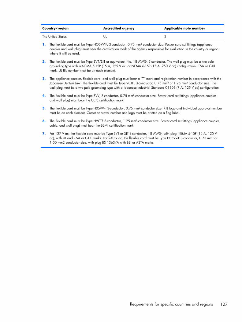
Country/region Accredited agency Applicable note number
The United States UL 2
1. The flexible cord must be Type HO5VV-F, 3-conductor, 0.75 mm² conductor size. Power cord set fittings (appliancecoupler and wall plug) must bear the certification mark of the agency responsible for evaluation in the country or regionwhere it will be used.
2. The flexible cord must be Type SVT/SJT or equivalent, No. 18 AWG, 3-conductor. The wall plug must be a two-polegrounding type with a NEMA 5-15P (15 A, 125 V ac) or NEMA 6-15P (15 A, 250 V ac) configuration. CSA or C-ULmark. UL file number must be on each element.
3. The appliance coupler, flexible cord, and wall plug must bear a “T” mark and registration number in accordance with theJapanese Dentori Law. The flexible cord must be Type VCTF, 3-conductor, 0.75 mm² or 1.25 mm² conductor size. Thewall plug must be a two-pole grounding type with a Japanese Industrial Standard C8303 (7 A, 125 V ac) configuration.
4. The flexible cord must be Type RVV, 3-conductor, 0.75 mm² conductor size. Power cord set fittings (appliance couplerand wall plug) must bear the CCC certification mark.
5. The flexible cord must be Type H05VV-F 3-conductor, 0.75 mm² conductor size. KTL logo and individual approval numbermust be on each element. Corset approval number and logo must be printed on a flag label.
6. The flexible cord must be Type HVCTF 3-conductor, 1.25 mm² conductor size. Power cord set fittings (appliance coupler,cable, and wall plug) must bear the BSMI certification mark.
7. For 127 V ac, the flexible cord must be Type SVT or SJT 3-conductor, 18 AWG, with plug NEMA 5-15P (15 A, 125 Vac), with UL and CSA or C-UL marks. For 240 V ac, the flexible cord must be Type H05VV-F 3-conductor, 0.75 mm² or1.00 mm2 conductor size, with plug BS 1363/A with BSI or ASTA marks.
Requirements for specific countries and regions 127

13 Recycling
When a non-rechargeable or rechargeable battery has reached the end of its useful life, do not disposeof the battery in general household waste. Follow the local laws and regulations in your area forbattery disposal.
HP encourages customers to recycle used electronic hardware, HP original print cartridges,and rechargeable batteries. For more information about recycling programs, see the HP Web site athttp://www.hp.com/recycle.
128 Chapter 13 Recycling

Index
AAC adapter
identifying 10light 10support 5
AC adapter, spare part numbers31, 35
action keysidentifying 16
adapter, HDMI to VGA 32, 35Advanced System Diagnostics
using for Ubuntu Linux computermodels 111
antennaremoval 103spare part number 30, 35,
101Antenna Kit, spare part number
30, 35, 101audio, product description 4audio-in (microphone) jacks 8audio-out (headphone) jacks 8
Bbackups
for Ubuntu Linux computermodels 122
for Windows 8 computermodels 116
personal information for UbuntuLinux computer models 124
base enclosure, spare partnumber 29, 36
batteryremoval 49spare part number 29, 35, 49
battery cover, identifying 17battery lock latch, identifying 17battery release latch 17
BIOSdetermining version for Ubuntu
Linux computer models 110determining version for
Windows computer models105
downloading an update forUbuntu Linux computermodels 110
downloading an update forWindows computer models106
updating for Ubuntu Linuxcomputer models 110
updating for Windows computermodels 105
Bluetooth label 20boot order
changing HP Recovery Managerfor Windows 8 computermodels 121
bottom 20buttons
left TouchPad 13power 15right TouchPad 13
Ccaps lock light, identifying 14chipset, product description 2components
bottom 17display 12left side 10right side 8top 13
computer major components 21computer specifications 112connector, power 10
Ddefault settings, restoring for
Ubuntu Linux computer models109
deleted filesrestoring for Windows 8
computer models 119display assembly
removal 98spare part numbers 38, 39,
98, 101subcomponents 30
display assembly subcomponentsremoval 101
display assembly, spare partnumbers 36
display back coverspare part number 35spare part numbers 35, 36,
38display back cover, spare part
numbers 30, 36, 101display bezel
removal 59spare part number 30, 40, 60
display hingeremoval 102spare part number 30, 36,
101Display Hinge Kit, spare part
number 30, 36, 101display panel
36product description 3spare part number 30
display panel cableremoval 103spare part number 30, 36,
101, 103
Index 129
display specifications 113DVD±RW and CD-RW SuperMulti
Double-Layer Combination Drive,specifications 115
DVD±RW Double-Layer SuperMultiDrive
spare part number 36
Eesc key, identifying 16Ethernet, product description 4
Ffactory settings, restoring for
Ubuntu Linux computer models109
fanremoval 89spare part numbers 35, 89
fn key, identifying 16
Ggraphics, product description 2
Hhard drive
product description 4removal 71spare part numbers 25, 33,
34, 35, 71specifications 114
hard drive cable, removing 86hard drive connector cable
illustrated 33Hard Drive Hardware Kit
contents 33spare part number 25, 33,
42, 71hard drive light, identifying 8hard drive rubber bracket
illustrated 33removal 74
HDMI portidentifying 10
HDMI to VGA adapter, spare partnumber 32, 35
heat sinkspare part numbers 38
heat sink assemblyremoval 91spare part numbers 28, 91
HP PC Hardware Diagnostics (UEFI)downloading for Windows
computer models 107using on Windows computer
models 107HP Recovery Manager
correcting boot problems forWindows 8 computermodels 121
for Windows 8 computermodels 119
starting for Windows 8computer models 120
HP Recovery mediacreating for Windows 8
computer models 117recovery for Windows 8
computer models 121HP Recovery partition
for Windows 8 computermodels 120
recovery for Windows 8computer models 120
removing for Windows 8computer models 121
Iintegrated webcam, identifying
12internal microphones, identifying
12
Jjacks
audio-in (microphone) 8audio-out (headphone) 8network 10RJ-45 (network) 10
Kkeyboard
product description 5removal 62spare part numbers 23, 40,
41, 42, 62keys
action 16esc 16fn 16Windows 16
Llabels
Bluetooth 20regulatory 20serial number 19service 19wireless certification 20WLAN 20
latch, battery release 17lights
AC adapter 10caps lock 14hard drive 8mute 14network 10power 8, 14RJ-45 (network) 10wireless 14
Mmemory card reader, identifying
11memory module
identifying 18product description 3removal 51spare part numbers 28, 35,
51microphone
product description 4minimized image
creating for Windows 8computer models 119
minimized image recoveryfor Windows 8 computer
models 120model name 1mSATA solid-state drive
spare part number 35mute light, identifying 14
Nnetwork jack, identifying 10network lights, identifying 10
Ooperating system, product
description 6Optical drive
removal 55spare part number 55
130 Index

optical driveproduct description 4removal 55spare part number 33, 36spare part numbers 55specifications 115
optical drive bracketremoval 56
optical drive connector cableremoval 78spare part number 78
optical drive, identifying 9optical drive, spare part number
29original system recovery
for Windows 8 computermodels 119
PPlastics Kit, spare part number
29, 36, 50pointing device, product
description 5ports
HDMI 10product description 5USB 2.0 8USB 3.0 11
power button boardremoval 75spare part number 25, 36, 75
power button, identifying 15power connector cable
removal 95spare part number 28, 35, 95
power connector, identifying 10power cord
requirements for all countries125
requirements for specificcountries and regions 126
set requirements 125spare part numbers 31, 34
power lights, identifying 8, 14power requirements, product
description 5processor
product description 1product description
audio 4
chipset 2display panel 3Ethernet 4external media cards 5graphics 2hard drive 4keyboard 5memory module 3microphone 4operating system 6optical drive 4pointing device 5ports 5power requirements 5processors 1product name 1security 6serviceability 6video 4wireless 4
product name 1product name and number,
computer 19
Rrecovery
discs for Windows 8 computermodels 117, 121
for Windows 8 computermodels 119
HP Recovery Manager forWindows 8 computermodels 119
media for Windows 8 computermodels 121
starting for Windows 8computer models 120
supported discs for Windows 8computer models 117
USB flash drive for Windows 8computer models 121
using HP Recovery media forWindows 8 computermodels 118
recovery mediacreating for Windows 8
computer models 117creating using HP Recovery
Manager for Windows 8computer models 118
recovery partitionfor Windows 8 computer
models 120removing for Windows 8
computer models 121regulatory information
regulatory label 20wireless certification labels 20
removal/replacementprocedures 48, 58
restorerecovery for Ubuntu Linux
computer models 123Windows File History 119
restore DVDsfor Ubuntu Linux computer
models 122restore USB device
for Ubuntu Linux computermodels 123
RJ-45 (network) jack lights,identifying 10
RJ-45 (network) jack, identifying10
RTC batteryremoval 87spare part number 28, 35, 87
SScrew Kit, spare part number 32,
36security cable slot, identifying 10security, product description 6serial number 19serial number, computer 19service door
identifying 18removal 50spare part number 36, 50
service door, spare part number29
service labelslocating 19
serviceability, product description6
Setup Utilitychanging the language for
Ubuntu Linux computermodels 108
Index 131

displaying system informationfor Ubuntu Linux computermodels 109
exiting for Ubuntu Linuxcomputer models 109
navigating for Ubuntu Linuxcomputer models 109
restoring default settings forUbuntu Linux computermodels 109
selecting for Ubuntu Linuxcomputer models 109
starting for Ubuntu Linuxcomputer models 108
Setup Utility (BIOS), using 105slots
memory card reader 11security cable 10
speakersidentifying 15removal 97spare part number 29, 36, 97
specificationscomputer 112display 113DVD±RW and CD-RW
SuperMulti Double-LayerCombination Drive 115
hard drive 114optical drive 115
SuperMulti DVD+/-RW Double-Layer Drive
spare part number 33SuperMulti DVD±R/RW Double-
Layer Drivespare part number 29, 55
supported discsrecovery for Windows 8
computer models 117system board
removal 80spare part numbers 25, 27,
36, 37, 38, 39, 40, 80, 82system information, displaying for
Ubuntu Linux computer models109
system recoveryfor Ubuntu Linux computer
models 122for Windows 8 computer
models 119system restore point
creating for Windows 8computer models 117
Ttop cover
removal 67spare part numbers 24, 37,
67TouchPad
buttons 13TouchPad button board
removal 77spare part number 25, 36, 77
TouchPad zone, identifying 13traveling with the computer 20
UUSB 2.0 ports, identifying 8USB 3.0 ports identifying 11USB/audio board
removing 72spare part number 25, 72
USB/audio board,spare part number 36
Vvents, identifying 10, 18video, product description 4
Wwebcam light, identifying 12webcamera/microphone module
removal 102spare part number 30, 35,
101, 102Windows
File History 119restoring files 119system restore point 117
Windows key, identifying 16wireless antenna
removal 103spare part number 30, 35,
101wireless certification label 20
wireless light 14wireless module compartment cover
spare part number 36wireless, product description 4WLAN antennas, identifying 12WLAN device 20WLAN label 20WLAN module
removal 53spare part numbers 28, 53
WLAN, spare part numbers 35
132 Index