hp pavilion 11 notebook pc hp pavilion touchsmart 11...
TRANSCRIPT

HP Pavilion 11 Notebook PCHP Pavilion TouchSmart 11 NotebookPCHP 215 G1 Notebook PC
Maintenance and Service Guide

© Copyright 2013 Hewlett-PackardDevelopment Company, L.P.
AMD, the AMD Arrow logo, andcombinations thereof, are trademarks ofAdvanced Micro Devices, Inc. Bluetooth isa trademark owned by its proprietor andused by Hewlett-Packard Company underlicense. Microsoft and Windows are U.S.registered trademarks of the Microsoftgroup of companies. SD Logo is atrademark of its proprietor.
The information contained herein is subjectto change without notice. The onlywarranties for HP products and services areset forth in the express warranty statementsaccompanying such products and services.Nothing herein should be construed asconstituting an additional warranty. HP shallnot be liable for technical or editorial errorsor omissions contained herein.
Product notice
This guide describes features that arecommon to most models. Some featuresmay not be available on your computer.
Not all features are available in all editionsof Windows 8. This computer may requireupgraded and/or separately purchasedhardware, drivers, and/or software to takefull advantage of Windows 8 functionality.See for http://www.microsoft.com details.
This computer may require upgraded and/or separately purchased hardware and/or aDVD drive to install the Windows 7 softwareand take full advantage of Windows 7functionality. Seehttp://windows.microsoft.com/en-us/windows7/get-know-windows-7 for details.
First Edition: November 2013
Document Part Number: 742265-001

Important Notice about Customer Self-Repair Parts
CAUTION: Your computer includes Customer Self-Repair parts and parts that should only beaccessed by an authorized service provider. See Chapter 5, "Removal and replacement proceduresfor Customer Self-Repair parts," for details. Accessing parts described in Chapter 6, "Removal andreplacement procedures for Authorized Service Provider only parts," can damage the computer orvoid your warranty.
iii

iv Important Notice about Customer Self-Repair Parts

Safety warning notice
WARNING! To reduce the possibility of heat-related injuries or of overheating the device, do notplace the device directly on your lap or obstruct the device air vents. Use the device only on a hard,flat surface. Do not allow another hard surface, such as an adjoining optional printer, or a softsurface, such as pillows or rugs or clothing, to block airflow. Also, do not allow the AC adapter tocontact the skin or a soft surface, such as pillows or rugs or clothing, during operation. The deviceand the AC adapter comply with the user-accessible surface temperature limits defined bythe International Standard for Safety of Information Technology Equipment (IEC 60950).
v

vi Safety warning notice

Table of contents
1 Product description ........................................................................................................................................ 1
2 External component identification ................................................................................................................ 6
Display .................................................................................................................................................. 6
Buttons and speakers ........................................................................................................................... 7
Keys ..................................................................................................................................................... 8
Lights .................................................................................................................................................... 9
TouchPad ........................................................................................................................................... 10
Left side .............................................................................................................................................. 11
Right side ........................................................................................................................................... 12
Bottom ................................................................................................................................................ 13
Labels ................................................................................................................................................. 13
3 Illustrated parts catalog ............................................................................................................................... 15
Computer major components ............................................................................................................. 15
Display assembly subcomponents ..................................................................................................... 19
Mass storage devices ......................................................................................................................... 20
Miscellaneous parts ............................................................................................................................ 21
Sequential part number listing ............................................................................................................ 21
4 Removal and replacement procedures preliminary requirements ........................................................... 27
Tools required .................................................................................................................................... 27
Service considerations ....................................................................................................................... 27
Plastic parts ....................................................................................................................... 27
Cables and connectors ...................................................................................................... 28
Drive handling .................................................................................................................... 28
Grounding guidelines ......................................................................................................................... 29
Electrostatic discharge damage ......................................................................................... 29
Packaging and transporting guidelines ............................................................. 30
Workstation guidelines ..................................................................... 30
5 Removal and replacement procedures for Customer Self-Repair parts ................................................. 32
Component replacement procedures ................................................................................................. 32
Battery ............................................................................................................................... 33
Service door ....................................................................................................................... 34
Hard drive .......................................................................................................................... 35
vii

WLAN module .................................................................................................................... 37
Memory module ................................................................................................................. 39
6 Removal and replacement procedures for Authorized Service Provider parts ...................................... 40
Component replacement procedures ................................................................................................. 40
RTC battery ....................................................................................................................... 40
Display panel ..................................................................................................................... 42
Display assembly ............................................................................................................... 46
Display assembly subcomponents .................................................................................... 49
Power connector cable ...................................................................................................... 52
Bottom cover ...................................................................................................................... 54
Power button board ........................................................................................................... 56
TouchPad button board ..................................................................................................... 58
Media card reader board ................................................................................................... 60
Fan ..................................................................................................................................... 61
Monitor connector board .................................................................................................... 62
System board ..................................................................................................................... 63
Heat sink ............................................................................................................................ 65
Speakers ............................................................................................................................ 67
7 Using Setup Utility (BIOS) and HP PC Hardware Diagnostics (UEFI) ...................................................... 69
Starting Setup Utility (BIOS) ............................................................................................................... 69
Updating the BIOS ............................................................................................................................. 69
Determining the BIOS version ........................................................................................... 69
Downloading a BIOS update ............................................................................................. 70
Downloading a Windows 8.1 BIOS update ....................................................... 70
Downloading a Windows 7 BIOS update .......................................................... 71
Using HP PC Hardware Diagnostics (UEFI) (select models only) ..................................................... 71
Downloading HP PC Hardware Diagnostics (UEFI) to a USB device ............................... 72
8 Specifications ................................................................................................................................................ 73
Computer specifications ..................................................................................................................... 73
Hard drive specifications .................................................................................................................... 73
9 Windows 7 – Backing up, restoring, and recovering ................................................................................ 75
Creating backups ............................................................................................................................... 75
Creating recovery media to recover the original system .................................................... 75
What you need to know ..................................................................................... 75
Creating the recovery media ............................................................ 76
Creating system restore points .......................................................................................... 76
viii

What you need to know ..................................................................................... 76
Creating a system restore point ........................................................................ 76
Backing up system and personal information .................................................................... 76
Tips for a successful backup ............................................................................. 77
What you need to know ..................................................................................... 77
Creating a backup using Windows Backup and Restore .................................. 77
Restore and recovery ......................................................................................................................... 78
Restoring to a previous system restore point .................................................................... 78
Restoring specific files ....................................................................................................... 78
Restoring specific files using Windows Backup and Restore ............................ 78
Recovering the original system using HP Recovery Manager ........................................... 78
What you need to know ..................................................................................... 78
Recovering using HP Recovery partition (select models only) ......................... 79
Recovering using the recovery media ............................................................... 79
Changing the computer boot order ................................................... 80
10 Windows 8.1 – Backing up, restoring, and recovering ........................................................................... 81
Creating recovery media and backups ............................................................................................... 81
Creating HP Recovery media ............................................................................................ 81
Restore and recovery ......................................................................................................................... 82
Recovering using HP Recovery Manager .......................................................................... 83
What you need to know ..................................................................................... 83
Using the HP Recovery partition ....................................................................... 83
Using HP Recovery media to recover ............................................................... 84
Changing the computer boot order ................................................................... 84
Removing the HP Recovery partition ................................................................................. 84
11 Power cord set requirements .................................................................................................................... 86
Requirements for all countries ............................................................................................................ 86
Requirements for specific countries and regions ............................................................................... 87
12 Recycling ..................................................................................................................................................... 89
Index ................................................................................................................................................................... 90
ix

x

1 Product description
Category Description HP PavilionTouchSmart 11Notebook PC/ HPPavilion 11Notebook PC
HP 215 G1Notebook PC
Product Name HP PavilionTouchSmart 11Notebook PC
HP Pavilion 11Notebook PC
HP 215 G1Notebook PC
Processor ● AMD® A6-1450 1.4 GHz (turbo)/1.0 GHz processor(2.0 MB L2 cache, DDR3L, 1066 MHz, quad core, 8W, with dynamic configurable TDP 15 W)
● AMD A4-1250 1.0 GHz processor (1.0 MB L2cache, DDR3L, 1333 MHz, dual core, 8 W)
√ √
Chipset AMD system on chip (SoC) fusion controller hub (FCH)integrated in accelerated processing unit (APU)
√ √
Graphics Internal graphics:
● AMD Radeon™ HD 8250 Graphics on computermodels equipped with an AMD A6-1450 processor
● AMD Radeon HD 8210 Graphics on computermodels equipped with an AMD A4-1250 processor
Support for DX11, HD decode, and HDMI
√ √
Panel ● 11.6 in (29.5 cm) (1366×768), high-definition (HD),white light emitting diode (WLED), AntiGlare,TouchSmart touchscreen with MultiTouch enabled;16:9 standard viewing angle; typical brightness: 200cd/m2 (nits); flat (3.6 mm), for computer models withWindows 8.1
Supports low-voltage differential signaling (LVDS)
√ √
● 11.6 in (29.5 cm) (1366×768), HD, WLED,AntiGlare; 16:9 standard viewing angle; typicalbrightness: 200 cd/m2 (nits), non-touchscreen, flat(3.6 mm), for computer models with Windows 7
√
1

Category Description HP PavilionTouchSmart 11Notebook PC/ HPPavilion 11Notebook PC
HP 215 G1Notebook PC
Memory One customer-accessible/upgradable memory moduleslot
Supports:
● 1333 MHz at 1.35 V single channel (DDR3L, 1600MHz downgrade to 1333 MHz) for use withA4-1250 processors
● 1066 MHz at 1.35 V single channel (DDR3L, 1600MHz downgrade to 1066 MHz) for use withA6-1450 processors
Support for up to 8192 MB of system RAM in thefollowing configurations:
● 8192 MB × 1
● 4096 MB × 1
√ √
Hard drive Support for 6.35 cm (2.5 in) hard drives in 7.0 mm (.28in) thickness
Support for Serial ATA
Support for HP 3D hard drive protection
Support for the following hard drives:
● 500 GB, 5400 rpm
● 320 GB, 5400 rpm
√ √
Optical drive Support for external DVD±RW Double-Layer withSuperMulti Drive
√
Audio and video Integrated HP TrueVision webcamera: HD (1280×720 by30 frames per second), fixed (no tilt), with activity light
Single digital microphone with appropriate echo-cancellation and noise-suppression software
dts Sound+ (uses Realtek ALC3227-GR audio codec)
Two speakers
√ √
Ethernet Integrated 10/100 network interface card (NIC) √ √
2 Chapter 1 Product description

Category Description HP PavilionTouchSmart 11Notebook PC/ HPPavilion 11Notebook PC
HP 215 G1Notebook PC
Wireless Integrated wireless local area network (WLAN) optionsby way of wireless module
Two WLAN antennas built into display assembly
Support for the following WLAN formats:
● Broadcom BCM943228HMB 802.11 a/b/g/n 2x2WiFi + Bluetooth® 4.0 Combo Adapter
● Qualcomm Atheros AR9485 802.11 b/g/n 1x1WiFi Adapter (select models only)
● Ralink RT3290LE 802.11 b/g/n 1×1 WiFi +Bluetooth 4.0 Combo Adapter
● Realtek RTL8188EE 802.11 b/g/n 1×1WiFi Adapter
√ √
Compatible with Miracast-certified devices (for Windows8.1)
√ √
External mediacards
HP multiformat Micro Digital Media Reader Slot withpush-push technology. Reads data from and writes datato digital memory cards. Supports the following:
● Secure Digital (SD)
● Secure Digital High Capacity (SDHC) Memory Card
● Secure Digital eXtended Capacity (SDXC) MemoryCard
√ √
Ports ● AC adapter: HP Smart pin plug (4.5 mm barrel)
● Audio: one combo audio-out (headphone)/audio in(microphone) jack, supports jack auto-detection
● HDMI: version 1.4, supporting up to 1080p,1920×1080 at 60 Hz
● RJ45/Ethernet
● USB: Two USB 3.0 ports, one USB 2.0 port
● Video: VGA (Dsub 15-pin) supporting 1920×1200external resolution at 60 Hz, hot plug/unplug andauto-detection for correct output to wide-aspectversus standard aspect video
√ √
3

Category Description HP PavilionTouchSmart 11Notebook PC/ HPPavilion 11Notebook PC
HP 215 G1Notebook PC
Keyboard/pointing devices
91%-size, textured, island-style keyboard (no numericalkeypad)
Touchpad requirements:
● 2013 Touchpad
● Taps enabled as default
● PS/2 interface support
● Multi Gestures, with ability to turn on and off
◦ 2-finger scroll
◦ Pinch/zoom
◦ Edge swipe
● Support for Windows 8.1 Modern TouchPadGestures (not supported on Windows 7)
√ √
Powerrequirements
Support for a 3 cell, 36 Wh, 3.20 Ah, Li-ion battery
Support for the following AC adapters:
● 65 W HP Smart AC adapter (non-PFC, 4.5 mm)
√ √
● 45 W HP Smart AC adapter (non-PFC, 4.5 mm)
● 65 W HP Smart AC adapter (MSH, non-PFC, 4.5mm)
√
Security Support for security cable lock √ √
Operating system Preinstalled:
● Windows 8.1 Small Screen Touch
√ √
● Windows 8.1 Professional 64 (for TouchSmartmodels only)
● Windows 7 Professional with Windows 8.1 productactivation key (for non-touchscreen models only)
● Windows 7 Home Premium (for non-touchscreenmodels only)
● Windows 7 Professional 64 (for non-touchscreenmodels only)
√
4 Chapter 1 Product description

Category Description HP PavilionTouchSmart 11Notebook PC/ HPPavilion 11Notebook PC
HP 215 G1Notebook PC
Operating system Web-only support:
● Windows 8.1 Professional 64
● Windows 8.1 Enterprise 64
● Windows 8.1 Multi-Language 64
● Windows 8.1 Emerging Markets 64
● Windows 8.1 Chinese Markets 64
√
Serviceability End user replaceable parts:
● AC adapter
● Battery (system)
● Hard drive
● Memory
● WLAN module
√ √
5

2 External component identification
Display
Item Component Description
(1) Internal display switch Turns off the display and initiates Sleep if the display isclosed while the power is on.
NOTE: The internal display switch is not visible fromthe outside of the computer.
(2) WLAN antennas (2)* Send and receive wireless signals to communicate withwireless local area networks (WLANs).
NOTE: To set up a WLAN and connect to the Internet,you need a broadband modem (either DSL or cable,purchased separately), high-speed Internet servicepurchased from an Internet service provider, and awireless router (purchased separately).
(3) Webcamera light On: The webcamera is in use.
(4) Webcamera Records video, captures still photographs, and providesaccess to video conferences and online chat by meansof streaming video.
(5) Internal microphone Records sound.
*The antennas are not visible from the outside of the computer. For optimal transmission, keep the areas immediatelyaround the antennas free from obstructions. For wireless regulatory notices, see the section of the Regulatory, Safety, andEnvironmental Notices that applies to your country or region.
6 Chapter 2 External component identification

Buttons and speakers
Item Component Description
(1) Power button ● When the computer is off, press the button to turnon the computer.
● When the computer is on, press the button briefly toinitiate Sleep.
● When the computer is in the Sleep state, press thebutton briefly to exit Sleep.
● When the computer is in Hibernation, press thebutton briefly to exit Hibernation.
CAUTION: Pressing and holding down the powerbutton will result in the loss of unsaved information. If thecomputer has stopped responding and MicrosoftWindows shutdown procedures are ineffective, pressand hold the power button down for at least 5 seconds toturn off the computer.
(2) Speakers (2) Produce sound.
Buttons and speakers 7

Keys
Item Component Description
(1) esc key Reveals system information when pressed incombination with the fn key.
(2) fn key Executes frequently used system functions whenpressed in combination with the esc key.
(3) Windows key ● Windows 8–Returns you to the Start screen from anopen app or the Windows desktop.
NOTE: Pressing the Windows key again willreturn you to the previous screen.
● Windows 7–Displays the Windows Start menu.
(4) Action keys Execute frequently used system functions.
8 Chapter 2 External component identification

Lights
Item Component Description
(1) Power light ● On: The computer is on.
● Blinking: The computer is in the Sleep state, apower-saving state. The computer shuts off powerto the display and other unneeded components.
● Off: The computer is off or in Hibernation.Hibernation is a power-saving state that uses theleast amount of power.
(2) Caps lock light On: Caps lock is on, which switches the keys toall capital letters.
(3) Mute light ● Amber: Computer sound is off.
● Off: Computer sound is on.
(4) Wireless light On: An integrated wireless device, such as a WLANdevice and/or a Bluetooth device, is on.
NOTE: On some models, the wireless light is amberwhen all wireless devices are off.
Lights 9

TouchPad
Item Component Description
(1) TouchPad zone Moves the on-screen pointer and selects or activatesitems on the screen.
NOTE: The TouchPad also supports edge-swipegestures.
(2) Left TouchPad button Functions like the left button on an external mouse.
(3) Right TouchPad button Functions like the right button on an external mouse.
10 Chapter 2 External component identification

Left side
Item Component Description
(1) Security cable slot Attaches an optional security cable to the computer.
NOTE: The security cable is designed to act as adeterrent, but it may not prevent the computer frombeing mishandled or stolen.
(2) External monitor port Connects an external VGA monitor or projector.
(3) Vent Enables airflow to cool internal components.
NOTE: The computer fan starts up automatically tocool internal components and prevent overheating. It isnormal for the internal fan to cycle on and off duringroutine operation.
(4) USB 2.0 port Connects an optional USB device.
(5) Memory card reader Reads data from and writes data to memory cards suchas Secure Digital (SD) memory cards.
(6) Hard drive light ● Blinking white: The hard drive is being accessed.
● Amber: HP 3D DriveGuard has temporarily parkedthe hard drive.
(7) Power light ● On: The computer is on.
● Blinking: The computer is in the Sleep state, apower-saving state. The computer shuts off powerto the display and other unneeded components.
● Off: The computer is off or in Hibernation.Hibernation is a power-saving state that uses theleast amount of power.
Left side 11

Right side
Item Component Description
(1) Audio-out (headphone) jack/Audio in(microphone) jack
Connects optional powered stereo speakers,headphones, earbuds, a headset, or a television audiocable. Also connects an optional headset microphone.This jack does not support optional microphone-onlydevices.
WARNING! To reduce the risk of personal injury,adjust the volume before putting on headphones,earbuds, or a headset. For additional safety information,refer to the Regulatory, Safety, and EnvironmentalNotices.
NOTE: When a device is connected to the jack, thecomputer speakers are disabled.
NOTE: Be sure that the device cable has a 4-conductor connector that supports both audio-out(headphone) and audio in (microphone).
(2) USB 3.0 port Connect optional USB devices.
(3) HDMI port Connects an optional video or audio device, such as ahigh-definition television, any compatible digital or audiocomponent, or a high-speed HDMI device.
(4) RJ-45 (network) jack Connects a network cable.
(5) AC adapter light ● White: The AC adapter is connected and thebattery is charged.
● Amber: The AC adapter is connected and thebattery is charging.
● Off: The computer is using battery power.
(6) Power connector Connects an AC adapter.
12 Chapter 2 External component identification

Bottom
Item Component Description
(1) Service door Provides access to the hard drive bay, the WLANmodule slot, and the memory module slot.
CAUTION: To prevent an unresponsive system,replace the wireless module only with a wireless moduleauthorized for use in the computer by the governmentalagency that regulates wireless devices in your country orregion. If you replace the module and then receive awarning message, remove the module to restorecomputer functionality, and then contact support throughHelp and Support.
(2) Battery lock latch Locks the battery into the battery bay.
(3) Battery bay Holds the battery.
(4) Battery release latch Releases the battery from the battery bay.
LabelsThe labels affixed to the computer provide information you may need when you troubleshoot systemproblems or travel internationally with the computer.
IMPORTANT: All labels described in this section will be located in one of 3 places depending onyour computer model: Affixed to the bottom of the computer, located in the battery bay, or under theservice door.
For help finding these locations, refer to Bottom on page 13.
Bottom 13

● Service label—Provides important information to identify your computer. When contactingsupport, you will probably be asked for the serial number, and possibly for the product number orthe model number. Locate these numbers before you contact support.
NOTE: Your service labels will resemble one of the examples shown below. Refer to theillustration that most closely matches the service label on your computer.
Component
(1) Product name
(2) Serial number
(3) Product number
(4) Warranty period
(5) Model number (select models only)
Component
(1) Serial number
(2) Product number
(3) Warranty period
(4) Model number (select models only)
(5) Revision number
● Regulatory label(s)—Provide(s) regulatory information about the computer.
● Wireless certification label(s)—Provide(s) information about optional wireless devices and theapproval markings for the countries or regions in which the devices have been approved for use.
14 Chapter 2 External component identification

3 Illustrated parts catalog
Computer major components
Computer major components 15

Item Component Spare partnumber
HP PavilionTouchSmart 11Notebook PC/HP Pavilion 11Notebook PC
HP 215 G1Notebook PC
(1) 11.6 inch (29.46 cm), AG, SVA, LED TouchSmartdisplay assembly (includes webcamera/microphonemodule and wireless antenna cables)
753948-001 √ √
11.6 inch (29.46 cm), AG, SVA, LED display assembly,non-touchscreen. The display assembly is spared at thesubcomponent level only. For more display assemblyspare part information, see Display assemblysubcomponents on page 19.
√
(2) Keyboard/top cover (includes keyboard cable and TouchPad):
For use in Belgium 730895-A41 √
For use in Bulgaria 730895-BA1 √
For use in Canada 730895-DB1 √
For use in the Czech Republic and Slovakia 730895-FL1 √
For use in Denmark, Finland, and Norway 730895-DH1 √
For use in France 730895-051 √
For use in Germany 730895-041 √
For use in Israel 730895-BB1 √
For use in Japan 730895-291 √
For use in Latin America 730895-161 √
For use in the Netherlands 730895-B31 √
For use in Portugal 730895-131 √
For use in Russia 730895-251 √
For use in Saudi Arabia 730895-171 √
For use in South Korea 730895-AD1 √
For use in Spain 730895-071 √
For use in Switzerland 730895-BG1 √
For use in Taiwan 730895-AB1 √
For use in Thailand 730895-281 √
For use in Turkey 730895-141 √
For use in the United Kingdom and Singapore 730895-031 √
For use in the United States 730895-001 √
For use in the United States 744192-001 √
For use in Latin America 744192-161 √
16 Chapter 3 Illustrated parts catalog

Item Component Spare partnumber
HP PavilionTouchSmart 11Notebook PC/HP Pavilion 11Notebook PC
HP 215 G1Notebook PC
For use in Canada 744192-DB1 √
(3) Power button board (includes cable) 730899-001 √ √
TouchPad button board, includes: 730898-001 √ √
(4a) TouchPad button board (includes TouchPad cable and TouchPad buttonboard cable)
(4b) TouchPad button board bracket
(5) Monitor connector board (includes cable) 730901-001 √ √
(6) Media card reader board (includes cable) 730897-001 √ √
(7) Fan (includes cable and cowling) 730903-001 √ √
(8) System board (includes replacement thermal material):
Equipped with an AMD A4-1250 processor, a graphicssubsystem with UMA memory, for use on computers withWindows 8.1 Standard operating system
744789-501 √
Equipped with an AMD A4-1250 processor, a graphicssubsystem with UMA memory, for use on computers withWindows 7 operating system
744185-001 √
Equipped with an AMD A4-1250 processor, a graphicssubsystem with UMA memory, for use on computers withWindows 8.1 Standard operating system
744185-501 √
Equipped with an AMD A4-1250 processor, a graphicssubsystem with UMA memory, for use on computers withWindows 8.1 Professional operating system
744185-601 √
Equipped with an AMD A6-1450 processor, a graphicssubsystem with UMA memory, for use on computers withWindows 8.1 Standard operating system
744790-501 √
Equipped with an AMD A6-1450 processor, a graphicssubsystem with UMA memory, for use on computers withWindows 7 operating system
744189-001 √
Equipped with an AMD A6-1450 processor, a graphicssubsystem with UMA memory, for use on computers withWindows 8.1 Standard operating system
744189-501 √
Equipped with an AMD A6-1450 processor, a graphicssubsystem with UMA memory, for use on computers withWindows 8.1 Professional operating system
744189-601 √
(9) Heat sink (includes 4 captive screws and replacementthermal material)
730902-001 √ √
(10) Speaker Kit (includes left and right speakers and cables) 730890-001 √ √
(11) Bottom cover (includes left and right corner covers, items13)
Computer major components 17

Item Component Spare partnumber
HP PavilionTouchSmart 11Notebook PC/HP Pavilion 11Notebook PC
HP 215 G1Notebook PC
TouchSmart models 730887-001 √ √
HP 215 G1 Notebook PC non-touchscreen models 747750-001 √
(12) Memory module (PC3L, 12800, 1600 MHz):
8 GB 693374-001 √ √
4 GB 691740-001 √ √
(13) Rear corner covers (2, included with the bottom cover) √ √
(14) WLAN module:
Atheros AR9485 802.11 b/g/n 1x1 WiFi Adapter 675794-001 √ √
Broadcom BCM943228HMB 802.11 a/b/g/n 2x2 WiFi +Bluetooth 4.0 Combo Adapter
730668-001 √ √
Ralink RT3290LE 802.11 b/g/n 1×1 WiFi + Bluetooth4.0 Combo Adapter
690020-001 √ √
Realtek RTL8188EE 802.11 b/g/n 1×1 WiFi Adapter 709848-001 √ √
(15) Power connector cable (includes bracket) 730900-001 √ √
(16) RTC battery (includes cable and double-sided adhesive) 738824-001 √ √
(17) Hard drive (does not include hard drive bracket, hard drive connector cable,or screws):
500 GB, 5400 rpm, 7.0 mm 683802-001 √ √
320 GB, 5400 rpm, 7.0 mm 645193-001 √ √
Hard Drive Hardware Kit (not illustrated, includes harddrive bracket, hard drive connector cable, and screws)
731424-001 √ √
(18) 3 cell, 36 Wh, 3.20 Ah, Li-ion battery 729892-001 √ √
(19) Service door 737253-001 √ √
18 Chapter 3 Illustrated parts catalog
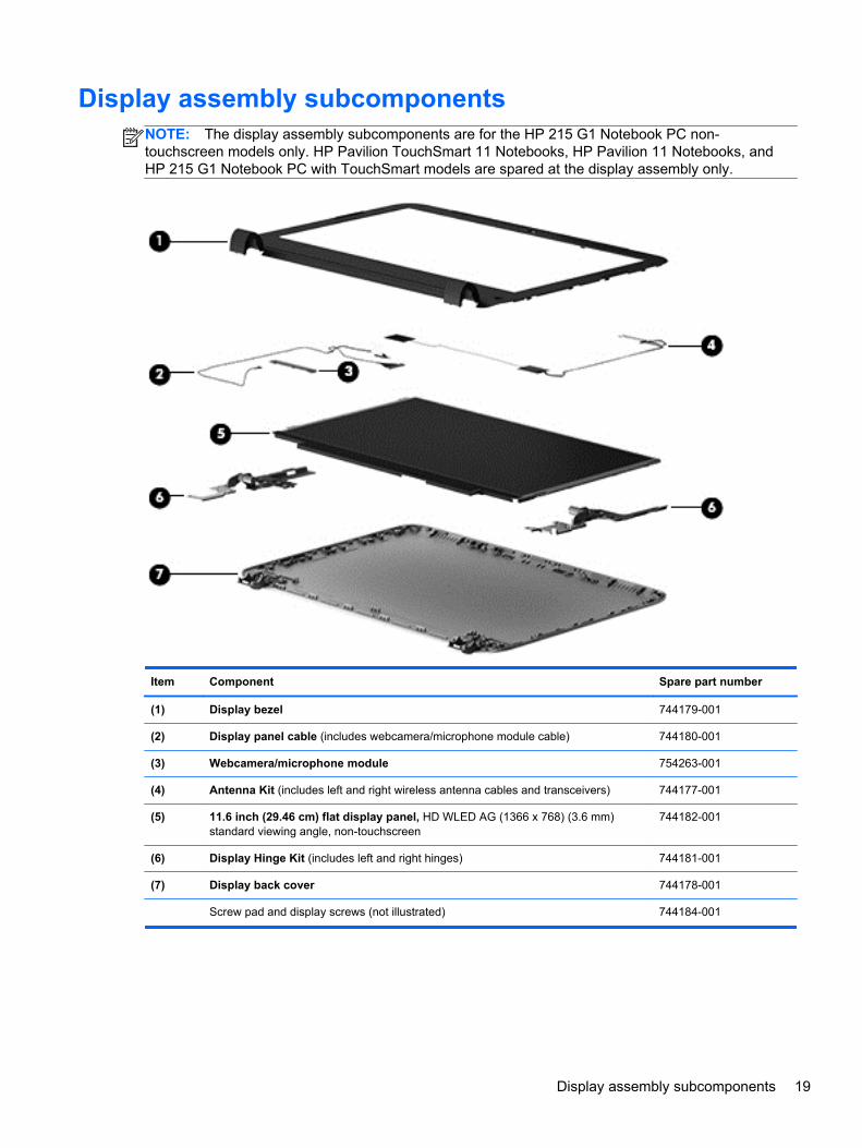
Display assembly subcomponentsNOTE: The display assembly subcomponents are for the HP 215 G1 Notebook PC non-touchscreen models only. HP Pavilion TouchSmart 11 Notebooks, HP Pavilion 11 Notebooks, andHP 215 G1 Notebook PC with TouchSmart models are spared at the display assembly only.
Item Component Spare part number
(1) Display bezel 744179-001
(2) Display panel cable (includes webcamera/microphone module cable) 744180-001
(3) Webcamera/microphone module 754263-001
(4) Antenna Kit (includes left and right wireless antenna cables and transceivers) 744177-001
(5) 11.6 inch (29.46 cm) flat display panel, HD WLED AG (1366 x 768) (3.6 mm)standard viewing angle, non-touchscreen
744182-001
(6) Display Hinge Kit (includes left and right hinges) 744181-001
(7) Display back cover 744178-001
Screw pad and display screws (not illustrated) 744184-001
Display assembly subcomponents 19

Mass storage devices
Item Component Spare partnumber
HP Pavilion 11Notebook PC
HP PavilionTouchSmart 11Notebook PC
HP 215 G1Notebook PC
(1) Hard drive (does not include hard drive bracket, hard drive connector cable,or screws):
500 GB, 5400 rpm, 7.0 mm 683802-001 √ √
320 GB, 5400 rpm, 7.0 mm 645193-001 √ √
Hard Drive Hardware Kit, includes: 731424-001 √ √
(2a) Hard drive bracket
(2b) Hard drive connector cable
Screws (not illustrated)
(3) External DVD±RW Double-Layer with SuperMulti Drive 659940-001 √
20 Chapter 3 Illustrated parts catalog

Miscellaneous parts
Component Spare partnumber
HP Pavilion 11Notebook PC
HP PavilionTouchSmart 11Notebook PC
HP 215 G1Notebook PC
AC adapter
65 W HP Smart AC adapter (non-PFC, 4.5 mm) 710412-001 √ √
65 W HP Smart AC adapter (non-PFC, select models only, 4.5mm)
714657-001 √
45 W HP Smart AC adapter (non-PFC, 4.5 mm) 741727-001 √ √
Power cord (3-pin, black, 1.83 m):
For use in Argentina 490371-D01 √ √
For use in Denmark 490371-081 √
For use in Europe 490371-021 √
For use in Israel 490371-BB1 √
For use in Italy 490371-061 √
For use in Japan 490371-291 √
For use in North America 490371-001 √ √
For use in South Korea 490371-AD1 √
For use in Switzerland 490371-111 √
For use in Taiwan 490371-AB1 √
For use in Thailand 490371-201 √
For use in the United Kingdom and Singapore 490371-031 √
Rubber Feet Kit (includes 2 rear rubber feet) 730888-001 √ √
Screw Kit 730889-001 √ √
Sequential part number listing
Spare partnumber
Description HP Pavilion 11 NotebookPC
HP Pavilion TouchSmart 11Notebook PC
HP 215 G1 Notebook PC
490371-001 Power cord for use in North America (3-pin,black, 1.83 m)
√ √
490371-021 Power cord for use in Europe (3-pin, black,1.83 m)
√
490371-031 Power cord for use in the United Kingdomand Singapore (3-pin, black, 1.83 m)
√
Miscellaneous parts 21

Spare partnumber
Description HP Pavilion 11 NotebookPC
HP Pavilion TouchSmart 11Notebook PC
HP 215 G1 Notebook PC
490371-061 Power cord for use in Italy (3-pin, black,1.83 m)
√
490371-081 Power cord for use in Denmark (3-pin,black, 1.83 m)
√
490371-111 Power cord for use in Switzerland (3-pin,black, 1.83 m)
√
490371-201 Power cord for use in Thailand (3-pin, black,1.83 m)
√
490371-291 Power cord for use in Japan (3-pin, black,1.83 m)
√
490371-AB1 Power cord for use in Taiwan (3-pin, black,1.83 m)
√
490371-AD1 Power cord for use in South Korea (3-pin,black, 1.83 m)
√
490371-BB1 Power cord for use in Israel (3-pin, black,1.83 m)
√
490371-D01 Power cord for use in Argentina (3-pin,black, 1.83 m)
√ √
645193-001 320 GB, 5400 rpm, SATA, 7.0 mm harddrive (does not include hard drive bracket,hard drive connector cable, or screws)
NOTE: The hard drive bracket, hard driveconnector cable, and screws are included inthe Hard Drive Hardware Kit, spare partnumber 731424-001.
√ √
659940-001 External DVD±RW Double-Layer withSuperMulti Drive
√
675794-001 Atheros AR9485 802.11 b/g/n 1x1WiFi Adapter
√ √
683802-001 500 GB, 5400 rpm, SATA, 7.0 mm harddrive (does not include hard drive bracket,hard drive connector cable, or screws)
NOTE: The hard drive bracket, hard driveconnector cable, and screws are included inthe Hard Drive Hardware Kit, spare partnumber 731424-001.
√ √
690020-001 Ralink RT3290LE 802.11 b/g/n 1×1 WiFi +Bluetooth 4.0 Combo Adapter
√ √
691740-001 4 GB memory module (PC3L, 12800, 1600MHz)
√ √
693374-001 8 GB memory module (PC3L, 12800, 1600MHz)
√ √
709848-001 Realtek RTL8188EE 802.11 b/g/n 1×1WiFi Adapter
√ √
22 Chapter 3 Illustrated parts catalog

Spare partnumber
Description HP Pavilion 11 NotebookPC
HP Pavilion TouchSmart 11Notebook PC
HP 215 G1 Notebook PC
710412-001 65 W HP Smart AC adapter (non-PFC, 4.5mm)
√ √
714657-001 65 W HP Smart AC adapter (non-PFC,select models only, 4.5 mm)
√
729892-001 3 cell, 36 Wh, 3.20 Ah, Li-ion battery √ √
730668-001 Broadcom BCM943228HMB 802.11 a/b/g/n2x2 WiFi + Bluetooth 4.0 Combo Adapter
√ √
730887-001 Bottom cover for TouchSmart models(includes left and right corner covers)
√ √
730888-001 Rubber Feet Kit (includes 2 rubber feet) √ √
730889-001 Screw Kit √
730890-001 Speaker Kit (includes left and right speakersand cables)
√ √
730895-001 Keyboard/top cover for usein the United States (includes keyboardcable and TouchPad)
√
730895-031 Keyboard/top cover for usein the United Kingdom and Singapore(includes keyboard cable and TouchPad)
√
730895-041 Keyboard/top cover for use in Germany(includes keyboard cable and TouchPad)
√
730895-051 Keyboard/top cover for use in France(includes keyboard cable and TouchPad)
√
730895-071 Keyboard/top cover for use in Spain(includes keyboard cable and TouchPad)
√
730895-131 Keyboard/top cover for use in Portugal(includes keyboard cable and TouchPad)
√
730895-141 Keyboard/top cover for use in Turkey(includes keyboard cable and TouchPad)
√
730895-161 Keyboard/top cover for use in Latin America(includes keyboard cable and TouchPad)
√
730895-171 Keyboard/top cover for use in Saudi Arabia(includes keyboard cable and TouchPad)
√
730895-251 Keyboard/top cover for use in Russia(includes keyboard cable and TouchPad)
√
730895-281 Keyboard/top cover for use in Thailand(includes keyboard cable and TouchPad)
√
730895-291 Keyboard/top cover for use in Japan(includes keyboard cable and TouchPad)
√
730895-A41 Keyboard/top cover for use in Belgium(includes keyboard cable and TouchPad)
√
Sequential part number listing 23

Spare partnumber
Description HP Pavilion 11 NotebookPC
HP Pavilion TouchSmart 11Notebook PC
HP 215 G1 Notebook PC
730895-AB1 Keyboard/top cover for use in Taiwan(includes keyboard cable and TouchPad)
√
730895-AD1 Keyboard/top cover for use in South Korea(includes keyboard cable and TouchPad)
√
730895-B31 Keyboard/top cover for usein the Netherlands (includes keyboard cableand TouchPad)
√
730895-BA1 Keyboard/top cover for use in Bulgaria(includes keyboard cable and TouchPad)
√
730895-BB1 Keyboard/top cover for use in Israel(includes keyboard cable and TouchPad)
√
730895-BG1 Keyboard/top cover for use in Switzerland(includes keyboard cable and TouchPad)
√
730895-DB1 Keyboard/top cover for use in Canada(includes keyboard cable and TouchPad)
√
730895-DH1 Keyboard/top cover for use in Denmark,Finland, and Norway (includes keyboardcable and TouchPad)
√
730895-FL1 Keyboard/top cover for usein the Czech Republic and Slovakia(includes keyboard cable and TouchPad)
√
730897-001 Media card reader board (includes cable) √ √
730898-001 TouchPad button board (includes bracket,TouchPad cable, and TouchPad buttonboard cable)
√ √
730899-001 Power button board (includes cable) √ √
730900-001 Power connector cable (includes bracket) √ √
730901-001 Monitor connector board (includes cable) √ √
730902-001 Heat sink (includes 4 captive screws andreplacement thermal material)
√ √
730903-001 Fan (includes cable and cowling) √ √
731424-001 Hard Drive Hardware Kit (includes harddrive bracket, hard drive connector cable,and screws)
√ √
737253-001 Service door (includes 2 rubber feet) √ √
738824-001 RTC battery (includes cable and double-sided adhesive)
√ √
741727-001 45 W HP Smart AC adapter (non-PFC, 4.5mm)
√ √
744177-001 Antenna Kit √
744178-001 Display back cover (includes screws) √
24 Chapter 3 Illustrated parts catalog

Spare partnumber
Description HP Pavilion 11 NotebookPC
HP Pavilion TouchSmart 11Notebook PC
HP 215 G1 Notebook PC
744179-001 Display bezel √
744180-001 Display panel cable (includes webcamera/microphone module cable)
√
744181-001 Display Hinge Kit (includes left and righthinges and 2 rubber screws)
√
744182-001 11.6 inch (29.46 cm) flat display panel, HDWLED AG (1366 x 768) (3.6 mm) standardviewing angle, non-touchscreen
√
744183-001 Screw kit √
744184-001 Screw pad and display screws for non-touchscreen models
√
744185-001 System board equipped with an AMDA4-1250 processor, a graphics subsystemwith UMA memory, for use on computerswith Windows 7 operating system (includesreplacement thermal material)
√
744185-501 System board equipped with an AMDA4-1250 processor, a graphics subsystemwith UMA memory, for use on computerswith Windows 8.1 Standard operatingsystem (includes replacement thermalmaterial)
√
744185-601 System board equipped with an AMDA4-1250 processor, a graphics subsystemwith UMA memory, for use on computerswith Windows 8.1 Professional operatingsystem (includes replacement thermalmaterial)
√
744189-001 System board equipped with an AMDA6-1450 processor, a graphics subsystemwith UMA memory, for use on computerswith Windows 7 operating system (includesreplacement thermal material)
√
744189-501 System board equipped with an AMDA6-1450 processor, a graphics subsystemwith UMA memory, for use on computerswith Windows 8.1 Standard operatingsystem (includes replacement thermalmaterial)
√
744189-601 System board equipped with an AMDA6-1450 processor, a graphics subsystemwith UMA memory, for use on computerswith Windows 8.1 Professional operatingsystem (includes replacement thermalmaterial)
√
744192-001 Keyboard/top cover for use in the UnitedStates (includes keyboard cable andTouchPad)
√
Sequential part number listing 25

Spare partnumber
Description HP Pavilion 11 NotebookPC
HP Pavilion TouchSmart 11Notebook PC
HP 215 G1 Notebook PC
744192-161 Keyboard/top cover for use in Latin America(includes keyboard cable and TouchPad)
√
744192-DB1 Keyboard/top cover for use in Canada(includes keyboard cable and TouchPad)
√
744789-501 System board equipped with an AMDA4-1250 processor, a graphics subsystemwith UMA memory, for use on computerswith Windows 8.1 Standard operatingsystem (includes replacement thermalmaterial)
√
744790-501 System board equipped with an AMDA6-1450 processor, a graphics subsystemwith UMA memory, for use on computerswith Windows 8.1 Standard operatingsystem (includes replacement thermalmaterial)
√
747750-001 Bottom cover for HP 215 G1 Notebook PCnon-touchscreen models (includes left andright corner covers)
√
753948-001 11.6 inch (29.46 cm), (AG, SVA, LEDTouchSmart touchscreen display assembly
√ √
754263-001 Webcamera/microphone module for HP 215G1 Notebook PC non-touchscreen models
√
26 Chapter 3 Illustrated parts catalog

4 Removal and replacement procedurespreliminary requirements
Tools requiredYou will need the following tools to complete the removal and replacement procedures:
● Flat-bladed screw driver
● Magnetic screw driver
● Phillips P0 and P1 screw drivers
Service considerationsThe following sections include some of the considerations that you must keep in mind duringdisassembly and assembly procedures.
NOTE: As you remove each subassembly from the computer, place the subassembly (and allaccompanying screws) away from the work area to prevent damage.
Plastic parts
CAUTION: Using excessive force during disassembly and reassembly can damage plastic parts.Use care when handling the plastic parts. Apply pressure only at the points designated in themaintenance instructions.
Tools required 27

Cables and connectors
CAUTION: When servicing the computer, be sure that cables are placed in their proper locationsduring the reassembly process. Improper cable placement can damage the computer.
Cables must be handled with extreme care to avoid damage. Apply only the tension required tounseat or seat the cables during removal and insertion. Handle cables by the connector wheneverpossible. In all cases, avoid bending, twisting, or tearing cables. Be sure that cables are routed insuch a way that they cannot be caught or snagged by parts being removed or replaced. Handle flexcables with extreme care; these cables tear easily.
Drive handling
CAUTION: Drives are fragile components that must be handled with care. To prevent damage tothe computer, damage to a drive, or loss of information, observe these precautions:
Before removing or inserting a hard drive, shut down the computer. If you are unsure whether thecomputer is off or in Hibernation, turn the computer on, and then shut it down through theoperating system.
Before handling a drive, be sure that you are discharged of static electricity. While handling a drive,avoid touching the connector.
Before removing a diskette drive or optical drive, be sure that a diskette or disc is not in the drive andbe sure that the optical drive tray is closed.
Handle drives on surfaces covered with at least one inch of shock-proof foam.
Avoid dropping drives from any height onto any surface.
After removing a hard drive, an optical drive, or a diskette drive, place it in a static-proof bag.
Avoid exposing an internal hard drive to products that have magnetic fields, such as monitorsor speakers.
Avoid exposing a drive to temperature extremes or liquids.
If a drive must be mailed, place the drive in a bubble pack mailer or other suitable form of protectivepackaging and label the package “FRAGILE.”
28 Chapter 4 Removal and replacement procedures preliminary requirements

Grounding guidelines
Electrostatic discharge damage
Electronic components are sensitive to electrostatic discharge (ESD). Circuitry design and structuredetermine the degree of sensitivity. Networks built into many integrated circuits provide someprotection, but in many cases, ESD contains enough power to alter device parameters or meltsilicon junctions.
A discharge of static electricity from a finger or other conductor can destroy static-sensitive devices ormicrocircuitry. Even if the spark is neither felt nor heard, damage may have occurred.
An electronic device exposed to ESD may not be affected at all and can work perfectly throughout anormal cycle. Or the device may function normally for a while, then degrade in the internal layers,reducing its life expectancy.
CAUTION: To prevent damage to the computer when you are removing or installing internalcomponents, observe these precautions:
Keep components in their electrostatic-safe containers until you are ready to install them.
Before touching an electronic component, discharge static electricity by using the guidelinesdescribed in this section.
Avoid touching pins, leads, and circuitry. Handle electronic components as little as possible.
If you remove a component, place it in an electrostatic-safe container.
The following table shows how humidity affects the electrostatic voltage levels generated bydifferent activities.
CAUTION: A product can be degraded by as little as 700 V.
Typical electrostatic voltage levels
Relative humidity
Event 10% 40% 55%
Walking across carpet 35,000 V 15,000 V 7,500 V
Walking across vinyl floor 12,000 V 5,000 V 3,000 V
Motions of bench worker 6,000 V 800 V 400 V
Removing DIPS from plastic tube 2,000 V 700 V 400 V
Removing DIPS from vinyl tray 11,500 V 4,000 V 2,000 V
Removing DIPS from Styrofoam 14,500 V 5,000 V 3,500 V
Removing bubble pack from PCB 26,500 V 20,000 V 7,000 V
Packing PCBs in foam-lined box 21,000 V 11,000 V 5,000 V
Grounding guidelines 29

Packaging and transporting guidelines
Follow these grounding guidelines when packaging and transporting equipment:
● To avoid hand contact, transport products in static-safe tubes, bags, or boxes.
● Protect ESD-sensitive parts and assemblies with conductive or approved containers orpackaging.
● Keep ESD-sensitive parts in their containers until the parts arrive at static-free workstations.
● Place items on a grounded surface before removing items from their containers.
● Always be properly grounded when touching a component or assembly.
● Store reusable ESD-sensitive parts from assemblies in protective packaging ornonconductive foam.
● Use transporters and conveyors made of antistatic belts and roller bushings. Be sure thatmechanized equipment used for moving materials is wired to ground and that proper materialsare selected to avoid static charging. When grounding is not possible, use an ionizer to dissipateelectric charges.
Workstation guidelines
Follow these grounding workstation guidelines:
● Cover the workstation with approved static-shielding material.
● Use a wrist strap connected to a properly grounded work surface and use properly groundedtools and equipment.
● Use conductive field service tools, such as cutters, screw drivers, and vacuums.
● When fixtures must directly contact dissipative surfaces, use fixtures made only of static-safe materials.
● Keep the work area free of nonconductive materials, such as ordinary plastic assembly aidsand Styrofoam.
● Handle ESD-sensitive components, parts, and assemblies by the case or PCM laminate. Handlethese items only at static-free workstations.
● Avoid contact with pins, leads, or circuitry.
● Turn off power and input signals before inserting or removing connectors or test equipment.
30 Chapter 4 Removal and replacement procedures preliminary requirements

Equipment guidelines
Grounding equipment must include either a wrist strap or a foot strap at a grounded workstation.
● When seated, wear a wrist strap connected to a grounded system. Wrist straps are flexiblestraps with a minimum of one megohm ±10% resistance in the ground cords. To provide properground, wear a strap snugly against the skin at all times. On grounded mats with banana-plugconnectors, use alligator clips to connect a wrist strap.
● When standing, use foot straps and a grounded floor mat. Foot straps (heel, toe, or boot straps)can be used at standing workstations and are compatible with most types of shoes or boots. Onconductive floors or dissipative floor mats, use foot straps on both feet with a minimum of onemegohm resistance between the operator and ground. To be effective, the conductive must beworn in contact with the skin.
The following grounding equipment is recommended to prevent electrostatic damage:
● Antistatic tape
● Antistatic smocks, aprons, and sleeve protectors
● Conductive bins and other assembly or soldering aids
● Nonconductive foam
● Conductive tabletop workstations with ground cords of one megohm resistance
● Static-dissipative tables or floor mats with hard ties to the ground
● Field service kits
● Static awareness labels
● Material-handling packages
● Nonconductive plastic bags, tubes, or boxes
● Metal tote boxes
● Electrostatic voltage levels and protective materials
The following table lists the shielding protection provided by antistatic bags and floor mats.
Material Use Voltage protection level
Antistatic plastics Bags 1,500 V
Carbon-loaded plastic Floor mats 7,500 V
Metallized laminate Floor mats 5,000 V
Grounding guidelines 31

5 Removal and replacement proceduresfor Customer Self-Repair parts
NOTE: The Customer Self-Repair program is not available in all locations. Installing a part notsupported by the Customer Self-Repair program may void your warranty. Check your warranty todetermine if Customer Self-Repair is supported in your location.
Component replacement proceduresNOTE: Please read and follow the procedures described here to access and replace CustomerSelf-Repair parts successfully.
NOTE: Details about your computer, including model, serial number, product key, and length ofwarranty, are on the service tag at the bottom of your computer. See Labels on page 13 for details.
This chapter provides removal and replacement procedures for Customer Self-Repair parts.
There are as many as 9 screws that must be removed, replaced, and/or loosened when servicingCustomer Self-Repair parts. Make special note of each screw size and location during removaland replacement.
32 Chapter 5 Removal and replacement procedures for Customer Self-Repair parts

Battery
Description Spare part number
3 cell, 36 Wh, 3.20 Ah, Li-ion battery 729892-001
Before removing the battery, follow these steps:
1. Turn off the computer. If you are unsure whether the computer is off or in Hibernation, turn thecomputer on, and then shut it down through the operating system.
2. Disconnect the power from the computer by unplugging the power cord from the computer.
3. Disconnect all external devices from the computer.
Remove the battery:
WARNING! To reduce potential safety issues, use only the user-replaceable battery provided withthe computer, a replacement battery provided by HP, or a compatible battery purchased from HP.
CAUTION: Removing a user-replaceable battery that is the sole power source for the computer cancause loss of information. To prevent loss of information, save your work or shut down the computerthrough Windows before removing the battery.
1. Turn the computer upside down on a flat surface.
2. Position the computer with the rear toward you.
3. Slide the battery lock latch (1) to the unlocked position.
NOTE: The battery lock latch automatically returns to its original position when the batteryis removed.
4. Slide the battery release latch (2) to release the battery.
5. Remove the battery (3).
Reverse this procedure to install the battery.
Component replacement procedures 33

Service door
Description Spare part number
Service door 737253-001
Before removing the service door, follow these steps:
1. Turn off the computer. If you are unsure whether the computer is off or in Hibernation, turn thecomputer on, and then shut it down through the operating system.
2. Disconnect the power from the computer by unplugging the power cord from the computer.
3. Disconnect all external devices from the computer.
4. Remove the battery (see Battery on page 33).
Remove the service door:
1. Lift up on the rear edge of the service door (1) until the left and right sides detach fromthe computer.
2. Remove the service door (2).
Reverse this procedure to install the service door.
34 Chapter 5 Removal and replacement procedures for Customer Self-Repair parts
Hard drive
NOTE: The hard drive spare part kit does not include the hard drive bracket, hard drive connectorcable, and screws. These components are included in the Hard Drive Hardware Kit, spare partnumber 731424-001.
Description Spare part number
500 GB, 5400 rpm, 7.0 mm 683802-001
320 GB, 5400 rpm, 7.0 mm 645193-001
Before removing the hard drive, follow these steps:
1. Turn off the computer. If you are unsure whether the computer is off or in Hibernation, turn thecomputer on, and then shut it down through the operating system.
2. Disconnect the power from the computer by unplugging the power cord from the computer.
3. Disconnect all external devices from the computer.
4. Remove the battery (see Battery on page 33).
5. Remove the service door (see Service door on page 34).
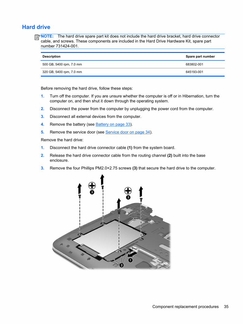
Remove the hard drive:
1. Disconnect the hard drive connector cable (1) from the system board.
2. Release the hard drive connector cable from the routing channel (2) built into the baseenclosure.
3. Remove the four Phillips PM2.0×2.75 screws (3) that secure the hard drive to the computer.
Component replacement procedures 35

4. Remove the hard drive.
5. If it is necessary to disassemble the hard drive, perform the following steps:
a. Position the hard drive with the connector toward you.
b. Disconnect the hard drive connector cable (1) from the hard drive.
c. Remove the four Phillips PM3.0×3.25 screws (2) that secure the hard drive bracket to thehard drive.
d. Remove the hard drive bracket (3) from the hard drive.
The hard drive bracket, hard drive connector cable, and screws are available in the HardDrive Hardware Kit, spare part number 731424-001.
Reverse this procedure to install the hard drive.
36 Chapter 5 Removal and replacement procedures for Customer Self-Repair parts

WLAN module
Description Spare part number
Atheros AR9485 802.11 b/g/n 1x1 WiFi Adapter 675794-001
Broadcom BCM943228HMB 802.11 a/b/g/n 2x2 WiFi + Bluetooth 4.0 Combo Adapter 730668-001
Ralink RT3290LE 802.11 b/g/n 1×1 WiFi + Bluetooth 4.0 Combo Adapter 690020-001
Realtek RTL8188EE 802.11 b/g/n 1×1 WiFi Adapter 709848-001
CAUTION: To prevent an unresponsive system, replace the wireless module only with a wirelessmodule authorized for use in the computer by the governmental agency that regulates wirelessdevices in your country or region. If you replace the module and then receive a warning message,remove the module to restore device functionality, and then contact technical support.
Before removing the WLAN module, follow these steps:
1. Turn off the computer. If you are unsure whether the computer is off or in Hibernation, turn thecomputer on, and then shut it down through the operating system.
2. Disconnect the power from the computer by unplugging the power cord from the computer.
3. Disconnect all external devices from the computer.
4. Remove the battery (see Battery on page 33).
5. Remove the service door (see Service door on page 34).
Remove the WLAN module:
1. Disconnect the WLAN antenna cables (1) from the terminals on the WLAN module.
NOTE: The WLAN antenna cable labeled “1” connects to the WLAN module “Main” terminallabeled “1”. The WLAN antenna cable labeled “2” connects to the WLAN module “Aux” terminallabeled “2”.
2. Remove the Phillips PM2.0×3.5 screw (2) that secures the WLAN module to the system board.(The WLAN module tilts up.)
Component replacement procedures 37

3. Remove the WLAN module (3) by pulling the module away from the slot at an angle.
NOTE: If the WLAN antenna cables are not connected to the terminals on the WLAN module, theprotective sleeves must be installed on the antenna connectors, as shown in the following illustration.
Reverse this procedure to install the WLAN module.
38 Chapter 5 Removal and replacement procedures for Customer Self-Repair parts

Memory module
Description Spare part number
8 GB (PC3L, 12800, 1600 MHz) 693374-001
4 GB (PC3L, 12800, 1600 MHz) 691740-001
Update BIOS before adding memory modules
Before adding new memory, make sure you update the computer to the latest BIOS.
CAUTION: Failure to update the computer to the latest BIOS prior to installing new memory mayresult in various system problems.
To update BIOS, refer to Updating the BIOS on page 69.
Before removing a memory module, follow these steps:
1. Turn off the computer. If you are unsure whether the computer is off or in Hibernation, turn thecomputer on, and then shut it down through the operating system.
2. Disconnect the power from the computer by unplugging the power cord from the computer.
3. Disconnect all external devices from the computer.
4. Remove the battery (see Battery on page 33).
5. Remove the service door (see Service door on page 34).
Remove the memory module:
1. Spread the retaining tabs (1) on each side of the memory module slot to release the memorymodule. (The memory module tilts up.)
2. Remove the memory module (2) by pulling the module away from the slot at an angle.
Reverse this procedure to install a memory module.
Component replacement procedures 39

6 Removal and replacement proceduresfor Authorized Service Provider parts
CAUTION: Components described in this chapter should only be accessed by an authorizedservice provider. Accessing these parts can damage the computer or void the warranty.
Component replacement proceduresThis chapter provides removal and replacement procedures for Authorized Service Provider onlyparts.
There are as many as 44 screws that must be removed, replaced, and/or loosened when servicingthe computer. Make special note of each screw size and location during removal and replacement.
RTC battery
Description Spare part number
RTC battery (includes double-sided tape) 738824-001
Before removing the RTC battery, follow these steps:
1. Turn off the computer. If you are unsure whether the computer is off or in Hibernation, turn thecomputer on, and then shut it down through the operating system.
2. Disconnect the power from the computer by unplugging the power cord from the computer.
3. Disconnect all external devices from the computer.
4. Remove the battery (see Battery on page 33).
5. Remove the service door (see Service door on page 34).
Remove the RTC battery:
1. Disconnect the RTC battery cable (1) from the system board.
2. Release the RTC battery cable (2) from the routing channel built into the bottom cover.
40 Chapter 6 Removal and replacement procedures for Authorized Service Provider parts

3. Detach the RTC battery (3) from the bottom cover. (The RTC battery is attached to the bottomcover by double-sided tape.)
4. Remove the RTC battery.
Reverse this procedure to install the RTC battery.
Component replacement procedures 41

Display panel
NOTE: These procedures are for replacing the display panel for HP 215 G1 PC non-touchscreenmodels only. For procedures to replace the display assembly for the HP Pavilion TouchSmart 11Notebook PC, HP Pavilion 11 Notebook PC, or the HP 215 G1 PC TouchSmart models, see Displayassembly on page 46. For procedures to replace the display assembly subcomponents for the HP215 G1 PC non-touchscreen models, see Display assembly on page 46 and then Display assemblysubcomponents on page 49.
Description Spare part number
Display bezel 744179-001
Display panel, 11.6 inch (29.46 cm) flat display panel, HD WLED AG (1366 x 768) (3.6 mm)Standard Viewing Angle, non-touchscreen
744182-001
IMPORTANT: Make special note of each screw and screw lock size and location during removaland replacement
Before removing the display panel, follow these steps:
1. Turn off the computer. If you are unsure whether the computer is off or in Hibernation, turnthe computer on, and then shut it down through the operating system.
2. Disconnect the power from the computer by unplugging the power cord from the computer.
3. Disconnect all external devices from the computer.
4. Remove the battery (see Battery on page 33).
Remove the display panel:
1. Remove the plastic screw covers (1) and the two Phillips screws (2) that secure the displaybezel to the display assembly.
42 Chapter 6 Removal and replacement procedures for Authorized Service Provider parts

2. Flex the inside edges of the left and right sides (1), and the top edge (2) of the display bezel untilthe top and sides of the bezel disengage from the display enclosure.
3. Partially close the display cover, and position the computer with the hinges up.
4. Using a thin, flat tool, disengage the hinge caps (1), and then use the tool to release the tabs (2)at the bottom of the display bezel.
Component replacement procedures 43

5. Open the display cover, and position the computer facing you.
6. Remove the display bezel.
7. Remove the four Phillips screws (1) and carefully move the display panel (2) to the keyboard.
44 Chapter 6 Removal and replacement procedures for Authorized Service Provider parts

8. Release the adhesive tape (1) and disconnect the display panel cable connector (2).
9. Remove the display panel.
Reverse this procedure to replace the display panel.
Component replacement procedures 45
Display assembly
NOTE: HP Pavilion TouchSmart 11 Notebooks, HP Pavilion 11 Notebooks, and HP 215 G1Notebook PC TouchSmart models are spared at the display assembly only. The display assembly forthe HP 215 G1 Notebook PC non-touchscreen models is spared at the subcomponent-level only. Forprocedures to replace the display assembly subcomponents for the HP 215 G1 Notebook PC non-touchscreen models, see Display assembly subcomponents on page 49.
Description Spare part number
11.6 inch (29.46 cm), AG, SVA, LED TouchSmart display assembly (includes webcamera/microphone module and wireless antenna cables)
753948-001
Before removing the display assembly, follow these steps:
1. Turn off the computer. If you are unsure whether the computer is off or in Hibernation, turn thecomputer on, and then shut it down through the operating system.
2. Disconnect the power from the computer by unplugging the power cord from the computer.
3. Disconnect all external devices from the computer.
4. Remove the battery (see Battery on page 33).
5. Remove the service door (see Service door on page 34).
Remove the display assembly:
1. Remove the rear rubber feet (1).
The rear rubber feet are included in the Rubber Feet Kit, spare part number 730888-001.
2. Remove the two Phillips PM2.2×5.5 screws (2) that secure the rear corner covers tothe computer.
46 Chapter 6 Removal and replacement procedures for Authorized Service Provider parts

3. Remove the left and right rear corner covers (3).
The rear corner covers are included in the bottom cover spare part kit, spare part number730887-001 for TouchSmart models, and spare part number 747750-001 for HP 215 G1Notebook PC non-touchscreen models.
4. Disconnect the wireless antenna cables (1) from the WLAN module.
5. Release the wireless antenna cables from the retention clips (2) and routing channel built intothe bottom cover.
6. Disconnect the display panel cable (3) from the system board.
Component replacement procedures 47

7. Release the display panel cable from the retention clips (4) and routing channel built into thebottom cover.
8. Remove the four Phillips PM2.0×5.5 screws (1) and the two Phillips PM2.5×10.5 screws (2) thatsecure the display assembly to the computer.
9. Open the display hinges (3) as far as they will open.
10. Separate the display assembly (4) from the computer.
Reverse this procedure to install the display assembly.
48 Chapter 6 Removal and replacement procedures for Authorized Service Provider parts

Display assembly subcomponents
NOTE: These procedures are for replacing the display assembly internal components for the HP215 G1 Notebook PC non-touchscreen models only.
Component Spare part number
Antenna Kit (includes left and right wireless antenna cables and transceivers) 744177-001
Display back cover 744178-001
Display Hinge Kit (includes left and right hinges) 744181-001
Display panel cable (includes webcamera/microphone module cable) 744180-001
Screw pad (includes display screws) 744184-001
Webcamera/microphone module 754263-001
Before removing the display assembly subcomponents, follow these steps:
1. Turn off the computer. If you are unsure whether the computer is off or in Hibernation, turnthe computer on, and then shut it down through the operating system.
2. Disconnect the power from the computer by unplugging the power cord from the computer.
3. Disconnect all external devices from the computer.
4. Remove the battery (see Battery on page 33).
5. Remove the service door (see Service door on page 34).
6. Remove the display panel (see Display panel on page 42).
7. Remove the display assembly (see Display assembly on page 46).
Remove the display assembly subcomponents:
1. If it is necessary to replace the webcamera/microphone module:
a. Detach the webcamera/microphone module (1) from the display back cover.
Component replacement procedures 49

b. Disconnect the webcamera/microphone module cable (2) from the webcamera/microphonemodule. (The webcamera/microphone module cable is part of the display panel cable.)
2. If it is necessary to replace the hinges:
a. Remove the six bottom screws (1) from the display hinges.
b. Remove the hinges (2) from the display enclosure.
3. If it is necessary to replace the display panel cable:
a. Release the microphone (1).
50 Chapter 6 Removal and replacement procedures for Authorized Service Provider parts
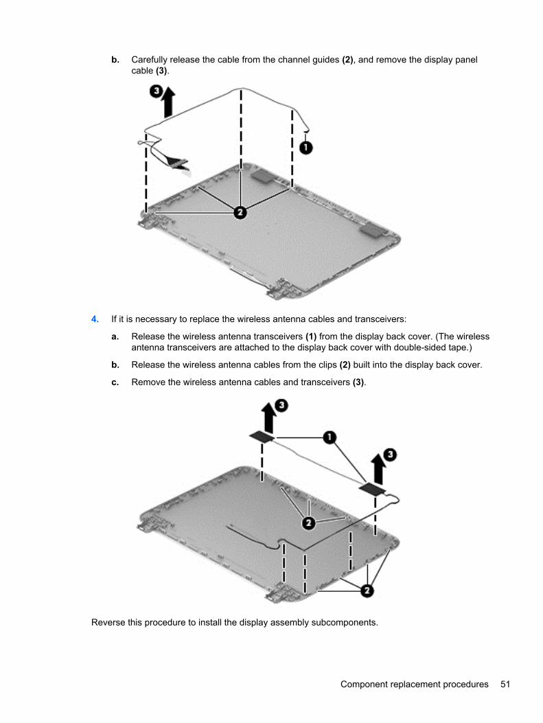
b. Carefully release the cable from the channel guides (2), and remove the display panelcable (3).
4. If it is necessary to replace the wireless antenna cables and transceivers:
a. Release the wireless antenna transceivers (1) from the display back cover. (The wirelessantenna transceivers are attached to the display back cover with double-sided tape.)
b. Release the wireless antenna cables from the clips (2) built into the display back cover.
c. Remove the wireless antenna cables and transceivers (3).
Reverse this procedure to install the display assembly subcomponents.
Component replacement procedures 51

Power connector cable
Description Spare part number
Power connector cable (includes bracket) 730900-001
Before removing the power connector cable, follow these steps:
1. Turn off the computer. If you are unsure whether the computer is off or in Hibernation, turn thecomputer on, and then shut it down through the operating system.
2. Disconnect the power from the computer by unplugging the power cord from the computer.
3. Disconnect all external devices from the computer.
4. Remove the battery (see Battery on page 33).
5. Remove the service door (see Service door on page 34).
Remove the power connector cable:
1. Remove the two Phillips PM2.0×5.5 screws (1) and the Phillips PM2.5×10.5 screw (2) thatsecure the display assembly right hinge to the computer.
2. Open the display assembly right hinge (3) as far as it will open.
3. Disconnect the power connector cable (4) from the system board.
4. Release the power connector cable from the retention clips (5) and routing channel built into thebottom cover.
52 Chapter 6 Removal and replacement procedures for Authorized Service Provider parts
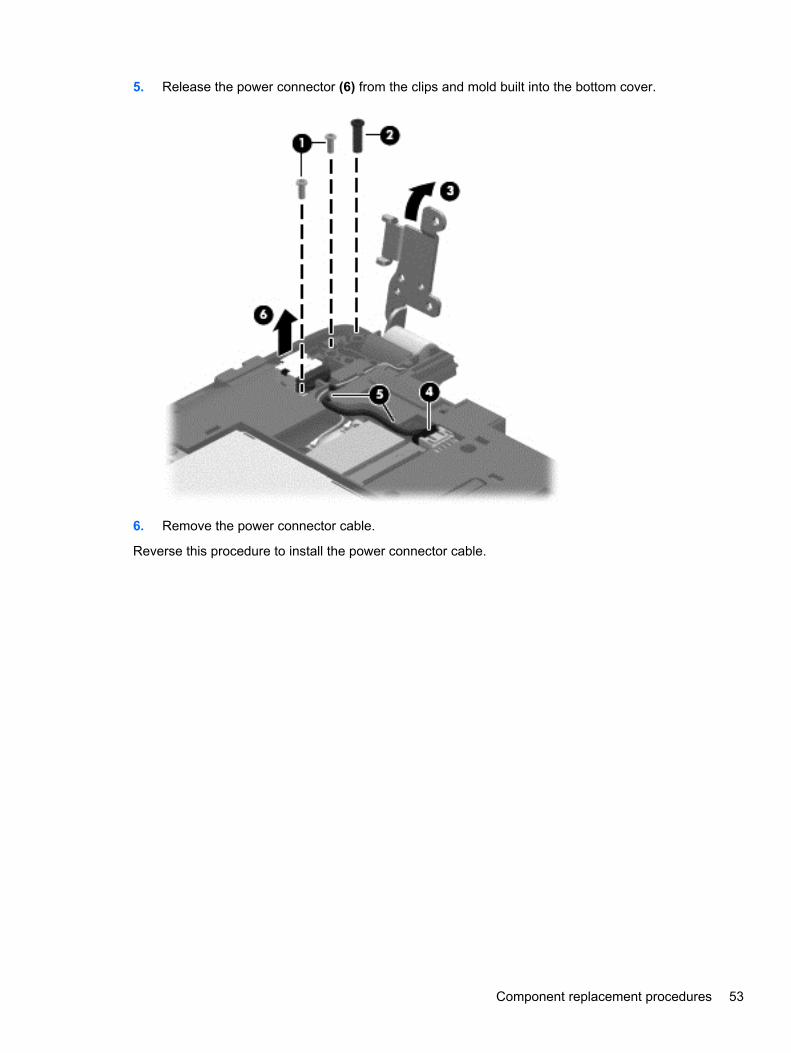
5. Release the power connector (6) from the clips and mold built into the bottom cover.
6. Remove the power connector cable.
Reverse this procedure to install the power connector cable.
Component replacement procedures 53

Bottom cover
Description Spare part number
TouchSmart models (includes left and right corner covers) 730887-001
HP 215 G1 Notebook PC non-touchscreen models (includes left and right corner covers) 747750-001
Before removing the bottom cover, follow these steps:
1. Turn off the computer. If you are unsure whether the computer is off or in Hibernation, turn thecomputer on, and then shut it down through the operating system.
2. Disconnect the power from the computer by unplugging the power cord from the computer.
3. Disconnect all external devices from the computer.
4. Remove the battery (see Battery on page 33).
5. Remove the service door (see Service door on page 34).
6. Disconnect the RTC battery cable from the system board (see RTC battery on page 40).
7. Remove the display assembly (see Display assembly on page 46).
NOTE: When replacing the bottom cover, be sure that the RTC battery is removed from thedefective bottom cover and installed in the replacement bottomcover.
Remove the bottom cover:
1. Release the zero insertion force (ZIF) connector (1) to which the keyboard cable is attached, andthen disconnect the keyboard cable from the system board.
2. Release the ZIF connector (2) to which the TouchPad button board cable is attached, and thendisconnect the TouchPad button board cable from the system board.
54 Chapter 6 Removal and replacement procedures for Authorized Service Provider parts

3. Release the ZIF connector (3) to which the power button board ribbon cable is attached, andthen disconnect the power button board ribbon cable from the system board.
4. Remove the thirteen Phillips PM2.0×4.5 screws that secure the bottom cover to the top cover.
Component replacement procedures 55

5. Remove the bottom cover from the top cover.
Reverse this procedure to install the bottom cover.
Power button board
Description Spare part number
Power button board (includes cable) 730899-001
Before removing the power button board, follow these steps:
1. Turn off the computer. If you are unsure whether the computer is off or in Hibernation, turn thecomputer on, and then shut it down through the operating system.
2. Disconnect the power from the computer by unplugging the power cord from the computer.
3. Disconnect all external devices from the computer.
4. Remove the battery (see Battery on page 33), and then remove the following components:
a. Service door (see Service door on page 34)
b. Display assembly (see Display assembly on page 46)
c. Bottom cover (see Bottom cover on page 54)
Remove the power button board:
1. Remove the two Phillips PM2.0×2.75 screws (1) that secure the power button board to thetop cover.
2. Detach the power button board cable (2) from the top cover. (The power button board cable isattached to the top cover with double-sided tape.)
56 Chapter 6 Removal and replacement procedures for Authorized Service Provider parts

3. Remove the power button board (3) and cable.
Reverse this procedure to install the power button board.
Component replacement procedures 57

TouchPad button board
Description Spare part number
TouchPad button board (includes TouchPad cable, TouchPad button board cable, andTouchPad button board bracket)
730898-001
Before removing the TouchPad button board, follow these steps:
1. Turn off the computer. If you are unsure whether the computer is off or in Hibernation, turn thecomputer on, and then shut it down through the operating system.
2. Disconnect the power from the computer by unplugging the power cord from the computer.
3. Disconnect all external devices from the computer.
4. Remove the battery (see Battery on page 33), and then remove the following components:
a. Service door (see Service door on page 34)
b. Display assembly (see Display assembly on page 46)
c. Bottom cover (see Bottom cover on page 54)
Remove the TouchPad button board:
1. Release the ZIF connector (1) to which the TouchPad board cable is attached, and thendisconnect the TouchPad board cable from the TouchPad board.
2. Remove the two Phillips PM2.0×4.5 screws (2) that secure the TouchPad button board to thetop cover.
3. Remove the TouchPad button board bracket (3).
58 Chapter 6 Removal and replacement procedures for Authorized Service Provider parts

4. Remove the TouchPad button board (4) and cables.
Reverse this procedure to install the TouchPad button board.
Component replacement procedures 59

Media card reader board
Description Spare part number
Media card reader board (includes cable) 730897-001
Before removing the media card reader board, follow these steps:
1. Turn off the computer. If you are unsure whether the computer is off or in Hibernation, turn thecomputer on, and then shut it down through the operating system.
2. Disconnect the power from the computer by unplugging the power cord from the computer.
3. Disconnect all external devices from the computer.
4. Remove the battery (see Battery on page 33), and then remove the following components:
a. Service door (see Service door on page 34)
b. Display assembly (see Display assembly on page 46)
c. Bottom cover (see Bottom cover on page 54)
Remove the media card reader board:
1. Release the ZIF connector (1) to which the media card reader board cable is attached, and thendisconnect the media card reader board cable from the system board.
2. Remove the Phillips PM2.0×4.5 screw (2) that secures the media card reader board to thetop cover.
3. Remove the media card reader board (3) and cable.
Reverse this procedure to install the media card reader board.
60 Chapter 6 Removal and replacement procedures for Authorized Service Provider parts

Fan
Description Spare part number
Fan (includes cable and cowling) 730903-001
Before removing the fan, follow these steps:
1. Turn off the computer. If you are unsure whether the computer is off or in Hibernation, turn thecomputer on, and then shut it down through the operating system.
2. Disconnect the power from the computer by unplugging the power cord from the computer.
3. Disconnect all external devices from the computer.
4. Remove the battery (see Battery on page 33), and then remove the following components:
a. Service door (see Service door on page 34)
b. Display assembly (see Display assembly on page 46)
c. Bottom cover (see Bottom cover on page 54)
Remove the fan:
1. Disconnect the fan cable (1) from the system board.
2. Detach the cowling tape (2) that secures the fan to the heat sink.
3. Remove the two Phillips PM2.0×4.5 screws (3) that secure the fan to the system board.
4. Remove the fan (4).
Reverse this procedure to install the fan.
Component replacement procedures 61

Monitor connector board
Description Spare part number
Monitor connector board (includes cable) 730901-001
Before removing the monitor connector board, follow these steps:
1. Turn off the computer. If you are unsure whether the computer is off or in Hibernation, turn thecomputer on, and then shut it down through the operating system.
2. Disconnect the power from the computer by unplugging the power cord from the computer.
3. Disconnect all external devices from the computer.
4. Remove the battery (see Battery on page 33), and then remove the following components:
a. Service door (see Service door on page 34)
b. Display assembly (see Display assembly on page 46)
c. Bottom cover (see Bottom cover on page 54)
Remove the monitor connector board:
1. Disconnect the monitor connector board cable (1) from the system board.
2. Remove the Phillips PM2.0×2.25 broad head screw (2) that secures the monitor connectorboard to the top cover.
3. Remove the monitor connector board (3) and cable.
Reverse this procedure to install the monitor connector board.
62 Chapter 6 Removal and replacement procedures for Authorized Service Provider parts

System board
NOTE: The system board spare part kit includes replacement thermal material.
Description Spare part number
HP Pavilion TouchSmart 11 Notebook PC/ HP Pavilion 11 Notebook PC
Equipped with an AMD A4-1250 processor, a graphics subsystem with UMA memory, for use oncomputers with Windows 8.1 Standard operating system
744789-501
Equipped with an AMD A6-1450 processor, a graphics subsystem with UMA memory, for use oncomputers with the Windows 8.1 Standard operating system
744790-501
HP 215 G1 Notebook PC
Equipped with an AMD A4-1250 processor, a graphics subsystem with UMA memory, for use oncomputers with Windows 7 operating system
744185-001
Equipped with an AMD A4-1250 processor, a graphics subsystem with UMA memory, for use oncomputers with Windows 8.1 Standard operating system
744185-501
Equipped with an AMD A4-1250 processor, a graphics subsystem with UMA memory, for use oncomputers with Windows 8.1 Professional operating system
744185-601
Equipped with an AMD A6-1450 processor, a graphics subsystem with UMA memory, for use oncomputers with Windows 7 operating system
744189-001
Equipped with an AMD A6-1450 processor, a graphics subsystem with UMA memory, for use oncomputers with Windows 8.1 Standard operating system
744189-501
Equipped with an AMD A6-1450 processor, a graphics subsystem with UMA memory, for use oncomputers with Windows 8.1 Professional operating system
744189-601
Before removing the system board, follow these steps:
1. Turn off the computer. If you are unsure whether the computer is off or in Hibernation, turn thecomputer on, and then shut it down through the operating system.
2. Disconnect the power from the computer by unplugging the power cord from the computer.
3. Disconnect all external devices from the computer.
4. Remove the battery (see Battery on page 33), and then remove the following components:
a. Service door (see Service door on page 34)
b. Hard drive (see Hard drive on page 35)
c. Display assembly (see Display assembly on page 46)
d. Bottom cover (see Bottom cover on page 54)
e. Media card reader board (see Media card reader board on page 60)
f. Fan (see Fan on page 61)
Component replacement procedures 63

NOTE: When replacing the system board, be sure that the following components are removed fromthe defective system board and installed on the replacement system board:
● WLAN module (see WLAN module on page 37)
● Memory module (see Memory module on page 39)
● Heat sink (see Heat sink on page 65)
Remove the system board:
1. Disconnect the monitor connector board cable (1) from the system board.
2. Disconnect the speaker cable (2) from the system board.
3. Release the speaker cable from the tabs (3) built into the system board.
4. Remove the three Phillips PM2.0×4.5 screws (1) that secure the system board to the top cover.
5. Lift the left side of the system board (2) until it rests at an angle.
64 Chapter 6 Removal and replacement procedures for Authorized Service Provider parts

6. Remove the system board (3) by sliding it up and to the left an angle.
Reverse this procedure to install the system board.
Heat sink
Description Spare part number
Heat sink (includes 4 captive screws and replacement thermal material) 730902-001
Before removing the heat sink, follow these steps:
1. Turn off the computer. If you are unsure whether the computer is off or in Hibernation, turn thecomputer on, and then shut it down through the operating system.
2. Disconnect the power from the computer by unplugging the power cord from the computer.
3. Disconnect all external devices from the computer.
4. Remove the battery (see Battery on page 33), and then remove the following components:
a. Service door (see Service door on page 34)
b. Hard drive (see Hard drive on page 35)
c. Display assembly (see Display assembly on page 46)
d. Bottom cover (see Bottom cover on page 54)
e. Media card reader board (see Media card reader board on page 60)
Component replacement procedures 65

f. Fan (see Fan on page 61)
g. System board (see System board on page 63)
Remove the heat sink:
1. Turn the system board upside down, with the front toward you.
2. Following the 1 through 4 sequence stamped into the heat sink, loosen the four captive PhillipsPM2.0×2.5 screws (1) that secure the heat sink to the system board.
3. Remove the heat sink (2).
NOTE: Due to the adhesive quality of the thermal material located between the heat sink andthe system board components, it may be necessary to move the heat sink from side to side todetach it.
NOTE: The thermal material must be thoroughly cleaned from the surfaces of the heat sink andthe system board components each time the heat sink is removed. Thermal paste is used on theprocessor (1) and the heat sink section (2) that services it
66 Chapter 6 Removal and replacement procedures for Authorized Service Provider parts

Reverse this procedure to install the heat sink.
Speakers
Description Spare part number
Speaker Kit (includes left and right speakers and cables) 730890-001
Before removing the speakers, follow these steps:
1. Turn off the computer. If you are unsure whether the computer is off or in Hibernation, turn thecomputer on, and then shut it down through the operating system.
2. Disconnect the power from the computer by unplugging the power cord from the computer.
3. Disconnect all external devices from the computer.
4. Remove the battery (see Battery on page 33), and then remove the following components:
a. Service door (see Service door on page 34)
b. Hard drive (see Hard drive on page 35)
c. Display assembly (see Display assembly on page 46)
d. Bottom cover (see Bottom cover on page 54)
e. Media card reader board (see Media card reader board on page 60)
f. Fan (see Fan on page 61)
g. System board (see System board on page 63)
Component replacement procedures 67

Remove the speakers:
1. Remove the two Phillips PM2.0×3.75 screws (1) and the two Phillips PM2.0×2.75 screws (2) thatsecure the speakers to the bottom cover.
2. Remove the speakers (3).
Reverse this procedure to install the speakers.
68 Chapter 6 Removal and replacement procedures for Authorized Service Provider parts

7 Using Setup Utility (BIOS) and HP PCHardware Diagnostics (UEFI)
Setup Utility, or Basic Input/Output System (BIOS), controls communication between all the input andoutput devices on the system (such as disk drives, display, keyboard, mouse, and printer). SetupUtility (BIOS) includes settings for the types of devices installed, the startup sequence of thecomputer, and the amount of system and extended memory.
Starting Setup Utility (BIOS)To start Setup Utility (BIOS), turn on or restart the computer, quickly press esc, and then press f10.
Information about how to navigate in Setup Utility (BIOS) is located at the bottom of the screen.
NOTE: Use extreme care when making changes in Setup Utility (BIOS). Errors can prevent thecomputer from operating properly.
Updating the BIOSUpdated versions of the BIOS may be available on the HP website.
Most BIOS updates on the HP website are packaged in compressed files called SoftPaqs.
Some download packages contain a file named Readme.txt, which contains information regardinginstalling and troubleshooting the file.
Determining the BIOS version
To determine whether available BIOS updates contain later BIOS versions than those currentlyinstalled on the computer, you need to know the version of the system BIOS currently installed.
BIOS version information (also known as ROM date and System BIOS) can be revealed by pressingfn+esc (if you are already in Windows) or by using Setup Utility (BIOS).
1. Start Setup Utility (BIOS) (see Starting Setup Utility (BIOS) on page 69).
2. Use the arrow keys to select Main.
3. To exit Setup Utility (BIOS) without saving your changes, use the arrow keys to select Exit,select Exit Discarding Changes, and then press enter.
4. Select Yes.
Starting Setup Utility (BIOS) 69

Downloading a BIOS update
CAUTION: To reduce the risk of damage to the computer or an unsuccessful installation, downloadand install a BIOS update only when the computer is connected to reliable external power using theAC adapter. Do not download or install a BIOS update while the computer is running on batterypower, docked in an optional docking device, or connected to an optional power source. During thedownload and installation, follow these instructions:
Do not disconnect power from the computer by unplugging the power cord from the AC outlet.
Do not shut down the computer or initiate Sleep.
Do not insert, remove, connect, or disconnect any device, cable, or cord.
Downloading a Windows 8.1 BIOS update
1. From the Start screen, type support, and then select the HP Support Assistant app.
2. Click Updates and tune-ups, and then click Check for HP updates now.
3. Follow the on-screen instructions.
4. At the download area, follow these steps:
a. Identify the most recent BIOS update and compare it to the BIOS version currently installedon your computer. If the update is more recent than your BIOS, make a note of the date,name, or other identifier. You may need this information to locate the update later, after ithas been downloaded to your hard drive.
b. Follow the on-screen instructions to download your selection to the hard drive.
If the update is more recent than your BIOS, make a note of the path to the location on yourhard drive where the BIOS update is downloaded. You will need to access this path whenyou are ready to install the update.
NOTE: If you connect your computer to a network, consult the network administrator beforeinstalling any software updates, especially system BIOS updates.
NOTE: After a message on the screen reports a successful installation, you can delete thedownloaded file from your hard drive.
BIOS installation procedures vary. Follow any instructions that are revealed on the screen after thedownload is complete. If no instructions are revealed, follow these steps:
1. From the Start screen, type e, and then select File Explorer.
2. Click your hard drive designation. The hard drive designation is typically Local Disk (C:).
3. Using the hard drive path you recorded earlier, open the folder on your hard drive that containsthe update.
4. Double-click the file that has an .exe extension (for example, filename.exe).
The BIOS installation begins.
5. Complete the installation by following the on-screen instructions.
70 Chapter 7 Using Setup Utility (BIOS) and HP PC Hardware Diagnostics (UEFI)

Downloading a Windows 7 BIOS update
1. Select Start > Help and Support > Maintain.
2. Follow the on-screen instructions to identify your computer and access the BIOS update youwant to download.
3. At the download area, follow these steps:
a. Identify the most recent BIOS update and compare it to the BIOS version currently installedon your computer. If the update is more recent than your BIOS, make a note of the date,name, or other identifier. You may need this information to locate the update later, after ithas been downloaded to your hard drive.
b. Follow the on-screen instructions to download your selection to the hard drive.
If the update is more recent than your BIOS, make a note of the path to the location on yourhard drive where the BIOS update is downloaded. You will need to access this path whenyou are ready to install the update.
NOTE: If you connect your computer to a network, consult the network administrator beforeinstalling any software updates, especially system BIOS updates.
BIOS installation procedures vary. Follow any instructions that are displayed on the screen after thedownload is complete. If no instructions are displayed, follow these steps:
1. Open Windows Explorer by selecting Start > Computer.
2. Double-click your hard drive designation. The hard drive designation is typically Local Disk (C:).
3. Using the hard drive path you recorded earlier, open the folder on your hard drive that containsthe update.
4. Double-click the file that has an .exe extension (for example, filename.exe).
The BIOS installation begins.
5. Complete the installation by following the on-screen instructions.
NOTE: After a message on the screen reports a successful installation, you can delete thedownloaded file from your hard drive.
Using HP PC Hardware Diagnostics (UEFI) (select modelsonly)
HP PC Hardware Diagnostics is a Unified Extensible Firmware Interface (UEFI) that allows you to rundiagnostic tests to determine whether the computer hardware is functioning properly. The tool runsoutside the operating system so that it can isolate hardware failures from issues that are caused bythe operating system or other software components.
Using HP PC Hardware Diagnostics (UEFI) (select models only) 71

To start HP PC Hardware Diagnostics UEFI:
1. Turn on or restart the computer, quickly press esc, and then press f2.
The BIOS searches three places for the HP PC Hardware Diagnostics (UEFI) tools in thefollowing order:
a. Connected USB drive
NOTE: To download the HP PC Hardware Diagnostics (UEFI) tool to a USB drive, seeDownloading HP PC Hardware Diagnostics (UEFI) to a USB device on page 72.
b. Hard drive
c. BIOS
2. Click the type of diagnostic test you want to run, and then follow the on-screen instructions.
NOTE: If you need to stop a diagnostic test, press esc.
Downloading HP PC Hardware Diagnostics (UEFI) to a USB device
NOTE: The HP PC Hardware Diagnostics (UEFI) download instructions are provided in Englishonly.
1. Go to http://www.hp.com.
2. Click Support & Drivers, and then click the Drivers & Software tab.
3. Enter the product name in the text box, and then click Search.
4. Select your computer model, and then select your operating system.
5. In the Diagnostic section, click HP UEFI Support Environment.
– or –
Click Download, and then select Run.
72 Chapter 7 Using Setup Utility (BIOS) and HP PC Hardware Diagnostics (UEFI)

8 Specifications
Computer specifications
Metric U.S.
Dimensions
Width 29.0 cm 11.4 in
Depth 21.7 cm 8.5 in
Height 2.2 cm 0.9 in
Weight 1.5 kg 3.7 lbs
Input power
Operating voltage and current 19.5 V dc @ 2.31 A – 45 W
19.5 V dc @ 3.33 A – 65 W
Temperature
Operating 5°C to 35°C 41°F to 95°F
Nonoperating -20°C to 60°C -4°F to 140°F
Relative humidity (noncondensing)
Operating 10% to 90%
Nonoperating 5% to 95%
Maximum altitude (unpressurized)
Operating -15 m to 3,048 m -50 ft to 10,000 ft
Nonoperating -15 m to 12,192 m -50 ft to 40,000 ft
NOTE: Applicable product safety standards specify thermal limits for plastic surfaces. The device operates well within thisrange of temperatures.
Hard drive specifications
500 GB, 5400 rpm* 320 GB, 5400 rpm*
Dimensions
Height 7.0 mm 7.0 mm
Length 100.4 mm 100.4 mm
Width 69.9 mm 69.9 mm
Weight 110 g 110 g
Interface type SATA SATA
Computer specifications 73

500 GB, 5400 rpm* 320 GB, 5400 rpm*
Transfer rate (synchronous, maximum) 1.1 GB/sec 1.1 GB/sec
Security ATA security ATA security
Seek times (typical read, including setting)
Single track 1.5 ms 1.5 ms
Average (read/write) 11/13 ms 11/13 ms
Maximum 22 ms 22 ms
Logical blocks 976,773,168 628,142,448
Disk rotational speed 5400 rpm 5400 rpm
Operating temperature 0°C to 60°C (32°F to 140°F) 0°C to 60°C (32°F to 140°F)
*1 GB = 1 billion bytes when referring to hard drive storage capacity. Actual accessible capacity is less.
NOTE: Certain restrictions and exclusions apply. Contact technical support for details.
74 Chapter 8 Specifications

9 Windows 7 – Backing up, restoring,and recovering
Your computer includes tools provided by the operating system and HP to help you safeguard yourinformation and retrieve it if ever needed.
Creating backups1. Use HP Recovery Manager to create recovery media immediately after you set up the working
computer.
2. As you add hardware and software programs, create system restore points.
3. As you add photos, video, music, and other personal files, create a backup of your system andpersonal information.
Creating recovery media to recover the original system
After you successfully set up the computer, you should create recovery discs or a recovery flash driveusing HP Recovery Manager. You will need these recovery discs or recovery flash drive to perform asystem recovery should the hard drive become corrupted. A system recovery reinstalls the originaloperating system, and then configures the settings for the default programs.
What you need to know
● Only one set of recovery media can be created. Handle these recovery tools carefully, and keepthem in a safe place.
● HP Recovery Manager examines the computer and determines the required storage capacity forthe flash drive or the number of blank DVD discs that will be required.
Use DVD-R, DVD+R, DVD-R DL, DVD+R DL discs or a flash drive. Do not use rewriteable discssuch as CD±RW, DVD±RW, double-layer DVD±RW, and BD-RE (rewritable Blu-ray) discs; theyare not compatible with HP Recovery Manager software.
● You can use an optional external optical drive (purchased separately) to create recovery discs,or you can obtain recovery discs for your computer from support through the HP website. Go tohttp://www.hp.com/support, select your country or region, and follow the on-screen instructions.If you use an external optical drive, it must be connected directly to a USB port on the computer,not to a USB port on an external device, such as a USB hub.
● Be sure that the computer is connected to AC power before you begin creating the recoverymedia.
● The creation process can take up to an hour or more. Do not interrupt the creation process.
● Store the recovery media in a safe location, separate from the computer.
● If necessary, you can exit the program before you have finished creating the recovery media.The next time you open HP Recovery Manager, you will be prompted to continue the process.
Creating backups 75

Creating the recovery media
1. Select Start and type recovery in the search field. Select Recovery Manager from the list.Allow the action to continue, if prompted.
2. Click Recovery Media Creation.
3. Follow the on-screen instructions to continue.
To recover, see Recovering the original system using HP Recovery Manager on page 78.
Creating system restore points
A system restore point is a snapshot of certain hard drive contents saved by Windows SystemRestore at a specific time. A restore point contains information such as registry settings that Windowsuses. Restoring to a previous restore point allows you to reverse changes that have been made to thesystem since the restore point was created.
Restoring to an earlier system restore point does not affect data files saved or emails created sincethe last restore point, but it does affect software you may have installed.
For example, if you download a photo from a digital camera and then restore the computer to thestate it was on the previous day, the photo remains on the computer.
However, if you install photo viewing software and then restore your computer to the state it was onthe previous day, the software will be uninstalled, and you won't be able to use it.
What you need to know
● If you restore to a restore point and then change your mind, you can undo the restoration.
● You should create system restore points:
◦ Before you add or change software or hardware
◦ Periodically, whenever the computer is running normally
● System Restore also saves shadow copies of files that have been changed since the last restorepoint was created. For more information about using shadow copies to restore, see Help andSupport.
Creating a system restore point
1. Select Start > Control Panel > System and Security > System.
2. In the left pane, click System Protection.
3. Click the System Protection tab.
4. Click Create, and follow the on-screen instructions.
To restore, see Restoring to a previous system restore point on page 78.
Backing up system and personal information
Your computer stores information that is important to you, such as files, emails, and photos, and youwill want to keep that information even if you download a virus or the system stops working properly.How completely you are able to recover your files depends on how recent your backup is. As you addnew software and data files, you should create backups on a regular basis.
76 Chapter 9 Windows 7 – Backing up, restoring, and recovering

Tips for a successful backup
● Number backup discs before inserting them into the optical drive.
● Store personal files in the Documents, Music, Pictures, and Videos libraries, and back up thesefolders periodically.
● Save customized settings in a window, toolbar, or menu bar by taking a screen shot of yoursettings. The screen shot can be a time-saver if you have to re-enter your preferences.
To create a screen shot:
1. Display the screen you want to save.
2. Copy the screen image:
To copy only the active window, press alt+prt sc.
To copy the entire screen, press prt sc.
3. Open a word-processing document or graphics editing program, and then select Edit > Paste.The screen image is added to the document.
4. Save and print the document.
What you need to know
● You can back up your information to an optional external hard drive, a flash drive, a networkdrive, or discs.
● Connect the computer to AC power during backups.
● Allow enough time for the backup. Depending on files sizes, it may take more than an hour.
● Verify the amount of free space on your backup storage device before you back up.
● You should back up:
◦ Before adding or changing software or hardware.
◦ Before the computer is repaired or restored.
◦ On a regular schedule to be sure you have recent copies of personal information.
◦ After you add many files—for example, if you saved videos from a birthday party.
◦ Before using antivirus software to remove a malicious program.
◦ After adding information that is hard to replace, such as pictures, videos, music, projectfiles, or data records.
Creating a backup using Windows Backup and Restore
Windows allows you to back up files using Windows Backup and Restore. You can select the levelyou want to back up, from individual folders to drives. The backups are compressed to save space.To back up:
1. Select Start > Control Panel > System and Security > Backup and Restore.
2. Follow the on-screen instructions to schedule and create a backup.
NOTE: Windows includes the User Account Control feature to improve the security of the computer.You may be prompted for your permission or password for tasks such as installing software, runningutilities, or changing Windows settings. See Help and Support for more information.
Creating backups 77

To restore, see Restoring specific files using Windows Backup and Restore on page 78.
Restore and recovery
Restoring to a previous system restore point
Sometimes installing a software program causes your computer or Windows to behave unpredictably.Usually uninstalling the software fixes the problems. If uninstalling does not fix the problems, you canrestore the computer to a previous system restore point (created at an earlier date and time).
To restore to a previous system restore point, when the computer was running correctly:
1. Select Start > Control Panel > System and Security > System.
2. In the left pane, click System Protection.
3. Click the System Protection tab.
4. Click System Restore, and follow the on-screen instructions.
Restoring specific files
If files are accidentally deleted from the hard disk and they can no longer be restored from theRecycle Bin, or if files become corrupt, restoring specific files is useful. Restoring specific files is alsouseful if you ever choose to recover the original system using HP Recovery Manager. You can onlyrestore specific files that you have backed up before.
Restoring specific files using Windows Backup and Restore
Windows allows you to restore files that were backed up using Windows Backup and Restore:
1. Select Start > Control Panel > System and Security > Backup and Restore.
2. Follow the on-screen instructions to restore your backup.
NOTE: Windows includes the User Account Control feature to improve the security of the computer.You may be prompted for your permission or password for tasks such as installing software, runningutilities, or changing Windows settings. See Help and Support for more information.
Recovering the original system using HP Recovery Manager
HP Recovery Manager software allows you to repair or recover the computer to its original factorystate.
What you need to know
● HP Recovery Manager recovers only software that was installed at the factory. For software notprovided with this computer, you must either download the software from the manufacturer'swebsite or reinstall the software from the disc provided by the manufacturer.
● A system recovery should be used as a final attempt to correct computer issues. If you have notalready tried restore points (see Restoring to a previous system restore point on page 78) andpartial restores (see Restoring specific files on page 78), try them before using HP RecoveryManager to recover your system.
● A system recovery must be performed if the computer hard drive fails or if all attempts to correctany functional computer issues fail.
78 Chapter 9 Windows 7 – Backing up, restoring, and recovering

● If the recovery media do not work, you can obtain recovery discs for your system from supportthrough the HP website. Go to http://www.hp.com/support, select your country or region, andfollow the on-screen instructions.
● The Minimized Image Recovery option is recommended for advanced users only. All hardware-related drivers and software are re-installed, but other software applications are not. Do notinterrupt the process until it is complete, otherwise the recovery will fail.
Recovering using HP Recovery partition (select models only)
The HP Recovery partition (select models only), allows you to restore your system without the needfor recovery discs or a recovery flash drive. This type of recovery can only be used if the hard drive isstill working.
To check for the presence of a recovery partition, select Start, right-click Computer then selectManage > Disk Management. If the recovery partition is present, a Recovery drive is listed in thewindow.
NOTE: Recovery discs have been included if your computer did not ship with a recovery partition.
1. Access HP Recovery Manager in either of the following ways:
● Select Start and type recovery in the search field. Select Recovery Manager from thelist.
– or –
● Turn on or restart the computer, and then press esc while the “Press the ESC key forStartup Menu” message is displayed at the bottom of the screen. Then press f11 while the“F11 (System Recovery)” message is displayed on the screen.
2. Click System Recovery in the HP Recovery Manager window.
3. Follow the on-screen instructions.
Recovering using the recovery media
1. If possible, back up all personal files.
2. Insert the first recovery disc into the optical drive on your computer or an optional externaloptical drive, and then restart the computer.
– or –
Insert the recovery flash drive into a USB port on your computer, and then restart the computer.
NOTE: If the computer does not automatically restart in HP Recovery Manager, change thecomputer boot order. See Changing the computer boot order on page 80.
3. Press f9 at system bootup.
4. Select the optical drive or the flash drive.
5. Follow the on-screen instructions.
Restore and recovery 79

Changing the computer boot order
To change the boot order for recovery discs:
1. Restart the computer.
2. Press esc while the computer is restarting, and then press f9 for boot options.
3. Select Internal CD/DVD ROM Drive from the boot options window.
To change the boot order for a recovery flash drive:
1. Insert the flash drive into a USB port.
2. Restart the computer.
3. Press esc while the computer is restarting, and then press f9 for boot options.
4. Select the flash drive from the boot options window.
80 Chapter 9 Windows 7 – Backing up, restoring, and recovering

10 Windows 8.1 – Backing up, restoring,and recovering
Your computer includes tools provided by HP and Windows to help you safeguard your informationand retrieve it if you ever need to. These tools will help you return your computer to a proper workingstate or even back to the original factory state, all with simple steps.
This chapter provides information about the following processes:
● Creating recovery media and backups
● Restoring and recovering your system
NOTE: This chapter describes an overview of backing up, restoring and recovering options. Formore details about the tools provided, see Help and Support. From the Start screen, type help, andthen select Help and Support.
Creating recovery media and backups1. After you successfully set up the computer, create HP Recovery media. This step creates a
backup of the HP Recovery partition on the computer. The backup can be used to reinstall theoriginal operating system in cases where the hard drive is corrupted or has been replaced.
HP Recovery media you create will provide the following recovery options:
● System Recovery—Reinstalls the original operating system and the programs that wereinstalled at the factory.
● Minimized Image Recovery—Reinstalls the operating system and all hardware-relateddrivers and software, but not other software applications.
● Factory Reset—Restores the computer to the state its original factory state by deleting allinformation from the hard drive and re-creating the partitions. Then it reinstalls theoperating system and the software that was installed at the factory.
See Creating recovery media and backups on page 81.
2. Use the Windows tools to create system restore points and create backups of personalinformation. For more information and steps, see Windows Help and Support. From the Startscreen, type help, and then select Help and Support.
Creating HP Recovery media
HP Recovery Manager is a software program that offers a way to create recovery media after yousuccessfully set up the computer. HP Recovery media can be used to perform system recovery if thehard drive becomes corrupted. System recovery reinstalls the original operating system and thesoftware programs installed at the factory, and then configures the settings for the programs. HP
Creating recovery media and backups 81

Recovery media can also be used to customize the system or restore the factory image if you replacethe hard drive.
● Only one set of HP Recovery media can be created. Handle these recovery tools carefully, andkeep them in a safe place.
● HP Recovery Manager examines the computer and determines the required storage capacity forthe blank USB flash drive or the number of blank DVD discs that will be required.
● To create recovery discs, your computer must have an optical drive with DVD writer capability,and you must use only high-quality blank DVD-R, DVD+R, DVD-R DL, DVD+R DL discs. Do notuse rewritable discs such as CD±RW, DVD±RW, double-layer DVD±RW, or BD-RE (rewritableBlu-ray) discs; they are not compatible with HP Recovery Manager software. Or instead you canuse a high-quality blank USB flash drive.
● If your computer does not include an integrated optical drive with DVD writer capability, but youwould like to create DVD recovery media, you can use an external optical drive (purchasedseparately) to create recovery discs, or you can obtain recovery discs for your computer fromsupport. See the Worldwide Telephone Numbers booklet included with the computer. You canalso find contact information for the HP website. For U.S. support, go to http://www.hp.com/go/contactHP. For worldwide support, go to http://welcome.hp.com/country/us/en/wwcontact_us.html. If you use an external optical drive, it must be connected directly to a USBport on the computer; the drive cannot be connected to a USB port on an external device, suchas a USB hub.
● Be sure that the computer is connected to AC power before you begin creating the recoverymedia.
● The creation process can take up to an hour or more. Do not interrupt the creation process.
● If necessary, you can exit the program before you have finished creating all of the recoveryDVDs. HP Recovery Manager will finish burning the current DVD. The next time you start HPRecovery Manager, you will be prompted to continue, and the remaining discs will be burned.
To create HP Recovery media:
1. From the Start screen, type recovery, and then select HP Recovery Manager.
2. Select Recovery Media Creation, and follow the on-screen instructions to continue.
If you ever need to recover the system, see Recovering using HP Recovery Manager on page 83.
Restore and recoveryThere are several options for recovering your system. Choose the method that best matches yoursituation and level of expertise:
● Windows offers several options for restoring from backup, refreshing the computer, and resettingthe computer to its original state. For more information and steps, see Help and Support. Fromthe Start screen, type help, and then select Help and Support.
● If you need to correct a problem with a preinstalled application or driver, use the Drivers andApplications Reinstall option of HP Recovery Manager to reinstall the individual application ordriver.
From the Start screen, type recovery, select HP Recovery Manager, and then select Driversand Applications Reinstall, and follow the on-screen instructions.
● If you want to reset your computer using a minimized image, you can choose the HP MinimizedImage Recovery option from the HP Recovery partition or HP Recovery media. Minimized Image
82 Chapter 10 Windows 8.1 – Backing up, restoring, and recovering

Recovery installs only drivers and hardware-enabling applications. Other applications included inthe image continue to be available for installation through the Drivers and Applications Reinstalloption in HP Recovery Manager.
For more information, see Recovering using HP Recovery Manager on page 83.
● If you want to recover the computer's original factory partitioning and content, you can choosethe System Recovery option from the HP Recovery media. For more information, seeRecovering using HP Recovery Manager on page 83.
● If you have replaced the hard drive, you can use the Factory Reset option of HP Recoverymedia to restore the factory image to the replacement drive. For more information, seeRecovering using HP Recovery Manager on page 83.
● If you wish to remove the recovery partition to reclaim hard drive space, HP Recovery Manageroffers the Remove Recovery Partition option.
For more information, see Using the HP Recovery partition on page 83.
Recovering using HP Recovery Manager
HP Recovery Manager software allows you to recover the computer to its original factory state. Usingthe HP Recovery media you created, you can choose from one of the following recovery options:
● System Recovery—Reinstalls the original operating system, and then configures the settings forthe programs that were installed at the factory.
● Minimized Image Recovery—Reinstalls the operating system and all hardware-related driversand software, but not other software applications.
● Factory Reset—Restores the computer to the state its original factory state by deleting allinformation from the hard drive and re-creating the partitions. Then it reinstalls the operatingsystem and the software that was installed at the factory.
The HP Recovery partition allows System Recovery and Minimized Image Recovery.
What you need to know
● HP Recovery Manager recovers only software that was installed at the factory. For software notprovided with this computer, you must either download the software from the manufacturer'swebsite or reinstall the software from the media provided by the manufacturer.
● Recovery through HP Recovery Manager should be used as a final attempt to correct computerissues.
● HP Recovery media must be used if the computer hard drive fails.
● To use the Factory Reset or System Recovery options, you must use HP Recovery media.
● If the HP Recovery media do not work, you can obtain recovery media for your system from theHP website. For U.S. support, go to http://www.hp.com/go/contactHP. For worldwide support, goto http://welcome.hp.com/country/us/en/wwcontact_us.html.
IMPORTANT: HP Recovery Manager does not automatically provide backups of your personaldata. Before beginning recovery, back up any personal data you wish to retain.
Using the HP Recovery partition
The HP Recovery partition allows you to perform a system recovery or minimized image recoverywithout the need for recovery discs or a recovery USB flash drive. This type of recovery can only beused if the hard drive is still working.
Restore and recovery 83

To start HP Recovery Manager from the HP Recovery partition:
1. Press f11 while the computer boots.
– or –
Press and hold f11 as you press the power button.
2. Select Troubleshoot from the boot options menu.
3. Select HP Recovery Manager, and follow the on-screen instructions.
Using HP Recovery media to recover
You can use HP Recovery media to recover the original system. This method can be used if yoursystem does not have an HP Recovery partition or if the hard drive is not working properly.
1. If possible, back up all personal files.
2. Insert the first HP Recovery disc you created into the optical drive on your computer or into anoptional external optical drive, and then restart the computer.
– or –
Insert the HP Recovery USB flash drive you created into a USB port on your computer, and thenrestart the computer.
NOTE: If the computer does not automatically restart in HP Recovery Manager, change thecomputer boot order. See Changing the computer boot order on page 84.
3. Follow the on-screen instructions.
Changing the computer boot order
If computer does not restart in HP Recovery Manager, you can change the computer boot order,which is the order of devices listed in BIOS where the computer looks for startup information. You canchange the selection for an optical drive or a USB flash drive.
To change the boot order:
1. Insert the HP Recovery media you created.
2. Restart the computer.
3. Press and hold esc while the computer is restarting, and then press f9 for boot options.
4. Select the optical drive or USB flash drive you want to boot from.
5. Follow the on-screen instructions.
Removing the HP Recovery partition
HP Recovery Manager software allows you to remove the HP Recovery partition to free up hard drivespace.
IMPORTANT: Removing the HP Recovery partition means you can no longer use Windows Refreshor the Windows option to remove everything and reinstall Windows. In addition, you will not be able toperform System Recovery or Minimized Image Recovery from the HP Recovery partition. Create HPRecovery media before removing the Recovery partition to ensure you have recovery options; seeCreating HP Recovery media on page 81.
84 Chapter 10 Windows 8.1 – Backing up, restoring, and recovering

Follow these steps to remove the HP Recovery partition:
1. From the Start screen, type recovery, and then select HP Recovery Manager.
2. Select Remove Recovery Partition, and follow the on-screen instructions to continue.
Restore and recovery 85

11 Power cord set requirements
The wide-range input feature of the computer permits it to operate from any line voltage from 100 to120 V ac, or from 220 to 240 V ac.
The 3-conductor power cord set included with the computer meets the requirements for use in thecountry or region where the equipment is purchased.
Power cord sets for use in other countries or regions must meet the requirements of the country andregion where the computer is used.
Requirements for all countriesThe following requirements are applicable to all countries and regions:
● The length of the power cord set must be at least 1.0 m (3.3 ft) and no more than 2.0 m (6.5 ft).
● All power cord sets must be approved by an acceptable accredited agency responsible forevaluation in the country or region where the power cord set will be used.
● The power cord sets must have a minimum current capacity of 10 A and a nominal voltage ratingof 125 or 250 V ac, as required by the power system of each country or region.
● The appliance coupler must meet the mechanical configuration of an EN 60 320/IEC 320Standard Sheet C13 connector for mating with the appliance inlet on the back of the computer.
86 Chapter 11 Power cord set requirements

Requirements for specific countries and regions
Country/region Accredited agency Applicable note number
Argentina IRAM 1
Australia SAA 1
Austria OVE 1
Belgium CEBEC 1
Brazil ABNT 1
Canada CSA 2
Chile IMQ 1
Denmark DEMKO 1
Finland FIMKO 1
France UTE 1
Germany VDE 1
India ISI 1
Israel SII 1
Italy IMQ 1
Japan JIS 3
The Netherlands KEMA 1
New Zealand SANZ 1
Norway NEMKO 1
The People's Republic of China CCC 4
Saudi Arabia SASO 7
Singapore PSB 1
South Africa SABS 1
South Korea KTL 5
Sweden SEMKO 1
Switzerland SEV 1
Taiwan BSMI 6
Thailand TISI 1
The United Kingdom ASTA 1
Requirements for specific countries and regions 87

Country/region Accredited agency Applicable note number
The United States UL 2
1. The flexible cord must be Type HO5VV-F, 3-conductor, 0.75 mm² conductor size. Power cord set fittings (appliancecoupler and wall plug) must bear the certification mark of the agency responsible for evaluation in the country or regionwhere it will be used.
2. The flexible cord must be Type SVT/SJT or equivalent, No. 18 AWG, 3-conductor. The wall plug must be a two-polegrounding type with a NEMA 5-15P (15 A, 125 V ac) or NEMA 6-15P (15 A, 250 V ac) configuration. CSA or C-ULmark. UL file number must be on each element.
3. The appliance coupler, flexible cord, and wall plug must bear a “T” mark and registration number in accordance with theJapanese Dentori Law. The flexible cord must be Type VCTF, 3-conductor, 0.75 mm² or 1.25 mm² conductor size. Thewall plug must be a two-pole grounding type with a Japanese Industrial Standard C8303 (7 A, 125 V ac) configuration.
4. The flexible cord must be Type RVV, 3-conductor, 0.75 mm² conductor size. Power cord set fittings (appliance couplerand wall plug) must bear the CCC certification mark.
5. The flexible cord must be Type H05VV-F 3-conductor, 0.75 mm² conductor size. KTL logo and individual approvalnumber must be on each element. Corset approval number and logo must be printed on a flag label.
6. The flexible cord must be Type HVCTF 3-conductor, 1.25 mm² conductor size. Power cord set fittings (appliancecoupler, cable, and wall plug) must bear the BSMI certification mark.
7. For 127 V ac, the flexible cord must be Type SVT or SJT 3-conductor, 18 AWG, with plug NEMA 5-15P (15 A, 125 Vac), with UL and CSA or C-UL marks. For 240 V ac, the flexible cord must be Type H05VV-F 3-conductor, 0.75 mm² or1.00 mm2 conductor size, with plug BS 1363/A with BSI or ASTA marks.
88 Chapter 11 Power cord set requirements

12 Recycling
When a non-rechargeable or rechargeable battery has reached the end of its useful life, do notdispose of the battery in general household waste. Follow the local laws and regulations in your areafor battery disposal.
HP encourages customers to recycle used electronic hardware, HP original print cartridges, andrechargeable batteries. For more information about recycling programs, see the HP Web site athttp://www.hp.com/recycle.
89

Index
AAC adapter
spare part number 24AC adapter light 12AC adapter, spare part numbers
21, 23action key 8antenna
removal 51spare part number 19, 49
Antenna Kitspare part number 24
Antenna Kit, spare part number19, 49
antenna, location 6audio in jack 12audio, product description 2audio-out jack 12
Bbackups
for Windows 8.1 computermodels 81
Windows 7 75battery
removal 33spare part number 18, 23, 33
battery bay 13battery lock latch 13battery release latch 13BIOS
downloading 70updating 69
Bluetooth label 14boot order
changing HP RecoveryManager for Windows 8.1computer models 84
changing in Windows 7 80bottom 14bottom components 13bottom cover
removal 54spare part number 17, 23spare part numbers 54
button components 7buttons
power 7TouchPad 10
Ccables, service considerations 28caps lock light 9chipset, product description 1components
bottom 13buttons 7display 6keys 8left side 11lights 9right side 12speakers 7TouchPad 10
computermajor components 15specifications 73
connectors, serviceconsiderations 28
Ddeleted files
restoring for Windows 8.1computer models 82
restoring in Windows 7 78display assembly
removal 46spare part number 16, 26, 46spare part numbers 49subcomponents 19
display assembly subcomponentsremoval 49
display back cover, spare partnumbers 19, 49
display bezelspare part number 19, 42
display components 6display hinge
removal 50spare part number 19, 49
Display Hinge Kit, spare partnumber 19, 25, 49
display panelremoval 42spare part number 19, 42
display panel cableremoval 50spare part number 19, 49, 51
display panel, productdescription 1
display screws, spare partnumber 19, 25, 49
display switch 6drives, preventing damage 28DVD±RW Double-Layer with
SuperMulti Driveprecautions 28spare part number 20, 22
Eelectrostatic discharge 29equipment guidelines 31esc key 8Ethernet, product description 2external media cards, product
description 3external monitor port 11
Ffan
removal 61spare part number 17, 24, 61
flat panelspare part number 25
fn key 8
Ggraphics, product description 1grounding guidelines 29guidelines
equipment 31grounding 29packaging 30transporting 30workstation 30
90 Index

Hhard drive
precautions 28product description 2removal 35spare part numbers 18, 20,
22, 35specifications 73
hard drive bracketillustrated 20removal 36
hard drive connector cableillustrated 20removal 36
Hard Drive Hardware Kitcontents 20spare part number 18, 20, 24
hard drive light 11HDMI port 12headphone jack 12heat sink
removal 65spare part number 17, 24, 65
HP Recovery Managercorrecting boot problems for
Windows 8.1 computermodels 84
for Windows 8.1 computermodels 83
starting for Windows 8.1computer models 84
HP Recovery Manager, Windows7 78
HP Recovery mediacreating for Windows 8
computer models 81recovery for Windows 8.1
computer models 84HP Recovery partition
for Windows 8.1 computermodels 84
recovery for Windows 8.1computer models 83
removing for Windows 8.1computer models 84
Jjacks
audio in 12audio-out 12
headphone 12microphone 12network 12RJ45 12
Kkey components 8keyboard/top cover
removal 54spare part numbers 16, 17,
23, 24, 25, 26keys
action 8esc 8fn 8operating system 8Windows 8
Llabels
Bluetooth 14regulatory 14serial number 14service 13wireless certification 14WLAN 14
left-side components 11light components 9lights
AC adapter 12caps lock 9hard drive 11mute 9power 9, 11webcamera 6wireless 9
Mmass storage device
illustrated 20precautions 28spare part numbers 20
media card reader boardremoval 60spare part number 17, 24, 60
memory card reader 11memory module
product description 2removal 39spare part numbers 18, 22, 39
microphonelocation 6product description 2
microphone jack 12minimized image
creating for Windows 8.1computer models 83
minimized image recoveryfor Windows 8.1 computer
models 83model name 1monitor connector board
removal 62spare part number 17, 24, 62
monitor port 11mute light 9
Nnetwork jack 12
Ooperating system key 8operating system, product
description 4, 5optical drive
precautions 28product description 2spare part number 20, 22
original system recoveryfor Windows 8.1 computer
models 83original system recovery, Windows
7 78
Ppackaging guidelines 30plastic parts, service
considerations 27ports
external monitor 11HDMI 12monitor 11product description 3USB 11, 12
power button 7power button board
removal 56spare part number 17, 24, 56
power connector 12
Index 91

power connector cableremoval 52spare part number 18, 24, 52
power cordrequirements for all countries
86requirements for specific
countries and regions 87set requirements 86spare part numbers 21, 22
power light 9, 11power requirements, product
description 4processor, product description 1product description
audio 2chipset 1display panel 1Ethernet 2external media cards 3graphics 1hard drive 2memory module 2microphone 2operating system 4, 5optical drive 2ports 3power requirements 4processors 1product name 1security 4serviceability 5video 2wireless 3
product name 1product name and number,
computer 14
Rrear corner cover
removal 46spare part number 18, 47
recovering from the recovery discs,Windows 7 79
recovering the original Windows 7system 78
recoverydiscs for Windows 8.1
computer models 82, 84
for Windows 8.1 computermodels 83
HP Recovery Manager forWindows 8.1 computermodels 83
media for Windows 8.1computer models 84
starting for Windows 8.1computer models 84
supported discs for Windows8.1 computer models 82
USB flash drive for Windows8.1 computer models 84
using HP Recovery media forWindows 8.1 computermodels 82
recovery discs, Windows 7 75recovery for Windows 7 78recovery in Windows 7
HP Recovery Manager 78recovery media
creating for Windows 8computer models 81
creating using HP RecoveryManager for Windows 8.1computer models 82
recovery media, Windows 7 75recovery partition
for Windows 8.1 computermodels 83
removing for Windows 8.1computer models 84
recovery, Windows 7 system 78regulatory information
regulatory label 14wireless certification labels 14
removal/replacementprocedures 32, 40
restoreWindows File History 82
restore points, Windows 7 76restoring the original system
creating recovery media 75right-side components 12RJ45 jack 12RTC battery
removal 40spare part number 18, 24, 40
rubber feetremoval 46spare part number 46
Rubber Feet Kit, spare partnumber 21, 23, 46
SScrew Kit, spare part number 21,
23screw kit, spare part number 25screw pad, spare part number
19, 25, 49security cable slot 11security, product description 4serial number 14serial number, computer 14service considerations
cables 28connectors 28plastic parts 27
service doorlocation 13removal 34spare part number 18, 24, 34
service labelslocating 13
serviceability, productdescription 5
Speaker Kit, spare part number17, 23, 67
speakerscomponents 7location 7removal 67spare part number 17, 23, 67
specificationscomputer 73hard drive 73
supported discs 75recovery for Windows 8.1
computer models 82system board
removal 63spare part numbers 17, 25,
26, 63system recovery
for Windows 8.1 computermodels 83
system recovery, Windows 7 78
92 Index

system restore pointcreating for Windows 8.1
computer models 81system restore points, creating in
Windows 7 76
Ttools required 27TouchPad button 10TouchPad button board
removal 58spare part number 17, 24, 58
TouchPad components 10TouchPad zone 10transporting guidelines 30traveling with the computer 14
UUSB port 11, 12
Vvents 11video, product description 2
Wwebcamera light 6webcamera, location 6webcamera/microphone module
removal 49spare part number 19, 26, 49
WindowsFile History 82restoring files 82
Windows 7 Backup and Restorerestoring files 78
Windows 8.1system restore point 81
Windows key 8wireless antenna
removal 51spare part number 19, 49
wireless antenna, location 6wireless certification label 14wireless light 9wireless, product description 3WLAN device 14WLAN label 14WLAN module
removal 37spare part numbers 18, 22,
23, 37
workstation guidelines 30
Index 93