how - krack
TRANSCRIPT

How
Part Number: E104493_L

GL/GH – Gentle Air Series Unit Coolers (E104493_L)
2
GL/GH – Gentle Air Series Unit Coolers (E104493_L)
3

GL/GH – Gentle Air Series Unit Coolers (E104493_L) 4
TABLE OF CONTENTS 1 RECEIPT OF EQUIPMENT ................................................................................................................................ 5
1.1 INSPECTION ................................................................................................................................................. 5 1.2 LOSS OF GAS HOLDING CHARGE ............................................................................................................ 5
2 UNIT INFORMATION AND DIMENSIONS ..................................................................................................... 5 2.1 MODELS COVERED ..................................................................................................................................... 5 2.2 UNIT DIMENSIONS ...................................................................................................................................... 6
3 UNIT LOCATION AND MOUNTING ................................................................................................................ 7 3.1 UNIT LOCATION .......................................................................................................................................... 7 3.2 MOUNTING ................................................................................................................................................... 7
4 PIPING INSTALLATION .................................................................................................................................... 7 4.1 DRAIN LINE .................................................................................................................................................. 7 4.2 REFRIGERATION PIPING............................................................................................................................ 7 4.3 EVACUATION AND LEAK TEST ................................................................................................................ 9 4.4 GL/GH HOT GAS DEFROST PIPING ........................................................................................................... 9 4.5 REFRIGERANT DISTRIBUTOR NOZZLES .............................................................................................. 10 4.6 EXPANSION VALVE .................................................................................................................................. 12
5 ELECTRICAL ..................................................................................................................................................... 14 5.1 FIELD WIRING ............................................................................................................................................ 14 5.2 ELECTRICAL DATA................................................................................................................................... 14 5.3 AIR DEFROST SEQUENCE OF OPERATION ........................................................................................... 15 5.4 ELECTRIC DEFROST SEQUENCE OF OPERATION ............................................................................... 15 5.5 TWO SPEED MOTOR SEQUENCE OF OPERATION ............................................................................... 26 5.6 VARIABLE SPEED MOTOR SEQUENCE OF OPERATION .................................................................... 26 5.7 AIR DEFROST MODELS WIRING DIAGRAMS ....................................................................................... 26 5.8 ELECTRIC DEFROST MODELS WIRING DIAGRAMS ........................................................................... 26 5.9 HOT GAS DEFROST SEQUENCE OF OPERATION ................................................................................. 26
6 START UP ............................................................................................................................................................ 29 6.1 PRE-STARTUP ............................................................................................................................................ 29 6.2 OPERATION CHECKOUT .......................................................................................................................... 29
7 PREVENTATIVE MAINTENANCE ................................................................................................................ 30 8 TROUBLESHOOTING CHART ....................................................................................................................... 30 9 REPLACEMENT PARTS LIST ........................................................................................................................ 30
CHARTS TABLE 1 UNIT DIMENSIONS ________________________________________________________________________________ 6 TABLE 2 SUCTION CONNECTIONS _________________________________________________________________________ 10 TABLE 3 GL MEDIUM TEMPERATURE NOZZLES _____________________________________________________________ 10 TABLE 4 GH MEDIUM TEMPERATURE NOZZLES _____________________________________________________________ 11 TABLE 5 GL SERIES - AIR DEFROST ________________________________________________________________________ 12 TABLE 6 GH SERIES - AIR DEFROST ________________________________________________________________________ 13 TABLE 7 REFRIGERANT CHARGE AT 25% LIQUID IN COIL ____________________________________________________ 14 TABLE 8 GA MOTOR AMPS ________________________________________________________________________________ 14 TABLE 9 GA COIL D(ED), DRAIN PAN H(HGE)/P(KGE) HEATER AMPS __________________________________________ 14 TABLE 10 TROUBLESHOOTING CHARTS ____________________________________________________________________ 30 TABLE 11 REPLACEMENT PARTS __________________________________________________________________________ 32
FIGURES FIGURE 1 UNIT DIMENSIONS _______________________________________________________________________________________ 6 FIGURE 2 MULTIPLE UNIT COOLERS CONTROLLED BY A SINGLE SOLENOID ____________________________________________ 8 FIGURE 3 MULTIPLE UNIT COOLERS CONTROLLED BY MULTIPLE SOLENOIDS __________________________________________ 8 FIGURE 4 F(HG) & H(HGE) 3 PIPE HOT GAS DEFROST COIL _____________________________________________________________ 9 FIGURE 5 M(KG) & P(KGE) 2 PIPE REVERSE CYCLE HOT GAS DEFROST __________________________________________________ 9 FIGURE 6 AIR DEFROST WIRING DIAGRAMS ________________________________________________________________________ 17 FIGURE 7 AIR DEFROST WIRING DIAGRAM WITH TIMER _____________________________________________________________ 25 FIGURE 8 ELECTRIC DEFROST SYSTEM WITH TIMER WIRING _________________________________________________________ 19 FIGURE 9 ELECTRIC DEFROST WITH TIMER & DEFROST CONTRACTOR WIRING ________________________________________ 20 FIGURE 10 ELECTRIC DEFROST WIRING - 3 PHASE HEATERS _________________________________________________________ 22 FIGURE 11 ELECTRIC DEFROST SYSTEM WIRING - MULTIPLE EVAPORATORS __________________________________________ 23 FIGURE 12 DEFROST TERMINATION THERMOSTAT LOCATION FOR CARBON DIOXIDE (R-744) ___________________________ 25 FIGURE 13 H(HGE) 3 PIPE HOT GAS COIL AND ELECTRIC DRAIN PAN ___________________________________________________ 26 FIGURE 14 P(KGE) 2 PIPE HOT GAS DEFROST WITH ELECTRIC DRAIN PAN ______________________________________________ 28 FIGURE 15 REPLACEMENT PARTS _________________________________________________________________________________ 31

GL/GH – Gentle Air Series Unit Coolers (E104493_L) 5
1 RECEIPT OF EQUIPMENT
1.1 INSPECTION All equipment should be carefully checked for damage or shortages as soon as it is received. Each shipment should be carefully checked against the bill of lading. If any damage or shortage is evident, a notation must be made on the delivery receipt before it is signed, and a claim should then be filed against the freight carrier.
1.2 LOSS OF GAS HOLDING CHARGE Each unit cooler is leak tested, evacuated to remove moisture and then shipped with a gas holding charge. Absence of this charge may indicate a leak has developed in transit. The system should not be charged with refrigerant until it is verified that there is no leak, or the source of the leak is located.
2 UNIT INFORMATION AND DIMENSIONS
2.1 MODELS COVERED GL Series Low Silhouette Unit Coolers. GH Series High Silhouette Unit Coolers The GL and GH series are designed for medium temperature low air circulation application in spaces above 20°F (-6.7°C). GL/GH unit coolers blow air uniformly through twin coils creating a low velocity “umbrella” air distribution. Also known as GA series GL/GH has three defrost options – air, electric and hot gas. The GA series is designed to be installed level and tight to ceiling.

GL/GH – Gentle Air Series Unit Coolers (E104493_L) 6
2.2 UNIT DIMENSIONS
Figure 1 UNIT DIMENSIONS
Table 1 UNIT DIMENSIONS
MODEL A B C D E F GL-1 31.75 10.50 12.25 11.38 16.00 - GL-2 49.75 10.50 12.25 11.38 34.00 - GL-3 67.75 10.50 12.25 11.38 52.00 - GL-4 85.75 10.50 12.25 11.38 36.00 34.00 GL-5 103.75 10.50 12.25 11.38 - - GL-6 121.75 10.50 12.25 11.38 54.00 52.00 GH-1 31.75 16.50 18.25 17.38 16.00 - GH-2 49.75 16.50 18.25 17.38 34.00 - GH-3 67.75 16.50 18.25 17.38 52.00 - GH-4 85.75 16.50 18.25 17.38 36.00 34.00 GH-5 103.75 16.50 18.25 17.38 - - GH-6 121.75 16.50 18.25 17.38 54.00 52.00
GL/GH – Gentle Air Series Unit Coolers (E104493_L) 7
3 UNIT LOCATION AND MOUNTING
3.1 UNIT LOCATION Unit coolers must be located to provide good air circulation to all areas of the cooler. The unit cooler should be positioned to allow for even airflow on both sides of the coil. Light fixtures, shelving and product boxes must be located so that they do not block the air intake or air discharge from the unit cooler. IMPORTANT: The coil face must be located a minimum of 12" from walls.
3.2 MOUNTING The unit cooler should be suspended with 3/8" diameter hanger rods or flush mounted against the ceiling using 3/8" minimum lag screws with flat washers. Rods should have double nuts on the top and bottom. Adequate support must be provided to hold the weight of the unit. The unit must be level in all directions to ensure proper drainage of the condensate. Where N.S.F. requirements must be met, unit cooler must be flush and sealed to ceiling.
4 PIPING INSTALLATION
4.1 DRAIN LINE The drain line should be as short and as steeply pitched as possible with a minimum of ¼" drop per running foot. A drain line trap should be installed to prevent warm moist air from migrating through the drain line. Where multiple units are installed and share a common drain line but are defrosted independently from one another, each unit should have its own trap before it enters the common drain line. If the temperature surrounding the drain line and trap is below freezing (32°) it must be wrapped with a drain line heater and insulation. Be sure to also wrap the drain pan coupling. The drain line heater must be energized continuously. Be sure to follow the manufacturer’s recommendation when installing the drain line heat tape. A union at the drain connection in the drain pan is recommended for ease of installation and future servicing. The union should be located as close to the drain pan as possible. Use two wrenches when tightening to prevent the drain fitting from twisting and damaging the unit. Long runs of drain line i.e. more than a few feet should be supported by hangers to avoid damage to the drain pan.
4.2 REFRIGERATION PIPING System design must conform to all local and national codes, laws and regulations applying to the site of installation. In addition, the safety code for mechanical refrigeration, ASME B31.5, should be followed as a guide to safe installation and operation practice. Refrigerant line sizes and piping techniques should be obtained from the ASHRAE guide or equivalent reference. Under no circumstances should the refrigerant connection size of the unit be used as the basis for sizing the lines. The horizontal suction line should slope away from the unit cooler toward the compressor. Vertical suction risers may require a trap at the bottom of the riser for proper oil return. When connecting multiple unit coolers in series using a common suction line, the branch suction lines must enter the top of the common suction line. The branch lines must be sized for the evaporator capacity and the common suction line to be sized for the total system capacity.

GL/GH – Gentle Air Series Unit Coolers (E104493_L) 8
For Food Service installations – seal any joint between unit cooler and cooler wall with a sealant Listed by the National Sanitation Foundation. Special Instructions for Units Using Carbon Dioxide (R-744)
These unit coolers are intended to utilize carbon dioxide only in a secondary loop or a cascade system. As such, unit installation must comply with the following instructions: A. If the refrigeration system is de-energized, venting of the R-744 through the pressure regulating
relief valves on the refrigeration system can occur. In such cases, the system may need to be recharged with R-744, but in any case, the pressure regulating relief valve(s) are not to be defeated or capped. The relief setting shall not be altered.
B. Sufficient number of pressure relief and pressure regulating relief valves may need to be provided based on the system capacity and located such that no stop valve is provided between the relief valves and the parts or section of the system being protected.
To properly protect and control systems using pumped liquid overfeed R-744, the solenoid, isolation, and pressure relief valves shall be arranged as shown in either Figure 2 or 3, according to the solenoid valve arrangement. To handle the requirements of liquid R-744 high pressure solenoid valves are to be used. Figure 2 MULTIPLE UNIT COOLERS CONTROLLED BY A SINGLE SOLENOID

GL/GH – Gentle Air Series Unit Coolers (E104493_L) 9
Figure 3 MULTIPLE UNIT COOLERS CONTROLLED BY MULTIPLE SOLENOIDS
For units with hot gas defrost refer to section 4.4 and figures 2 and 3 for piping arrangement. Refer to section 4.5 for refrigerant distributor nozzle selection. Refer to section 4.6 for expansion valve selection.
4.3 EVACUATION AND LEAK TEST When all refrigeration connections have been completed, the entire system must be tested for leaks and then evacuated. Refer to the instructions provided with your systems condensing unit for information on performing the leak test and evacuation.
4.4 GL/GH HOT GAS DEFROST PIPING Figure 4 F(HG) & H(HGE) 3 PIPE HOT GAS DEFROST COIL
Figure 5 M(KG) & P(KGE) 2 PIPE REVERSE CYCLE HOT GAS DEFROST

GL/GH – Gentle Air Series Unit Coolers (E104493_L) 10
Table 2 SUCTION CONNECTIONS
MODEL NO. OF CIRCUITS
GL-1/2/3 1 & 2 CIRCUIT 0.875" GL-4/5/6 4 CIRCUIT 1.125" GH-1/2 6 CIRCUIT 0.875" GH-3/4 2 CIRCUIT 1.125" GH-5/6 4 CIRCUIT 1.375"
4.5 REFRIGERANT DISTRIBUTOR NOZZLES Unit coolers are piped using a refrigerant distributor with a changeable nozzle design to equally distribute refrigerant to each circuit of the evaporator coil. Distributor nozzles are included and are packed in individual plastic envelopes along with a retainer ring and instruction card. The instruction card tells what refrigerant the nozzle is to be used with. There may be 1, 2 or 3 envelopes with nozzles located near the distributor. The nozzles provided with the unit have been selected for design conditions of 9°F to 11°F T.D. and 90°F (85°F electric and hot gas defrost) liquid refrigerant at the expansion valve inlet. If the unit will be operated at conditions that are substantially different from these conditions, it may be necessary to select a different size nozzle. Contact the factory for advice. The nozzle must be installed in the distributor or the auxiliary side connector before installing the expansion valve. There are nozzle identification numbers stamped on one side of the nozzle. Be sure to insert the nozzle into the distributor with these numbers visible in case identification is required later. The nozzle is held in place by a retainer ring that is easily inserted or removed with a pair of needle nose pliers. Nozzle selections are listed in tables 3 and 4. Table 3 GL MEDIUM TEMPERATURE NOZZLES
Air defrost distributor nozzle selections are based on +25°F suction temperature, 10°F T.D. and 95°F liquid temperature.

GL/GH – Gentle Air Series Unit Coolers (E104493_L) 11
MODEL NOZZLE R404A
NOZZLE R407A
NOZZLE R448A
GLD16A-45[ ]{ } L - 1/2 L - 1/3 L - 1/3 GLD26A-90[ ]{ } L - 1 L - 3/4 L - 3/4
GLD36A-135[ ]{ } L - 1 - 1/2 L - 1 L - 1 GLD46A-180[ ]{ } L - 2 L - 1 - 1/2 L - 1 - 1/2 GLD56A-225[ ]{ } L - 2 - 1/2 L - 2 L - 2 GLD66A-268[ ]{ } L - 3 L - 2 - 1/2 L - 2 - 1/2 GLD14A-35[ ]{ } L - 1/3 L - 1/4 L - 1/4 GLD24A-70[ ]{ } L - 3/4 L - 3/4 L - 3/4
GLD34A-105[ ]{ } L - 1 L - 3/4 L - 3/4 GLD44A-140[ ]{ } L - 1 - 1/2 L - 1 L - 1 GLD54A-175[ ]{ } L - 2 L - 1 - 1/2 L - 1 - 1/2 GLD64A-210[ ]{ } L - 2 L - 2 L - 2
• If R-449A is used, use the same Nozzle as R-448A • If R-407F is used, use the same Nozzle as R-407A • If R-507 is used, Use the same Nozzle as R-404A
*All air defrost are DOE/NRCan compliant when applied with Dual Speed (D) or Variable Speed (V) motor codes AND any refrigerant. [ ] Location for the refrigerant letter code. { } Include motor code as either D for Dual Speed or V for variable speed EC motor to be used. Example full Model : GHD34A-150TDA is DOE/NRCan with R404A, Dual Speed EC motor and includes the additional letter A for 208V single phase.
Table 4 GH MEDIUM TEMPERATURE NOZZLES
MODEL NOZZLE R404A
NOZZLE R407A
NOZZLE R448A
GHD16A-60[ ]{ } L - 3/4 L - 1/2 L - 1/2 GHD26A-130[ ]{ } L - 1-1/2 L - 1 L - 1 GHD36A-198[ ]{ } L - 2 L - 1-1/2 L - 1-1/2 GHD46A-270[ ]{ } L - 3 L - 2-1/2 L - 2 GHD56A-340[ ]{ } J - 4 J - 2-1/2 J - 2-1/2 GHD66A-410[ ]{ } J - 5 J - 4 J - 4 GHD14A-50[ ]{ } L - 1/2 L - 1/3 L - 1/3 GHD24A-100[ ]{ } L - 1 L - 3/4 L - 3/4 GHD34A-150[ ]{ } L - 1-1/2 L - 1-1/2 L - 1-1/2 GHD44A-200[ ]{ } L - 2 L - 1-1/2 L - 1-1/2 GHD54A-250[ ]{ } J - 2 -1/2 J - 2 J - 2 GHD64A-300[ ]{ } J - 3 J - 2 -1/2 J - 2 -1/2
Distributor nozzle selections are based on +25°F suction temperature, 10°F T.D. and 95°F liquid temperature.
• If R-449A is used, use the same Nozzle as R-448A • If R-407F is used, use the same Nozzle as R-407A • If R-507 is used, Use the same Nozzle as R-404A
*All air defrost are DOE/NRCan compliant when applied with Dual Speed (D) or Variable Speed (V) motor codes AND any refrigerant. [ ] Location for the refrigerant letter code. { } Include motor code as either D for Dual Speed or V for variable speed EC motor to be used. Example full Model : GHD34A-150TDA is DOE/NRCan with R404A, Dual Speed EC motor and includes the additional letter A for 208V single phase.

GL/GH – Gentle Air Series Unit Coolers (E104493_L) 12
4.6 EXPANSION VALVE Before mounting the unit, install the expansion valve and connect the equalizer tube. The expansion valve should be installed directly to the distributor body or as close as possible with no elbows or bends. Locate the expansion valve bulb on a horizontal length of suction line as close to the suction header as possible. Position the bulb in a 3, 4 or 8, 9 o’clock position (do not position on the bottom side of the pipe). Clamp the bulb down flush and tightly against the pipe and insulate. Never locate the bulb in a trap or downstream from a trap. Expansion valves are adjusted at the factory prior to shipment. The setting will be correct for many applications, but in other applications adjustments may be needed. It is important that the operation of the expansion valve be checked after the system has balanced out at the desired room temperature. If the coil is being starved, it is necessary to reduce the superheat setting of the valve by turning the adjusting stem counterclockwise. If the superheat is too low, it is necessary to increase the superheat setting of the valve by turning the adjusting stem clockwise. It is recommended that for a 10°F to 12°F T.D. system, the valve should be adjusted to maintain 5°F to 6°F superheat. Expansion valve recommendations are listed in tables 5 and 6. Table 5 GL SERIES - AIR DEFROST
MODEL TXV R404A TXV R407A TXV R448A
GLD16A-45[ ]{ } SBFSE-AA-C EGSE-1/4-C
SBFNE-AAA-C EGNE-1/3-C
SBFDE-AAA-C EGDE-1/4-C
GLD26A-90[ ]{ } SBFSE-A-C EGSE-1-C
SBFNE-AA-C EGNE-3/4-C
SBFDE-AA-C EGDE-1/2-C
GLD36A-135[ ]{ } SBFSE-A-C EGSE-1-C
SBFNE-A-C EGNE-1-C
SBFDE-A-C EGDE-1-C
GLD46A-180[ ]{ } SBFSE-B-C EGSE-1-1/2-C
SBFNE-A-C EGNE-1-1/2-C
SBFDE-A-C EGDE-1-C
GLD56A-225[ ]{ } SBFSE-B-C EGSE-1-1/2-C
SBFNE-A-C EGNE-1-1/2-C
SBFDE-B-C EGDE-1-1/2-C
GLD66A-268[ ]{ } SBFSE-B-C EGSE-2-C
SBFNE-B-C EGNE-2-C
SBFDE-B-C EGDE-1-1/2-C
GLD14A-35[ ]{ } SBFSE-AAA-C EGSE-1/6-C
SBFNE-AAA-C EGNE-1/3-C
SBFDE-AAA-C EGDE-1/4-C
GLD24A-70[ ]{ } SBFSE-A-C EGSE-1/2-C
SBFNE-AA-C EGNE-3/4-C
SBFDE-AA-C EGDE-1/2-C
GLD34A-105[ ]{ } SBFSE-A-C EGSE-1-C
SBFNE-A-C EGNE-1-C
SBFDE-A-C EGDE-1/2-C
GLD44A-140[ ]{ } SBFSE-A-C EGSE-1-C
SBFNE-A-C EGNE-1-C
SBFDE-A-C EGDE-1-C
GLD54A-175[ ]{ } SBFSE-B-C EGSE-1-C
SBFNE-A-C EGNE-1-1/2-C
SBFDE-A-C EGDE-1-C
GLD64A-210[ ]{ } SBFSE-B-C EGSE-1-1/2-C
SBFNE-A-C EGNE-1-1/2-C
SBFDE-A-C EGDE-1-C
TXV selections are based on +25°F suction temperature, 10°F T.D. and 95°F liquid temperature, 105°F Ambient temperature and high side pressure drop of 10PSIG
*All air defrost are DOE/NRCan compliant when applied with Dual Speed (D) or Variable Speed (V) motor codes AND any refrigerant. [ ] Location for the refrigerant letter code. { } Include motor code as either D for Dual Speed or V for variable speed EC motor to be used. Example full Model : GHD34A-150TDA is DOE/NRCan with R404A, Dual Speed EC motor and includes the additional letter A for 208V single phase.

GL/GH – Gentle Air Series Unit Coolers (E104493_L) 13
• If R-507 is used, change S to P in the R-404A TXV. For example, SBF S E-B-C (R-404A) to
SBF P E-B-C and EG S E-2-C becomes EG P E-2-C (R-507) • If R-449A is used, use the same TXV as R-448A • If R-407F is used, use the same TXV as R-407A
Table 6 GH SERIES - AIR DEFROST
MODEL TXV R404A TXV R407A TXV R448A
GHD16A-60[ ]{ } SBFSE-AA-C EGSE-1/2-C
SBFNE-AA-C EGNE-1/2-C
SBFDE-AA-C EGDE-1/3-C
GHD26A-130[ ]{ } SBFSE-A-C EGSE-1-C
SBFNE-A-C EGNE-1-C
SBFDE-A-C EGDE-1-C
GHD36A-198[ ]{ } SBFSE-B-C EGSE-1-1/2-C
SBFNE-A-C EGNE-1-1/2-C
SBFDE-A-C EGDE-1-C
GHD46A-270[ ]{ } SBFSE-B-C EGSE-2-C
SBFNE-B-C EGNE-2-C
SBFDE-B-C EGDE-1-1/2-C
GHD56A-340[ ]{ } SBFSE-C-C EGSE-2-C
SBFNE-B-C EGNE-3-C
SBFDE-B-C EGDE-2-1/2-C
GHD66A-410[ ]{ }
SBFSE-C-C EGSE-2-C
SBFNE-C-C EGNE-3-C
SBFDE-B-C EGDE-2-1/2-C
GHD14A-50[ ]{ } SBFSE-AA-C EGSE-1/2-C
SBFNE-AA-C EGNE-1/2-C
SBFDE-AA-C EGDE-1/3-C
GHD24A-100[ ]{ }
SBFSE-A-C EGSE-1-C
SBFNE-AAA-C EGNE-3/4-C
SBFDE-A-C EGDE-1/2-C
GHD34A-150[ ]{ } SBFSE-A-C EGSE-1-C
SBFNE-A-C EGNE-1-1/2-C
SBFDE-A-C EGDE-1-C
GHD44A-200[ ]{ } SBFSE-B-C EGSE-1-1/2-C
SBFNE-A-C EGNE-1-1/2-C
SBFDE-A-C EGDE-1-C
GHD54A-250[ ]{ } SBFSE-B-C EGSE-2-C
SBFNE-B-C EGNE-2-C
SBFDE-B-C EGDE-1-1/2-C
GHD64A-300[ ]{ } SBFSE-C-C EGSE-2-C
SBFNE-B-C EGNE-3-C
SBFDE-B-C EGDE-1-1/2-C
TXV selections are based on +25°F suction temperature, 10°F T.D. and 95°F liquid temperature, 105°F Ambient temperature and high side pressure drop of 10PSIG
*All air defrost are DOE/NRCan compliant when applied with Dual Speed (D) or Variable Speed (V) motor codes AND any refrigerant. [ ] Location for the refrigerant letter code. { } Include motor code as either D for Dual Speed or V for variable speed EC motor to be used. Example full Model : GHD34A-150TDA is DOE/NRCan with R404A, Dual Speed EC motor and includes the additional letter A for 208V single phase.
• If R-507 is used, change S to P in the R-404A TXV. For example, SBF S E-B-C (R-404A) to
SBF P E-B-C and EG S E-2-C becomes EG P E-2-C (R-507) • If R-449A is used, use the same TXV as R-448A • If R-407F is used, use the same TXV as R-407A

GL/GH – Gentle Air Series Unit Coolers (E104493_L) 14
Table 7 REFRIGERANT CHARGE AT 25% LIQUID IN COIL FOR 25ºF R-404A
MODEL REFRIGERANT
CHARGE (LBS) MODEL REFRIGERANT
CHARGE (LBS) GL-1 2 GH-1 3 GL-2 3 GH-2 4 GL-3 4 GH-3 6 GL-4 5 GH-4 8 GL-5 5 GH-5 9 GL-6 6 GH-6 11
CORRECTION FACTOR FOR R-22 = 1.11 CORRECTION FACTOR FOR R-507 = 1.01
5 ELECTRICAL
5.1 FIELD WIRING Field wiring should comply with NEC and local codes. The power supply voltage, phase and frequency must match what is shown on the unit cooler data plate. The field-wiring compartment is constructed as part of the unit cooler enclosure. The wiring diagram for each unit is located on the inside of the electrical panel door. Wiring connections are made at the terminal block(s) provided inside the unit on the end opposite the refrigerant connections. The unit must be grounded. Refer to tables 8 and 9 for unit amps. Special consideration must be taken when wiring single-phase fan motors and defrost heaters. If the total amp draw of the motors or heaters exceed the amp rating of the fan delay or heater safety switch then a contactor must be installed.
5.2 ELECTRICAL DATA Table 8 GA MOTOR AMPS
MODEL FANS 115/60/1 PSC
208-230/60/1 PSC
115/60/1 EC
208-230/60/1 EC
GL
1 0.6 0.3 0.3 0.2 2 1.2 0.6 0.6 0.4 3 1.8 0.9 0.9 0.6 4 2.4 1.2 1.2 0.8 5 3.0 1.5 1.5 1.0 6 3.6 1.8 1.8 1.2
GH
1 0.6 0.3 0.9 0.6 2 1.2 0.6 1.8 1.2 3 1.8 0.9 2.7 1.8 4 2.4 1.2 3.6 2.4 5 3.0 1.5 4.5 3.0 6 3.6 1.8 5.4 3.6
GL/GH – Gentle Air Series Unit Coolers (E104493_L) 15
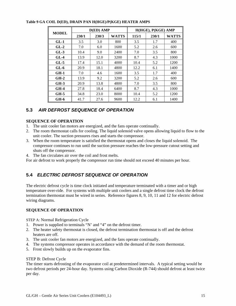
Table 9 GA COIL D(ED), DRAIN PAN H(HGE)/P(KGE) HEATER AMPS
MODEL D(ED) AMP H(HGE), P(KGE) AMP
230/1 230/3 WATTS 115/1 230/1 WATTS GL-1 3.5 3.0 800 3.5 1.7 400 GL-2 7.0 6.0 1600 5.2 2.6 600 GL-3 10.4 9.0 2400 7.0 3.5 800 GL-4 13.9 12.0 3200 8.7 4.3 1000 GL-5 17.4 15.1 4000 10.4 5.2 1200 GL-6 20.9 18.1 4800 12.2 6.1 1400 GH-1 7.0 4.6 1600 3.5 1.7 400 GH-2 13.9 9.2 3200 5.2 2.6 600 GH-3 20.9 13.8 4800 7.0 3.5 800 GH-4 27.8 18.4 6400 8.7 4.3 1000 GH-5 34.8 23.0 8000 10.4 5.2 1200 GH-6 41.7 27.6 9600 12.2 6.1 1400
5.3 AIR DEFROST SEQUENCE OF OPERATION SEQUENCE OF OPERATION 1. The unit cooler fan motors are energized, and the fans operate continually. 2. The room thermostat calls for cooling. The liquid solenoid valve opens allowing liquid to flow to the
unit cooler. The suction pressures rises and starts the compressor. 3. When the room temperature is satisfied the thermostat opens and closes the liquid solenoid. The
compressor continues to run until the suction pressure reaches the low-pressure cutout setting and shuts off the compressor.
4. The fan circulates air over the coil and frost melts. For air defrost to work properly the compressor run time should not exceed 40 minutes per hour.
5.4 ELECTRIC DEFROST SEQUENCE OF OPERATION The electric defrost cycle is time clock initiated and temperature terminated with a timer and or high temperature over-ride. For systems with multiple unit coolers and a single defrost time clock the defrost termination thermostat must be wired in series. Reference figures 8, 9, 10, 11 and 12 for electric defrost wiring diagrams. SEQUENCE OF OPERATION STEP A: Normal Refrigeration Cycle 1. Power is supplied to terminals “N’ and “4” on the defrost timer. 2. The heater safety thermostat is closed, the defrost termination thermostat is off and the defrost
heaters are off. 3. The unit cooler fan motors are energized, and the fans operate continually. 4. The systems compressor operates in accordance with the demand of the room thermostat. 5. Frost slowly builds up on the evaporator fins. STEP B: Defrost Cycle The timer starts defrosting of the evaporator coil at predetermined intervals. A typical setting would be two defrost periods per 24-hour day. Systems using Carbon Dioxide (R-744) should defrost at least twice per day.

GL/GH – Gentle Air Series Unit Coolers (E104493_L) 16
1. Upon initiation of the defrost cycle, the timer mechanically disconnects power to terminal “4” thus closing the liquid line solenoid valve and shutting off the fan motors. Simultaneously power is connected to terminal “3” which allows current to flow to the defrost heaters.
2. The heaters, embedded in slots in the coil face, give up heat directly to the evaporator fins. This heat raises the coil temperature to 32°F causing the frost to melt.
3. As the frost melts it drops into the heated drain pan and flows down the drain. 4. When the frost has completely melted from the coil the temperature of the coil will start to rise
above 32°F. 5. When the coil reaches the temperature setting of the defrost termination thermostat (75°F for fixed
Klixon), the thermostat closes which allows current to flow to terminal “X” on the timer which energizes the switching solenoid in the timer. The timer disconnects power to terminal “3” thus turning off the defrost heaters. At the same, instant power is connected to terminal “4” of the timer.
6. With power at terminal “4” the liquid line solenoid opens and the compressor restarts. 7. The evaporator fan motor(s) restart. The unit is now back in operation. 8. The heater safety thermostat will only open if the defrost termination thermostat fails to close at its
set temperature. The heater safety thermostat is set to open at 80°F. The timer also has a fail-safe (inner dial) timeout; the recommended setting is for 30 minutes.
5.5 TWO SPEED MOTOR SEQUENCE OF OPERATION –
Two speed EC motors will operate full speed without a control signal. A voltage input signal (same, voltage as fan power) to a third terminal on the motor will change operation to low speed. Fans will be operating full speed, low speed or turned off based on these scenarios.
Fans Full speed • When room temperature is above the setpoint
When in refrigeration when connected to a condensing unitFans Low Speed • When the room temperature or refrigeration setpoint is met • When not in refrigeration
Fans off • During gas or electric defrost A field or factory installed thermostat are two options for two speed fan control. available to provide a relay closure when room temperature is below setpoint. When using a thermostat, the SPDT relay on the thermostat will open when the room temperature is above the setpoint and will not supply voltage signal for low speed to the motor. When the room temperature is below the setpoint, the SPDT relay of the thermostat will close and send the voltage signal through the wiring harness to the motor to run at low speed. When using a controller, the motor low speed is controlled through a relay. Control should close the relay to supply the low speed voltage signal for low speed operation based on logic within the controller. Wiring Connections – 2 Speed motors will have 3 wires - Black, White and Red wires out of which black and white wires will be always wired to terminal pin 7&4 for fan power. The red wire which is named as control harness is connected to terminal 8. A voltage signal to terminal pin 8, will run in motors in low speed.
5.6 VARIABLE SPEED MOTOR SEQUENCE OF OPERATION
Variable speed motors require a 0-10V signal for fan speed control that provides 20mA per fan. Control signal will be wired to terminal AO+ & AO-. A 0V or no signal will operate fans at full speed. Increasing the voltage signal will decrease fan speed with minimum speed operation with a 10V signal.

GL/GH – Gentle Air Series Unit Coolers (E104493_L) 17
5.7 Air Defrost Models Wiring Diagrams Figure 6a Air Defrost Wiring Diagram for – Motor Type B
Figure 6b. Air Defrost Wiring Diagram for – Motor Type V
Figure 6c. Air Defrost Wiring Diagram for – Motor Type D

GL/GH – Gentle Air Series Unit Coolers (E104493_L) 18
Figure 7a. Air Defrost Wiring Diagram with timer - Motor Type B
Figure 7b. Air Defrost Wiring Diagram with timer - Motor Type V
Figure 7c. Air Defrost Wiring Diagram with timer - Motor Type D

GL/GH – Gentle Air Series Unit Coolers (E104493_L) 19
5.8 Electric Defrost Models Wiring Diagrams Figure 8a. Electric Defrost System with Timer Wiring - Motor Type B
Figure 8b. Electric Defrost System with Timer Wiring - Motor Type V

GL/GH – Gentle Air Series Unit Coolers (E104493_L) 20
Figure 8c. Electric Defrost System with Timer Wiring - Motor Type D
Figure 9a. Electric Defrost with Timer & Defrost Contractor Wiring - Motor Type B

GL/GH – Gentle Air Series Unit Coolers (E104493_L) 21
Figure 9b. Electric Defrost with Timer & Defrost Contractor Wiring - Motor Type V
Figure 9c. Electric Defrost with Timer & Defrost Contractor Wiring - Motor Type D

GL/GH – Gentle Air Series Unit Coolers (E104493_L) 22
Figure 10a. Electric Defrost System Wiring Motor Type B - 3 Phase Heaters
Figure 10b. Electric Defrost System Wiring Motor Type V - 3 Phase Heaters

GL/GH – Gentle Air Series Unit Coolers (E104493_L) 23
Figure 10c. Electric Defrost System Wiring Motor Type D Motor - 3 Phase Heaters
Figure 11a. Electric Defrost System Wiring Motor Type B – Multiple Evaporators
When defrosting two or more units at one time with a single time clock, the defrost termination thermostats must be wired in series as shown in Figure 5C below.

GL/GH – Gentle Air Series Unit Coolers (E104493_L) 24
Figure 11b. Electric Defrost System Wiring Motor Type V – Multiple Evaporators
Figure 11c. Electric Defrost System Wiring Motor Type D – Multiple Evaporators
GL/GH – Gentle Air Series Unit Coolers (E104493_L) 25
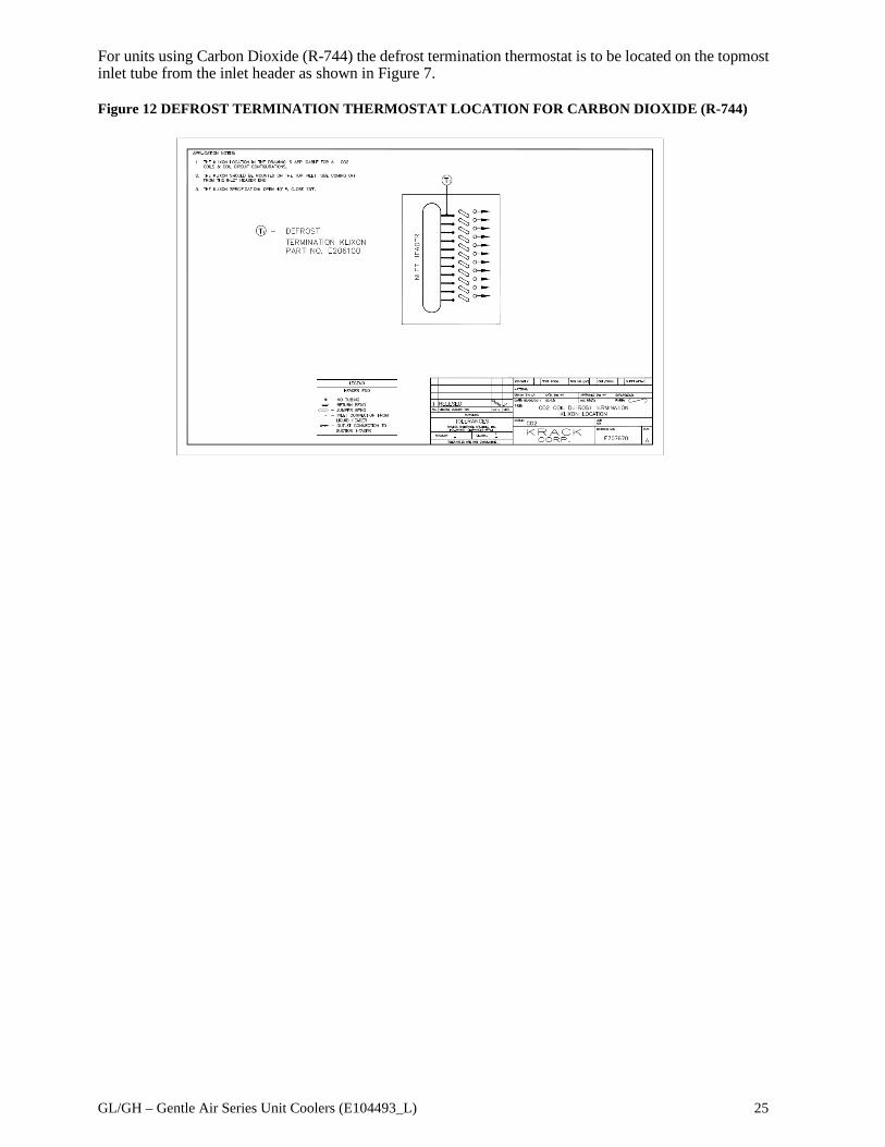
For units using Carbon Dioxide (R-744) the defrost termination thermostat is to be located on the topmost inlet tube from the inlet header as shown in Figure 7. Figure 12 DEFROST TERMINATION THERMOSTAT LOCATION FOR CARBON DIOXIDE (R-744)
GL/GH – Gentle Air Series Unit Coolers (E104493_L) 26
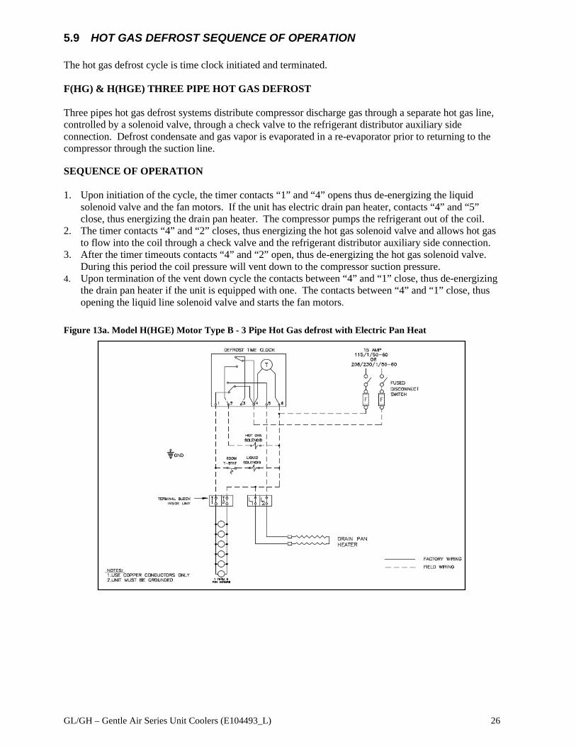
5.9 HOT GAS DEFROST SEQUENCE OF OPERATION The hot gas defrost cycle is time clock initiated and terminated. F(HG) & H(HGE) THREE PIPE HOT GAS DEFROST Three pipes hot gas defrost systems distribute compressor discharge gas through a separate hot gas line, controlled by a solenoid valve, through a check valve to the refrigerant distributor auxiliary side connection. Defrost condensate and gas vapor is evaporated in a re-evaporator prior to returning to the compressor through the suction line. SEQUENCE OF OPERATION 1. Upon initiation of the cycle, the timer contacts “1” and “4” opens thus de-energizing the liquid
solenoid valve and the fan motors. If the unit has electric drain pan heater, contacts “4” and “5” close, thus energizing the drain pan heater. The compressor pumps the refrigerant out of the coil.
2. The timer contacts “4” and “2” closes, thus energizing the hot gas solenoid valve and allows hot gas to flow into the coil through a check valve and the refrigerant distributor auxiliary side connection.
3. After the timer timeouts contacts “4” and “2” open, thus de-energizing the hot gas solenoid valve. During this period the coil pressure will vent down to the compressor suction pressure.
4. Upon termination of the vent down cycle the contacts between “4” and “1” close, thus de-energizing the drain pan heater if the unit is equipped with one. The contacts between “4” and “1” close, thus opening the liquid line solenoid valve and starts the fan motors.
Figure 13a. Model H(HGE) Motor Type B - 3 Pipe Hot Gas defrost with Electric Pan Heat

GL/GH – Gentle Air Series Unit Coolers (E104493_L) 27
Figure 13b. Model H(HGE) Motor Type V - 3 Pipe Hot Gas defrost with Electric Pan Heat
Figure 13c. Model H(HGE) Motor Type D - 3 Pipe Hot Gas defrost with Electric Pan

GL/GH – Gentle Air Series Unit Coolers (E104493_L) 28
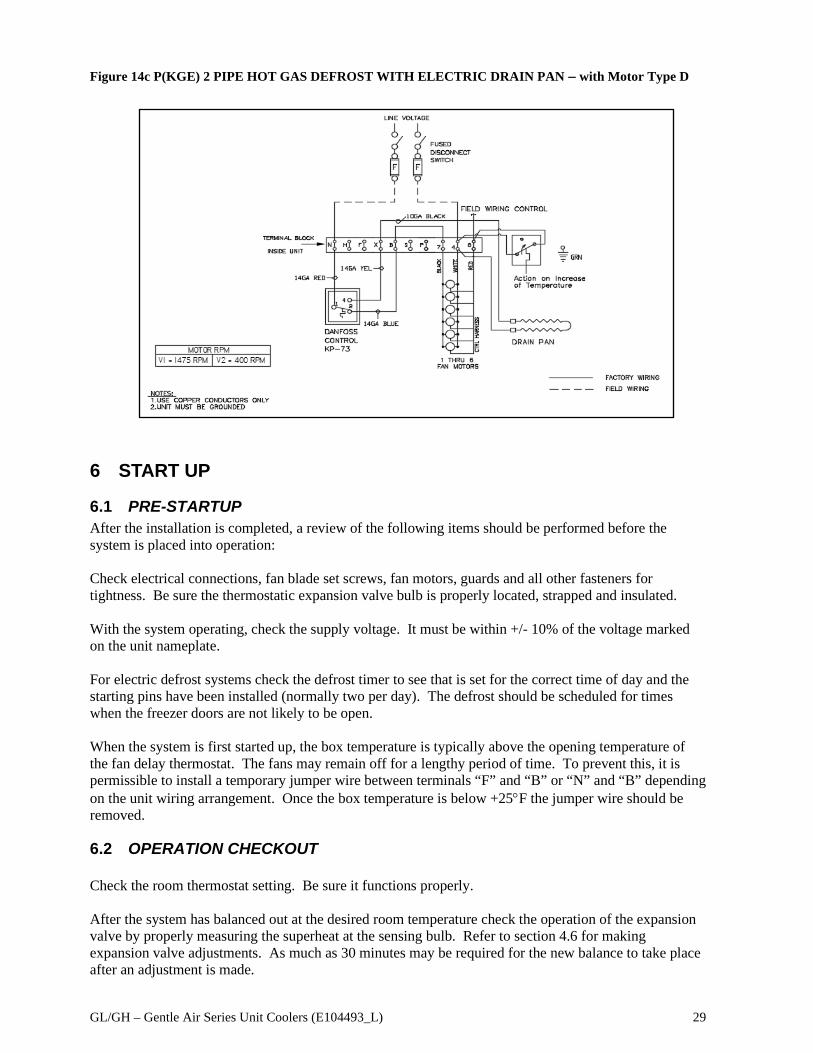
SEQUENCE OF OPERATION – M(KG) & P(KGE) REVERSE CYCLE 2 PIPE HOT GAS DEFROST Reverse cycle (2 pipe) defrost systems distribute compressor discharge gas through the suction line during defrost. Defrost condensate flows through the refrigerant distributor auxiliary side connection and a check valve, bypassing the expansion valve and the liquid line solenoid valve into the liquid line, which is reduced in pressure. 1. Power is supplied to the unit cooler continuously. 2. Hot gas is supplied to the unit via the suction line. A factory-mounted thermostat senses a rise in
coil temperature. The SPDT control turns off the fan motors. If the unit has a drain pan heater, the other portion of the SPDT control is now closed and the drain pan heater is energized.
3. When the defrost is complete the hot gas supply is stopped. The liquid line solenoid is energized, and the coil temperature begins to fall.
4. The factory-mounted thermostat senses the drop-in coil temperature. The SPDT thermostat opens the circuit to the drain pan heater (when supplied) and closed the circuit to the fan motors.
Figure 14a P(KGE) 2 PIPE HOT GAS DEFROST WITH ELECTRIC DRAIN PAN – with Motor Type B
Figure 14b P(KGE) 2 PIPE HOT GAS DEFROST WITH ELECTRIC DRAIN PAN – with Motor Type V
GL/GH – Gentle Air Series Unit Coolers (E104493_L) 29
Figure 14c P(KGE) 2 PIPE HOT GAS DEFROST WITH ELECTRIC DRAIN PAN – with Motor Type D
6 START UP
6.1 PRE-STARTUP After the installation is completed, a review of the following items should be performed before the system is placed into operation: Check electrical connections, fan blade set screws, fan motors, guards and all other fasteners for tightness. Be sure the thermostatic expansion valve bulb is properly located, strapped and insulated. With the system operating, check the supply voltage. It must be within +/- 10% of the voltage marked on the unit nameplate. For electric defrost systems check the defrost timer to see that is set for the correct time of day and the starting pins have been installed (normally two per day). The defrost should be scheduled for times when the freezer doors are not likely to be open.
When the system is first started up, the box temperature is typically above the opening temperature of the fan delay thermostat. The fans may remain off for a lengthy period of time. To prevent this, it is permissible to install a temporary jumper wire between terminals “F” and “B” or “N” and “B” depending on the unit wiring arrangement. Once the box temperature is below +25°F the jumper wire should be removed.
6.2 OPERATION CHECKOUT Check the room thermostat setting. Be sure it functions properly. After the system has balanced out at the desired room temperature check the operation of the expansion valve by properly measuring the superheat at the sensing bulb. Refer to section 4.6 for making expansion valve adjustments. As much as 30 minutes may be required for the new balance to take place after an adjustment is made.

GL/GH – Gentle Air Series Unit Coolers (E104493_L) 30
On electric defrost systems once the coil is frosted, manually advance the defrost timer to initiate a defrost. Observe the defrost cycle to see if all controls are functioning properly and that the coil is clear of all frost before the system returns to refrigeration. Reset the defrost timer to the correct time of day. A defrost cycle is only needed when the frost builds up is such that is impedes the airflow through the coil. The defrost requirements will vary on each installation and may change depending on the time of the year and other conditions.
7 PREVENTATIVE MAINTENANCE A preventative maintenance schedule should be set up as soon as the Unit Cooler is installed. The unit should be inspected periodically for proper operation and buildup of soil 1. Inspect and clean the drain pan to insure free drainage of condensate. The drain pan should be
cleaned regularly with warm water and soap. 2. The cabinet, fans and guards can be cleaned with warm water and soap. 3. The evaporator coil should be checked once a month for proper defrosting. Many variables affect
coil frosting such as room temperature, type of product being stored, how often new product is brought in and the length of time the door to the room remains open. Summer conditions of high humidity can cause heavier frost loads. It may be necessary to change the numbers of defrost cycles seasonally.
4. At least every six months check all fan motors. Tighten motor mounting screws and fan set screws. WARNING: All power to the evaporator must be off before opening any compartments, cleaning or performing maintenance.
8 TROUBLESHOOTING CHART Table 10 TROUBLESHOOTING CHARTS
PROBLEM POSSIBLE CAUSES CORRECTIVE ACTION Fans will not operate. Unit not wired properly.
Defective motor. Defective defrost timer, termination thermostat or fan delay switch.
Check wiring. Replace motor. Replace defective component.
Ice forming on ceiling. Steaming during defrost.
Too many defrosts per day. Defective termination Thermostat or defrost timer.
Observe frost build up on coil, change to fewer defrost per day. Replace defective component.
Excessive buildup of frost on coil.
Too few defrost times. Defrost cycle too short. Too high humidity in cooler.
Add more defrost cycles to timer. Extend defrost time on timer. Limit access to cooler, do not prop doors open during stocking.
Accumulation of ice in drain pan.
Drain line plugged. Defective heater.
Clean drain line. Make sure drain line is insulated properly. Replace heater.

GL/GH – Gentle Air Series Unit Coolers (E104493_L) 31
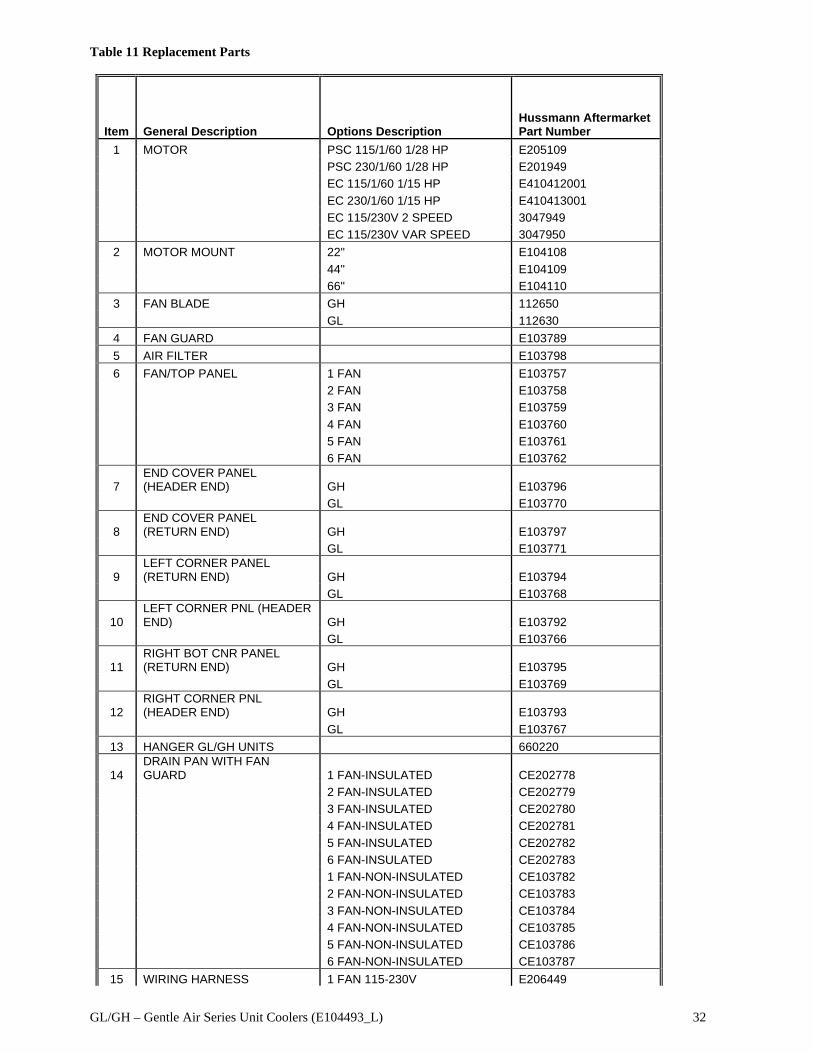
9 REPLACEMENT PARTS LIST Listed below are the major replacement parts. When ordering parts, it is imperative that you obtain the complete model and serial number of the unit.
Figure 15 REPLACEMENT PARTS
GL/GH – Gentle Air Series Unit Coolers (E104493_L) 32
Table 11 Replacement Parts
Item General Description Options Description Hussmann Aftermarket Part Number
1 MOTOR PSC 115/1/60 1/28 HP E205109 PSC 230/1/60 1/28 HP E201949 EC 115/1/60 1/15 HP E410412001 EC 230/1/60 1/15 HP E410413001 EC 115/230V 2 SPEED 3047949 EC 115/230V VAR SPEED 3047950
2 MOTOR MOUNT 22" E104108 44" E104109 66" E104110 3 FAN BLADE GH 112650 GL 112630 4 FAN GUARD E103789 5 AIR FILTER E103798 6 FAN/TOP PANEL 1 FAN E103757 2 FAN E103758 3 FAN E103759 4 FAN E103760 5 FAN E103761 6 FAN E103762
7 END COVER PANEL (HEADER END) GH E103796
GL E103770
8 END COVER PANEL (RETURN END) GH E103797
GL E103771
9 LEFT CORNER PANEL (RETURN END) GH E103794
GL E103768
10 LEFT CORNER PNL (HEADER END) GH E103792
GL E103766
11 RIGHT BOT CNR PANEL (RETURN END) GH E103795
GL E103769
12 RIGHT CORNER PNL (HEADER END) GH E103793
GL E103767 13 HANGER GL/GH UNITS 660220
14 DRAIN PAN WITH FAN GUARD 1 FAN-INSULATED CE202778
2 FAN-INSULATED CE202779 3 FAN-INSULATED CE202780 4 FAN-INSULATED CE202781 5 FAN-INSULATED CE202782 6 FAN-INSULATED CE202783 1 FAN-NON-INSULATED CE103782 2 FAN-NON-INSULATED CE103783 3 FAN-NON-INSULATED CE103784 4 FAN-NON-INSULATED CE103785 5 FAN-NON-INSULATED CE103786 6 FAN-NON-INSULATED CE103787
15 WIRING HARNESS 1 FAN 115-230V E206449

GL/GH – Gentle Air Series Unit Coolers (E104493_L) 33
2 FAN 115-230V E206450 3 FAN 115-230V E206451 4 FAN 115-230V E206452 5 FAN 115-230V E206453 6 FAN 115-230V E206454 1 FAN 460V E206518 2 FAN 460V E206519 3 FAN 460V E206520 4 FAN 460V E206521 5 FAN 460V E206522 6 FAN 460V E206523 2 SPEED HARNESS HARNESS-2SP 1 FAN 3105724 HARNESS-2SP 2 FAN 3105725 HARNESS-2SP 3 FAN 3105726 HARNESS-2SP 4 FAN 3105727 HARNESS-2SP 5 FAN 3105728 HARNESS-2SP 6 FAN 3105729 VARIABLE SPEED HARNESS HARNESS-VS 1 FAN 3086202 HARNESS-VS 2 FAN 3086203 HARNESS-VS 3 FAN 3086204 HARNESS-VS 4 FAN 3086205 HARNESS-VS 5 FAN 3086206 HARNESS-VS 6 FAN 3086207
16 THERMOSTATS DEFROST TERMINATION THERMOSTAT FIXED (KLIXON) E206100
HEATER SAFETY THERMOSTAT 109560
HEATER SAFETY THERMOSTAT SPDT E206465
FAN DELAY E201818 KP-73 E205004 FAN SPEED CONTROLS 2 SPEED POWER SUPPLY 3115218 VAR SPEED CONTROL - KE2 3069208
17 PAN HEATERS 115/230/1/60, 1 FAN 631080 115/230/1/60, 2 FAN 631090 115/230/1/60, 3 FAN 631100 115/230/1/60, 4 FAN 631110 115/230/1/60, 5 FAN 631120 115/230/1/60, 6 FAN 631130
18 COIL HEATERS 230V, 1 FAN E101930 460V, 1 FAN E101936 230V, 2 FAN E101931 460V, 2 FAN E101937 230V, 3 FAN E101932 460V, 3 FAN E101938 230V, 4 FAN E101933 460V, 4 FAN E101939 230V, 5 FAN E101934 460V, 5 FAN E101940 230V, 6 FAN E101935 460V, 6 FAN E101941
19 FACE HEATER CLIP E102007 20 BOTTOM HEATER SUPPORT E205740 21 CHECK VALVE 118520 118530
22 EXPANSION VALVE EBSJE-5-C E206822

GL/GH – Gentle Air Series Unit Coolers (E104493_L) 34
EBSSE-6-C E314439 EGJE-1/2-C E205915 EGJE-1/4-C E206474 EGJE-1-1/2-C E206131 EGJE-1-C E205916 EGJE-2-C E205987 EGSE-1/2-C E205984 EGSE-1/4-C E206277 EGSE-1-1/2-C E205983 EGSE-1-C E205982 EGSE-2-C E205985 EGVE-1/2-C E205717 EGVE-1-1/2-C E205723 EGVE-1-C E205721 EGVE-2-C E205781 EGVE-3/4-C E205719 EGVE-3-C E205803 SBFJE-AA-C E205991 SBFJE-A-C E205992 SBFJE-B-C E205993 SBFJE-C-C E205994 SBFSE-AA-C E206015 SBFSE-A-C E206013 SBFSE-B-C E206014 SBFSE-C-C E206016 SBFVE-AA-C E205501 SBFVE-A-C E311117 SBFVE-B-C E205500 SBFVE-C-C E311118
GL/GH – Gentle Air Series Unit Coolers (E104493_L) 35
NOTES:

GL/GH – Gentle Air Series Unit Coolers (E104493_L) 36