household & commercial circuit boards...culligan household and commercial circuit boards models...
TRANSCRIPT
Rev. A 09/24/02
DCO# 4541
Cat. No. 01015170
HHOOUUSSEEHHOOLLDD &&
CCOOMMMMEERRCCIIAALL
CCIIRRCCUUIITT BBOOAARRDDSSModels From 1994 - 2002
©2002 Culligan International Company Printed in U.S.A.
Service
Manual
CCuulllliiggaann HHoouusseehhoolldd aanndd CCoommmmeerrcciiaall CCiirrccuuiitt BBooaarrddssMMooddeellss FFrroomm 11999944 -- 22000022
TABLE OF CONTENTS
Culligan Medallist Series™ Circuit Board Page 1
Culligan® Mark 100 Generation I Circuit Board Page 9
Culligan® Mark 100 Generation II/ Culligan Platinum Series™ Generation I Circuit Board Page 14
Culligan® Mark 100 Generation III, Culligan Silver Series™, Culligan Gold Series™
and Culligan® Platinum Series™ Generation II Circuit Boards Page 21
Upgrade Kit to Convert Culligan® Mark 100 Generation I Circuit Board to
Culligan® Mark 100 Generation III Circuit Board Page 27
Culligan® Aqua-Sensor® Sensing Device Troubleshooting Guide Page 29
Culligan® Mark 10/Estate 2M Generation I Circuit Board Page 33
Culligan® Mark 10/Estate 2M Generation II Circuit Board Page 35
Upgrade Kit to Convert Culligan Mark 10/Estate 2M Generation I Circuit Board to
Culligan Mark 10/Estate 2M Generation II Circuit Board Page 37
Culligan® Commercial Circuit Board - Generation I Page 41
Culligan® Commercial Circuit Board - Generation II Page 50
For additional information please refer to the Installation and Operation Manual
and/or the Service Manual for the above units.
CULLIGAN HOUSEHOLD & COMMERCIAL CIRCUIT BOARDSi
WARNING! PRIOR TO SERVICING EQUIPMENT, DISCONNECT POWER
SUPPLY TO PREVENT ELECTRICAL SHOCK
WARNING! IF INCORRECTLY INSTALLED, OPERATED OR MAINTAINED,
THIS PRODUCT CAN CAUSE SEVERE INJURY. THOSE WHO INSTALL,
OPERATE, OR MAINTAIN THIS PRODUCT SHOULD BE TRAINED IN IT’S
PROPER USE, WARNED OF IT’S DANGERS, AND SHOULD READ THE ENTIRE
MANUAL BEFORE ATTEMPTING TO INSTALL, OPERATE OR MAINTAIN THIS
PRODUCT.
CULLIGAN HOUSEHOLD & COMMERCIAL CIRCUIT BOARDS 1
CCuulllliiggaann MMeeddaalllliisstt SSeerriieess™ CCiirrccuuiitt BBooaarrdd
Used from 1/01 to Current
Replacement PN: 01014172
Control Functions
Function Time Clock Soft-Minder Meter Default
Time of Day YES YES 12:00 p.m.
Time of Regen. YES YES 2:00 a.m.
Salt Dosage YES YES 10 lbs.
Backwash Time YES YES 10 min.
Brine Rinse Time YES YES 71 min
Gallons Capacity/Regen. Interval YES YES 870 gallons or 3 days
Forced Regen. Interval NO YES* disabled
Lock/Unlock display YES YES disabled
* When Time Clock Backup is set to "ON".
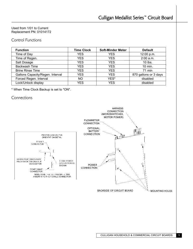
Connections
CULLIGAN HOUSEHOLD & COMMERCIAL CIRCUIT BOARDS2
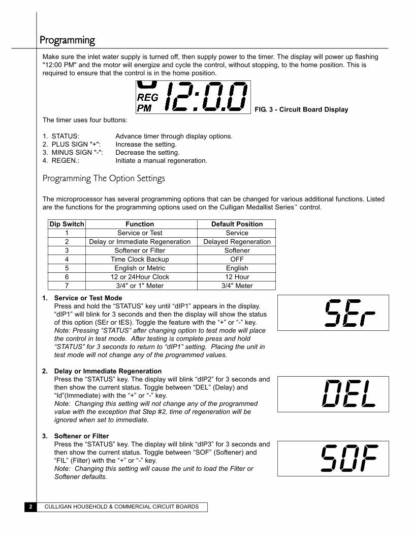
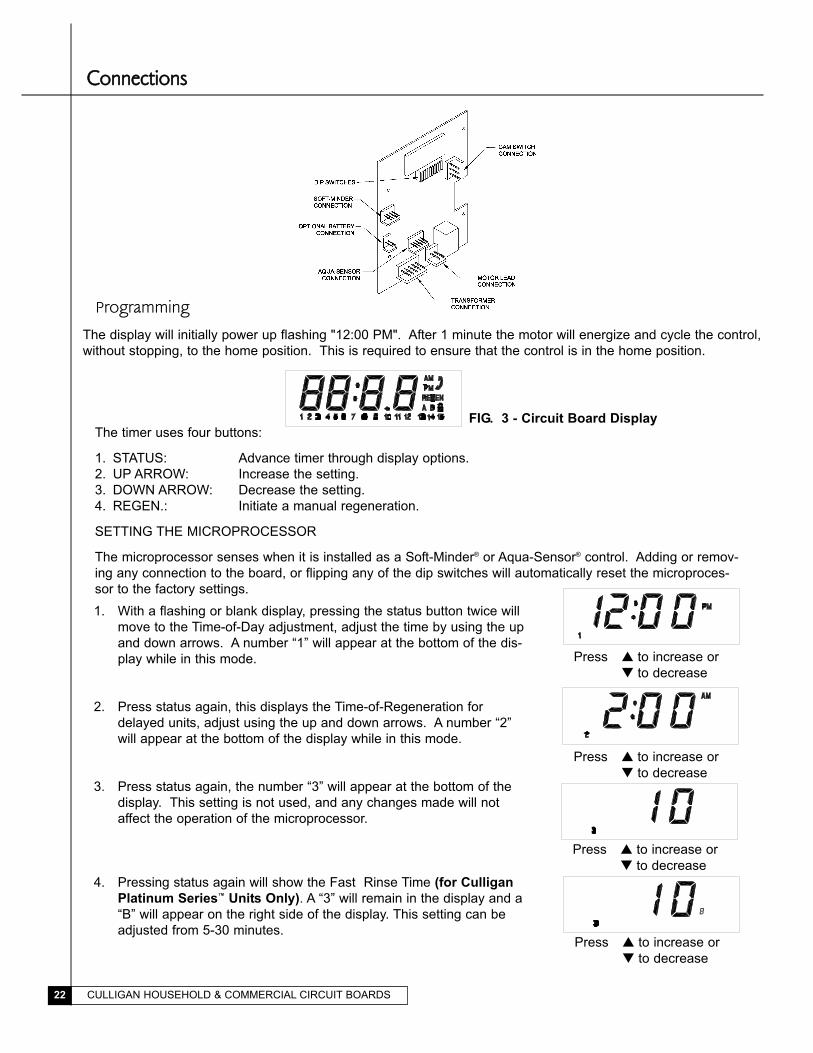
FIG. 3 - Circuit Board Display
PPrrooggrraammmmiinngg
Make sure the inlet water supply is turned off, then supply power to the timer. The display will power up flashing
"12:00 PM" and the motor will energize and cycle the control, without stopping, to the home position. This is
required to ensure that the control is in the home position.
The timer uses four buttons:
1. STATUS: Advance timer through display options.
2. PLUS SIGN "+": Increase the setting.
3. MINUS SIGN "-": Decrease the setting.
4. REGEN.: Initiate a manual regeneration.
Programming The Option Settings
The microprocessor has several programming options that can be changed for various additional functions. Listed
are the functions for the programming options used on the Culligan Medallist Series™ control.
Dip Switch Function Default Position
1 Service or Test Service
2 Delay or Immediate Regeneration Delayed Regeneration
3 Softener or Filter Softener
4 Time Clock Backup OFF
5 English or Metric English
6 12 or 24Hour Clock 12 Hour
7 3/4" or 1" Meter 3/4" Meter
DEL
SOF
1. Service or Test Mode
Press and hold the “STATUS” key until “dIP1” appears in the display.
“dIP1” will blink for 3 seconds and then the display will show the status
of this option (SEr or tES). Toggle the feature with the “+” or “-” key.
Note: Pressing “STATUS” after changing option to test mode will place the control in test mode. After testing is complete press and hold“STATUS” for 3 seconds to return to “dIP1” setting. Placing the unit in test mode will not change any of the programmed values.
2. Delay or Immediate Regeneration
Press the “STATUS” key. The display will blink “dIP2” for 3 seconds and
then show the current status. Toggle between “DEL” (Delay) and
“Id”(Immediate) with the “+” or “-” key.
Note: Changing this setting will not change any of the programmed value with the exception that Step #2, time of regeneration will be ignored when set to immediate.
3. Softener or Filter
Press the “STATUS” key. The display will blink “dIP3” for 3 seconds and
then show the current status. Toggle between “SOF” (Softener) and
“FIL” (Filter) with the “+” or “-” key.
Note: Changing this setting will cause the unit to load the Filter or Softener defaults.
CULLIGAN HOUSEHOLD & COMMERCIAL CIRCUIT BOARDS 3
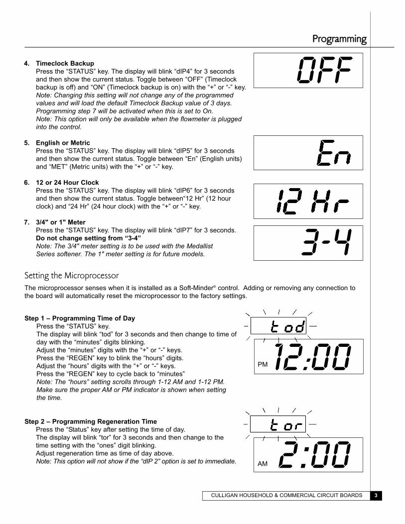
OFF4. Timeclock Backup
Press the “STATUS” key. The display will blink “dIP4” for 3 seconds
and then show the current status. Toggle between “OFF” (Timeclock
backup is off) and “ON” (Timeclock backup is on) with the “+” or “-” key.
Note: Changing this setting will not change any of the programmed values and will load the default Timeclock Backup value of 3 days.Programming step 7 will be activated when this is set to On.Note: This option will only be available when the flowmeter is pluggedinto the control.
5. English or Metric
Press the “STATUS” key. The display will blink “dIP5” for 3 seconds
and then show the current status. Toggle between “En” (English units)
and “MET” (Metric units) with the “+” or “-” key.
6. 12 or 24 Hour Clock
Press the “STATUS” key. The display will blink “dIP6” for 3 seconds
and then show the current status. Toggle between“12 Hr” (12 hour
clock) and “24 Hr” (24 hour clock) with the “+” or “-” key.
7. 3/4" or 1" Meter
Press the “STATUS” key. The display will blink “dIP7” for 3 seconds.
Do not change setting from “3-4”
Note: The 3/4" meter setting is to be used with the Medallist Series softener. The 1" meter setting is for future models.
12:00PM
2:00AM
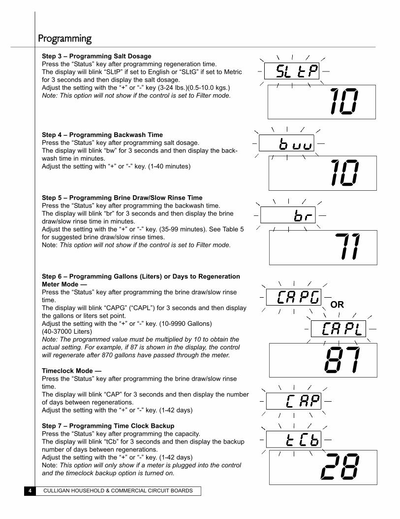
Setting the MicroprocessorThe microprocessor senses when it is installed as a Soft-Minder® control. Adding or removing any connection to
the board will automatically reset the microprocessor to the factory settings.
Step 1 – Programming Time of Day
Press the “STATUS” key.
The display will blink “tod” for 3 seconds and then change to time of
day with the “minutes” digits blinking.
Adjust the “minutes” digits with the “+” or “-” keys.
Press the “REGEN” key to blink the “hours” digits.
Adjust the “hours” digits with the “+” or “-” keys.
Press the “REGEN” key to cycle back to “minutes”
Note: The “hours” setting scrolls through 1-12 AM and 1-12 PM. Make sure the proper AM or PM indicator is shown when setting the time.
Step 2 – Programming Regeneration Time
Press the “Status” key after setting the time of day.
The display will blink “tor” for 3 seconds and then change to the
time setting with the “ones” digit blinking.
Adjust regeneration time as time of day above.
Note: This option will not show if the “dIP 2” option is set to immediate.
PPrrooggrraammmmiinngg
3-4
CULLIGAN HOUSEHOLD & COMMERCIAL CIRCUIT BOARDS4
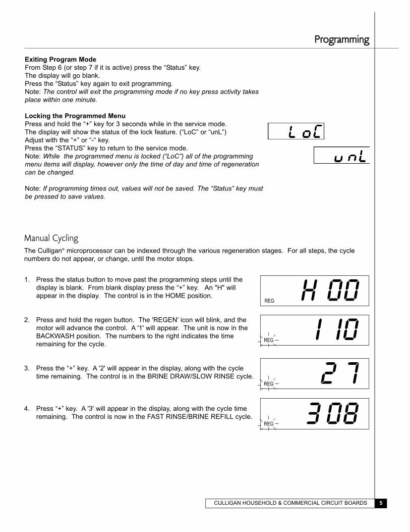
Step 3 – Programming Salt Dosage
Press the “Status” key after programming regeneration time.
The display will blink “SLtP” if set to English or “SLtG” if set to Metric
for 3 seconds and then display the salt dosage.
Adjust the setting with the “+” or “-” key (3-24 lbs.)(0.5-10.0 kgs.)
Note: This option will not show if the control is set to Filter mode.
Step 4 – Programming Backwash Time
Press the “Status” key after programming salt dosage.
The display will blink “bw” for 3 seconds and then display the back-
wash time in minutes.
Adjust the setting with “+” or “-” key. (1-40 minutes)
Step 5 – Programming Brine Draw/Slow Rinse Time
Press the “Status” key after programming the backwash time.
The display will blink “br” for 3 seconds and then display the brine
draw/slow rinse time in minutes.
Adjust the setting with the “+” or “-” key. (35-99 minutes). See Table 5
for suggested brine draw/slow rinse times.
Note: This option will not show if the control is set to Filter mode.
Step 6 – Programming Gallons (Liters) or Days to Regeneration
Meter Mode —
Press the “Status” key after programming the brine draw/slow rinse
time.
The display will blink “CAPG” (“CAPL”) for 3 seconds and then display
the gallons or liters set point.
Adjust the setting with the “+” or “-” key. (10-9990 Gallons)
(40-37000 Liters)
Note: The programmed value must be multiplied by 10 to obtain theactual setting. For example, if 87 is shown in the display, the controlwill regenerate after 870 gallons have passed through the meter.
Timeclock Mode —
Press the “Status” key after programming the brine draw/slow rinse
time.
The display will blink “CAP” for 3 seconds and then display the number
of days between regenerations.
Adjust the setting with the “+” or “-” key. (1-42 days)
Step 7 – Programming Time Clock Backup
Press the “Status” key after programming the capacity.
The display will blink “tCb” for 3 seconds and then display the backup
number of days between regenerations.
Adjust the setting with the “+” or “-” key. (1-42 days)
Note: This option will only show if a meter is plugged into the controland the timeclock backup option is turned on.
10
71
87
28
10
OR
PPrrooggrraammmmiinngg
CULLIGAN HOUSEHOLD & COMMERCIAL CIRCUIT BOARDS 5
Exiting Program Mode
From Step 6 (or step 7 if it is active) press the “Status” key.
The display will go blank.
Press the “Status” key again to exit programming.
Note: The control will exit the programming mode if no key press activity takesplace within one minute.
Locking the Programmed Menu
Press and hold the “+” key for 3 seconds while in the service mode.
The display will show the status of the lock feature. (“LoC” or “unL”)
Adjust with the “+” or “-“ key.
Press the “STATUS” key to return to the service mode.
Note: While the programmed menu is locked (“LoC”) all of the programmingmenu items will display, however only the time of day and time of regenerationcan be changed.
Note: If programming times out, values will not be saved. The “Status” key mustbe pressed to save values.
Manual CyclingThe Culligan® microprocessor can be indexed through the various regeneration stages. For all steps, the cycle
numbers do not appear, or change, until the motor stops.
1. Press the status button to move past the programming steps until the
display is blank. From blank display press the “+” key. An "H" will
appear in the display. The control is in the HOME position.
2. Press and hold the regen button. The 'REGEN' icon will blink, and the
motor will advance the control. A '1' will appear. The unit is now in the
BACKWASH position. The numbers to the right indicates the time
remaining for the cycle.
3. Press the “+” key. A '2' will appear in the display, along with the cycle
time remaining. The control is in the BRINE DRAW/SLOW RINSE cycle.
4. Press “+” key. A '3' will appear in the display, along with the cycle time
remaining. The control is now in the FAST RINSE/BRINE REFILL cycle.
H 00REG
I I0REG
2 7 REG
3 08REG
PPrrooggrraammmmiinngg
CULLIGAN HOUSEHOLD & COMMERCIAL CIRCUIT BOARDS6
H 00
7:28PM
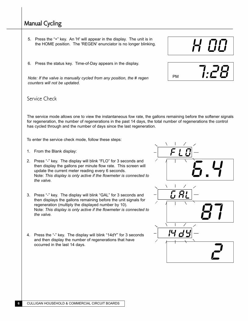
5. Press the “+” key. An 'H' will appear in the display. The unit is in
the HOME position. The 'REGEN' enunciator is no longer blinking.
6. Press the status key. Time-of-Day appears in the display.
Note: If the valve is manually cycled from any position, the # regencounters will not be updated.
Service Check
The service mode allows one to view the instantaneous fow rate, the gallons remaining before the softener signals
for regeneration, the number of regenerations in the past 14 days, the total number of regenerations the control
has cycled through and the number of days since the last regeneration.
To enter the service check mode, follow these steps:
1. From the Blank display:
2. Press “-” key. The display will blink “FLO” for 3 seconds and
then display the gallons per minute flow rate. This screen will
update the current meter reading every 6 seconds.
Note: This display is only active if the flowmeter is connected tothe valve.
3. Press “-” key. The display will blink “GAL” for 3 seconds and
then displays the gallons remaining before the unit signals for
regeneration (multiply the displayed number by 10).
Note: This display is only active if the flowmeter is connected tothe valve.
4. Press the “-” key. The display will blink “14dY” for 3 seconds
and then display the number of regenerations that have
occurred in the last 14 days.
6.4
87
2
MMaannuuaall CCyycclliinngg
CULLIGAN HOUSEHOLD & COMMERCIAL CIRCUIT BOARDS 7
93
5
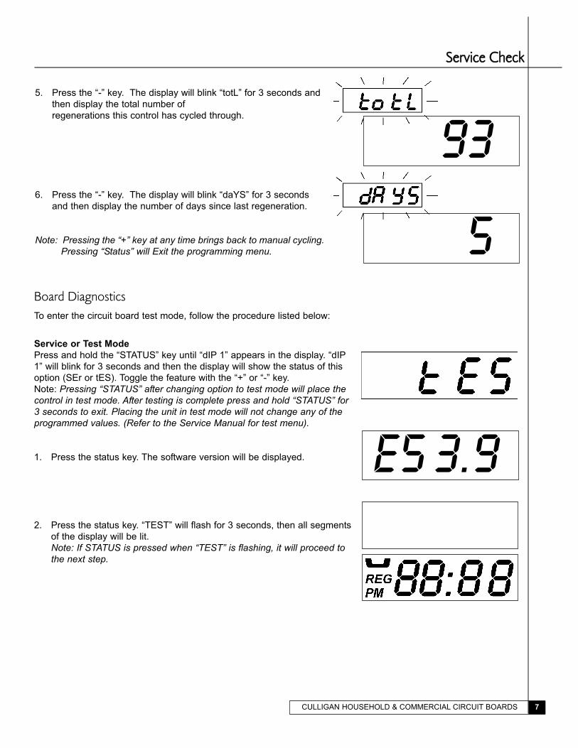
5. Press the “-” key. The display will blink “totL” for 3 seconds and
then display the total number of
regenerations this control has cycled through.
6. Press the “-” key. The display will blink “daYS” for 3 seconds
and then display the number of days since last regeneration.
Note: Pressing the “+” key at any time brings back to manual cycling.Pressing “Status” will Exit the programming menu.
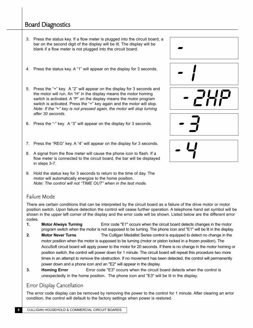
Board DiagnosticsTo enter the circuit board test mode, follow the procedure listed below:
Service or Test Mode
Press and hold the “STATUS” key until “dIP 1” appears in the display. “dIP
1” will blink for 3 seconds and then the display will show the status of this
option (SEr or tES). Toggle the feature with the “+” or “-” key.
Note: Pressing “STATUS” after changing option to test mode will place thecontrol in test mode. After testing is complete press and hold “STATUS” for3 seconds to exit. Placing the unit in test mode will not change any of theprogrammed values. (Refer to the Service Manual for test menu).
1. Press the status key. The software version will be displayed.
2. Press the status key. “TEST” will flash for 3 seconds, then all segments
of the display will be lit.
Note: If STATUS is pressed when “TEST” is flashing, it will proceed tothe next step.
E5 3.9
SSeerrvviiccee CChheecckk
CULLIGAN HOUSEHOLD & COMMERCIAL CIRCUIT BOARDS8
- 3- 4
3. Press the status key. If a flow meter is plugged into the circuit board, a
bar on the second digit of the display will be lit. The display will be
blank if a flow meter is not plugged into the circuit board.
4. Press the status key. A “1” will appear on the display for 3 seconds.
5. Press the “+” key. A “2” will appear on the display for 3 seconds and
the motor will run. An “H” in the display means the motor homing
switch is activated. A “P” on the display means the motor program
switch is activated. Press the “+” key again and the motor will stop.
Note: If the “+” key is not pressed again, the motor will stop turningafter 30 seconds.
6. Press the “-” key. A “3” will appear on the display for 3 seconds.
7. Press the “REG” key. A “4” will appear on the display for 3 seconds.
8. A signal from the flow meter will cause the phone icon to flash. If a
flow meter is connected to the circuit board, the bar will be displayed
in steps 3-7.
9. Hold the status key for 3 seconds to return to the time of day. The
motor will automatically energize to the home position.
Note: The control will not “TIME OUT” when in the test mode.
BBooaarrdd DDiiaaggnnoossttiiccss
-
- 2HP- I
Failure ModeThere are certain conditions that can be interpreted by the circuit board as a failure of the drive motor or motor
position switch. Upon failure detection the control will cease further operation. A telephone hand set symbol will be
shown in the upper left corner of the display and the error code will be shown. Listed below are the different error
codes.
1. Motor Always Turning Error code "E1" occurs when the circuit board detects changes in the motor
program switch when the motor is not supposed to be turning. The phone icon and "E1" will be lit in the display.
2. Motor Never Turns The Culligan Medallist Series control is equipped to detect no change in the
motor position when the motor is supposed to be turning (motor or piston locked in a frozen position). The
AccuSoft circuit board will apply power to the motor for 20 seconds. If there is no change in the motor homing or
position switch, the control will power down for 1 minute. The circuit board will repeat this procedure two more
times in an attempt to remove the obstruction. If no movement has been detected, the control will permanently
power down and a phone icon and an "E2" will appear in the display.
3. Homing Error Error code "E3" occurs when the circuit board detects when the control is
unexpectedly in the home position. The phone icon and "E3" will be lit in the display.
Error Display CancellationThe error code display can be removed by removing the power to the control for 1 minute. After clearing an error
condition, the control will default to the factory settings when power is restored.
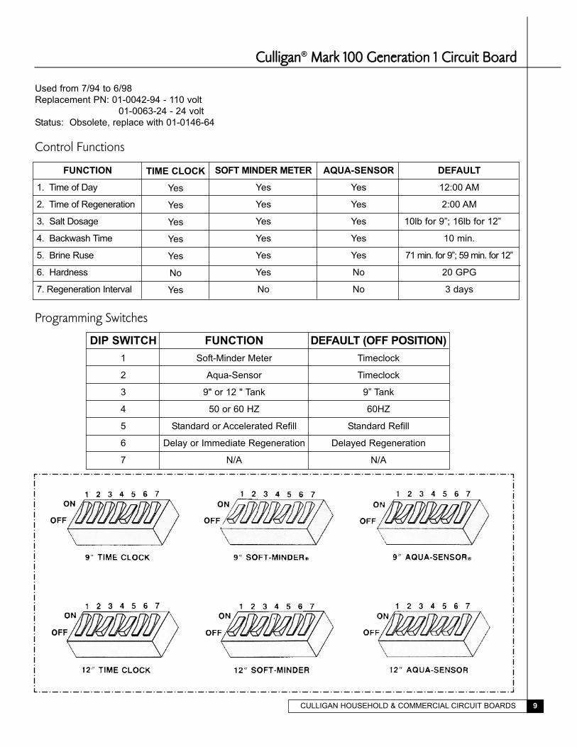
CCuulllliiggaann® MMaarrkk 110000 GGeenneerraattiioonn 11 CCiirrccuuiitt BBooaarrdd
Used from 7/94 to 6/98
Replacement PN: 01-0042-94 - 110 volt
01-0063-24 - 24 volt
Status: Obsolete, replace with 01-0146-64
Control Functions
Programming Switches
FUNCTION
1. Time of Day
2. Time of Regeneration
3. Salt Dosage
4. Backwash Time
5. Brine Ruse
6. Hardness
7. Regeneration Interval
TIME CLOCK
Yes
Yes
Yes
Yes
Yes
No
Yes
SOFT MINDER METER
Yes
Yes
Yes
Yes
Yes
Yes
No
AQUA-SENSOR
Yes
Yes
Yes
Yes
Yes
No
No
DEFAULT
12:00 AM
2:00 AM
10lb for 9”; 16lb for 12”
10 min.
71 min. for 9”; 59 min. for 12”
20 GPG
3 days
DIP SWITCH
1
2
3
4
5
6
7
FUNCTION
Soft-Minder Meter
Aqua-Sensor
9" or 12 " Tank
50 or 60 HZ
Standard or Accelerated Refill
Delay or Immediate Regeneration
N/A
DEFAULT (OFF POSITION)
Timeclock
Timeclock
9” Tank
60HZ
Standard Refill
Delayed Regeneration
N/A
CULLIGAN HOUSEHOLD & COMMERCIAL CIRCUIT BOARDS 9
CULLIGAN HOUSEHOLD & COMMERCIAL CIRCUIT BOARDS10
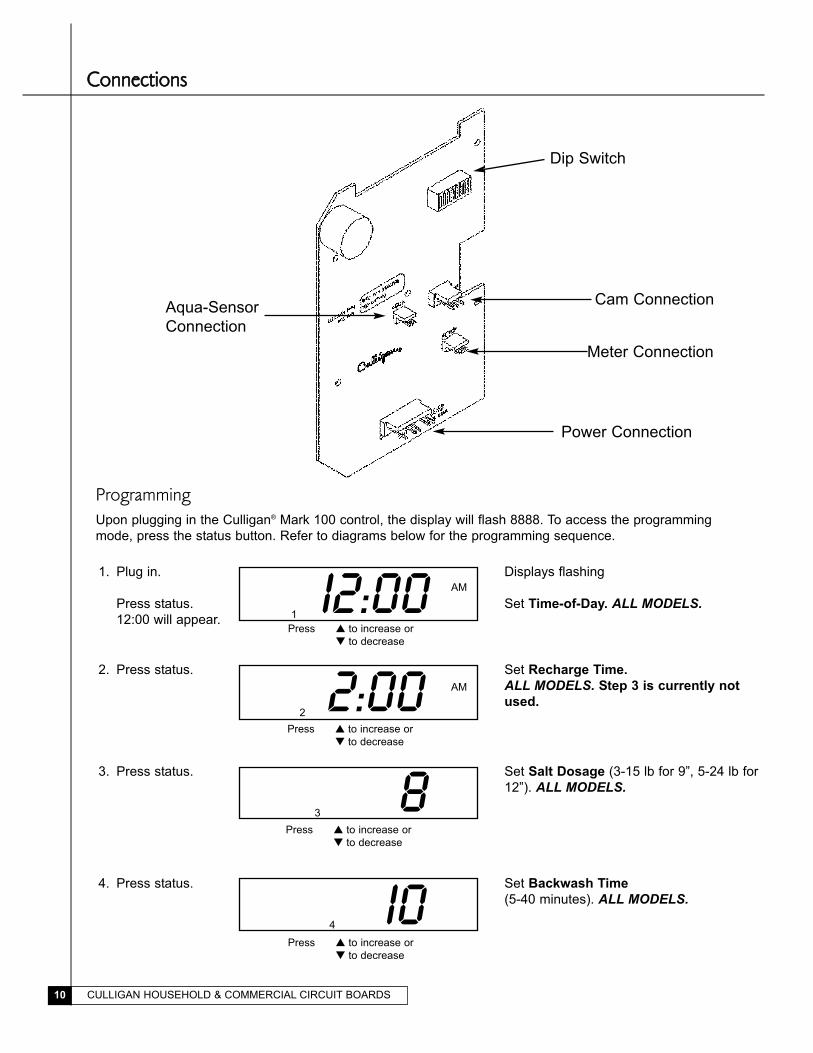
CCoonnnneeccttiioonnss
Meter Connection
Cam Connection
Dip Switch
Aqua-Sensor
Connection
Power Connection
1. Plug in.
Press status.
12:00 will appear.
AM
Displays flashing
Set Time-of-Day. ALL MODELS.I2:001
Press � to increase or
� to decrease
2. Press status.
AM
Set Recharge Time.
ALL MODELS. Step 3 is currently not
used.2:001 2
3. Press status. Set Salt Dosage (3-15 lb for 9”, 5-24 lb for
12”). ALL MODELS.81 23 3
4. Press status. Set Backwash Time
(5-40 minutes). ALL MODELS.I01 2 3 44
ProgrammingUpon plugging in the Culligan® Mark 100 control, the display will flash 8888. To access the programming
mode, press the status button. Refer to diagrams below for the programming sequence.
Press � to increase or
� to decrease
Press � to increase or
� to decrease
Press � to increase or
� to decrease

CULLIGAN HOUSEHOLD & COMMERCIAL CIRCUIT BOARDS 11
7. Press status. Set Regeneration Interval (1-42 days).
TIME CLOCK MODELS ONLY.31 2 3 4 5 6 7
5. Press status. Set Brine Rinse Time (37-85 minutes for
9”, 35-89 minutes for 12”). TIME CLOCKAND METER MODELS ONLY.7I5
6. Press status. Set Hardness Level (1-75 gpg for 9”,
1-99 gpg for 12”).
METER MODELS ONLY.201 2 3 4 5 6
Press � to increase or
� to decrease
Press � to increase or
� to decrease
Press � to increase or
� to decrease
PPrrooggrraammmmiinngg
Service Check Mode
The service check mode allows one to view the instantaneous flow rate (0.5-1.0 gpm, meter models only), The
days since the last regeneration,and the number of regenerations in the past fourteen days. To enter the service
check mode, follow these steps:
1. Press the STATUS key until the display is
blank.
2. Press the DOWN arrow. (Soft-Minder®
meter models only)
3. Press the down arrow.
4. Press the down arrow.
5. Press the STATUS key twice.
Display in blank.
Displays instantaneous flow. The
FLOW segment will be lit. An -:-
display indicates flow greater than
10.0 gpm.
Displays number of days since last
regeneration. LAST segment is lit
Displays the number of regenera-
tions within the past fourteen days.
The #REGEN segment will be lit. If
0, then no regenerations occurred
within the past fourteen days.
The display will show Time-of-Day.
FLOW 5:5
LAST 2
#REGEN 8
8:00AM
CULLIGAN HOUSEHOLD & COMMERCIAL CIRCUIT BOARDS12
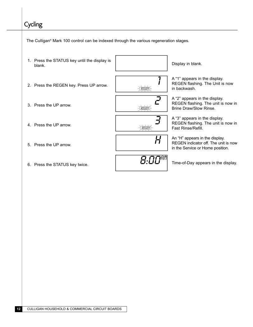
CCyycclliinngg
The Culligan® Mark 100 control can be indexed through the various regeneration stages.
1. Press the STATUS key until the display is
blank.
2. Press the REGEN key. Press UP arrow.
3. Press the UP arrow.
4. Press the UP arrow.
5. Press the UP arrow.
6. Press the STATUS key twice.
Display in blank.
A “1” appears in the display.
REGEN flashing. The Unit is now
in backwash.
A “2” appears in the display.
REGEN flashing. The unit is now in
Brine Draw/Slow Rinse.
A “3” appears in the display.
REGEN flashing. The unit is now in
Fast Rinse/Refill.
An “H” appears in the display.
REGEN indicator off. The unit is now
in the Service or Home position.
Time-of-Day appears in the display.
10
20
30
8:00AM
H0
REGEN
REGEN
REGEN

CULLIGAN HOUSEHOLD & COMMERCIAL CIRCUIT BOARDS 13
CCyycclliinngg
Failure ModeThe Culligan Mark 100 control is equipped to detect a motor or piston which is locked ina frozen position. The
AccuSoft™ circuit board will apply power to the motor for 30 seconds. If there is no change in the motor homing or
piston switch, the control will power-down for 90 seconds.
The circuit board will repeat this procedure two more times in an attempt to remove the obstruction. If no move-
ment has been detected, the power will be shut off to the motor and the display will read “CS” (Call Service). To
return to the service mode, turn power off to the unit for one full minute and remove the obstruction to the motor or
the piston.
Board Diagnostic
To enter the board test mode, shift the Aqua-Sensor® sensing device and the Soft-Minder® meter dip switches (#1
and #2) to the ON position (upwards). The display will initially light up all segments until either a key is depressed,
an option is changed, or a CAM microswitch changes position. Pressing one of the keys, closing a microswitch, or
turning on a dip switch will light a different segment as outlined in table 3.
For units equipped with a flow meter, a water
flow will cause the 1-7 segments to light individ-
ually in a sequential order. The faster the flow
rate, the quicker the sequence.
A balance signal should be applied to the Aqua-
Sensor® pin connector. This can be done with a
set of resistors or with a clean Aqua-Sensor
probe and a fully regenerated bed.
An unbalanced signal will cause the drive motor
to run continuously. A balanced signal will cause
the motor to stop.
This test can be used to check the integrity of
the Aqua-Sensor probe. If the probe is connect-
ed to the board and the drive motor runs contin-
uously, the probe should be cleaned and
checked.
Turning on two DIP switches other that DIP
switches 1 and 3 will cause a dash followed by
a number to appear. This ia the version number
of the software contained in the microprocessor.
Table 3
Action Segment
Status Key “Low Salt”
Up Key “Regen”
Down Key “Flow”
Regen key “Last”
Close Program Switch “Set”
Close Homing Switch “Regen”
Dip Switch 3 “1111”
Dip Switch 4 “222”
Dip Switch 5 “333”
Dip Switch 6 “444”
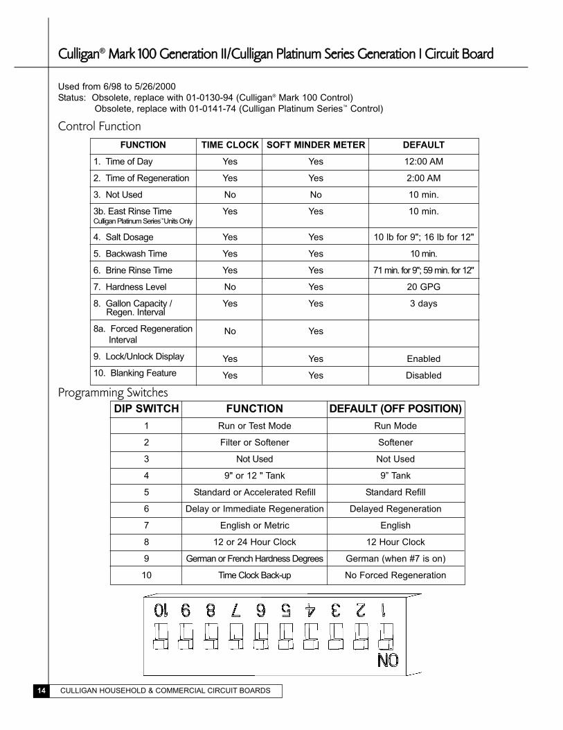
CCuulllliiggaann® MMaarrkk 110000 GGeenneerraattiioonn IIII//CCuulllliiggaann PPllaattiinnuumm SSeerriieess GGeenneerraattiioonn II CCiirrccuuiitt BBooaarrdd
Used from 6/98 to 5/26/2000
Status: Obsolete, replace with 01-0130-94 (Culligan® Mark 100 Control)
Obsolete, replace with 01-0141-74 (Culligan Platinum Series™ Control)
Control Function
Programming Switches
CULLIGAN HOUSEHOLD & COMMERCIAL CIRCUIT BOARDS14
DIP SWITCH
1
2
3
4
5
6
7
8
9
10
FUNCTION
Run or Test Mode
Filter or Softener
Not Used
9" or 12 " Tank
Standard or Accelerated Refill
Delay or Immediate Regeneration
English or Metric
12 or 24 Hour Clock
German or French Hardness Degrees
Time Clock Back-up
DEFAULT (OFF POSITION)
Run Mode
Softener
Not Used
9” Tank
Standard Refill
Delayed Regeneration
English
12 Hour Clock
German (when #7 is on)
No Forced Regeneration
FUNCTION
1. Time of Day
2. Time of Regeneration
3. Not Used
3b. East Rinse TimeCulligan Platinum Series™Units Only
4. Salt Dosage
5. Backwash Time
6. Brine Rinse Time
7. Hardness Level
8. Gallon Capacity /Regen. Interval
8a. Forced Regeneration
Interval
9. Lock/Unlock Display
10. Blanking Feature
TIME CLOCK
Yes
Yes
No
Yes
Yes
Yes
Yes
No
Yes
No
Yes
Yes
SOFT MINDER METER
Yes
Yes
No
Yes
Yes
Yes
Yes
Yes
Yes
Yes
Yes
Yes
DEFAULT
12:00 AM
2:00 AM
10 min.
10 min.
10 lb for 9"; 16 lb for 12"
10 min.
71 min. for 9"; 59 min. for 12"
20 GPG
3 days
Enabled
Disabled

CULLIGAN HOUSEHOLD & COMMERCIAL CIRCUIT BOARDS 15
CCoonnnneeccttiioonnss
FIG. 3 - Circuit Board Display
The display will initially power up flashing "8888". After 1 minute the motor will energize and cycle the control,
without stopping, to the home position. This is required to ensure that the control is in the home position.
The timer uses four buttons:
1. STATUS: Advance timer through display options.
2. UP ARROW: Increase the setting.
3. DOWN ARROW: Decrease the setting.
4. REGEN.: Initiate a manual regeneration.
Programming
CULLIGAN HOUSEHOLD & COMMERCIAL CIRCUIT BOARDS16
Press � to increase or
� to decrease
Press � to increase or
� to decrease
Press � to increase or
� to decrease
Press � to increase or
� to decrease
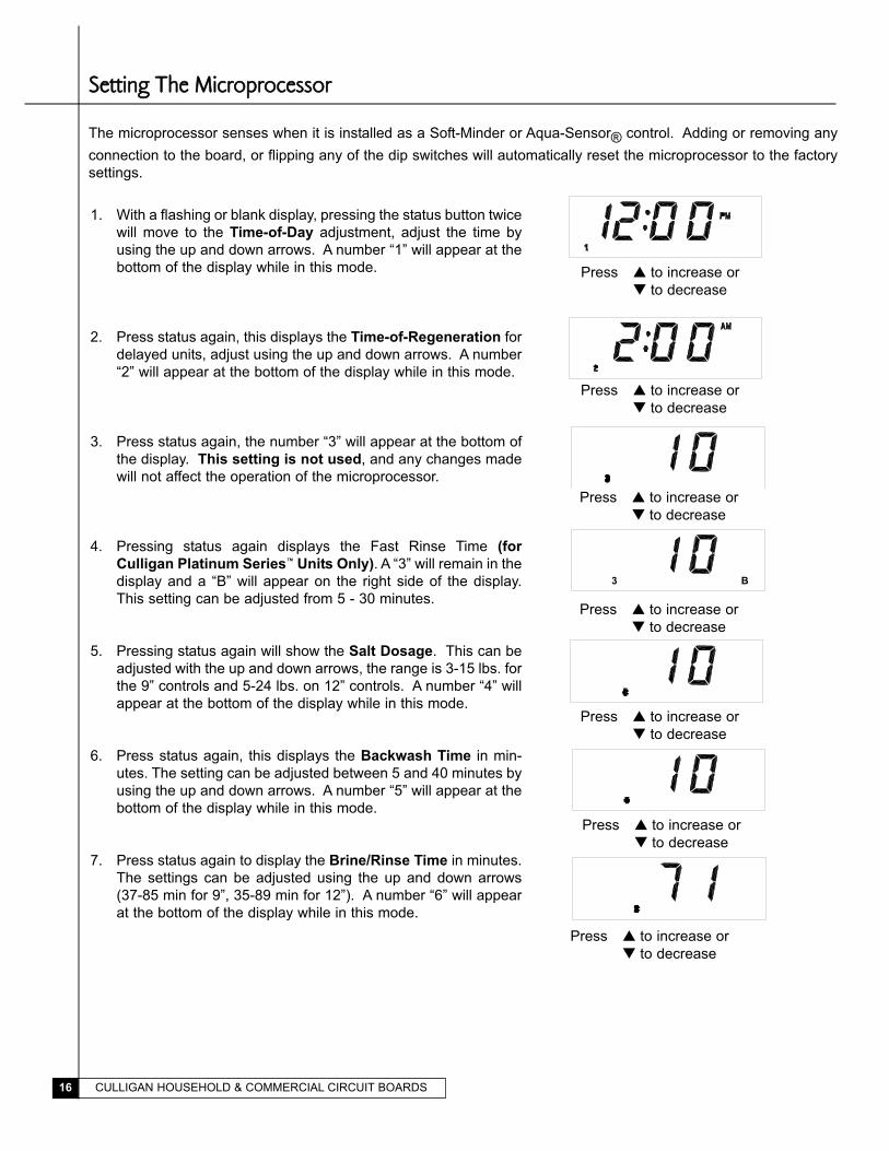
1. With a flashing or blank display, pressing the status button twice
will move to the Time-of-Day adjustment, adjust the time by
using the up and down arrows. A number “1” will appear at the
bottom of the display while in this mode.
2. Press status again, this displays the Time-of-Regeneration for
delayed units, adjust using the up and down arrows. A number
“2” will appear at the bottom of the display while in this mode.
3. Press status again, the number “3” will appear at the bottom of
the display. This setting is not used, and any changes made
will not affect the operation of the microprocessor.
4. Pressing status again displays the Fast Rinse Time (for
Culligan Platinum Series™ Units Only). A “3” will remain in the
display and a “B” will appear on the right side of the display.
This setting can be adjusted from 5 - 30 minutes.
5. Pressing status again will show the Salt Dosage. This can be
adjusted with the up and down arrows, the range is 3-15 lbs. for
the 9” controls and 5-24 lbs. on 12” controls. A number “4” will
appear at the bottom of the display while in this mode.
6. Press status again, this displays the Backwash Time in min-
utes. The setting can be adjusted between 5 and 40 minutes by
using the up and down arrows. A number “5” will appear at the
bottom of the display while in this mode.
7. Press status again to display the Brine/Rinse Time in minutes.
The settings can be adjusted using the up and down arrows
(37-85 min for 9”, 35-89 min for 12”). A number “6” will appear
at the bottom of the display while in this mode.
Press � to increase or
� to decrease
SSeettttiinngg TThhee MMiiccrroopprroocceessssoorr
The microprocessor senses when it is installed as a Soft-Minder or Aqua-Sensor® control. Adding or removing any
connection to the board, or flipping any of the dip switches will automatically reset the microprocessor to the factory
settings.
Press � to increase or
� to decrease
Press � to increase or
� to decrease
3 B
CULLIGAN HOUSEHOLD & COMMERCIAL CIRCUIT BOARDS 17
Press � to increase or
� to decrease
Press � simultaneously
�
Press � to change
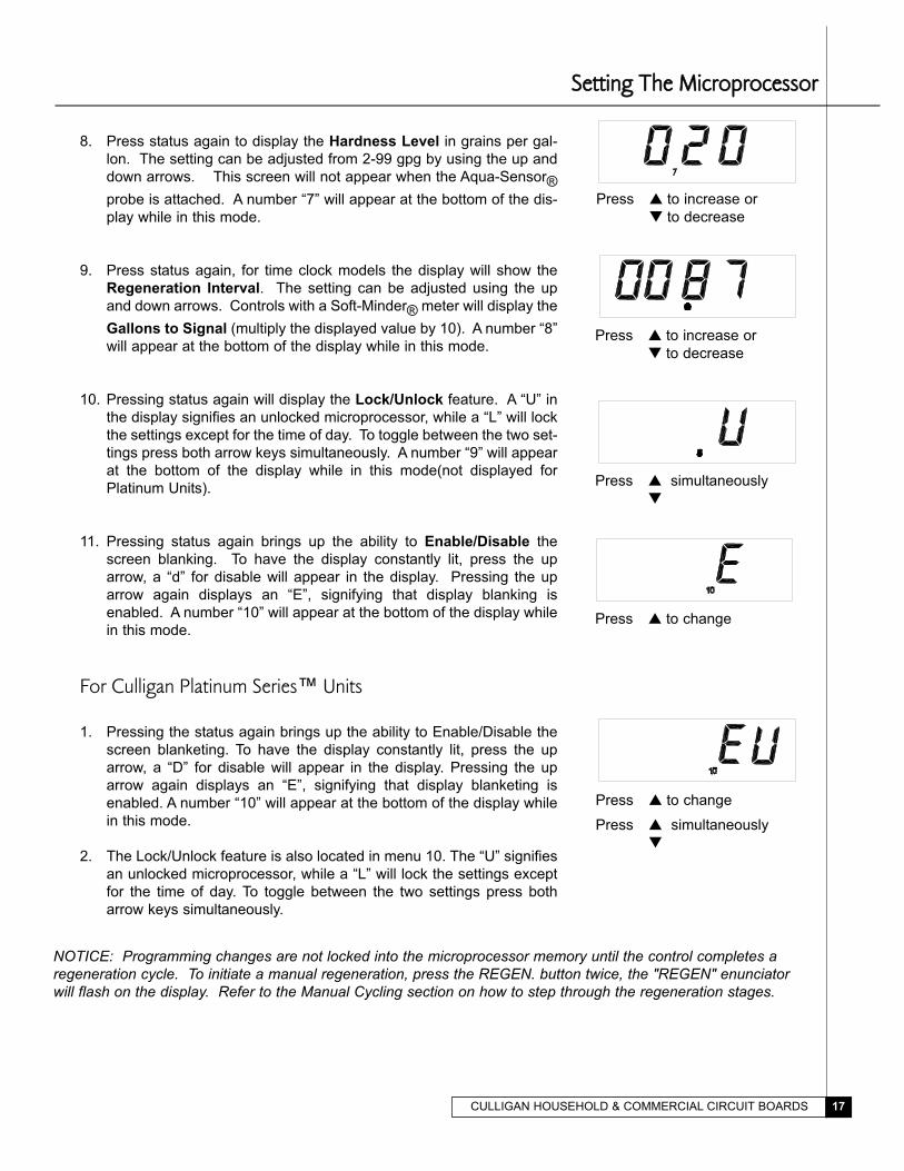
8. Press status again to display the Hardness Level in grains per gal-
lon. The setting can be adjusted from 2-99 gpg by using the up and
down arrows. This screen will not appear when the Aqua-Sensor®
probe is attached. A number “7” will appear at the bottom of the dis-
play while in this mode.
9. Press status again, for time clock models the display will show the
Regeneration Interval. The setting can be adjusted using the up
and down arrows. Controls with a Soft-Minder® meter will display the
Gallons to Signal (multiply the displayed value by 10). A number “8”
will appear at the bottom of the display while in this mode.
10. Pressing status again will display the Lock/Unlock feature. A “U” in
the display signifies an unlocked microprocessor, while a “L” will lock
the settings except for the time of day. To toggle between the two set-
tings press both arrow keys simultaneously. A number “9” will appear
at the bottom of the display while in this mode(not displayed for
Platinum Units).
11. Pressing status again brings up the ability to Enable/Disable the
screen blanking. To have the display constantly lit, press the up
arrow, a “d” for disable will appear in the display. Pressing the up
arrow again displays an “E”, signifying that display blanking is
enabled. A number “10” will appear at the bottom of the display while
in this mode.
For Culligan Platinum Series™ Units
1. Pressing the status again brings up the ability to Enable/Disable the
screen blanketing. To have the display constantly lit, press the up
arrow, a “D” for disable will appear in the display. Pressing the up
arrow again displays an “E”, signifying that display blanketing is
enabled. A number “10” will appear at the bottom of the display while
in this mode.
2. The Lock/Unlock feature is also located in menu 10. The “U” signifies
an unlocked microprocessor, while a “L” will lock the settings except
for the time of day. To toggle between the two settings press both
arrow keys simultaneously.
Press � to increase or
� to decrease
NOTICE: Programming changes are not locked into the microprocessor memory until the control completes aregeneration cycle. To initiate a manual regeneration, press the REGEN. button twice, the "REGEN" enunciatorwill flash on the display. Refer to the Manual Cycling section on how to step through the regeneration stages.
Press � simultaneously
�
Press � to change
SSeettttiinngg TThhee MMiiccrroopprroocceessssoorr
CULLIGAN HOUSEHOLD & COMMERCIAL CIRCUIT BOARDS18
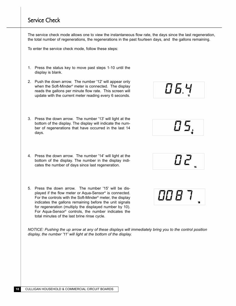
The service check mode allows one to view the instantaneous flow rate, the days since the last regeneration,
the total number of regenerations, the regenerations in the past fourteen days, and the gallons remaining.
To enter the service check mode, follow these steps:
SSeerrvviiccee CChheecckk
1. Press the status key to move past steps 1-10 until the
display is blank.
2. Push the down arrow. The number '12' will appear only
when the Soft-Minder® meter is connected. The display
reads the gallons per minute flow rate. This screen will
update with the current meter reading every 6 seconds.
3. Press the down arrow. The number '13' will light at the
bottom of the display. The display will indicate the num-
ber of regenerations that have occurred in the last 14
days.
4. Press the down arrow. The number '14' will light at the
bottom of the display. The number in the display indi-
cates the number of days since last regeneration.
5. Press the down arrow. The number '15' will be dis-
played if the flow meter or Aqua-Sensor® is connected.
For the controls with the Soft-Minder® meter, the display
indicates the gallons remaining before the unit signals
for regeneration (multiply the displayed number by 10).
For Aqua-Sensor® controls, the number indicates the
total minutes of the last brine rinse cycle.
NOTICE: Pushing the up arrow at any of these displays will immediately bring you to the control positiondisplay, the number '11' will light at the bottom of the display.
CULLIGAN HOUSEHOLD & COMMERCIAL CIRCUIT BOARDS 19
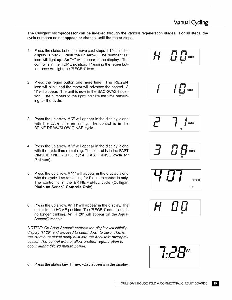
MMaannuuaall CCyycclliinngg
The Culligan® microprocessor can be indexed through the various regeneration stages. For all steps, the
cycle numbers do not appear, or change, until the motor stops.
1. Press the status button to move past steps 1-10 until the
display is blank. Push the up arrow. The number “11”
icon will light up. An "H" will appear in the display. The
control is in the HOME position. Pressing the regen but-
ton once will light the 'REGEN' icon.
2. Press the regen button one more time. The 'REGEN'
icon will blink, and the motor will advance the control. A
'1' will appear. The unit is now in the BACKWASH posi-
tion. The numbers to the right indicate the time remain-
ing for the cycle.
3. Press the up arrow. A '2' will appear in the display, along
with the cycle time remaining. The control is in the
BRINE DRAW/SLOW RINSE cycle.
4. Press the up arrow. A '3' will appear in the display, along
with the cycle time remaining. The control is in the FAST
RINSE/BRINE REFILL cycle (FAST RINSE cycle for
Platinum).
5. Press the up arrow. A “4” will appear in the display along
with the cycle time remaining for Platinum control is only.
The control is in the BRINE REFILL cycle (Culligan
Platinum Series™ Controls Only).
6. Press the up arrow. An 'H' will appear in the display. The
unit is in the HOME position. The 'REGEN' enunciator is
no longer blinking. An 'H 20' will appear on the Aqua-
Sensor® models.
NOTICE: On Aqua-Sensor® controls the display will initiallydisplay "H 20" and proceed to count down to zero. This isthe 20 minute signal delay built into the Accusoft® micropro-cessor. The control will not allow another regeneration tooccur during this 20 minute period.
6. Press the status key. Time-of-Day appears in the display.
7:28PM
4 07 REGEN
11
CULLIGAN HOUSEHOLD & COMMERCIAL CIRCUIT BOARDS20
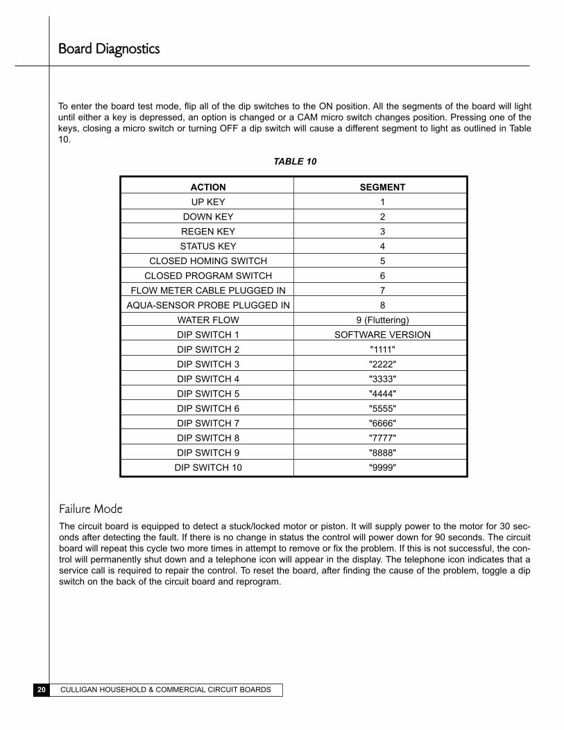
BBooaarrdd DDiiaaggnnoossttiiccss
To enter the board test mode, flip all of the dip switches to the ON position. All the segments of the board will light
until either a key is depressed, an option is changed or a CAM micro switch changes position. Pressing one of the
keys, closing a micro switch or turning OFF a dip switch will cause a different segment to light as outlined in Table
10.
TABLE 10
ACTION SEGMENT
UP KEY 1
DOWN KEY 2
REGEN KEY 3
STATUS KEY 4
CLOSED HOMING SWITCH 5
CLOSED PROGRAM SWITCH 6
FLOW METER CABLE PLUGGED IN 7
AQUA-SENSOR PROBE PLUGGED IN 8
WATER FLOW 9 (Fluttering)
DIP SWITCH 1 SOFTWARE VERSION
DIP SWITCH 2 "1111"
DIP SWITCH 3 "2222"
DIP SWITCH 4 "3333"
DIP SWITCH 5 "4444"
DIP SWITCH 6 "5555"
DIP SWITCH 7 "6666"
DIP SWITCH 8 "7777"
DIP SWITCH 9 "8888"
DIP SWITCH 10 "9999"
Failure ModeThe circuit board is equipped to detect a stuck/locked motor or piston. It will supply power to the motor for 30 sec-
onds after detecting the fault. If there is no change in status the control will power down for 90 seconds. The circuit
board will repeat this cycle two more times in attempt to remove or fix the problem. If this is not successful, the con-
trol will permanently shut down and a telephone icon will appear in the display. The telephone icon indicates that a
service call is required to repair the control. To reset the board, after finding the cause of the problem, toggle a dip
switch on the back of the circuit board and reprogram.
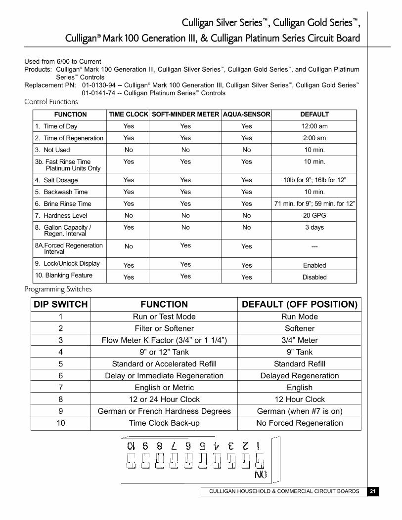
CCuulllliiggaann SSiillvveerr SSeerriieess™,, CCuulllliiggaann GGoolldd SSeerriieess™,,
CCuulllliiggaann® MMaarrkk 110000 GGeenneerraattiioonn IIIIII,, && CCuulllliiggaann PPllaattiinnuumm SSeerriieess CCiirrccuuiitt BBooaarrdd
Used from 6/00 to Current
Products: Culligan® Mark 100 Generation III, Culligan Silver Series™, Culligan Gold Series™, and Culligan Platinum
Series™ Controls
Replacement PN: 01-0130-94 -- Culligan® Mark 100 Generation III, Culligan Silver Series™, Culligan Gold Series™
01-0141-74 -- Culligan Platinum Series™ Controls
Control Functions
Programming Switches
CULLIGAN HOUSEHOLD & COMMERCIAL CIRCUIT BOARDS 21
FUNCTION
1. Time of Day
2. Time of Regeneration
3. Not Used
3b. Fast Rinse Time Platinum Units Only
4. Salt Dosage
5. Backwash Time
6. Brine Rinse Time
7. Hardness Level
8. Gallon Capacity /Regen. Interval
8A.Forced RegenerationInterval
9. Lock/Unlock Display
10. Blanking Feature
TIME CLOCK
Yes
Yes
No
Yes
Yes
Yes
Yes
No
Yes
No
Yes
Yes
SOFT-MINDER METER
Yes
Yes
No
Yes
Yes
Yes
Yes
No
No
Yes
Yes
Yes
AQUA-SENSOR
Yes
Yes
No
Yes
Yes
Yes
Yes
No
No
Yes
Yes
Yes
DEFAULT
12:00 am
2:00 am
10 min.
10 min.
10lb for 9”; 16lb for 12”
10 min.
71 min. for 9”; 59 min. for 12”
20 GPG
3 days
---
Enabled
Disabled
DIP SWITCH
1
2
3
4
5
6
7
8
9
10
FUNCTION
Run or Test Mode
Filter or Softener
Flow Meter K Factor (3/4” or 1 1/4”)
9” or 12” Tank
Standard or Accelerated Refill
Delay or Immediate Regeneration
English or Metric
12 or 24 Hour Clock
German or French Hardness Degrees
Time Clock Back-up
DEFAULT (OFF POSITION)
Run Mode
Softener
3/4” Meter
9” Tank
Standard Refill
Delayed Regeneration
English
12 Hour Clock
German (when #7 is on)
No Forced Regeneration
CULLIGAN HOUSEHOLD & COMMERCIAL CIRCUIT BOARDS22
CCoonnnneeccttiioonnss
Press � to increase or
� to decrease
Press � to increase or
� to decrease
Press � to increase or
� to decrease
FIG. 3 - Circuit Board Display
The display will initially power up flashing "12:00 PM". After 1 minute the motor will energize and cycle the control,
without stopping, to the home position. This is required to ensure that the control is in the home position.
Programming
The timer uses four buttons:
1. STATUS: Advance timer through display options.
2. UP ARROW: Increase the setting.
3. DOWN ARROW: Decrease the setting.
4. REGEN.: Initiate a manual regeneration.
SETTING THE MICROPROCESSOR
The microprocessor senses when it is installed as a Soft-Minder® or Aqua-Sensor® control. Adding or remov-
ing any connection to the board, or flipping any of the dip switches will automatically reset the microproces-
sor to the factory settings.
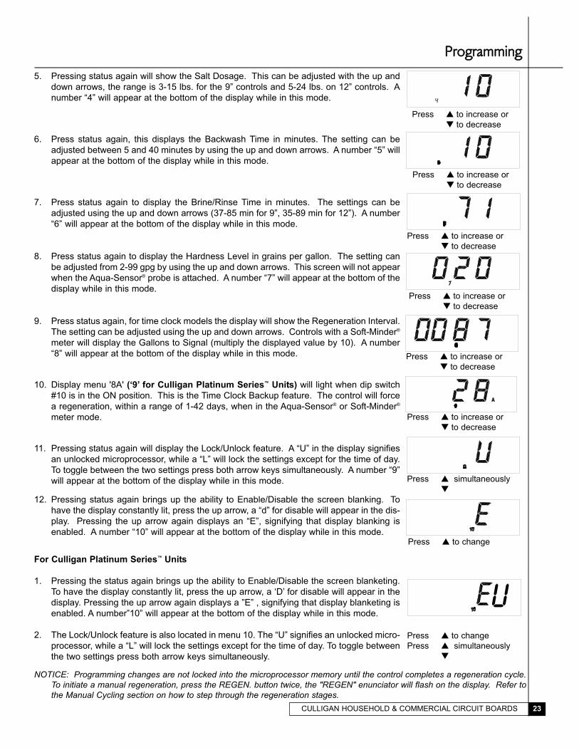
1. With a flashing or blank display, pressing the status button twice will
move to the Time-of-Day adjustment, adjust the time by using the up
and down arrows. A number “1” will appear at the bottom of the dis-
play while in this mode.
2. Press status again, this displays the Time-of-Regeneration for
delayed units, adjust using the up and down arrows. A number “2”
will appear at the bottom of the display while in this mode.
3. Press status again, the number “3” will appear at the bottom of the
display. This setting is not used, and any changes made will not
affect the operation of the microprocessor.
4. Pressing status again will show the Fast Rinse Time (for Culligan
Platinum Series™ Units Only). A “3” will remain in the display and a
“B” will appear on the right side of the display. This setting can be
adjusted from 5-30 minutes.Press � to increase or
� to decrease
AB
CULLIGAN HOUSEHOLD & COMMERCIAL CIRCUIT BOARDS 23
Press � to increase or
� to decrease
5. Pressing status again will show the Salt Dosage. This can be adjusted with the up and
down arrows, the range is 3-15 lbs. for the 9” controls and 5-24 lbs. on 12” controls. A
number “4” will appear at the bottom of the display while in this mode.
6. Press status again, this displays the Backwash Time in minutes. The setting can be
adjusted between 5 and 40 minutes by using the up and down arrows. A number “5” will
appear at the bottom of the display while in this mode.
7. Press status again to display the Brine/Rinse Time in minutes. The settings can be
adjusted using the up and down arrows (37-85 min for 9”, 35-89 min for 12”). A number
“6” will appear at the bottom of the display while in this mode.
8. Press status again to display the Hardness Level in grains per gallon. The setting can
be adjusted from 2-99 gpg by using the up and down arrows. This screen will not appear
when the Aqua-Sensor® probe is attached. A number “7” will appear at the bottom of the
display while in this mode.
9. Press status again, for time clock models the display will show the Regeneration Interval.
The setting can be adjusted using the up and down arrows. Controls with a Soft-Minder®
meter will display the Gallons to Signal (multiply the displayed value by 10). A number
“8” will appear at the bottom of the display while in this mode.
10. Display menu '8A' (‘9’ for Culligan Platinum Series™ Units) will light when dip switch
#10 is in the ON position. This is the Time Clock Backup feature. The control will force
a regeneration, within a range of 1-42 days, when in the Aqua-Sensor® or Soft-Minder®
meter mode.
11. Pressing status again will display the Lock/Unlock feature. A “U” in the display signifies
an unlocked microprocessor, while a “L” will lock the settings except for the time of day.
To toggle between the two settings press both arrow keys simultaneously. A number “9”
will appear at the bottom of the display while in this mode.
12. Pressing status again brings up the ability to Enable/Disable the screen blanking. To
have the display constantly lit, press the up arrow, a “d” for disable will appear in the dis-
play. Pressing the up arrow again displays an “E”, signifying that display blanking is
enabled. A number “10” will appear at the bottom of the display while in this mode.
For Culligan Platinum Series™ Units
1. Pressing the status again brings up the ability to Enable/Disable the screen blanketing.
To have the display constantly lit, press the up arrow, a ‘D’ for disable will appear in the
display. Pressing the up arrow again displays a ”E” , signifying that display blanketing is
enabled. A number”10” will appear at the bottom of the display while in this mode.
2. The Lock/Unlock feature is also located in menu 10. The “U” signifies an unlocked micro-
processor, while a “L” will lock the settings except for the time of day. To toggle between
the two settings press both arrow keys simultaneously.
Press � to increase or
� to decrease
4
Press � to increase or
� to decrease
Press � to increase or
� to decrease
Press � to increase or
� to decrease
Press � to increase or
� to decrease
Press � simultaneously
�
Press � to change
Press � simultaneously
�
Press � to change
U
NOTICE: Programming changes are not locked into the microprocessor memory until the control completes a regeneration cycle.To initiate a manual regeneration, press the REGEN. button twice, the "REGEN" enunciator will flash on the display. Refer tothe Manual Cycling section on how to step through the regeneration stages.
PPrrooggrraammmmiinngg

CULLIGAN HOUSEHOLD & COMMERCIAL CIRCUIT BOARDS24
MMaannuuaall CCyycclliinngg
The Culligan® microprocessor can be indexed through the various regeneration stages. For all steps, the cycle
numbers do not appear, or change, until the motor stops.
1. Press the status button to move past steps 1-10 until the display is
blank. Push the up arrow. The number “11” icon will light up. An "H"
will appear in the display. The control is in the HOME position.
Pressing the regen button once will light the 'REGEN' icon.
2. Press the regen button one more time. The 'REGEN' icon will blink,
and the motor will advance the control. A '1' will appear. The unit is
now in the BACKWASH position. The numbers to the right indicate the
time remaining for the cycle.
3. Press the up arrow. A '2' will appear in the display, along with the cycle
time remaining. The control is in the BRINE DRAW/SLOW RINSE
cycle.
4. Press the up arrow. A '3' will appear in the display, along with the cycle
time remaining. The control is in the FAST RINSE/BRINE REFILL
cycle.
5. Press the up arrow. A “4” will appear in the display along with the cycle
time remaining for Platinum control only. The control is in the BRINE
REFILL cycle (Platinum Controls Only).
6. Press the up arrow. An 'H' will appear in the display. The unit is in the
HOME position. The 'REGEN' enunciator is no longer blinking. An 'H
20' will appear on the Aqua-Sensor® models.
NOTICE: On Aqua-Sensor® controls the display will initially display "H 20"and proceed to count down to zero. This is the 20 minute signal delaybuilt into the Accusoft® microprocessor. The control will not allow anotherregeneration to occur during this 20 minute period.
7. Press the status key. Time-of-Day appears in the display. 7:28 PM
4
CULLIGAN HOUSEHOLD & COMMERCIAL CIRCUIT BOARDS 25
The service check mode allows one to view the instantaneous flow rate, the days since the last regeneration,
the total number of regenerations, the regenerations in the past fourteen days, and the gallons remaining.
To enter the service check mode, follow these steps:
SSeerrvviiccee CChheecckk
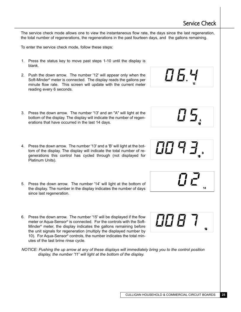
1. Press the status key to move past steps 1-10 until the display is
blank.
2. Push the down arrow. The number '12' will appear only when the
Soft-Minder® meter is connected. The display reads the gallons per
minute flow rate. This screen will update with the current meter
reading every 6 seconds.
3. Press the down arrow. The number '13' and an "A" will light at the
bottom of the display. The display will indicate the number of regen-
erations that have occurred in the last 14 days.
4. Press the down arrow. The number '13' and a 'B' will light at the bot-
tom of the display. The display will indicate the total number of re-
generations this control has cycled through (not displayed for
Platinum Units).
5. Press the down arrow. The number '14' will light at the bottom of
the display. The number in the display indicates the number of days
since last regeneration.
6. Press the down arrow. The number '15' will be displayed if the flow
meter or Aqua-Sensor® is connected. For the controls with the Soft-
Minder® meter, the display indicates the gallons remaining before
the unit signals for regeneration (multiply the displayed number by
10). For Aqua-Sensor® controls, the number indicates the total min-
utes of the last brine rinse cycle.
NOTICE: Pushing the up arrow at any of these displays will immediately bring you to the control position display, the number '11' will light at the bottom of the display.
0
CULLIGAN HOUSEHOLD & COMMERCIAL CIRCUIT BOARDS26
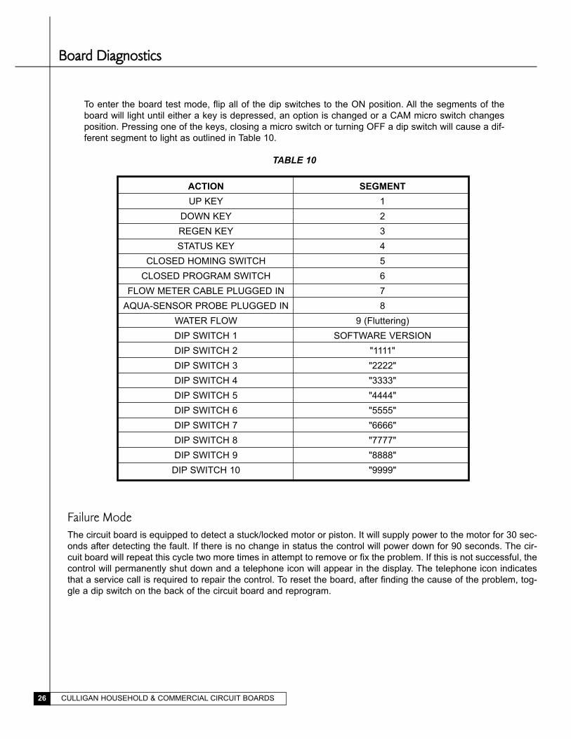
To enter the board test mode, flip all of the dip switches to the ON position. All the segments of the
board will light until either a key is depressed, an option is changed or a CAM micro switch changes
position. Pressing one of the keys, closing a micro switch or turning OFF a dip switch will cause a dif-
ferent segment to light as outlined in Table 10.
TABLE 10
ACTION SEGMENT
UP KEY 1
DOWN KEY 2
REGEN KEY 3
STATUS KEY 4
CLOSED HOMING SWITCH 5
CLOSED PROGRAM SWITCH 6
FLOW METER CABLE PLUGGED IN 7
AQUA-SENSOR PROBE PLUGGED IN 8
WATER FLOW 9 (Fluttering)
DIP SWITCH 1 SOFTWARE VERSION
DIP SWITCH 2 "1111"
DIP SWITCH 3 "2222"
DIP SWITCH 4 "3333"
DIP SWITCH 5 "4444"
DIP SWITCH 6 "5555"
DIP SWITCH 7 "6666"
DIP SWITCH 8 "7777"
DIP SWITCH 9 "8888"
DIP SWITCH 10 "9999"
BBooaarrdd DDiiaaggnnoossttiiccss
Failure ModeThe circuit board is equipped to detect a stuck/locked motor or piston. It will supply power to the motor for 30 sec-
onds after detecting the fault. If there is no change in status the control will power down for 90 seconds. The cir-
cuit board will repeat this cycle two more times in attempt to remove or fix the problem. If this is not successful, the
control will permanently shut down and a telephone icon will appear in the display. The telephone icon indicates
that a service call is required to repair the control. To reset the board, after finding the cause of the problem, tog-
gle a dip switch on the back of the circuit board and reprogram.

CULLIGAN HOUSEHOLD & COMMERCIAL CIRCUIT BOARDS 27
Converting the Culligan Mark 100 Generation I Circuit Board to a Generation III Circuit BoardFamiliarize yourself with the replacement procedures and component parts before attempting any repair.
WARNING! DISCONNECT ALL ELECTRICAL POWER TO THE UNIT BEFORE SERVICING.
INSTALLATION1. Remove the timer cover by twisting the four, quarter turn Phillips screws.
2. Remove the power, microswitch and motor leads from the board. Remove the motor leads from the motor.
WARNING! TO PREVENT DAMAGE TO THE LEADS, PULL THE LEADS BY GRIPPING THE
CONNECTING TERMINALS ONLY.
3. Remove the screws holding the board to the case (Fig.1).
4. Mount the transformer to the backplate – see Fig. 2 for transformer location. Two 11/64" holes need to be drilled
where the screws are to be inserted in to the backplate (the screws provided are thread cutting screws).
5. Mount the terminal strip to the backplate – see Fig. 2 for terminal strip location. A 1/8" hole needs to be drilled
where the screw is to be inserted in to the backplate (the screw provided is a thread cutting screw).
6. Cut the white and black wires from the power cord that is attached to the seven-pin connector (cut the wires as close
to the connector as possible). Cut the green wire from the connector and remove it from the grounding screw.
7. Connect the new motor wire harness to the motor.
8. Refer to the wiring schematic for connecting the power cord wires to the terminal strip, connecting the
transformer wires to the terminal strip and motor leads to the terminal strip.
9. Remove the new circuit board from its protective wrap and install the circuit board.
CAUTION: Do not touch any surface of the circuit board.
Electrical static discharges can damage the board. Handle the board by the edges only.
10. Connect the cam wire harness, motor wire harness and transformer wire harness to the circuit board.
Reconnect the Soft-Minder™ meter cable or Aqua-Sensor® cable if so equipped.
CAUTION: The wire harnesses must be connected to the circuit board properly.
11. Set the dip switches for the proper application, plug in the control and reprogram the softener. Refer to the
Culligan Silver Series™ or Culligan Gold Series™ installation and operation manual for dip switch settings and
programming instructions. Manually cycle the control to confirm the circuit board as been installed correctly.
IInnssttaallllaattiioonn IInnssttrruuccttiioonnss
Fig. 1
Fig. 2
CULLIGAN HOUSEHOLD & COMMERCIAL CIRCUIT BOARDS28
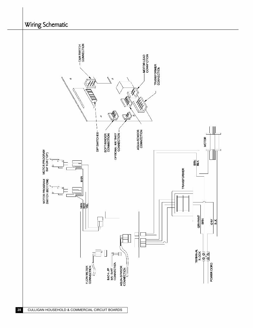
WWiirriinngg SScchheemmaattiicc
CULLIGAN HOUSEHOLD & COMMERCIAL CIRCUIT BOARDS 29
CCuulllliiggaann® AAqquuaa--SSeennssoorr® SSeennssiinngg DDeevviiccee TTrroouubblleesshhoooottiinnggThe following procedure will help you diagnose problems in units equipped with Aqua-Sensor sensing device.
Because many “sensor problems” are actually regeneration problems, it contains a combination of sensor diagnos-
tics and routine control valve and brine system checks. Refer to the Troubleshooting Flow chart on page 3 for the
recommended sequence.
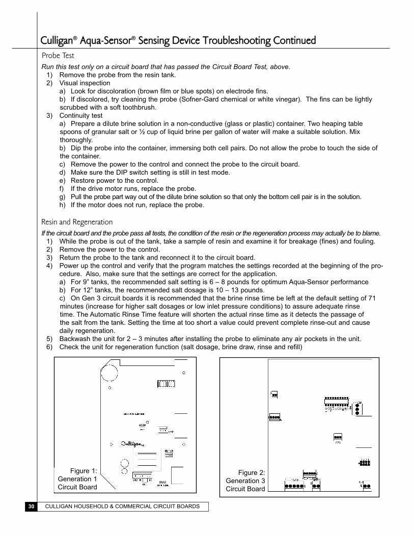
Circuit Board Test1) Identify the circuit board generation (See Fig. 1 for Generation 1, Fig. 2 for Generation 3. There should be no
Generation 2 boards in Aqua-Sensor service)
a) 7 DIP switches & 3 Aqua-Sensor pins – Gen. 1
b) 10 DIP switches & 5 Aqua-Sensor pins – Gen. 3
2) Record program and DIP switch settings before beginning this procedure.
a) For Generation 3 boards determine the slow rinse time of the last regeneration cycle by going to step 15
of the diagnostics menu (See the Service Manual for the control to determine how to get to step 15).
3) Unplug the unit before changing any DIP switch positions.
4) Remove the Aqua-Sensor cable from the board.
5) Move DIP switch(es) to Test Mode.
a) Gen. 1 – DIP switches 1 & 2 ON, all others OFF
b) Gen. 3 – DIP switch 1 ON, all others OFF
Generation 16) Connect Aqua-Sensor Tester (P/N 01007999) to board; the white wire should plug on the right most pin of the
connector as you look at the back of the board. Only three of the sockets of the simulator connector will be
used with the colors of the wires from left to right being black, red and white (Fig. 1).
7) Move toggle to Balanced position
8) Plug the control in (motor should not run).
9) If motor runs, replace the board.
10) Move toggle to the Unbalanced position (motor should run).
11) If motor does not run, replace the board.
12) If board passes both tests, board is good.
13) Unplug the control and advance to the probe test.
Generation 36) Connect Aqua-Sensor Tester (P/N 01007999) to board; wires should be on top of connector with all pins
being connected. The color of the wire on the far left as you look at the back of the board should be white
(Fig. 2).
7) Move toggle to Balanced position.
8) Plug the control in (motor should not run).
9) If motor runs, replace the board.
10) Move toggle to the Unbalanced position (motor should run).
11) If motor does not run, replace the board.
12) If board passes both tests, board is good.
13) Unplug the control and advance to the probe test.
Optional Service TestIf you wish, you can also test the circuit board in the Service mode (DIP switches in the Service, rather than Test, position.
1) Follow Circuit Board Test steps 1 through 4
2) Connect Aqua-Sensor Simulator (P/N 01007999) to the circuit board with the toggle in the Balanced position.
3) Plug in the control.
4) Move the Aqua-Sensor Simulator toggle to the Unbalanced position
a) Gen. 1: The circuit board should display a REGEN signal after a 1-minute delay.
b) Gen. 3: The circuit board should display a REGEN signal after a 6-minute delay.
CCuulllliiggaann® AAqquuaa--SSeennssoorr® SSeennssiinngg DDeevviiccee TTrroouubblleesshhoooottiinngg CCoonnttiinnuueeddProbe TestRun this test only on a circuit board that has passed the Circuit Board Test, above.
1) Remove the probe from the resin tank.
2) Visual inspection
a) Look for discoloration (brown film or blue spots) on electrode fins.
b) If discolored, try cleaning the probe (Sofner-Gard chemical or white vinegar). The fins can be lightly
scrubbed with a soft toothbrush.
3) Continuity test
a) Prepare a dilute brine solution in a non-conductive (glass or plastic) container. Two heaping table
spoons of granular salt or ½ cup of liquid brine per gallon of water will make a suitable solution. Mix
thoroughly.
b) Dip the probe into the container, immersing both cell pairs. Do not allow the probe to touch the side of
the container.
c) Remove the power to the control and connect the probe to the circuit board.
d) Make sure the DIP switch setting is still in test mode.
e) Restore power to the control.
f) If the drive motor runs, replace the probe.
g) Pull the probe part way out of the dilute brine solution so that only the bottom cell pair is in the solution.
h) If the motor does not run, replace the probe.
Resin and RegenerationIf the circuit board and the probe pass all tests, the condition of the resin or the regeneration process may actually be to blame.
1) While the probe is out of the tank, take a sample of resin and examine it for breakage (fines) and fouling.
2) Remove the power to the control.
3) Return the probe to the tank and reconnect it to the circuit board.
4) Power up the control and verify that the program matches the settings recorded at the beginning of the pro-
cedure. Also, make sure that the settings are correct for the application.
a) For 9” tanks, the recommended salt setting is 6 – 8 pounds for optimum Aqua-Sensor performance
b) For 12” tanks, the recommended salt dosage is 10 – 13 pounds.
c) On Gen 3 circuit boards it is recommended that the brine rinse time be left at the default setting of 71
minutes (increase for higher salt dosages or low inlet pressure conditions) to assure adequate rinse
time. The Automatic Rinse Time feature will shorten the actual rinse time as it detects the passage of
the salt from the tank. Setting the time at too short a value could prevent complete rinse-out and cause
daily regeneration.
5) Backwash the unit for 2 – 3 minutes after installing the probe to eliminate any air pockets in the unit.
6) Check the unit for regeneration function (salt dosage, brine draw, rinse and refill)
CULLIGAN HOUSEHOLD & COMMERCIAL CIRCUIT BOARDS30
Figure 1:
Generation 1
Circuit Board
Figure 2:
Generation 3
Circuit Board
CULLIGAN HOUSEHOLD & COMMERCIAL CIRCUIT BOARDS 31
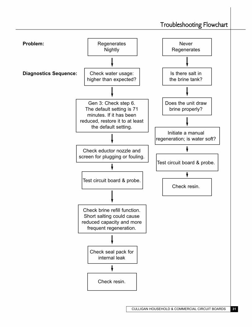
TTrroouubblleesshhoooottiinngg FFlloowwcchhaarrtt
Problem: Regenerates Never
Nightly Regenerates
Diagnostics Sequence: Check water usage: Is there salt in
higher than expected? the brine tank?
Gen 3: Check step 6. Does the unit draw
The default setting is 71 brine properly?
minutes. If it has been
reduced, restore it to at least
the default setting.
Initiate a manual
regeneration; is water soft?
Check eductor nozzle and
screen for plugging or fouling.
Test circuit board & probe.
Test circuit board & probe.
Check resin.
Check brine refill function.
Short salting could cause
reduced capacity and more
frequent regeneration.
Check seal pack for
internal leak
Check resin.

CULLIGAN HOUSEHOLD & COMMERCIAL CIRCUIT BOARDS32
CCuulllliiggaann® MMaarrkk 1100 aanndd EEssttaattee 22MM GGeenneerraattiioonn II CCiirrccuuiitt BBooaarrdd
Used from 11/95 to 2/98
Replacement PN: 01-0063-22 - 110 volt
01-0063-23 - 24 volt
Status: Obsolete, replace with 01-0129-63 - 110 volt
01-0148-93 - 24 volt
PROGRAMMING SWITCHES
CAPACITY SWITCH SETTINGS
GALLONS SW 2 SW 3 SW 4
300 ON ON ON
600 ON ON OFF
900 ON OFF ON
1200 ON OFF OFF
1600 OFF ON ON
2000 OFF ON OFF
2500 OFF OFF ON
3000 OFF OFF OFF
SW 1 RUN TEST
ON OFF
There is one pilot light located on the circuit board.
•The amber pilot light is a latching indicator, when the preset gallons count has passed. The light
will illuminate indicating that the unit will regenerate that night.
CULLIGAN HOUSEHOLD & COMMERCIAL CIRCUIT BOARDS 33
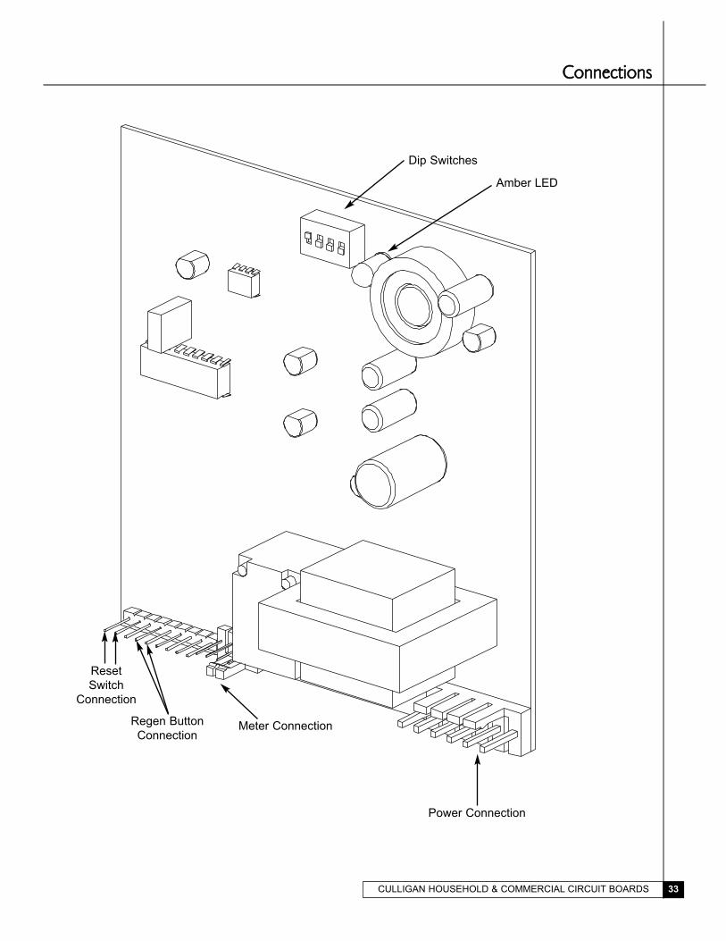
CCoonnnneeccttiioonnss
Dip Switches
Amber LED
Power Connection
Meter ConnectionRegen Button
Connection
Reset
Switch
Connection
CULLIGAN HOUSEHOLD & COMMERCIAL CIRCUIT BOARDS34
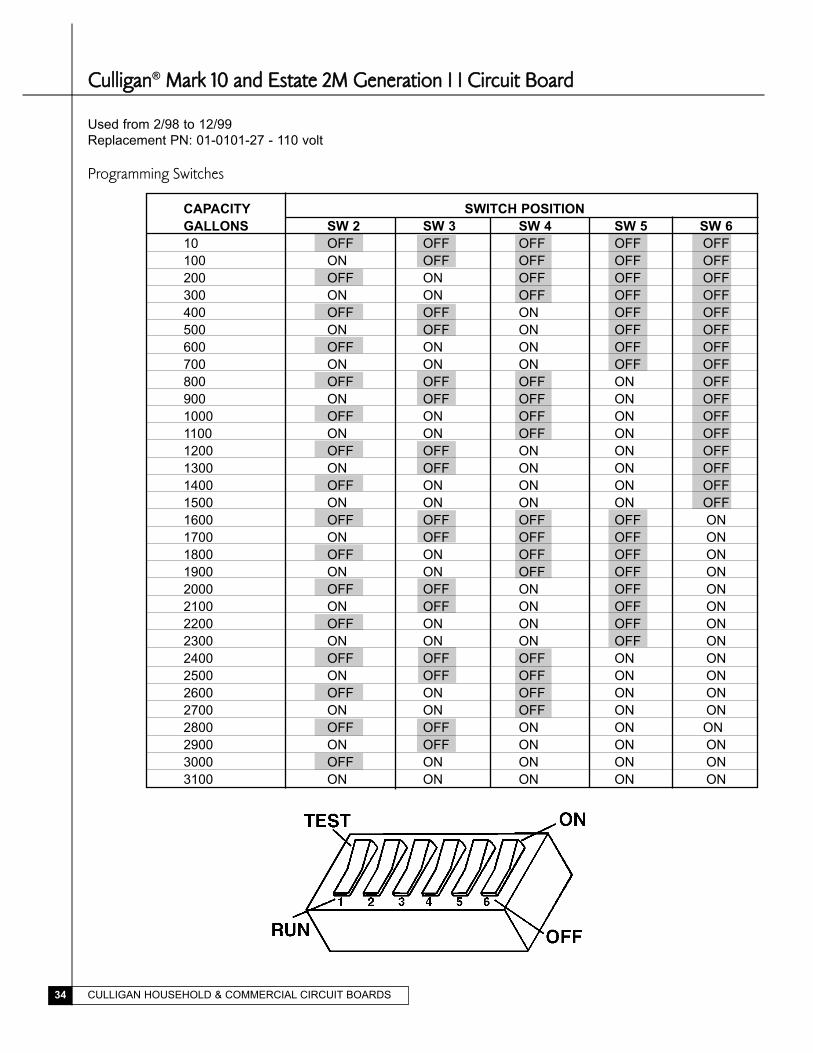
CCuulllliiggaann® MMaarrkk 1100 aanndd EEssttaattee 22MM GGeenneerraattiioonn II II CCiirrccuuiitt BBooaarrdd
Used from 2/98 to 12/99
Replacement PN: 01-0101-27 - 110 volt
Programming Switches
CAPACITY SWITCH POSITION
GALLONS SW 2 SW 3 SW 4 SW 5 SW 6
10 OFF OFF OFF OFF OFF
100 ON OFF OFF OFF OFF
200 OFF ON OFF OFF OFF
300 ON ON OFF OFF OFF
400 OFF OFF ON OFF OFF
500 ON OFF ON OFF OFF
600 OFF ON ON OFF OFF
700 ON ON ON OFF OFF
800 OFF OFF OFF ON OFF
900 ON OFF OFF ON OFF
1000 OFF ON OFF ON OFF
1100 ON ON OFF ON OFF
1200 OFF OFF ON ON OFF
1300 ON OFF ON ON OFF
1400 OFF ON ON ON OFF
1500 ON ON ON ON OFF
1600 OFF OFF OFF OFF ON
1700 ON OFF OFF OFF ON
1800 OFF ON OFF OFF ON
1900 ON ON OFF OFF ON
2000 OFF OFF ON OFF ON
2100 ON OFF ON OFF ON
2200 OFF ON ON OFF ON
2300 ON ON ON OFF ON
2400 OFF OFF OFF ON ON
2500 ON OFF OFF ON ON
2600 OFF ON OFF ON ON
2700 ON ON OFF ON ON
2800 OFF OFF ON ON ON
2900 ON OFF ON ON ON
3000 OFF ON ON ON ON
3100 ON ON ON ON ON
CULLIGAN HOUSEHOLD & COMMERCIAL CIRCUIT BOARDS 35
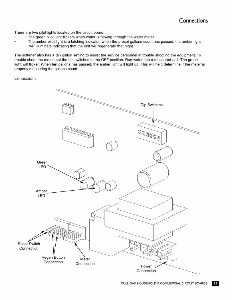
There are two pilot lights located on the circuit board.
• The green pilot light flickers when water is flowing through the water meter.
• The amber pilot light is a latching indicator, when the preset gallons count has passed, the amber light
will illuminate indicating that the unit will regenerate that night.
The softener also has a ten gallon setting to assist the service personnel in trouble shooting the equipment. To
trouble shoot the meter, set the dip switches to the OFF position. Run water into a measured pail. The green
light will flicker. When ten gallons has passed, the amber light will light up. This will help determine if the meter is
properly measuring the gallons count.
Connections
Dip Switches
Green
LED
Amber
LED
Reset Switch
Connection
Regen Button
ConnectionMeter
ConnectionPower
Connection
CCoonnnneeccttiioonnss
CULLIGAN HOUSEHOLD & COMMERCIAL CIRCUIT BOARDS36
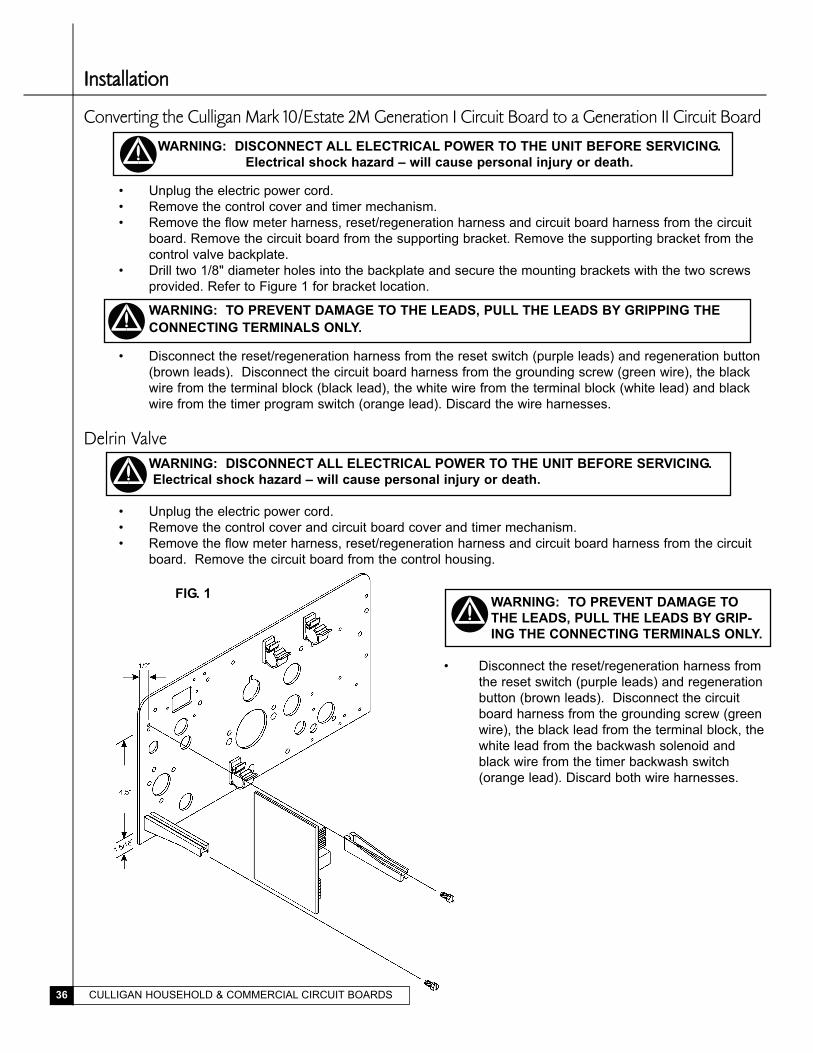
IInnssttaallllaattiioonn
Converting the Culligan Mark 10/Estate 2M Generation I Circuit Board to a Generation II Circuit Board
WARNING: DISCONNECT ALL ELECTRICAL POWER TO THE UNIT BEFORE SERVICING.
Electrical shock hazard – will cause personal injury or death.
• Unplug the electric power cord.
• Remove the control cover and timer mechanism.
• Remove the flow meter harness, reset/regeneration harness and circuit board harness from the circuit
board. Remove the circuit board from the supporting bracket. Remove the supporting bracket from the
control valve backplate.
• Drill two 1/8" diameter holes into the backplate and secure the mounting brackets with the two screws
provided. Refer to Figure 1 for bracket location.
WARNING: TO PREVENT DAMAGE TO THE LEADS, PULL THE LEADS BY GRIPPING THE
CONNECTING TERMINALS ONLY.
• Disconnect the reset/regeneration harness from the reset switch (purple leads) and regeneration button
(brown leads). Disconnect the circuit board harness from the grounding screw (green wire), the black
wire from the terminal block (black lead), the white wire from the terminal block (white lead) and black
wire from the timer program switch (orange lead). Discard the wire harnesses.
Delrin ValveWARNING: DISCONNECT ALL ELECTRICAL POWER TO THE UNIT BEFORE SERVICING.
Electrical shock hazard – will cause personal injury or death.
• Unplug the electric power cord.
• Remove the control cover and circuit board cover and timer mechanism.
• Remove the flow meter harness, reset/regeneration harness and circuit board harness from the circuit
board. Remove the circuit board from the control housing.
FIG. 1WARNING: TO PREVENT DAMAGE TO
THE LEADS, PULL THE LEADS BY GRIP-
ING THE CONNECTING TERMINALS ONLY.
• Disconnect the reset/regeneration harness from
the reset switch (purple leads) and regeneration
button (brown leads). Disconnect the circuit
board harness from the grounding screw (green
wire), the black lead from the terminal block, the
white lead from the backwash solenoid and
black wire from the timer backwash switch
(orange lead). Discard both wire harnesses.
CULLIGAN HOUSEHOLD & COMMERCIAL CIRCUIT BOARDS 37
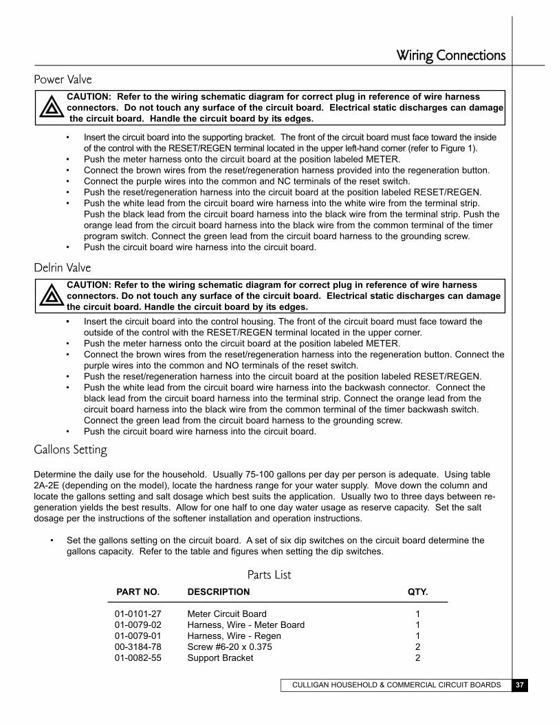
Power ValveCAUTION: Refer to the wiring schematic diagram for correct plug in reference of wire harness
connectors. Do not touch any surface of the circuit board. Electrical static discharges can damage
the circuit board. Handle the circuit board by its edges.
• Insert the circuit board into the supporting bracket. The front of the circuit board must face toward the inside
of the control with the RESET/REGEN terminal located in the upper left-hand corner (refer to Figure 1).
• Push the meter harness onto the circuit board at the position labeled METER.
• Connect the brown wires from the reset/regeneration harness provided into the regeneration button.
• Connect the purple wires into the common and NC terminals of the reset switch.
• Push the reset/regeneration harness into the circuit board at the position labeled RESET/REGEN.
• Push the white lead from the circuit board wire harness into the white wire from the terminal strip.
Push the black lead from the circuit board harness into the black wire from the terminal strip. Push the
orange lead from the circuit board harness into the black wire from the common terminal of the timer
program switch. Connect the green lead from the circuit board harness to the grounding screw.
• Push the circuit board wire harness into the circuit board.
Delrin ValveCAUTION: Refer to the wiring schematic diagram for correct plug in reference of wire harness
connectors. Do not touch any surface of the circuit board. Electrical static discharges can damage
the circuit board. Handle the circuit board by its edges.
• Insert the circuit board into the control housing. The front of the circuit board must face toward the
outside of the control with the RESET/REGEN terminal located in the upper corner.
• Push the meter harness onto the circuit board at the position labeled METER.
• Connect the brown wires from the reset/regeneration harness into the regeneration button. Connect the
purple wires into the common and NO terminals of the reset switch.
• Push the reset/regeneration harness into the circuit board at the position labeled RESET/REGEN.
• Push the white lead from the circuit board wire harness into the backwash connector. Connect the
black lead from the circuit board harness into the terminal strip. Connect the orange lead from the
circuit board harness into the black wire from the common terminal of the timer backwash switch.
Connect the green lead from the circuit board harness to the grounding screw.
• Push the circuit board wire harness into the circuit board.
Gallons Setting
Determine the daily use for the household. Usually 75-100 gallons per day per person is adequate. Using table
2A-2E (depending on the model), locate the hardness range for your water supply. Move down the column and
locate the gallons setting and salt dosage which best suits the application. Usually two to three days between re-
generation yields the best results. Allow for one half to one day water usage as reserve capacity. Set the salt
dosage per the instructions of the softener installation and operation instructions.
• Set the gallons setting on the circuit board. A set of six dip switches on the circuit board determine the
gallons capacity. Refer to the table and figures when setting the dip switches.
WWiirriinngg CCoonnnneeccttiioonnss
Parts ListPART NO. DESCRIPTION QTY.
01-0101-27 Meter Circuit Board 1
01-0079-02 Harness, Wire - Meter Board 1
01-0079-01 Harness, Wire - Regen 1
00-3184-78 Screw #6-20 x 0.375 2
01-0082-55 Support Bracket 2
CULLIGAN HOUSEHOLD & COMMERCIAL CIRCUIT BOARDS38
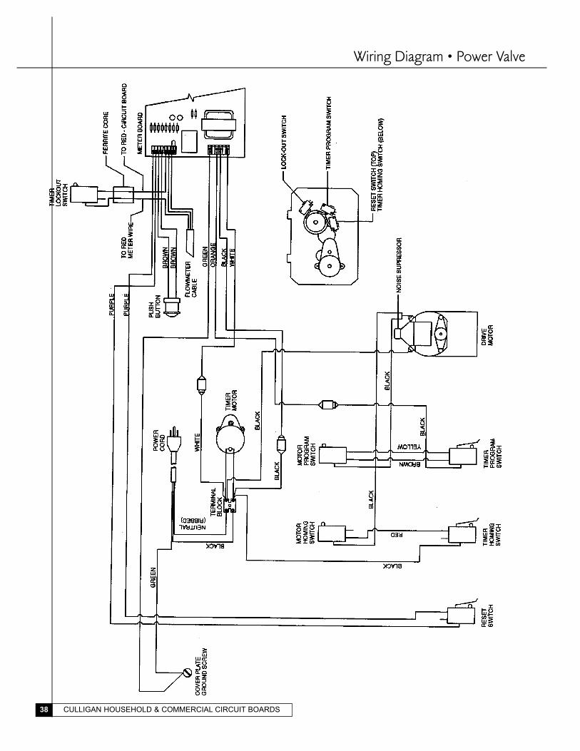
Wiring Diagram • Power Valve
CULLIGAN HOUSEHOLD & COMMERCIAL CIRCUIT BOARDS 39
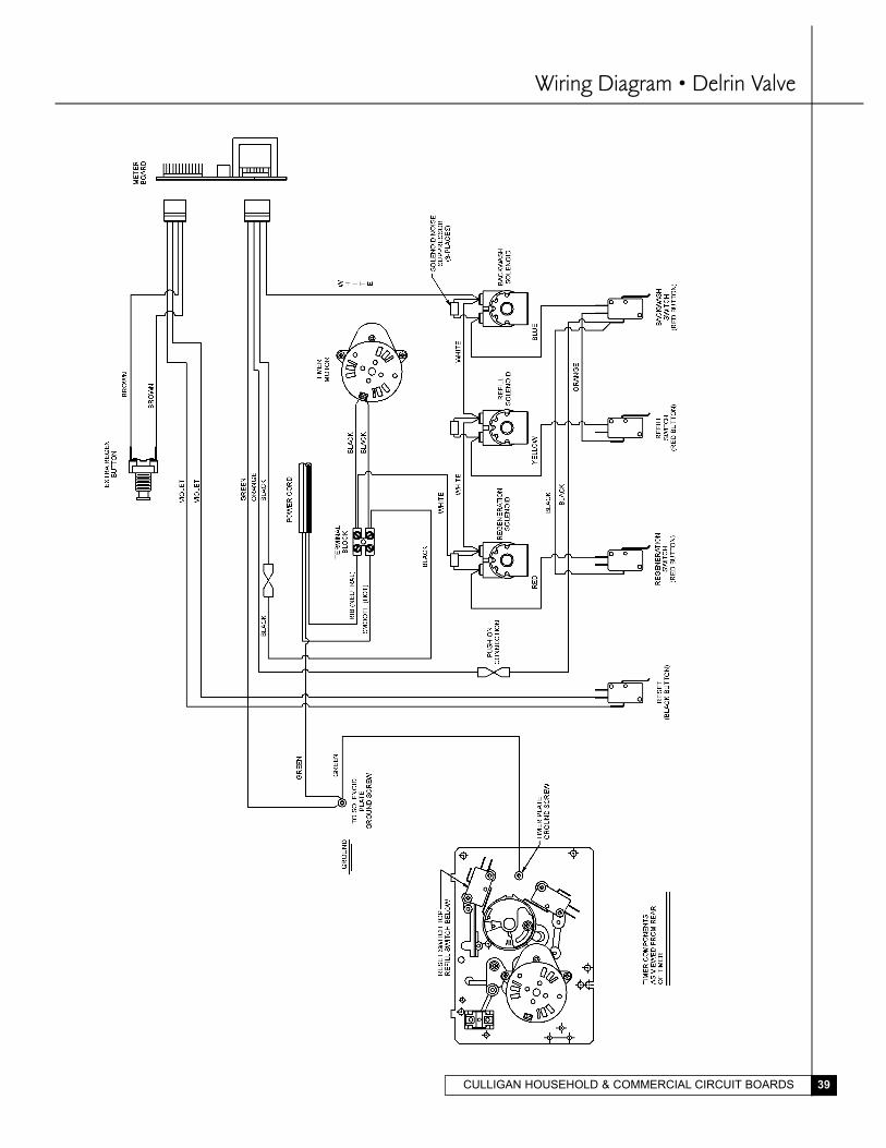
Wiring Diagram • Delrin Valve
CULLIGAN HOUSEHOLD & COMMERCIAL CIRCUIT BOARDS40
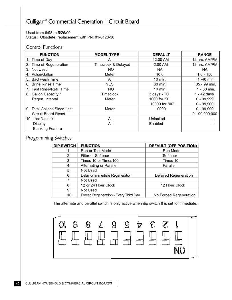
CCuulllliiggaann® CCoommmmeerrcciiaall GGeenneerraattiioonn II CCiirrccuuiitt BBooaarrdd
Used from 6/98 to 5/26/00
Status: Obsolete, replacement with PN: 01-0128-38
Control FunctionsFUNCTION MODEL TYPE DEFAULT RANGE
1. Time of Day All 12:00 AM 12 hrs. AM/PM
2. Time of Regeneration Timeclock & Delayed 2:00 AM 12 hrs. AM/PM
3. Not Used NO NA NA
4. Pulse/Gallon Meter 10.0 1.0 - 150
5. Backwash Time All 10 min. 1 -40 min.
6. Brine Rinse Time YES 60 min. 35 - 99 min.
7. Fast Rinse/Refill Time NO 10 min 1 - 30 min.
8. Gallon Capacity / Timeclock 3 days - TC 1 - 42 days
Regen. Interval Meter 1000 for "0" 0 - 99,999
10000 for "00" 0 - 99,900
9. Total Gallons Since Last Meter 0000 0 - 99,999
Circuit Board Reset 0 - 99,999,000
10. Lock/Unlock All Unlocked --
Display All Enabled --
Blanking Feature
Programming SwitchesDIP SWITCH FUNCTION DEFAULT (OFF POSITION)
1 Run or Test Mode Run Mode
2 Filter or Softener Softener
3 Times 10 or Times100 Times 10
4 Alternating or Parallel Parallel
5 Not Used
6 Delay or Immediate Regeneration Delayed Regeneration
7 Not Used
8 12 or 24 Hour Clock 12 Hour Clock
9 Not Used
10 Forced Regeneration - Every Third Day No Forced Regeneration
The alternate and parallel switch is only active when dip switch 6 is set to immediate.
CULLIGAN HOUSEHOLD & COMMERCIAL CIRCUIT BOARDS 41
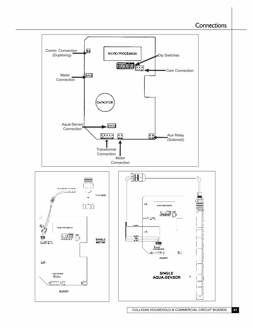
CCoonnnneeccttiioonnss
®
Comm. Connection
(Duplexing)
Meter
Connection
Aqua-Sensor
Connection
Transformer
ConnectionMotor
Connection
Aux Relay
(Solenoid)
Cam Connection
Dip Switches
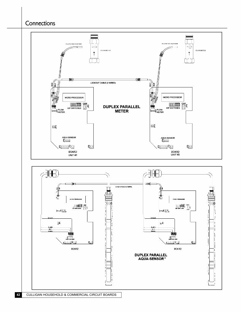
CULLIGAN HOUSEHOLD & COMMERCIAL CIRCUIT BOARDS42
®
CCoonnnneeccttiioonnss
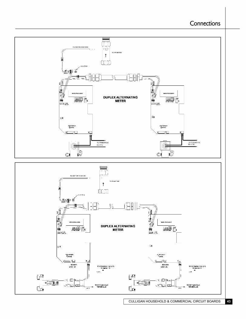
CULLIGAN HOUSEHOLD & COMMERCIAL CIRCUIT BOARDS 43
CCoonnnneeccttiioonnss

CULLIGAN HOUSEHOLD & COMMERCIAL CIRCUIT BOARDS44
1. Turn on the power to the control.
2. Display will be flashing.
3. Press status twice; 12:00 PM will appear, this is the time of day, adjust using the up and down arrows. A num-
ber "1" will appear at the bottom of the display while in this mode.
4. Press status again, this displays the time of regeneration for time clock and delayed units, adjust using the up
and down arrows. A number "2" will appear at the bottom of the display while in this mode.
5. Press status again, this displays the number of pulses/gallon (K factor) for units with a flowmeter only. All
other units will skip this step. Again this setting can be adjusted using the up and down arrows.
6. Press status again, this displays the backwash time in minutes. The setting can be adjusted using the up and
down arrows. A number "5" will appear at the bottom of the display while in this mode.
7. Press status again, this displays the brine draw/slow rinse time in minutes. The settings can be adjusted using
the up and down arrows. A number "6" will appear at the bottom of the display while in this mode.
8. Press status again, this displays the fast rinse/refill time in minutes. The setting can be adjusted using the up
and down arrows. A number "7" will appear at the bottom of the display while in this mode.
Press � to increase or
� to decrease
Press � to increase or
� to decrease
Press � to increase or
� to decrease
Press � to increase or
� to decrease
Press � to increase or
� to decrease
Press � to increase or
� to decrease
PPrrooggrraammmmiinngg
CULLIGAN HOUSEHOLD & COMMERCIAL CIRCUIT BOARDS 45
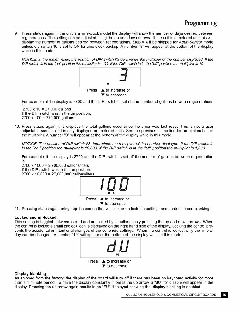
9. Press status again, if the unit is a time-clock model the display will show the number of days desired betweenregenerations. The setting can be adjusted using the up and down arrows. If the unit is a metered unit this willdisplay the number of gallons desired between regenerations. Step 8 will be skipped for Aqua-Sensor modeunless dip switch 10 is set to ON for time clock backup. A number "8" will appear at the bottom of the displaywhile in this mode.
NOTICE: In the meter mode, the position of DIP switch #3 determines the multiplier of the number displayed. If theDIP switch is in the "on" position the multiplier is 100. If the DIP switch is in the "off" position the multiplier is 10.
For example, if the display is 2700 and the DIP switch is set off the number of gallons between regenerationsis:2700 x 10 = 27,000 gallons
If the DIP switch was in the on position:2700 x 100 = 270,000 gallons
10. Press status again, this displays the total gallons used since the timer was last reset. This is not a useradjustable screen, and is only displayed on metered units. See the previous instruction for an explanation ofthe multiplier. A number "9" will appear at the bottom of the display while in this mode.
NOTICE: The position of DIP switch #3 determines the multiplier of the number displayed. If the DIP switch isin the "on " position the multiplier is 10,000. If the DIP switch is in the "off" position the multiplier is 1,000.
For example, if the display is 2700 and the DIP switch is set off the number of gallons between regenerationis:2700 x 1000 = 2,700,000 gallons/litersIf the DIP switch was in the on position:2700 x 10,000 = 27,000,000 gallons/liters
11. Pressing status again brings up the screen that will lock or un-lock the settings and control screen blanking.
Locked and un-lockedThis setting is toggled between locked and un-locked by simultaneously pressing the up and down arrows. Whenthe control is locked a small padlock icon is displayed on the right hand side of the display. Locking the control pre-vents the accidental or intentional changes of the softeners settings. When the control is locked, only the time ofday can be changed. A number "10" will appear at the bottom of the display while in this mode.
Display blankingAs shipped from the factory, the display of the board will turn off if there has been no keyboard activity for morethan a 1 minute period. To have the display constantly lit press the up arrow, a “dU” for disable will appear in thedisplay. Pressing the up arrow again results in an “EU” displayed showing that display blanking is enabled.
Press � to increase or
� to decrease
Press � to increase or
� to decrease
Press � to increase or
� to decrease
99
PPrrooggrraammmmiinngg
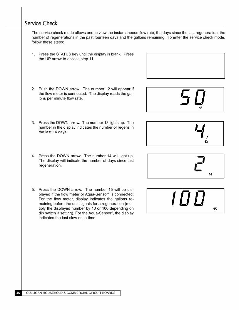
CULLIGAN HOUSEHOLD & COMMERCIAL CIRCUIT BOARDS46
The service check mode allows one to view the instantaneous flow rate, the days since the last regeneration, the
number of regenerations in the past fourteen days and the gallons remaining. To enter the service check mode,
follow these steps:
1. Press the STATUS key until the display is blank. Press
the UP arrow to access step 11.
2. Push the DOWN arrow. The number 12 will appear if
the flow meter is connected. The display reads the gal-
lons per minute flow rate.
SSeerrvviiccee CChheecckk
3. Press the DOWN arrow. The number 13 lights up. The
number in the display indicates the number of regens in
the last 14 days.
5. Press the DOWN arrow. The number 15 will be dis-
played if the flow meter or Aqua-Sensor® is connected.
For the flow meter, display indicates the gallons re-
maining before the unit signals for a regeneration (mul-
tiply the displayed number by 10 or 100 depending on
dip switch 3 setting). For the Aqua-Sensor®, the display
indicates the last slow rinse time.
4. Press the DOWN arrow. The number 14 will light up.
The display will indicate the number of days since last
regeneration.
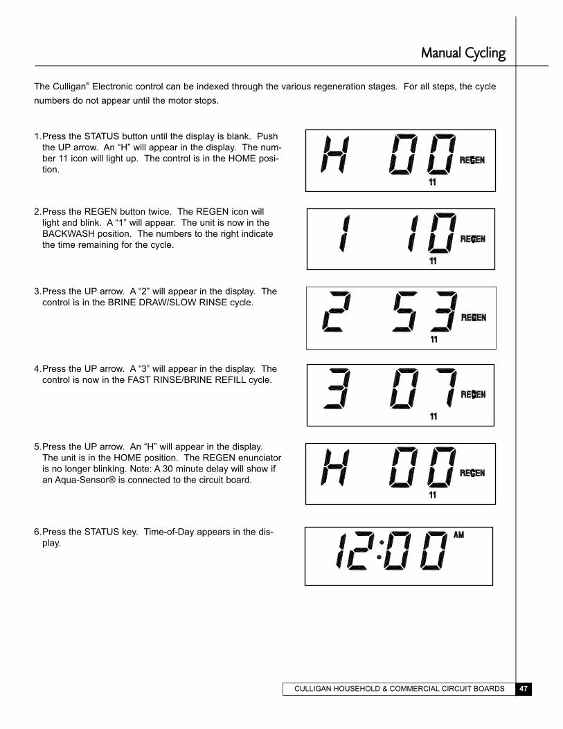
CULLIGAN HOUSEHOLD & COMMERCIAL CIRCUIT BOARDS 47
The Culligan® Electronic control can be indexed through the various regeneration stages. For all steps, the cycle
numbers do not appear until the motor stops.
2.Press the REGEN button twice. The REGEN icon will
light and blink. A “1” will appear. The unit is now in the
BACKWASH position. The numbers to the right indicate
the time remaining for the cycle.
3.Press the UP arrow. A “2” will appear in the display. The
control is in the BRINE DRAW/SLOW RINSE cycle.
4.Press the UP arrow. A “3” will appear in the display. The
control is now in the FAST RINSE/BRINE REFILL cycle.
5.Press the UP arrow. An “H” will appear in the display.
The unit is in the HOME position. The REGEN enunciator
is no longer blinking. Note: A 30 minute delay will show if
an Aqua-Sensor® is connected to the circuit board.
MMaannuuaall CCyycclliinngg
1.Press the STATUS button until the display is blank. Push
the UP arrow. An “H” will appear in the display. The num-
ber 11 icon will light up. The control is in the HOME posi-
tion.
6.Press the STATUS key. Time-of-Day appears in the dis-
play.
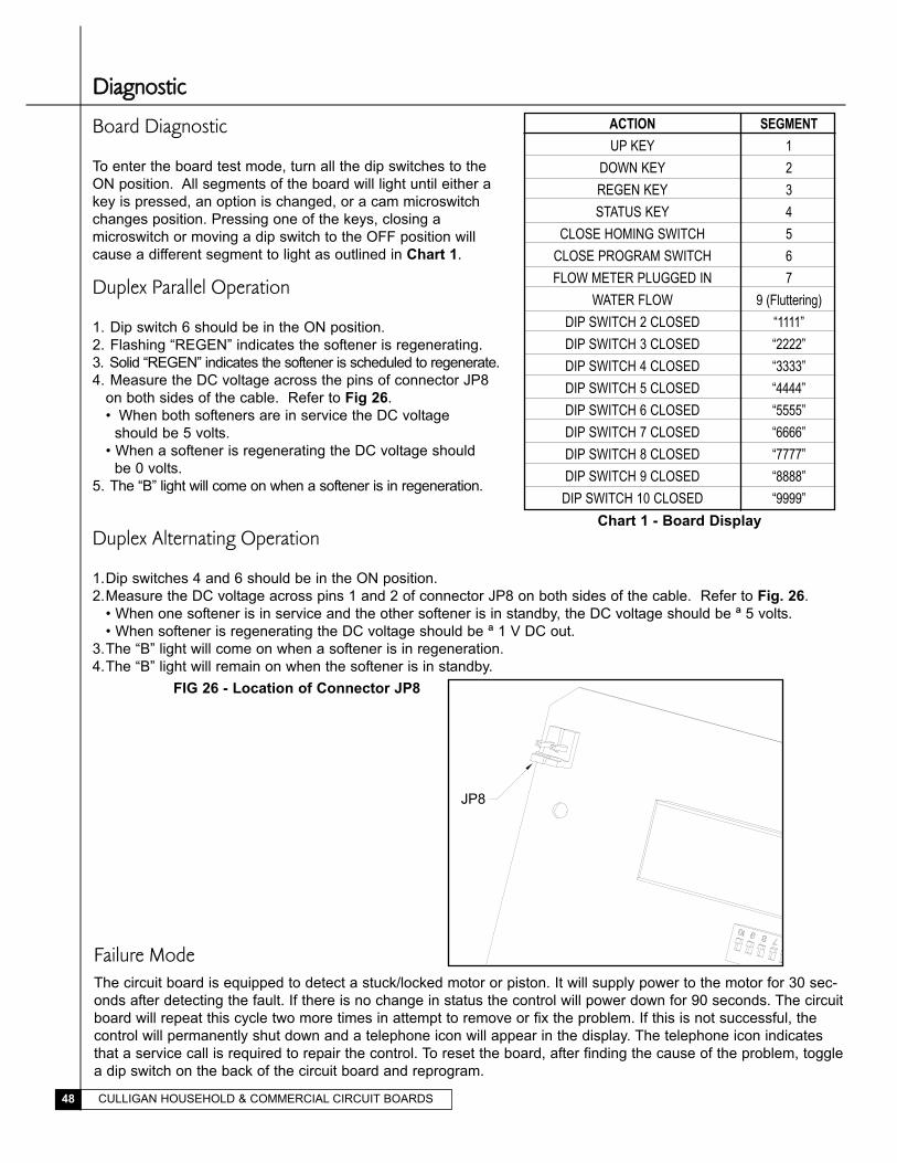
CULLIGAN HOUSEHOLD & COMMERCIAL CIRCUIT BOARDS48
Board Diagnostic
To enter the board test mode, turn all the dip switches to the
ON position. All segments of the board will light until either a
key is pressed, an option is changed, or a cam microswitch
changes position. Pressing one of the keys, closing a
microswitch or moving a dip switch to the OFF position will
cause a different segment to light as outlined in Chart 1.
Duplex Parallel Operation
1. Dip switch 6 should be in the ON position.
2. Flashing “REGEN” indicates the softener is regenerating.
3. Solid “REGEN” indicates the softener is scheduled to regenerate.
4. Measure the DC voltage across the pins of connector JP8
on both sides of the cable. Refer to Fig 26.
• When both softeners are in service the DC voltage
should be 5 volts.
• When a softener is regenerating the DC voltage should
be 0 volts.
5. The “B” light will come on when a softener is in regeneration.
ACTIONUP KEY
DOWN KEYREGEN KEYSTATUS KEY
CLOSE HOMING SWITCHCLOSE PROGRAM SWITCHFLOW METER PLUGGED IN
WATER FLOWDIP SWITCH 2 CLOSEDDIP SWITCH 3 CLOSEDDIP SWITCH 4 CLOSEDDIP SWITCH 5 CLOSEDDIP SWITCH 6 CLOSEDDIP SWITCH 7 CLOSEDDIP SWITCH 8 CLOSEDDIP SWITCH 9 CLOSEDDIP SWITCH 10 CLOSED
SEGMENT
1
2
3
4
5
6
7
9 (Fluttering)
“1111”
“2222”
“3333”
“4444”
“5555”
“6666”
“7777”
“8888”
“9999”
Duplex Alternating Operation
1.Dip switches 4 and 6 should be in the ON position.
2.Measure the DC voltage across pins 1 and 2 of connector JP8 on both sides of the cable. Refer to Fig. 26.
• When one softener is in service and the other softener is in standby, the DC voltage should be ª 5 volts.
• When softener is regenerating the DC voltage should be ª 1 V DC out.
3.The “B” light will come on when a softener is in regeneration.
4.The “B” light will remain on when the softener is in standby.
Chart 1 - Board Display
DDiiaaggnnoossttiicc
FIG 26 - Location of Connector JP8
Failure ModeThe circuit board is equipped to detect a stuck/locked motor or piston. It will supply power to the motor for 30 sec-
onds after detecting the fault. If there is no change in status the control will power down for 90 seconds. The circuit
board will repeat this cycle two more times in attempt to remove or fix the problem. If this is not successful, the
control will permanently shut down and a telephone icon will appear in the display. The telephone icon indicates
that a service call is required to repair the control. To reset the board, after finding the cause of the problem, toggle
a dip switch on the back of the circuit board and reprogram.
JP8
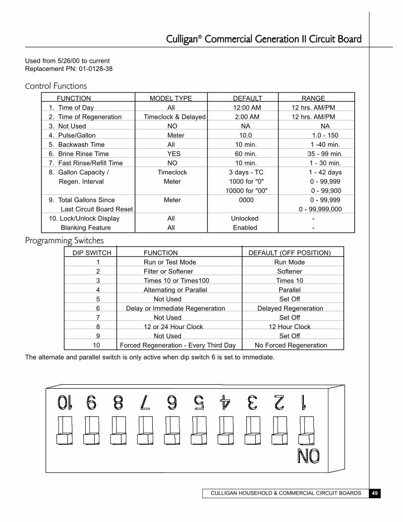
CULLIGAN HOUSEHOLD & COMMERCIAL CIRCUIT BOARDS 49
CCuulllliiggaann® CCoommmmeerrcciiaall GGeenneerraattiioonn IIII CCiirrccuuiitt BBooaarrdd
Used from 5/26/00 to current
Replacement PN: 01-0128-38
Control FunctionsFUNCTION MODEL TYPE DEFAULT RANGE
1. Time of Day All 12:00 AM 12 hrs. AM/PM
2. Time of Regeneration Timeclock & Delayed 2:00 AM 12 hrs. AM/PM
3. Not Used NO NA NA
4. Pulse/Gallon Meter 10.0 1.0 - 150
5. Backwash Time All 10 min. 1 -40 min.
6. Brine Rinse Time YES 60 min. 35 - 99 min.
7. Fast Rinse/Refill Time NO 10 min. 1 - 30 min.
8. Gallon Capacity / Timeclock 3 days - TC 1 - 42 days
Regen. Interval Meter 1000 for "0" 0 - 99,999
10000 for "00" 0 - 99,900
9. Total Gallons Since Meter 0000 0 - 99,999
Last Circuit Board Reset 0 - 99,999,000
10. Lock/Unlock Display All Unlocked -
Blanking Feature All Enabled -
Programming SwitchesDIP SWITCH FUNCTION DEFAULT (OFF POSITION)
1 Run or Test Mode Run Mode
2 Filter or Softener Softener
3 Times 10 or Times100 Times 10
4 Alternating or Parallel Parallel
5 Not Used Set Off
6 Delay or Immediate Regeneration Delayed Regeneration
7 Not Used Set Off
8 12 or 24 Hour Clock 12 Hour Clock
9 Not Used Set Off
10 Forced Regeneration - Every Third Day No Forced Regeneration
The alternate and parallel switch is only active when dip switch 6 is set to immediate.
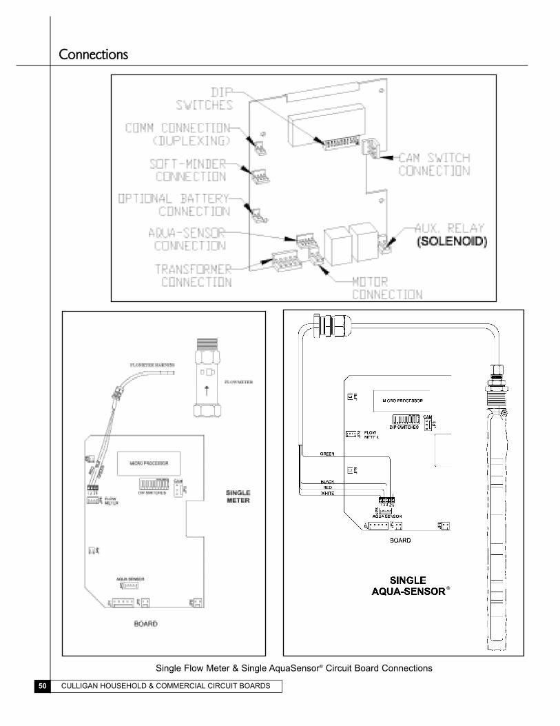
CULLIGAN HOUSEHOLD & COMMERCIAL CIRCUIT BOARDS50
CCoonnnneeccttiioonnss
Single Flow Meter & Single AquaSensor® Circuit Board Connections
®
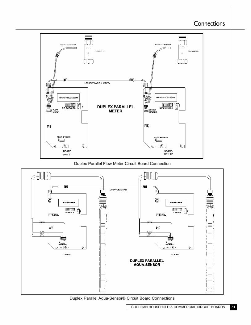
CULLIGAN HOUSEHOLD & COMMERCIAL CIRCUIT BOARDS 51
Duplex Parallel Flow Meter Circuit Board Connection
Duplex Parallel Aqua-Sensor® Circuit Board Connections
CCoonnnneeccttiioonnss
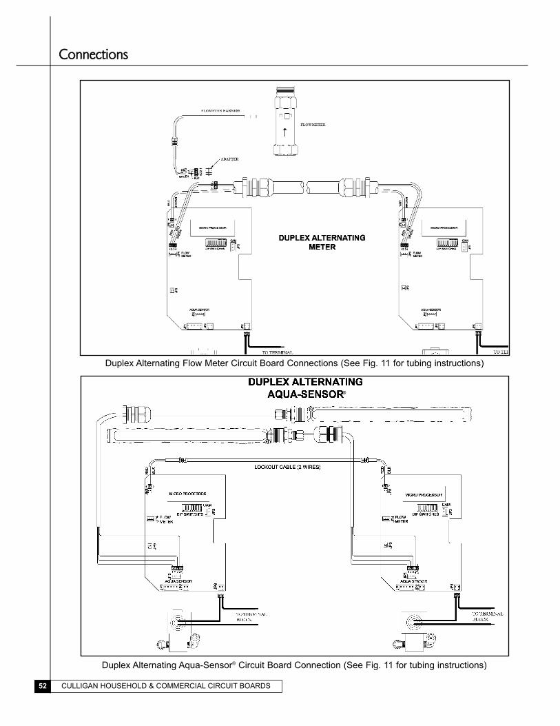
CULLIGAN HOUSEHOLD & COMMERCIAL CIRCUIT BOARDS52
Duplex Alternating Aqua-Sensor® Circuit Board Connection (See Fig. 11 for tubing instructions)
Duplex Alternating Flow Meter Circuit Board Connections (See Fig. 11 for tubing instructions)
®
CCoonnnneeccttiioonnss
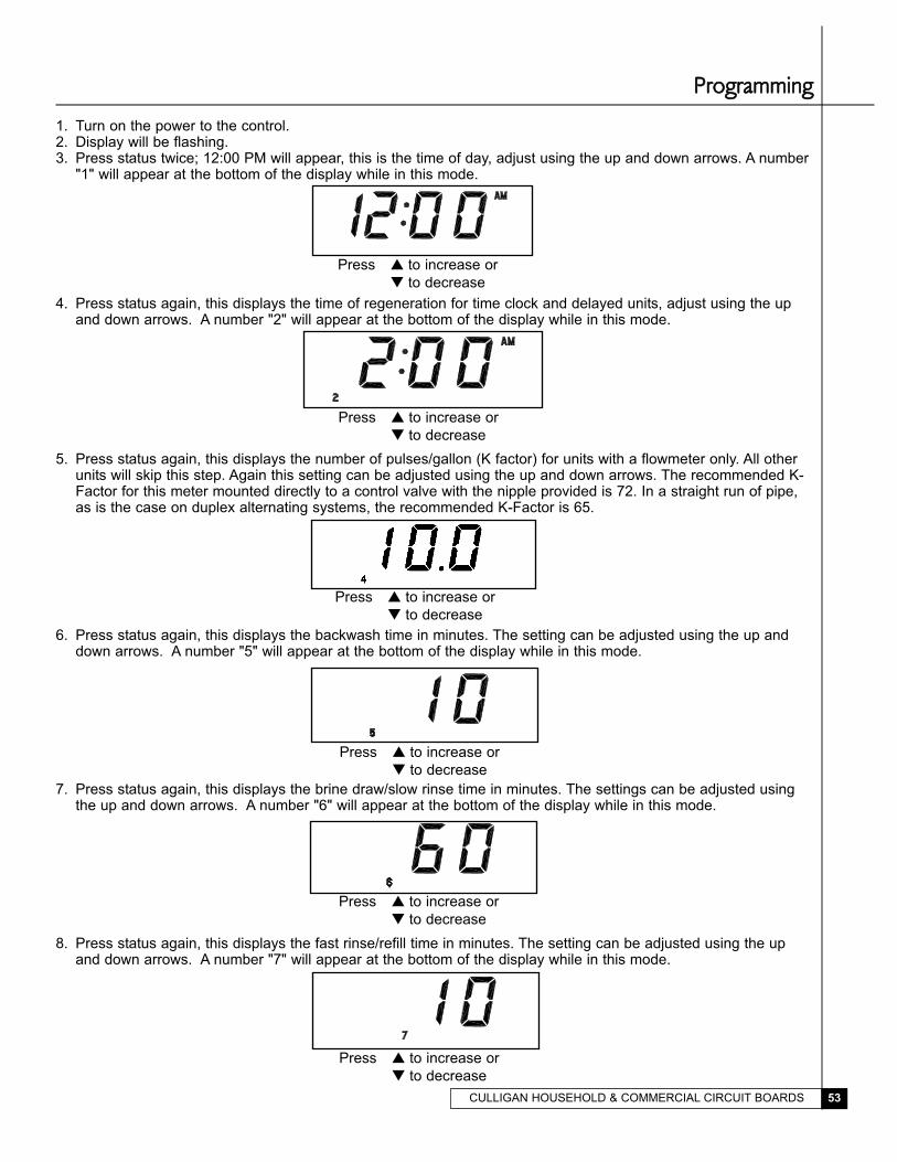
CULLIGAN HOUSEHOLD & COMMERCIAL CIRCUIT BOARDS 53
1. Turn on the power to the control.2. Display will be flashing.3. Press status twice; 12:00 PM will appear, this is the time of day, adjust using the up and down arrows. A number
"1" will appear at the bottom of the display while in this mode.
4. Press status again, this displays the time of regeneration for time clock and delayed units, adjust using the upand down arrows. A number "2" will appear at the bottom of the display while in this mode.
5. Press status again, this displays the number of pulses/gallon (K factor) for units with a flowmeter only. All otherunits will skip this step. Again this setting can be adjusted using the up and down arrows. The recommended K-Factor for this meter mounted directly to a control valve with the nipple provided is 72. In a straight run of pipe,as is the case on duplex alternating systems, the recommended K-Factor is 65.
6. Press status again, this displays the backwash time in minutes. The setting can be adjusted using the up anddown arrows. A number "5" will appear at the bottom of the display while in this mode.
7. Press status again, this displays the brine draw/slow rinse time in minutes. The settings can be adjusted usingthe up and down arrows. A number "6" will appear at the bottom of the display while in this mode.
8. Press status again, this displays the fast rinse/refill time in minutes. The setting can be adjusted using the upand down arrows. A number "7" will appear at the bottom of the display while in this mode.
Press � to increase or
� to decrease
Press � to increase or
� to decrease
Press � to increase or
� to decrease
Press � to increase or
� to decrease
Press � to increase or
� to decrease
PPrrooggrraammmmiinngg
Press � to increase or
� to decrease
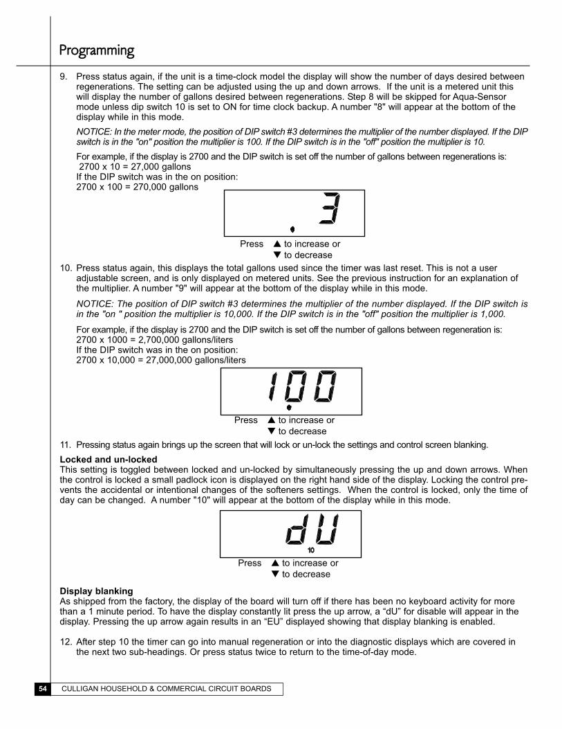
CULLIGAN HOUSEHOLD & COMMERCIAL CIRCUIT BOARDS54
9. Press status again, if the unit is a time-clock model the display will show the number of days desired betweenregenerations. The setting can be adjusted using the up and down arrows. If the unit is a metered unit thiswill display the number of gallons desired between regenerations. Step 8 will be skipped for Aqua-Sensormode unless dip switch 10 is set to ON for time clock backup. A number "8" will appear at the bottom of thedisplay while in this mode.
NOTICE: In the meter mode, the position of DIP switch #3 determines the multiplier of the number displayed. If the DIPswitch is in the "on" position the multiplier is 100. If the DIP switch is in the "off" position the multiplier is 10.For example, if the display is 2700 and the DIP switch is set off the number of gallons between regenerations is:2700 x 10 = 27,000 gallons
If the DIP switch was in the on position:2700 x 100 = 270,000 gallons
10. Press status again, this displays the total gallons used since the timer was last reset. This is not a useradjustable screen, and is only displayed on metered units. See the previous instruction for an explanation ofthe multiplier. A number "9" will appear at the bottom of the display while in this mode.
NOTICE: The position of DIP switch #3 determines the multiplier of the number displayed. If the DIP switch isin the "on " position the multiplier is 10,000. If the DIP switch is in the "off" position the multiplier is 1,000.
For example, if the display is 2700 and the DIP switch is set off the number of gallons between regeneration is:2700 x 1000 = 2,700,000 gallons/litersIf the DIP switch was in the on position:2700 x 10,000 = 27,000,000 gallons/liters
11. Pressing status again brings up the screen that will lock or un-lock the settings and control screen blanking.
Locked and un-lockedThis setting is toggled between locked and un-locked by simultaneously pressing the up and down arrows. Whenthe control is locked a small padlock icon is displayed on the right hand side of the display. Locking the control pre-vents the accidental or intentional changes of the softeners settings. When the control is locked, only the time ofday can be changed. A number "10" will appear at the bottom of the display while in this mode.
Display blankingAs shipped from the factory, the display of the board will turn off if there has been no keyboard activity for morethan a 1 minute period. To have the display constantly lit press the up arrow, a “dU” for disable will appear in thedisplay. Pressing the up arrow again results in an “EU” displayed showing that display blanking is enabled.
12. After step 10 the timer can go into manual regeneration or into the diagnostic displays which are covered inthe next two sub-headings. Or press status twice to return to the time-of-day mode.
Press � to increase or
� to decrease
Press � to increase or
� to decrease
Press � to increase or
� to decrease
PPrrooggrraammmmiinngg
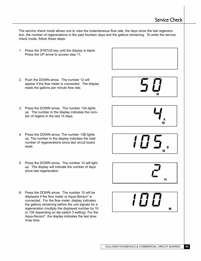
CULLIGAN HOUSEHOLD & COMMERCIAL CIRCUIT BOARDS 55
The service check mode allows one to view the instantaneous flow rate, the days since the last regenera-
tion, the number of regenerations in the past fourteen days and the gallons remaining. To enter the service
check mode, follow these steps:
1. Press the STATUS key until the display is blank.
Press the UP arrow to access step 11.
2. Push the DOWN arrow. The number 12 will
appear if the flow meter is connected. The display
reads the gallons per minute flow rate.
SSeerrvviiccee CChheecckk
3. Press the DOWN arrow. The number 13A lights
up. The number in the display indicates the num-
ber of regens in the last 14 days.
4. Press the DOWN arrow. The number 13B lights
up. The number in the display indicates the total
number of regenerations since last circuit board
reset.
5. Press the DOWN arrow. The number 14 will light
up. The display will indicate the number of days
since last regeneration.
6. Press the DOWN arrow. The number 15 will be
displayed if the flow meter or Aqua-Sensor® is
connected. For the flow meter, display indicates
the gallons remaining before the unit signals for a
regeneration (multiply the displayed number by 10
or 100 depending on dip switch 3 setting). For the
Aqua-Sensor®, the display indicates the last slow
rinse time.
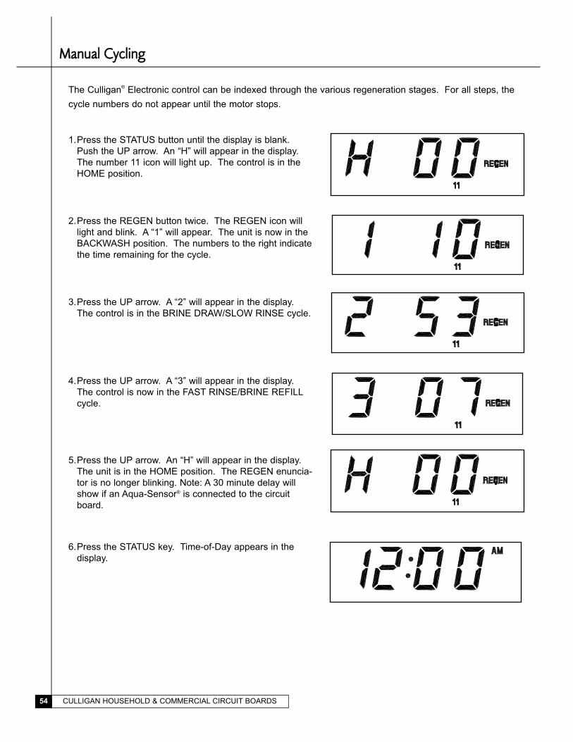
The Culligan® Electronic control can be indexed through the various regeneration stages. For all steps, the
cycle numbers do not appear until the motor stops.
2.Press the REGEN button twice. The REGEN icon will
light and blink. A “1” will appear. The unit is now in the
BACKWASH position. The numbers to the right indicate
the time remaining for the cycle.
3.Press the UP arrow. A “2” will appear in the display.
The control is in the BRINE DRAW/SLOW RINSE cycle.
4.Press the UP arrow. A “3” will appear in the display.
The control is now in the FAST RINSE/BRINE REFILL
cycle.
5.Press the UP arrow. An “H” will appear in the display.
The unit is in the HOME position. The REGEN enuncia-
tor is no longer blinking. Note: A 30 minute delay will
show if an Aqua-Sensor® is connected to the circuit
board.
MMaannuuaall CCyycclliinngg
1.Press the STATUS button until the display is blank.
Push the UP arrow. An “H” will appear in the display.
The number 11 icon will light up. The control is in the
HOME position.
6.Press the STATUS key. Time-of-Day appears in the
display.
CULLIGAN HOUSEHOLD & COMMERCIAL CIRCUIT BOARDS54
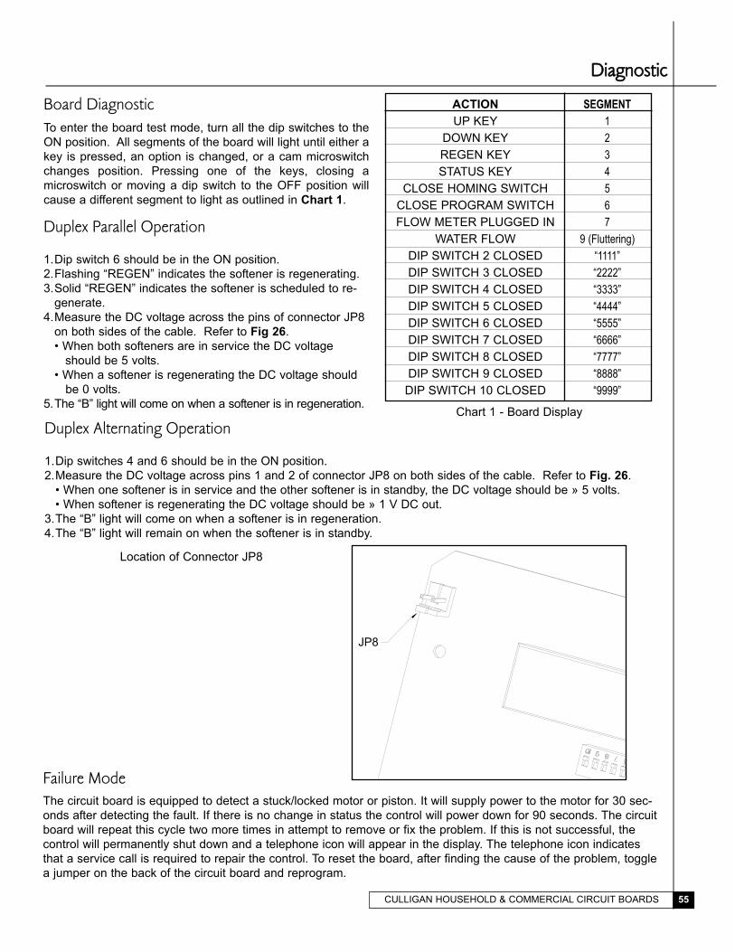
Board DiagnosticTo enter the board test mode, turn all the dip switches to the
ON position. All segments of the board will light until either a
key is pressed, an option is changed, or a cam microswitch
changes position. Pressing one of the keys, closing a
microswitch or moving a dip switch to the OFF position will
cause a different segment to light as outlined in Chart 1.
Duplex Parallel Operation
1.Dip switch 6 should be in the ON position.
2.Flashing “REGEN” indicates the softener is regenerating.
3.Solid “REGEN” indicates the softener is scheduled to re-
generate.
4.Measure the DC voltage across the pins of connector JP8
on both sides of the cable. Refer to Fig 26.
• When both softeners are in service the DC voltage
should be 5 volts.
• When a softener is regenerating the DC voltage should
be 0 volts.
5.The “B” light will come on when a softener is in regeneration.
ACTION
UP KEY
DOWN KEY
REGEN KEY
STATUS KEY
CLOSE HOMING SWITCH
CLOSE PROGRAM SWITCH
FLOW METER PLUGGED IN
WATER FLOW
DIP SWITCH 2 CLOSED
DIP SWITCH 3 CLOSED
DIP SWITCH 4 CLOSED
DIP SWITCH 5 CLOSED
DIP SWITCH 6 CLOSED
DIP SWITCH 7 CLOSED
DIP SWITCH 8 CLOSED
DIP SWITCH 9 CLOSED
DIP SWITCH 10 CLOSED
SEGMENT
1
2
3
4
5
6
7
9 (Fluttering)
“1111”
“2222”
“3333”
“4444”
“5555”
“6666”
“7777”
“8888”
“9999”
Duplex Alternating Operation
1.Dip switches 4 and 6 should be in the ON position.
2.Measure the DC voltage across pins 1 and 2 of connector JP8 on both sides of the cable. Refer to Fig. 26.
• When one softener is in service and the other softener is in standby, the DC voltage should be » 5 volts.
• When softener is regenerating the DC voltage should be » 1 V DC out.
3.The “B” light will come on when a softener is in regeneration.
4.The “B” light will remain on when the softener is in standby.
Chart 1 - Board Display
DDiiaaggnnoossttiicc
Location of Connector JP8
Failure ModeThe circuit board is equipped to detect a stuck/locked motor or piston. It will supply power to the motor for 30 sec-
onds after detecting the fault. If there is no change in status the control will power down for 90 seconds. The circuit
board will repeat this cycle two more times in attempt to remove or fix the problem. If this is not successful, the
control will permanently shut down and a telephone icon will appear in the display. The telephone icon indicates
that a service call is required to repair the control. To reset the board, after finding the cause of the problem, toggle
a jumper on the back of the circuit board and reprogram.
JP8
CULLIGAN HOUSEHOLD & COMMERCIAL CIRCUIT BOARDS 55