hose reel cart - tricamindustries.com · manual del usuario modelo hr300 10/10 • instrucciones de...
TRANSCRIPT
Manual del UsuarioModelo HR300
10/10
• Instrucciones de Seguridad Importantes• Instrucciones de Ensamblaje• Identificación de Piezas y Herrajes
Preguntas sobre el producto:Tricam7677 Equitable DriveEden Prairie, MN 55344800-867-6763www.tricam.com
PRECAUCIÓN:Leer, entender y seguir TODAS las instrucciones antes de usar este producto.
¿¿PPrreegguunnttaass,, pprroobblleemmaass oo ppiieezzaass ffaallttaanntteess?? Antes de volver al minorista, visita nuestro sitio en Internetwwwwww..ttrriiccaamm..ccoommy llena el formulario de solicitud de piezas de repuesto o llama a nuestro departamento deservicio al cliente al 11--880000--886677--66776633, de Lunes a Viernes entre las 9 a.m. y 4 p.m., Hora Estándar del Centro9 a.m. - 4 p.m., CST, Monday-Friday.
Carrito con Carrete Para Manguera
Owners ManualModel HR300
10/10
• Important Safety Instructions• Assembly Instructions• Parts and Hardware Identification
For product inquiries:Tricam7677 Equitable DriveEden Prairie, MN 55344800-867-6763www.tricam.com
CAUTION: Read, understand and follow ALL instructions before using this product.
QQuueessttiioonnss,, pprroobblleemmss,, oorr mmiissssiinngg ppaarrttss?? Before returning to your retailer, visit us online at wwwwww..ttrriiccaamm..ccoomm andcomplete the replacement parts submission form or call our customer service department at 11--880000--886677--66776633,9 a.m. - 4 p.m., CST, Monday-Friday.
Hose Reel Cart
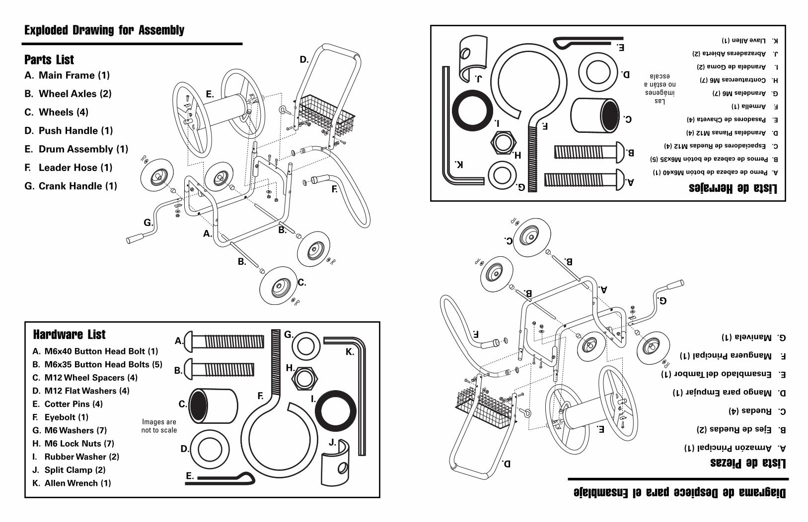
A. Main Frame (1)
B. Wheel Axles (2)
C. Wheels (4)
D. Push Handle (1)
E. Drum Assembly (1)
F. Leader Hose (1)
G. Crank Handle (1)
Exploded Drawing for Assembly
Parts List
A. M6x40 Button Head Bolt (1)
B. M6x35 Button Head Bolts (5)
C. M12 Wheel Spacers (4)
D. M12 Flat Washers (4)
E. Cotter Pins (4)
F. Eyebolt (1)
G. M6 Washers (7)
H. M6 Lock Nuts (7)
I. Rubber Washer (2)
J. Split Clamp (2)
K. Allen Wrench (1)
Hardware List
Images arenot to scale
A.
B.
D.
C.
E.
G.
A.
B.
D.
C.
E.
F.
G.
H.
I.
J.
F.
B.
A.Armazón Principal (1)
B.Ejes de Ruedas (2)
C.Ruedas (4)
D.Mango para Empujar (1)
E.Ensamblado del Tambor (1)
F.Manguera Principal (1)
G.Manivela (1)
Diagrama de Despiece para el Ensamblaje
Lista de Piezas
A.Perno de cabeza de botón M6x40 (1)
B.Pernos de cabeza de botón M6x35 (5)
C.Espaciadores de Ruedas M12 (4)
D.Arandelas Planas M12 (4)
E.Pasadores de Chaveta (4)
F.Armella (1)
G.Arandelas M6 (7)
H.Contratuercas M6 (7)
I.Arandela de Goma (2)
J.Abrazaderas Abierta (2)
K.Llave Allen (1)
Lista de Herrajes
Lasimágenesno están a
escala
A.
B.
D.
C.
E.
G.
A.
B.
D.
C.
E.
F.
G.
H.
I.
J.
F.
B.
K.K.
1.LEER CON CUIDADO TODAS LAS INSTRUCCIONES ANTES DE USAR. Si estas instrucciones no se entienden, onecesitan ser aclaradas o explicadas aún más, por favor, llamar a nuestra línea de asistencia gratuita al 11--880000--886677--66776633de Lunes a Viernes de 9:00 a.m. a 4:00 p.m., Hora Estándar del Centro.
2.No cargar más de 300 pies (91,4m) de manguera.3.Distribuir la manguera de manera uniforme sobre la superficie del ensamblado del tambor.4.Si alguna de las piezas se daña, rompe o pierde; no usar el carrito con carrete para manguera hasta reparar la pieza u
obtener una de repuesto.5.No usar el carrito sobre superficies que puedan dañar las ruedas. NNoo iinnffllaarr llooss nneeuummááttiiccooss aa mmááss ddee 3300 PPSSII ((22,,0077 BBAARR))..6.Recomendamos revisar el carrito después de cada uso para detectar cualquier daño.9.GGUUAARRDDAARR EESSTTAASS IINNSSTTRRUUCCCCIIOONNEESS PPAARRAA FFUUTTUURRAASS CCOONNSSUULLTTAASS..
El carrito con carrete para manguera necesita ensamblarse. Antes de empezar el ensamblaje, revisar si están todas laspiezas y herrajes. Si alguna falta o está dañada, o existe cualquier duda o se necesitan más instrucciones NO DEVOLVERESTE PRODUCTO AL MINORISTA: visitar nuestro sitio wwwwww..ttrriiccaamm..ccoommpara llenar el formulario de solicitud de piezas derepuesto o contactar a nuestro departamento de servicio al cliente al 11--880000--886677--66776633.
Herramientas necesarias para el ensamblaje: Destornillador estándar, juego de dados métricos (o 2 llaves ajustables) y pinzas.
Instrucciones de Seguridad Importantes
Instrucciones de Ensamblaje
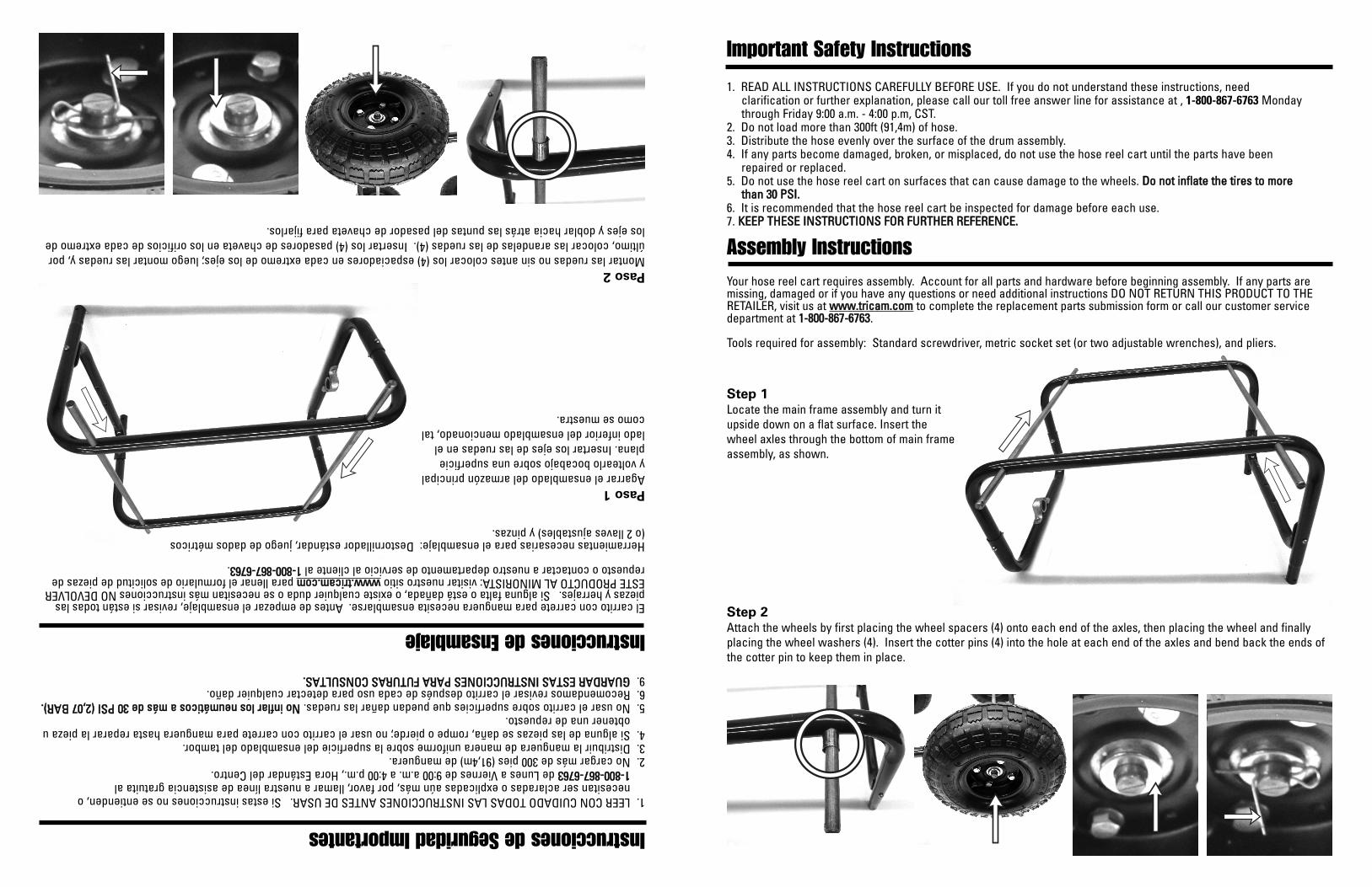
Paso 1Agarrar el ensamblado del armazón principaly voltearlo bocabajo sobre una superficieplana. Insertar los ejes de las ruedas en ellado inferior del ensamblado mencionado, talcomo se muestra.
Paso 2Montar las ruedas no sin antes colocar los (4) espaciadores en cada extremo de los ejes; luego montar las ruedas y, porúltimo, colocar las arandelas de las ruedas (4). Insertar los (4) pasadores de chaveta en los orificios de cada extremo delos ejes y doblar hacia atrás las puntas del pasador de chaveta para fijarlos.
1. READ ALL INSTRUCTIONS CAREFULLY BEFORE USE. If you do not understand these instructions, needclarification or further explanation, please call our toll free answer line for assistance at , 1-800-867-6763 Mondaythrough Friday 9:00 a.m. - 4:00 p.m, CST.
2. Do not load more than 300ft (91,4m) of hose.3. Distribute the hose evenly over the surface of the drum assembly.4. If any parts become damaged, broken, or misplaced, do not use the hose reel cart until the parts have been
repaired or replaced.5. Do not use the hose reel cart on surfaces that can cause damage to the wheels. DDoo nnoott iinnffllaattee tthhee ttiirreess ttoo mmoorree
tthhaann 3300 PPSSII..6. It is recommended that the hose reel cart be inspected for damage before each use.7. KKEEEEPP TTHHEESSEE IINNSSTTRRUUCCTTIIOONNSS FFOORR FFUURRTTHHEERR RREEFFEERREENNCCEE..
Your hose reel cart requires assembly. Account for all parts and hardware before beginning assembly. If any parts aremissing, damaged or if you have any questions or need additional instructions DO NOT RETURN THIS PRODUCT TO THERETAILER, visit us at wwwwww..ttrriiccaamm..ccoomm to complete the replacement parts submission form or call our customer servicedepartment at 11--880000--886677--66776633.
Tools required for assembly: Standard screwdriver, metric socket set (or two adjustable wrenches), and pliers.
Important Safety Instructions
Assembly Instructions
Step 1Locate the main frame assembly and turn itupside down on a flat surface. Insert thewheel axles through the bottom of main frameassembly, as shown.
Step 2Attach the wheels by first placing the wheel spacers (4) onto each end of the axles, then placing the wheel and finallyplacing the wheel washers (4). Insert the cotter pins (4) into the hole at each end of the axles and bend back the ends ofthe cotter pin to keep them in place.
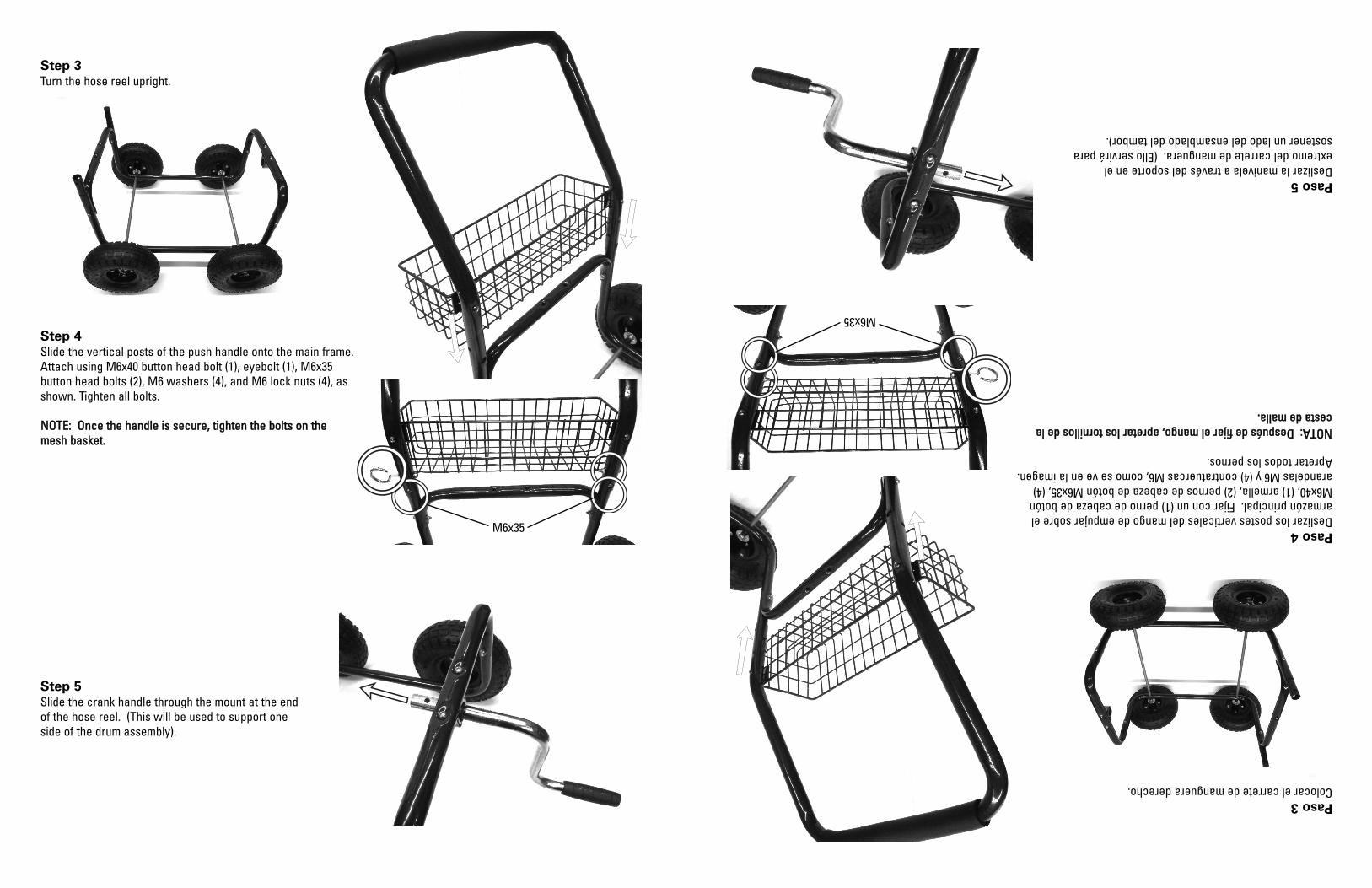
Step 4Slide the vertical posts of the push handle onto the main frame.Attach using M6x40 button head bolt (1), eyebolt (1), M6x35button head bolts (2), M6 washers (4), and M6 lock nuts (4), asshown. Tighten all bolts.
NNOOTTEE:: OOnnccee tthhee hhaannddllee iiss sseeccuurree,, ttiigghhtteenn tthhee bboollttss oonn tthheemmeesshh bbaasskkeett..
Step 3Turn the hose reel upright.
Step 5Slide the crank handle through the mount at the endof the hose reel. (This will be used to support oneside of the drum assembly).
Paso 4Deslizar los postes verticales del mango de empujar sobre elarmazón principal. Fijar con un (1) perno de cabeza de botónM6x40, (1) armella, (2) pernos de cabeza de botón M6x35, (4)arandelas M6 y (4) contratuercas M6, como se ve en la imagen.Apretar todos los pernos.
NNOOTTAA:: DDeessppuuééss ddee ffiijjaarr eell mmaannggoo,, aapprreettaarr llooss ttoorrnniillllooss ddee llaacceessttaa ddee mmaallllaa..
Paso 3Colocar el carrete de manguera derecho.
Paso 5Deslizar la manivela a través del soporte en elextremo del carrete de manguera. (Ello servirá parasostener un lado del ensamblado del tambor).
M6x35
M6x35
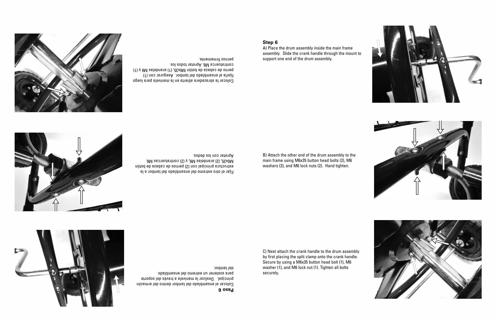
Paso 6Colocar el ensamblado del tambor dentro del armazónprincipal. Deslizar la manivela a través del soportepara sostener un extremo del ensamblado del tambor.
Fijar el otro extremo del ensamblado del tambor a laestructura principal con (2) pernos de cabeza de botónM6x35, (2) arandelas M6, y (2) contratuercas M6.Apretar con los dedos.
Colocar la abrazadera abierta en la manivela para luegofijarla al ensamblado del tambor. Asegurar con (1)perno de cabeza de botón M6x35, (1) arandelas M6 y (1)contratuerca M6. Apretar todos los pernos firmemente.
Step 6A) Place the drum assembly inside the main frameassembly. Slide the crank handle through the mount tosupport one end of the drum assembly.
B) Attach the other end of the drum assembly to themain frame using M6x35 button head bolts (2), M6washers (2), and M6 lock nuts (2). Hand tighten.
C) Next attach the crank handle to the drum assemblyby first placing the split clamp onto the crank handle.Secure by using a M6x35 button head bolt (1), M6washer (1), and M6 lock nut (1). Tighten all boltssecurely.
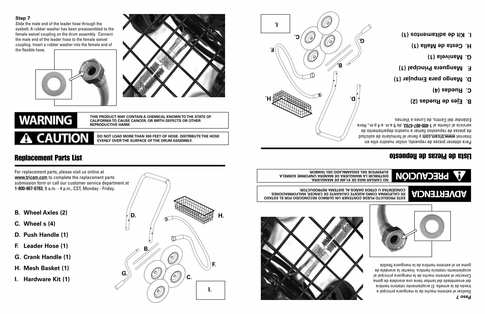
Replacement Parts List
For replacement parts, please visit us online atwwwwww..ttrriiccaamm..ccoomm to complete the replacement partssubmission form or call our customer service department at11--880000--886677--66776633, 9 a.m. - 4 p.m., CST, Monday - Friday.
H.B. Wheel Axles (2)
C. Wheel s (4)
D. Push Handle (1)
F. Leader Hose (1)
G. Crank Handle (1)
H. Mesh Basket (1)
I. Hardware Kit (1)
B.
D.
C.G.
F.
Step 7Slide the male end of the leader hose through theeyebolt. A rubber washer has been preassembled to thefemale swivel coupling on the drum assembly. Connectthe male end of the leader hose to the female swivelcoupling. Insert a rubber washer into the female end ofthe flexible hose.
DO NOT LOAD MORE THAN 300 FEET OF HOSE. DISTRIBUTE THE HOSE
EVENLY OVER THE SURFACE OF THE DRUM ASSEMBLY.CAUTION
THIS PRODUCT MAY CONTAIN A CHEMICAL KNOWN TO THE STATE OFCALIFORNIA TO CAUSE CANCER, OR BIRTH DEFECTS OR OTHERREPRODUCTIVE HARM.WARNING
I.
Lista de Piezas de Repuesto
Para obtener piezas de repuesto, visitar nuestro sitio enInternet wwwwww..ttrriiccaamm..ccoommy llenar el formulario de solicitudde piezas de repuestoo llamar a nuestro departamento deservicio al cliente al 11--880000--886677--66776633, de 9 a.m. a 4 p.m., HoraEstándar del Centro, de Lunes a Viernes.
H.B.Ejes de Ruedas (2)
C.Ruedas (4)
D.Mango para Empujar (1)
F.Manguera Principal (1)
G.Manivela (1)
H.Cesta de Malla (1)
I.Kit de aditamentos (1)
B.
D.
C.G.
F.
Paso 7Deslizar el extremo macho de la manguera principal através de la armella. El acoplamiento rotatorio hembradel ensamblado del tambor tiene una arandela de goma.Conectar el extremo macho de la manguera principal alacoplamiento rotatorio hembra. Insertar la arandela degoma en el extremo hembra de la manguera flexible
NO CARGAR MÁS DE 91,4M DE MANGUERA.DISTRIBUIR LA MANGUERA DE MANERA UNIFORME SOBRELASUPERFICIE DEL ENSAMBLADO DEL TAMBOR. PRECAUCIÓN
ESTE PRODUCTO PUEDE CONTENER UN QUÍMICO RECONOCIDO POR EL ESTADODE CALIFORNIA COMO AGENTE CAUSANTE DE CÁNCER,MALFORMACIONESCONGÉNITAS U OTROS DAÑOS AL SISTEMA REPRODUCTOR. ADVERTENCIA
I.