homework #3 digital logic design
TRANSCRIPT

Homework #3 – Digital Logic Design UPDATE 6/3: Changed name of output pin in Q1b to work with Logisim Evolution. Tester updated! If you’ve
already forked the assignment, see the Piazza post on updating your local tester!
UPDATE 6/3 #2: Renamed the adder circuit to “my_adder”, as Logisim Evolution enforces naming rules on
filenames as well.
Due date: see course website
Directions:
For short-answer questions, submit your answers in PDF format to GradeScope assignment “Homework 3
written”.
o Please type your solutions. If hand-written material must be included, ensure it is photographed or
scanned at high quality and oriented properly so it appears right-side-up.
o Please include your name on submitted work.
For Logisim questions, submit .circ files via GitLab or direct upload to GradeScope assignment “Homework 3
code”:
o Circuits will be tested using an automated system, so you must name the input/output pins
exactly as described, and submit using the specified filename!
o You may only use the basic gates (NOT, AND, OR, NAND, NOR, XOR), D flip-flops, multiplexers,
splitters, tunnels, and clocks. Everything else you must construct from these.
Start by cloning the “homework3” git repo, similar to past assignments.
A Logisim Evolution circuit self-tester has been provided. It works much the same as previous self-test tools;
you just need to have your .circ files in the directory with the tester. The tester is known to work in the Duke
Linux environment, but may possibly work elsewhere. Additional info on the tester is included in three
appendices at the end of this document. There are a few things that need to be done for the tester to work
correctly:
o Name the files and label the pins as per the directions given. The self-tester will NOT WORK with
different names or labels.
o For the FSM question, use the clock available in Logisim Evolution to run the DFFs.
o Additionally, to run the self-tester you will have to place the Logisim Evolution files in the same
folder as the python script, the jar file and the folder labelled tests.
o You can use the command ./tester.py in the following manner:
./tester.py <arguments>
The following arguments can be used with that command:
- ALL: Runs all the tests
- CLEAN: Removes all saved test outputs
- circuit1a: Runs tests for circuit1a.circ
- circuit1c: Runs tests for circuit1c.circ
- my_adder: Runs tests for my_adder.circ
- plastic: Runs tests for plastic.circ
o Lastly, remember that the tests cases provided are not exhaustive so testing more cases manually
would be recommended.
You must do all work individually, and you must submit your work electronically via GradeScope.
o All submitted circuits will be tested for suspicious similarities to other circuits, and the test will
uncover cheating, even if it is “hidden.”
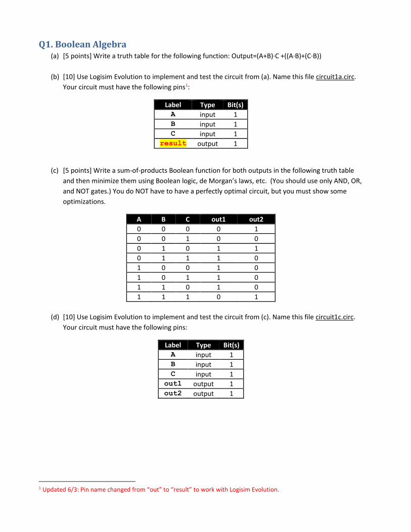
Q1. Boolean Algebra (a) [5 points] Write a truth table for the following function: Output=(A+B)∙C +((A∙B)+(C∙B))
(b) [10] Use Logisim Evolution to implement and test the circuit from (a). Name this file circuit1a.circ.
Your circuit must have the following pins1:
Label Type Bit(s) A input 1 B input 1 C input 1
result output 1
(c) [5 points] Write a sum-of-products Boolean function for both outputs in the following truth table
and then minimize them using Boolean logic, de Morgan’s laws, etc. (You should use only AND, OR,
and NOT gates.) You do NOT have to have a perfectly optimal circuit, but you must show some
optimizations.
A B C out1 out2
0 0 0 0 1
0 0 1 0 0
0 1 0 1 1
0 1 1 1 0
1 0 0 1 0
1 0 1 1 0
1 1 0 1 0
1 1 1 0 1
(d) [10] Use Logisim Evolution to implement and test the circuit from (c). Name this file circuit1c.circ.
Your circuit must have the following pins:
Label Type Bit(s) A input 1 B input 1 C input 1
out1 output 1 out2 output 1
1 Updated 6/3: Pin name changed from “out” to “result” to work with Logisim Evolution.
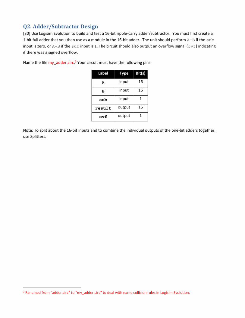
Q2. Adder/Subtractor Design [30] Use Logisim Evolution to build and test a 16-bit ripple-carry adder/subtractor. You must first create a
1-bit full adder that you then use as a module in the 16-bit adder. The unit should perform A+B if the sub
input is zero, or A-B if the sub input is 1. The circuit should also output an overflow signal (ovf) indicating
if there was a signed overflow.
Name the file my_adder.circ.2 Your circuit must have the following pins:
Label Type Bit(s)
A input 16
B input 16
sub input 1
result output 16
ovf output 1
Note: To split about the 16-bit inputs and to combine the individual outputs of the one-bit adders together,
use Splitters.
2 Renamed from “adder.circ” to “my_adder.circ” to deal with name collision rules in Logisim Evolution.

Q3. Finite State Machines You’re an engineer at a plastics factory, and you’ve been asked to automate
an old manually-driven injection molding machine. Design a finite state
machine (FSM) for this purpose.
Your finite state machine will have two3 inputs: a human interface button to
start the process (“go”, a boolean), and a temperature sensor that indicates
when the machine is hot enough to inject plastic (“temp_ok”, boolean).
It has two outputs: a heater coil (“heater”) used to raise the temperature
and an extruder motor that actually injects the plastic (“extruder”).
The rules governing this system are as follows:
1. When the system is first turned on, it’s idle. Both the heater and
extruder are off.
o In this situation, the “temp_ok” signal is irrelevant.
o If “go” is pressed, the system heats up as described in #2 below.
o Otherwise, remain in this state.
2. When heating up, the heater is on but the extruder is off.
o During the heat up process, if “go” is pressed again, there should be no effect.
o Once “temp_ok” signal is received, the system should stop heating; it is now ready to
inject (see #3 below).
o Otherwise, remain in this state.
3. When ready to inject, the heater and extruder are both off.
o While in this state, if “temp_ok” becomes false (i.e., the system cools off too much), it
should revert to the heating up mode above (#2) regardless of the state of the go input.
o While in this state, if “go” is pressed, it should perform an extrusion (#4 below).
o Otherwise, remain in this state.
4. While performing an extrusion, the heater is off and the extruder is on.
o This state lasts just one cycle.
o The use of the “go” button in this state is irrelevant.
o If “temp_ok” is false, the system should proceed to the heating up stage (#2).
o If “temp_ok” is true, the system should proceed to the ready to inject stage (#3).
You won’t have to worry about turning off or resetting the system – a separate power cutoff will be used
for that.
3 Fixed 6/7/2021. This used to say “three”.

For full credit, you must use the systematic design methodology we covered in class:
(a) [10] Draw a state transition diagram, where each state has a unique identifier that is a string of bits
(e.g., states 00, 01, etc.) as well as the associated value for outputs heater and extruder. Label
all of the arcs between transitions with the inputs go and temp_ok that cause those transitions.
(b) [10] Draw a truth table for the state transition diagram. From a truth table perspective, the inputs
are go, temp_ok and the current state bits (Q0, Q1, etc.); the outputs are heater, extruder,
and the next state bits (D0, D1, etc.).
(c) [30] Use Logisim Evolution to implement and test this circuit. Name this file plastic.circ. Your circuit
must have the following pins:
Label Type Bit(s)
go input 1
temp_ok input 1
heater output 1
extruder output 1
Tips:
Implement your FSM as a “Moore” machine, meaning that the output should depend exclusively on
the current state. In other words, your output should be written on the state nodes in the state
transition diagram rather than on the edges. When writing the truth table for this, the heater and
extruder columns should be based just on the current state columns.
Run a “Clock” component to all the clock inputs in the DFFs.
A compliant circuit will look something like this:

Appendix: Getting the tester to work locally The tester will work out-of-box on the login.oit.duke.edu environment (if run as “python tester.py”) and the
Docker environment.
However, if you want to test locally, you need the right version of Java set up and in your PATH. Note:
support for this is best-effort; if you have trouble we can’t resolve, you have the above two environments.
For Windows (with Ubuntu in Windows Service for Linux) or Ubuntu Linux
We just need to install Java Runtime Environment 1.8, then update our config to use that Java by default.
This will only effect your Linux-on-Windows environment.
sudo apt-get install -y openjdk-8-jre
sudo update-alternatives --config java
After the second command, you’ll be asked to pick a Java. By number, choose
“/usr/lib/jvm/java-8-openjdk-amd64/jre/bin/java”.
You may get one spurious fail from the tester after initial setup, as the first time run it will print a little
message. Subsequent tests runs should function normally.
For Mac
Mac machines tend to have a few different Javas lying around, and the tester does its best to find a suitable
one. In the assignment directory, try:
java -jar logisim_ev_cli.jar
If you see “error: specify logisim file to open”, you’re good to go. If you see some big ugly
crash, you probably need to switch Java versions. You likely have the required version on your system by
virtue of having installed Logisim Evolution. Java 1.8.0 is known to work. Try following these directions to
switch Java versions. If you overcome a Java issue and get it working, document how and post to Piazza; I’ll
update these directions.

Appendix: Tester info The test system for Logisim Evolution assignments uses the same front-end tool as earlier assignments, but
to have it control Logisim Evolution, a special command-line variant of Logisim Evolution is packaged with
it. When you use the tester, it runs this with your circuit and a number of command-line options that tell it
how to set the inputs to your circuit and how to print the outputs.
You can review the tests details by looking inside settings.json. If you see a line like this for circuit1a:
{ "desc": "A=0x9BDF, B=0x8ACE, sub=0",
"args": ["-c", "0", "-ip", "A=0x9BDF,B=0x8ACE,sub=0", "-of", "h"] },
Then it will run this:
java -jar logisim_ev_cli.jar -f adder.circ -c 0 -ip A=0x9BDF,B=0x8ACE,sub=0 -of h
The options run the circuit for 0 cycles (as it has no clock so there’s no need to run it over time), set pins A
and B to the given hex values and sub to zero, and set the output format to hex. The output will look like:
0 out ovf 0x01
0 out result 0x26ad
The fields are cycle number, the type of output (“out”, “probe”, or a few others), the name of the pin (“ovf”
and “result” here), then the value at that time. For sequential circuits, output is shown per clock cycle, such
as this example for the finite state machine:
0 out extruder 0
0 out heater 0
1re out extruder 0
1re out heater 0
2re out extruder 0
2re out heater 0
3re out extruder 0
3re out heater 0
4re out extruder 0
4re out heater 0
5re out extruder 0
5re out heater 0
Using this information, you can interpret the actual and expected files (and the resulting diff).

Appendix: Plastic test case details Because the test cases for plastic are a bit long and the command line option format is somewhat cryptic,
here’s a nicer presentation of them.
Test cases 0-3 simply apply constant values to the inputs – these are shown in the test description.
Test cases 4-8 apply changing values to the inputs to try to put the finite state machine through its paces.
Test case 9 is long and randomly generated.
The tables below show these cases. Here, “#” is the cycle in which the input is changed.
Test 4
# go temp_ok
2 0 0
4 1 0
6 0 1
8 1 1
10 0 0
Test 5
# go temp_ok
2 0 0
3 1 0
4 0 1
5 1 1
6 0 0
Test 6
# go temp_ok
2 1 0
3 0 0
4 0 1
5 1 0
6 0 0
Test 7
# go temp_ok
2 1 1
3 0 1
4 1 1
5 0 1
6 1 0
Test 8
# go temp_ok
2 1 1
3 0 1
4 1 1
5 0 1
6 1 1

Test 9 # go temp_ok
2 0 1 3 0 1 4 1 0 5 1 0 6 1 0 7 1 1 8 1 1 9 1 0
10 1 1 11 1 1 12 0 1 13 0 0 14 0 0 15 1 1 16 0 1 17 1 1 18 1 1 19 1 1 20 0 0 21 1 1 22 1 1 23 0 1 24 1 1 25 1 1 26 0 0 27 0 0 28 1 0 29 1 0 30 0 0 31 1 1 32 1 1 33 1 1 34 1 1 35 1 1 36 0 1 37 0 0 38 1 1 39 1 0 40 0 1 41 1 0 42 0 1 43 0 1 44 0 1 45 0 1 46 0 0 47 1 0 48 1 0 49 1 1 50 1 0 51 0 1 52 1 1 53 0 1 54 0 0 55 1 1 56 0 0 57 1 1 58 1 0 59 1 0 60 1 0 61 1 1 62 1 0 63 1 1 64 0 0 65 0 1 66 0 0 67 0 1

68 0 1 69 0 1 70 1 1 71 0 1 72 0 0 73 0 1 74 1 1 75 0 1 76 0 1 77 0 0 78 0 1 79 0 0 80 0 1 81 0 0 82 1 0 83 1 0 84 0 1 85 1 0 86 1 0 87 1 1 88 1 0 89 0 1 90 0 0 91 0 1 92 1 1 93 1 0 94 1 1 95 0 1 96 1 1 97 1 0 98 1 1 99 0 1
100 1 0 101 1 1