hn system - hughesnetcustomer.kb.hughesnet.com/documents/1037087-0001_b.pdf · 1037087-0001...
TRANSCRIPT
1037087-0001Revision BOctober 19, 2006
HN System
Installation Manual for .74 m Ku-band Upgradeable Antenna Model AN6-074P

Copyright © 2006 Hughes Network Systems, LLC
All rights reserved. This publication and its contents are proprietary to Hughes Network Systems, LLC. No part of this publication may be reproduced in any form or by any means without the written permission of Hughes Network Systems, LLC, 11717 Exploration Lane, Germantown, Maryland 20876.
Hughes Network Systems, LLC has made every effort to ensure the correctness and completeness of the material in this document. Hughes Network Systems, LLC shall not be liable for errors contained herein. The information in this document is subject to change without notice. Hughes Network Systems, LLC makes no warranty of any kind with regard to this material, including, but not limited to, the implied warranties of merchantability and fitness for a particular purpose.
Trademarks
Hughes, Hughes Network Systems, and HughesNet are trademarks of Hughes Network Systems, LLC. All other trademarks are the property of their respective owners.

Important safety informationFor your safety and protection, read this entire installation manual before you attempt to install the satellite antenna. In particular, read this safety section carefully. Keep this safety information where you can refer to it if necessary.
Types of warnings used in this manual
This section introduces the various types of warnings used in this manual to alert you to possible safety hazards.
DANGER
Indicates an imminently hazardous situation, which, if not avoided, will result in death or serious injury.
WARNING
Indicates a potentially hazardous situation, which, if not avoided, could result in death or serious injury.
CAUTION
Indicates a potentially hazardous situation, which, if not avoided, may result in minor or moderate injury.
CAUTIONIndicates a situation or practice that might result in property damage.
• Important safety information 1037087-0001 Revision B iii

iv
Product warning labels The following safety alert labels are affixed to the satellite antenna feed support arm, transmitter, and antenna reflector:
These labels advise that the antenna emits radio frequency (RF) energy. Because of this potential safety hazard, observe all cautions on these labels and in the following section (Antenna installation safety) concerning RF radiation.
Feed support arm
Reflector (back side)
Transmitter
Safety alert labels on the antenna assembly
• Important safety information 1037087-0001 Revision B

Antenna installation safety
Observe the following precautions when installing the satellite antenna. This manual also includes additional safety alerts where appropriate concerning specific installation procedures.
WARNINGOnly Hughes-certified installers may install or service Hughes earth stations and components. Installers must expressly acknowledge the Hughes requirements for Hughes installations.
DANGERIf you work on a roof, tower, or other high structure or use a ladder or scaffold to access the work site, follow these precautions to prevent personal injury or death:
• Walk only on sound roof structures. • Make sure the antenna assembly and installation
surface are structurally sound so they can support all loads (equipment weight, ice, and wind).
• Use appropriate safety equipment (for example, a lifeline), depending on the work location.
• Follow all safety precautions from the manufacturers of all safety equipment and other equipment used.
• Perform as many procedures as possible on the ground.
DANGER• To avoid electric shock, stay at least 20 ft from power
lines. • If any part of the antenna or mount assembly comes in
contact with a power line, call your local power company to remove it. Do not try to remove it yourself.
Failure to heed these warnings could result in serious injury or death.
• Important safety information 1037087-0001 Revision B v

vi
WARNING• Do not work in high wind or rain or if a storm, lightning,
or other adverse weather conditions are present or approaching.
• Do not attempt to assemble, move, or mount the antenna on a windy day. Even a slight wind can unexpectedly create strong, unexpected forces on the antenna surface.
• Important safety information 1037087-0001 Revision B

CAUTIONObserve these precautions to avoid exposure to RF radiation, a potential safety hazard:
• The antenna must be installed in a location or manner not readily accessible to children and in a manner that prevents human exposure to potentially harmful levels of radiation.
• Antennas mounted in Puerto Rico, the continental United States, or at any site with greater than a 30° elevation angle must be installed such that the lower lip of the antenna reflector is at least 5 ft above any surface upon which a person might be expected to stand, and 3 ft 3 inches from any opening (such as a door or window) in a building or adjacent structure.
• Antennas mounted in Canada, Alaska, Hawaii, or any site with less than a 30° elevation must be installed such that the lower lip of the antenna reflector is at least 5 ft 9 inches above any surface upon which a person might be expected to stand, and 3 ft 3 inches from any opening (such as a door or window) in a building or adjacent structure.
• The antenna must be mounted such that no object which could reasonably be expected to support a person is within 6 ft 7 inches of the edges of a cylindrical space projecting outward from the antenna reflector toward the satellite.
• If the above distance requirements cannot be met, the antenna must be mounted in a controlled area inaccessible to the general public, such as a fenced enclosure or a roof.
• The antenna must be mounted such that there is no object outside the controlled area which could reasonably be expected to support a person within 6 ft 7 inches of the edges of a cylindrical space projecting outward from the antenna reflector toward the satellite.
• A fenced installation must have a locked entry, and the fenced area must be large enough to protect the general public from exposure to potentially harmful levels of radiation.
• Access to a roof installation in a commercial, industrial, or institutional environment must be limited by a door or a permanently fastened ladder that is locked to deny access to the general public.
Failure to observe these cautions could result in injury to eyes or other personal injury.
• Important safety information 1037087-0001 Revision B vii

viii
Some installations may require additional precautions. See also the HN System Antenna Site Preparation and Mount Installation Guide (1035678-0001).
CAUTION
• All installations of any type or size must carry an industry standard and government approved Radiation Hazard Caution label on the feed arm.
• A fenced or roof installation in a commercial, industrial, or institutional environment must carry a Radiation Hazard Caution sign on the access door, gate, or permanently mounted access ladder that is within plain sight of anyone approaching the antenna from the front or sides of the reflector.
Failure to observe these cautions could result in injury to eyes or other personal injury.
• Important safety information 1037087-0001 Revision B
Contents
Important safety information . . . . . . . . . . . . . . . . . . . . . iiiTypes of warnings used in this manual . . . . . . . . . . . . . . . . . . . iiiProduct warning labels . . . . . . . . . . . . . . . . . . . . . . . . . . . . . . . . ivAntenna installation safety . . . . . . . . . . . . . . . . . . . . . . . . . . . . . .v
About this document . . . . . . . . . . . . . . . . . . . . . . . . . . xviiScope and audience . . . . . . . . . . . . . . . . . . . . . . . . . . . . . . . . .xviiOrganization . . . . . . . . . . . . . . . . . . . . . . . . . . . . . . . . . . . . . . .xviiRevision record. . . . . . . . . . . . . . . . . . . . . . . . . . . . . . . . . . . . .xvii
Chapter 1Overview . . . . . . . . . . . . . . . . . . . . . . . . . . . . . . . . . . . . . . .1The model AN6-074P antenna . . . . . . . . . . . . . . . . . . . . . . . . . . .2Antenna installation summary . . . . . . . . . . . . . . . . . . . . . . . . . . .3Tasks related to antenna installation . . . . . . . . . . . . . . . . . . . . . .4
Selecting the installation site . . . . . . . . . . . . . . . . . . . . . . . . . .4Installing the antenna mount . . . . . . . . . . . . . . . . . . . . . . . . . .4Installing the IDU. . . . . . . . . . . . . . . . . . . . . . . . . . . . . . . . . . .4Grounding. . . . . . . . . . . . . . . . . . . . . . . . . . . . . . . . . . . . . . . . .4Approved cables . . . . . . . . . . . . . . . . . . . . . . . . . . . . . . . . . . . .5
Chapter 2Antenna parts and required tools. . . . . . . . . . . . . . . . . . .7Antenna kit components . . . . . . . . . . . . . . . . . . . . . . . . . . . . . . . .7
Vertical shim kit (if required). . . . . . . . . . . . . . . . . . . . . . . . . .8Az/El mount assembly . . . . . . . . . . . . . . . . . . . . . . . . . . . . . . .8Antenna reflector . . . . . . . . . . . . . . . . . . . . . . . . . . . . . . . . . . .9Reflector bracket and polarization plate. . . . . . . . . . . . . . . . . .9Tailpiece . . . . . . . . . . . . . . . . . . . . . . . . . . . . . . . . . . . . . . . . .10Feed support arm . . . . . . . . . . . . . . . . . . . . . . . . . . . . . . . . . .10Feed horn . . . . . . . . . . . . . . . . . . . . . . . . . . . . . . . . . . . . . . . .10Related components . . . . . . . . . . . . . . . . . . . . . . . . . . . . . . . .11
Radio assembly. . . . . . . . . . . . . . . . . . . . . . . . . . . . . . . . . .11Trimast (or other antenna mount). . . . . . . . . . . . . . . . . . . .11
Small hardware parts list . . . . . . . . . . . . . . . . . . . . . . . . . . . . . .12Tools . . . . . . . . . . . . . . . . . . . . . . . . . . . . . . . . . . . . . . . . . . . . . .13
• Contents 1037087-0001 Revision B ix

x
Chapter 3Installing the antenna and radio assembly . . . . . . . . . .15Determining the pointing values . . . . . . . . . . . . . . . . . . . . . . . .16General instructions for assembling the antenna . . . . . . . . . . . .17Installing a shim for vertical transmit polarization . . . . . . . . . .18Installing the Az/El mount onto the mast pipe . . . . . . . . . . . . . .22Installing the antenna reflector . . . . . . . . . . . . . . . . . . . . . . . . . .23Installing the feed support arm. . . . . . . . . . . . . . . . . . . . . . . . . .25
Installing the tailpiece. . . . . . . . . . . . . . . . . . . . . . . . . . . . . . .25Inserting and attaching the feed support arm . . . . . . . . . . . . .27
Installing the radio assembly . . . . . . . . . . . . . . . . . . . . . . . . . . .28
Chapter 4Cabling and connections . . . . . . . . . . . . . . . . . . . . . . . . .31Previous cabling work . . . . . . . . . . . . . . . . . . . . . . . . . . . . . . . .31Routing the cables at the ODU. . . . . . . . . . . . . . . . . . . . . . . . . .32Connecting the transmit and receive cables . . . . . . . . . . . . . . . .33
Transmit cable . . . . . . . . . . . . . . . . . . . . . . . . . . . . . . . . . . . .33Receive cable . . . . . . . . . . . . . . . . . . . . . . . . . . . . . . . . . . . . .34
Ground connection . . . . . . . . . . . . . . . . . . . . . . . . . . . . . . . . . . .35
Chapter 5Pointing the antenna . . . . . . . . . . . . . . . . . . . . . . . . . . . .37Antenna pointing overview . . . . . . . . . . . . . . . . . . . . . . . . . . . .38
Using the installation software . . . . . . . . . . . . . . . . . . . . . . . .38Peaking the signal. . . . . . . . . . . . . . . . . . . . . . . . . . . . . . . . . .38Personnel requirements . . . . . . . . . . . . . . . . . . . . . . . . . . . . .39Pointing parameters . . . . . . . . . . . . . . . . . . . . . . . . . . . . . . . .39
Prerequisites for antenna pointing . . . . . . . . . . . . . . . . . . . . . . .39Outdoor pointing interface . . . . . . . . . . . . . . . . . . . . . . . . . . . . .39
Installing the OPI . . . . . . . . . . . . . . . . . . . . . . . . . . . . . . . . . .40OPI block . . . . . . . . . . . . . . . . . . . . . . . . . . . . . . . . . . . . . .40
Adjusting the antenna. . . . . . . . . . . . . . . . . . . . . . . . . . . . . . . . .41Adjustment locations on the antenna . . . . . . . . . . . . . . . . . . .42
Setting coarse elevation . . . . . . . . . . . . . . . . . . . . . . . . . . . . . . .43Fine elevation pointing tool . . . . . . . . . . . . . . . . . . . . . . . . . . . .44
Installing the pointing tool . . . . . . . . . . . . . . . . . . . . . . . . . . .44Fine elevation adjustment. . . . . . . . . . . . . . . . . . . . . . . . . . . .45
Receive pointing. . . . . . . . . . . . . . . . . . . . . . . . . . . . . . . . . . . . .46Initial elevation setting . . . . . . . . . . . . . . . . . . . . . . . . . . . . . .46Setting polarization. . . . . . . . . . . . . . . . . . . . . . . . . . . . . . . . .46Setting azimuth. . . . . . . . . . . . . . . . . . . . . . . . . . . . . . . . . . . .47Peaking the signal (procedure) . . . . . . . . . . . . . . . . . . . . . . . .49
• Contents 1037087-0001 Revision B

Isolating the transmit signal . . . . . . . . . . . . . . . . . . . . . . . . . . . .50Manual ACP test. . . . . . . . . . . . . . . . . . . . . . . . . . . . . . . . . . .50Automatic ACP test . . . . . . . . . . . . . . . . . . . . . . . . . . . . . . . .51
Final steps. . . . . . . . . . . . . . . . . . . . . . . . . . . . . . . . . . . . . . . . . .52Remove the OPI and fine elevation pointing tool . . . . . . . . .52Check for safety labels and signs . . . . . . . . . . . . . . . . . . . . . .52Subsequent steps. . . . . . . . . . . . . . . . . . . . . . . . . . . . . . . . . . .52
Acronyms and abbreviations . . . . . . . . . . . . . . . . . . . . .53Index . . . . . . . . . . . . . . . . . . . . . . . . . . . . . . . . . . . . . . . . .55
• Contents 1037087-0001 Revision B xi

xii
• Contents 1037087-0001 Revision B
Figures
Chapter 11. The Hughes model AN6-074P .74 m satellite antenna . . . . . . . . . . . . . . . . . . . .2
Chapter 22. Shim for vertical transmit polarization . . . . . . . . . . . . . . . . . . . . . . . . . . . . . . . . .83. Az/El mount assembly . . . . . . . . . . . . . . . . . . . . . . . . . . . . . . . . . . . . . . . . . . . . .84. Antenna reflector . . . . . . . . . . . . . . . . . . . . . . . . . . . . . . . . . . . . . . . . . . . . . . . . .95. Reflector bracket and polarization plate . . . . . . . . . . . . . . . . . . . . . . . . . . . . . . . .96. Tailpiece . . . . . . . . . . . . . . . . . . . . . . . . . . . . . . . . . . . . . . . . . . . . . . . . . . . . . . .107. Feed support arm . . . . . . . . . . . . . . . . . . . . . . . . . . . . . . . . . . . . . . . . . . . . . . . .108. Feed horn . . . . . . . . . . . . . . . . . . . . . . . . . . . . . . . . . . . . . . . . . . . . . . . . . . . . . .109. Radio assembly. . . . . . . . . . . . . . . . . . . . . . . . . . . . . . . . . . . . . . . . . . . . . . . . . .11
10. Trimast in various configurations. . . . . . . . . . . . . . . . . . . . . . . . . . . . . . . . . . . .11
Chapter 311. Shim location next to TRIA . . . . . . . . . . . . . . . . . . . . . . . . . . . . . . . . . . . . . . . .1812. Horizontal shim and vertical shim for transmit polarization . . . . . . . . . . . . . . .1913. Direction of TRIA rotation for vertical polarization . . . . . . . . . . . . . . . . . . . . .2014. TRIA position for horizontal and vertical transmit polarization . . . . . . . . . . . .2115. Making sure the mast is level . . . . . . . . . . . . . . . . . . . . . . . . . . . . . . . . . . . . . . .2216. Installing the Az/El mount assembly . . . . . . . . . . . . . . . . . . . . . . . . . . . . . . . . .2217. Attaching the reflector bracket and polarization plate . . . . . . . . . . . . . . . . . . . .2318. Polarization scale . . . . . . . . . . . . . . . . . . . . . . . . . . . . . . . . . . . . . . . . . . . . . . . .2419. Attaching the antenna reflector. . . . . . . . . . . . . . . . . . . . . . . . . . . . . . . . . . . . . .2420. Inserting the tailpiece into the reflector bracket . . . . . . . . . . . . . . . . . . . . . . . . .2521. Inserting the tailpiece bolts. . . . . . . . . . . . . . . . . . . . . . . . . . . . . . . . . . . . . . . . .2622. Attaching the feed support arm to the tailpiece . . . . . . . . . . . . . . . . . . . . . . . . .2723. Installing the feed horn . . . . . . . . . . . . . . . . . . . . . . . . . . . . . . . . . . . . . . . . . . . .2824. Installing the radio assembly . . . . . . . . . . . . . . . . . . . . . . . . . . . . . . . . . . . . . . .2925. Assembled antenna . . . . . . . . . . . . . . . . . . . . . . . . . . . . . . . . . . . . . . . . . . . . . . .30
Chapter 426. Transmit and receive cable configurations . . . . . . . . . . . . . . . . . . . . . . . . . . . . .3227. Transmit connector (arrow) – female F connector . . . . . . . . . . . . . . . . . . . . . . .3328. Receive connector (arrow) – female F connector. . . . . . . . . . . . . . . . . . . . . . . .3429. Ground screw on the transmitter (arrow) . . . . . . . . . . . . . . . . . . . . . . . . . . . . . .35
• Figures 1037087-0001 Revision B xiii

xiv
Chapter 530. OPI (optional pointing tool) . . . . . . . . . . . . . . . . . . . . . . . . . . . . . . . . . . . . . . . .3931. Installing the OPI . . . . . . . . . . . . . . . . . . . . . . . . . . . . . . . . . . . . . . . . . . . . . . . .4032. Adjusting azimuth, elevation, and polarization . . . . . . . . . . . . . . . . . . . . . . . . .4133. Pointing adjustments on the antenna—azimuth, elevation, and polarization. . .4234. Setting coarse elevation . . . . . . . . . . . . . . . . . . . . . . . . . . . . . . . . . . . . . . . . . . .4335. Installing the fine elevation pointing tool. . . . . . . . . . . . . . . . . . . . . . . . . . . . . .4436. Elevation adjustments on the antenna . . . . . . . . . . . . . . . . . . . . . . . . . . . . . . . .4537. Polarization adjustments on the antenna . . . . . . . . . . . . . . . . . . . . . . . . . . . . . .4638. Azimuth adjustments on the antenna . . . . . . . . . . . . . . . . . . . . . . . . . . . . . . . . .47
• Figures 1037087-0001 Revision B

Tables
Chapter 21. Small hardware parts . . . . . . . . . . . . . . . . . . . . . . . . . . . . . . . . . . . . . . . . . . . . .122. Tools required to install and point the antenna. . . . . . . . . . . . . . . . . . . . . . . . . .13
Chapter 33. Torque specifications . . . . . . . . . . . . . . . . . . . . . . . . . . . . . . . . . . . . . . . . . . . . .17
• Tables 1037087-0001 Revision B xv

xvi
• Tables 1037087-0001 Revision B
About this document
Scope and audience This manual explains how to assemble, install, and point the Hughes model AN6-074P .74 m antenna. It is written for qualified installers who are familiar with satellite antenna installation practices and are capable of properly applying the information presented.
Organization This manual is divided into the following chapters and appendix:
• Chapter 1 – Overview includes a summary of the installation steps and tells you where to find information about tasks related to antenna installation.
• Chapter 2 – Antenna parts and required tools describes the components and parts provided in the antenna kit.
• Chapter 3 – Installing the antenna and radio assembly provides instructions for installing the antenna.
• Chapter 4 – Cabling and connections provides information about making connections to the radio assembly.
• Chapter 5 – Pointing the antenna explains how to point the antenna at the satellite, connect the transmitter, and acquire the satellite signal.
Revision record This section describes the revision history of this manual.
Revision Date of issue Scope
A September 8, 2006 Initial release.
B October 19, 2006 Added information on the fine elevation pointing tool.
• About this document 1037087-0001 Revision B xvii

xviii
• About this document 1037087-0001 Revision B
Chapter 1
OverviewThis chapter presents an overview of the Hughes model AN6-074P .74 m Ku-band antenna, a summary of the antenna installation steps, and information about tasks related to antenna installation. These topics are included in the following sections:
• The model AN6-074P antenna on page 2• Antenna installation summary on page 3• Tasks related to antenna installation on page 4
Chapter 1 • Overview 1037087-0001 Revision B 1
2
The model AN6-074P antenna
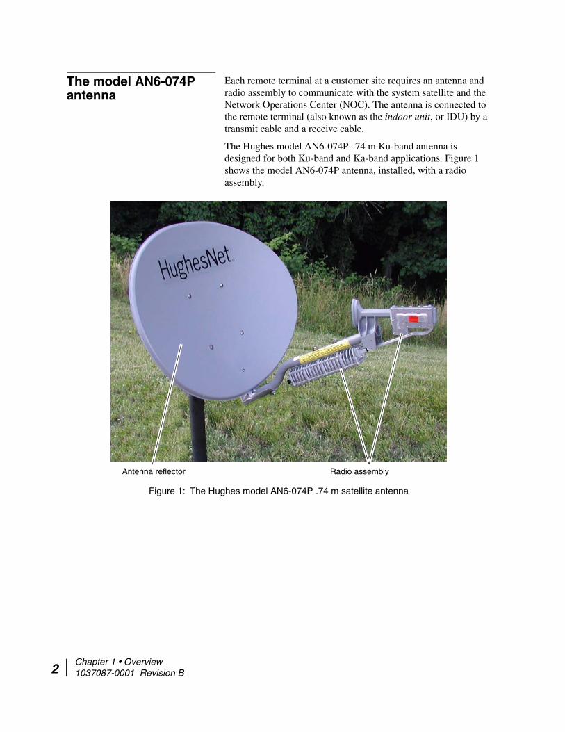
Each remote terminal at a customer site requires an antenna and radio assembly to communicate with the system satellite and the Network Operations Center (NOC). The antenna is connected to the remote terminal (also known as the indoor unit, or IDU) by a transmit cable and a receive cable.
The Hughes model AN6-074P .74 m Ku-band antenna is designed for both Ku-band and Ka-band applications. Figure 1 shows the model AN6-074P antenna, installed, with a radio assembly.
Figure 1: The Hughes model AN6-074P .74 m satellite antenna
Antenna reflector Radio assembly
Chapter 1 • Overview 1037087-0001 Revision B

Antenna installation summary
The antenna installation steps and related tasks are summarized below. The steps in bold type are documented in this manual.
1. Choose an installation site.2. Select a method for mounting the antenna.3. Install the antenna mount.
4. Install the IDU.
5. Determine the pointing values (azimuth, elevation, and polarization) – Chapter 3
6. Install polarization shim (only if required) – Chapter 37. Install the Az/El mount on the mast – Chapter 38. Install the antenna reflector – Chapter 39. Install the feed support arm – Chapter 3
10. Install the radio assembly – Chapter 311. Ground the antenna assembly.12. Run cables between the IDU and ODU locations.13. Connect cables to the ODU – Chapter 414. Point the antenna – Chapter 5
For the steps not shown in bold type, see the following section, Tasks related to antenna installation.
Note: A critical requirement is that the mast must be plumb. The antenna assembly cannot be adjusted to correct for a mast that is not plumb.
Note: Install the IDU before installing the antenna so you can run the installation software to determine the pointing values (azimuth, elevation, and polarization).
Note: Outdoor unit (ODU) refers to the antenna, radio assembly, and antenna mount.
Chapter 1 • Overview 1037087-0001 Revision B 3
4
Tasks related to antenna installation
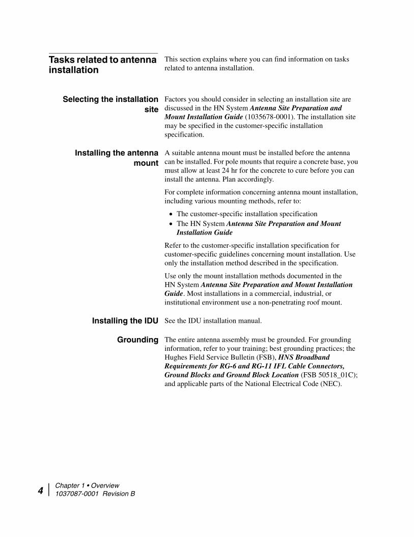
This section explains where you can find information on tasks related to antenna installation.
Selecting the installation site
Factors you should consider in selecting an installation site are discussed in the HN System Antenna Site Preparation and Mount Installation Guide (1035678-0001). The installation site may be specified in the customer-specific installation specification.
Installing the antenna mount
A suitable antenna mount must be installed before the antenna can be installed. For pole mounts that require a concrete base, you must allow at least 24 hr for the concrete to cure before you can install the antenna. Plan accordingly.
For complete information concerning antenna mount installation, including various mounting methods, refer to:
• The customer-specific installation specification• The HN System Antenna Site Preparation and Mount
Installation Guide
Refer to the customer-specific installation specification for customer-specific guidelines concerning mount installation. Use only the installation method described in the specification.
Use only the mount installation methods documented in the HN System Antenna Site Preparation and Mount Installation Guide. Most installations in a commercial, industrial, or institutional environment use a non-penetrating roof mount.
Installing the IDU See the IDU installation manual.
Grounding The entire antenna assembly must be grounded. For grounding information, refer to your training; best grounding practices; the Hughes Field Service Bulletin (FSB), HNS Broadband Requirements for RG-6 and RG-11 IFL Cable Connectors, Ground Blocks and Ground Block Location (FSB 50518_01C); and applicable parts of the National Electrical Code (NEC).
Chapter 1 • Overview 1037087-0001 Revision B
Approved cables For a list of approved cables for the interfacility link (IFL) between the antenna and the remote terminal, see the Hughes FSB, IFL Cable, Approved List (with lengths) for DW7x00, DW60xx, and DW40xx Domestic Installations (FSB_060316_01A). The FSB lists the maximum cable length for each approved cable type, for both 1-W and 2-W radios.
How the cable is run depends on the specific installation site. Route and connect the inter-facility link (IFL) cable according to your training and best practices.
Chapter 1 • Overview 1037087-0001 Revision B 5

6
Chapter 1 • Overview 1037087-0001 Revision B
Chapter 2
Antenna parts and required toolsThis chapter describes the components and parts provided with the model AN6-074P antenna kit. It includes the following sections:
• Antenna kit components on page 7• Small hardware parts list on page 12• Tools on page 13
Antenna kit components
This section identifies and describes the main components of the .74 m antenna kit. For an illustration of an installed .74 m antenna, see Figure 1 on page 2.
The main components of the antenna kit are:
• Az/El mount assembly• Antenna reflector• Reflector bracket and polarization plate• Tailpiece• Feed support arm• Feed horn
Related components:
• Radio assembly• Trimast or other mount
The radio assembly is included in this manual because the antenna and radio assembly are normally installed at the same time.
Chapter 2 • Antenna parts and required tools 1037087-0001 Revision B 7

8
In the following sections, each component of the antenna kit is shown and described. The components are in the order in which they are assembled.
Vertical shim kit (if required) If the installation specification states that vertical polarization is required, you will need to install a vertical shim kit in the radio assembly. Otherwise, a vertical shim (Figure 2) is not required. For more information, see Installing a shim for vertical transmit polarization on page 18.
Az/El mount assembly The Az/El mount assembly (Figure 3) supports the antenna and is used to point the antenna at the satellite.
Figure 2: Shim for vertical transmit polarization
Figure 3: Az/El mount assembly
Elevation scale
Canister
Chapter 2 • Antenna parts and required tools 1037087-0001 Revision B

Antenna reflector The antenna reflector is shown in Figure 4.
Reflector bracket and polarization plate
The reflector bracket and polarization plate are shown in Figure 5. The reflector bracket supports the antenna reflector. The polarization plate makes it possible to rotate the reflector to adjust polarization.
Figure 4: Antenna reflector
CAUTIONTo avoid damage to the antenna reflector, handle it with care.
Figure 5: Reflector bracket and polarization plate
Reflector bracket
Polarization plate
Chapter 2 • Antenna parts and required tools 1037087-0001 Revision B 9

10
Tailpiece The tailpiece is shown in Figure 6. The tailpiece attaches to the reflector bracket to provide a mounting point for the feed support arm.
Feed support arm Figure 7 shows the feed support arm, which supports the transmitter, TRIA, and feed horn.
Feed horn The feed horn transmits and receives signals to and from the reflector. It attaches to the TRIA.
Figure 6: Tailpiece
Top fits into reflector bracket.
Feed support arm attaches here.
Figure 7: Feed support arm
Feed horn attaches to this end.
Figure 8: Feed horn
Chapter 2 • Antenna parts and required tools 1037087-0001 Revision B

Related components The following sections describe the radio assembly and trimast.
Radio assembly The radio assembly (Figure 9) consists of the transmitter, low noise block converter (LNB), wave guide, and transmit/receive isolation assembly (TRIA).
The radio assembly is not part of the antenna kit. However, the antenna and radio assembly are normally installed at the same time, so instructions for installing the radio assembly are included in this manual.
Trimast (or other antenna mount)
The trimast is not part of the antenna kit. It is shown here because it is the most commonly used mounting option for the .74 m antenna. As shown in Figure 10, the trimast can be configured and manipulated in several ways to adapt it for mounting onto surfaces of various angles. For other suitable antenna mounting options, see the HN System Antenna Site Preparation and Mount Installation Guide (1035678-0001).
Figure 9: Radio assembly
Transmitter
TRIA
Wave guide
Figure 10: Trimast in various configurations
Wall
Flat roof Pitched roof
Mast
Struts (2)
T0144002
Chapter 2 • Antenna parts and required tools 1037087-0001 Revision B 11
12
Small hardware parts list
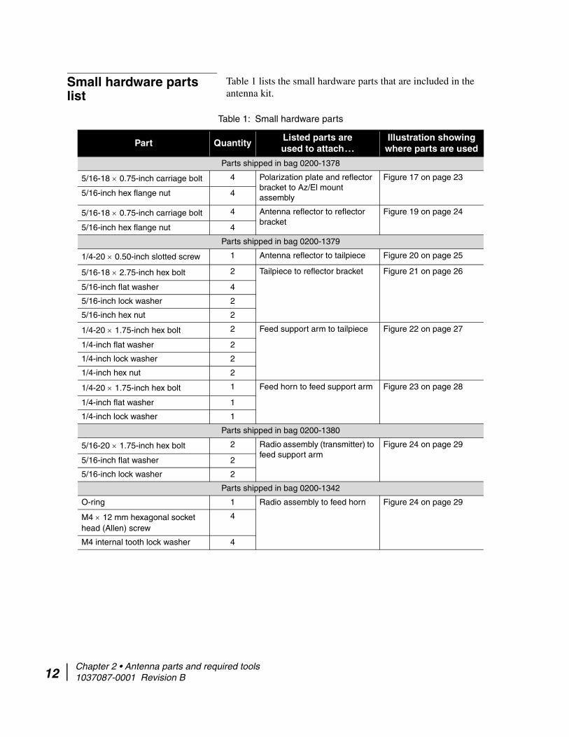
Table 1 lists the small hardware parts that are included in the antenna kit.
Table 1: Small hardware parts
Part QuantityListed parts are used to attach . . .
Illustration showing where parts are used
Parts shipped in bag 0200-1378
5/16-18 × 0.75-inch carriage bolt 4 Polarization plate and reflector bracket to Az/El mount assembly
Figure 17 on page 23
5/16-inch hex flange nut 4
5/16-18 × 0.75-inch carriage bolt 4 Antenna reflector to reflector bracket
Figure 19 on page 24
5/16-inch hex flange nut 4
Parts shipped in bag 0200-1379
1/4-20 × 0.50-inch slotted screw 1 Antenna reflector to tailpiece Figure 20 on page 25
5/16-18 × 2.75-inch hex bolt 2 Tailpiece to reflector bracket Figure 21 on page 26
5/16-inch flat washer 4
5/16-inch lock washer 2
5/16-inch hex nut 2
1/4-20 × 1.75-inch hex bolt 2 Feed support arm to tailpiece Figure 22 on page 27
1/4-inch flat washer 2
1/4-inch lock washer 2
1/4-inch hex nut 2
1/4-20 × 1.75-inch hex bolt 1 Feed horn to feed support arm Figure 23 on page 28
1/4-inch flat washer 1
1/4-inch lock washer 1
Parts shipped in bag 0200-1380
5/16-20 × 1.75-inch hex bolt 2 Radio assembly (transmitter) to feed support arm
Figure 24 on page 29
5/16-inch flat washer 2
5/16-inch lock washer 2
Parts shipped in bag 0200-1342
O-ring 1 Radio assembly to feed horn Figure 24 on page 29
M4 × 12 mm hexagonal socket head (Allen) screw
4
M4 internal tooth lock washer 4
Chapter 2 • Antenna parts and required tools 1037087-0001 Revision B

Tools Table 2 lists the tools required to assemble, install, and point the antenna.
Table 2: Tools required to install and point the antenna
Tool Details
(2) open-end or socket wrenches, 7/16-inch
For 1/4-inch bolts. Some nuts and bolts require a second wrench to prevent turning.
Socket wrench, 1/2-inch For 5/16-inch bolts.
Open-end wrench, 1/2-inch
For 5/16-inch bolts. Two of the canister nuts are not accessible with a socket wrench. Some nuts and bolts require a second wrench to prevent turning.
Torque wrench With 1/2-inch and 7/16-inch sockets capable of torquing to 8 ft-lb.
Long-shaft hexagonal ball driver, 3-mm
For Allen screws with a 3-mm hexagonal socket. Driver shaft should be at least 5 inches long.
Torque wrench for hexagonal socket
Must fit a 3-mm hexagonal socket and be capable of torquing to 15 in-lb.
Flat-blade screwdriver, 1/4-inch
For screw used to help secure antenna reflector to reflector bracket.
Bubble level Used to make sure the mast is plumb.
Compass
Pencil Carpenter’s pencil.
Outdoor pointing interface (OPI)
Optional. Hughes P/N 1031393-0002. Portable repeater that displays signal strength values during antenna pointing. For additional information, see Installing the OPI on page 40.
Fine elevation pointing tool
Hughes model DW-ELTOOL, P/N 1029130-0403. This tool allows you to make fine elevation adjustments when you point the antenna. For additional information, see Setting coarse elevation on page 43.
Chapter 2 • Antenna parts and required tools 1037087-0001 Revision B 13

14
Chapter 2 • Antenna parts and required tools 1037087-0001 Revision B
Chapter 3
Installing the antenna and radio assembly
This chapter explains how to assemble and install the antenna, radio, and associated hardware. Topics include:
• Determining the pointing values on page 16• General instructions for assembling the antenna on page 17• Installing a shim for vertical transmit polarization on
page 18• Installing the Az/El mount onto the mast pipe on page 22• Installing the antenna reflector on page 23• Installing the feed support arm on page 25• Installing the radio assembly on page 28
CAUTIONHN
Before you install the antenna, read all safety information in the section titled Important safety information on page iii.
Chapter 3 • Installing the antenna and radio assembly 1037087-0001 Revision A 15

16
Determining the pointing values
Before proceeding, use the installation software to determine the initial values to use for setting azimuth, elevation, and polarization. Record these values and keep them handy for reference as you install and point the antenna. In this manual, installation software refers to:
• Satellite-based commissioning (SBC) – This is the preferred and most automated method for pointing the antenna. You connect to a Web-based auto-commissioning system (WebACS) and follow the on-screen instructions.or
• WebSetup – You log onto an HN System Web site and use the WebSetup installation software. WebSetup requires an analog phone line.
You may use installation software from either of these sources. In each case, the software configures the IDU, calculates your exact location, and uses the location and other information to help you point the antenna. The installation software calculates the values you use to set azimuth, elevation, and polarization.
Follow the instructions in the IDU installation manual for accessing and using SBC or WebSetup.
For remote terminals (IDUs) produced before the HN7000S and HN7700S terminals, the installation software was provided on a compact disc (CD), so it could be loaded onto a PC. The HN7000S and HN7700S use SBC, and so they do not need installation software on a CD.
Chapter 3 • Installing the antenna and radio assembly 1037087-0001 Revision A
General instructions for assembling the antenna
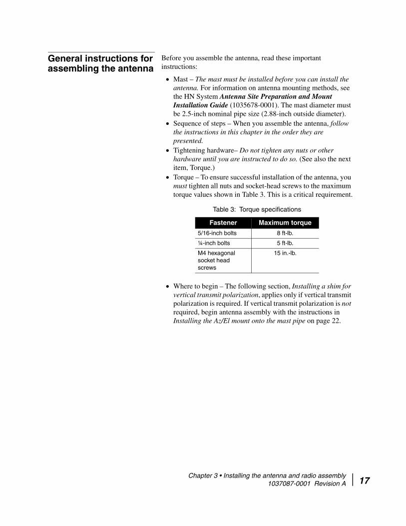
Before you assemble the antenna, read these important instructions:
• Mast – The mast must be installed before you can install the antenna. For information on antenna mounting methods, see the HN System Antenna Site Preparation and Mount Installation Guide (1035678-0001). The mast diameter must be 2.5-inch nominal pipe size (2.88-inch outside diameter).
• Sequence of steps – When you assemble the antenna, follow the instructions in this chapter in the order they are presented.
• Tightening hardware– Do not tighten any nuts or other hardware until you are instructed to do so. (See also the next item, Torque.)
• Torque – To ensure successful installation of the antenna, you must tighten all nuts and socket-head screws to the maximum torque values shown in Table 3. This is a critical requirement.
• Where to begin – The following section, Installing a shim for vertical transmit polarization, applies only if vertical transmit polarization is required. If vertical transmit polarization is not required, begin antenna assembly with the instructions in Installing the Az/El mount onto the mast pipe on page 22.
Table 3: Torque specifications
Fastener Maximum torque
5/16-inch bolts 8 ft-lb.
¼-inch bolts 5 ft-lb.
M4 hexagonal socket head screws
15 in.-lb.
Chapter 3 • Installing the antenna and radio assembly 1037087-0001 Revision A 17

18
Installing a shim for vertical transmit polarization
Follow the instructions in this section only if the installation specification or service order states that vertical transmit polarization is required.
If vertical transmit polarization is not required, go to Installing the Az/El mount onto the mast pipe on page 22.
The radio assembly is shipped with a horizontal transmit polarization shim installed. If vertical transmit polarization is required, you must remove the horizontal shim and replace it with a vertical transmit polarization shim.
Figure 11 shows where the shim is located and shows three of the four Allen screws that hold the shim in place.
To replace the horizontal shim with a vertical shim, follow these steps:
1. Obtain a vertical transmit polarization shim kit (Hughes model VTX-SHIM-KIT, P/N 1033809-0001).Figure 12 on page 19 shows what a vertical shim looks like.
2. Loosen and remove the four Allen screws that hold the shim in place. See Figure 11.
3. Separate the end of the waveguide from the shim.
Note: If you need to change from horizontal to vertical transmit polarization on an antenna that has the radio assembly already installed on the feed arm, you will have to remove the radio assembly from the feed arm before you can follow the instructions in this section.
Figure 11: Shim location next to TRIA
TRIA
Shim (See also Figure 12.)
Allen screws (4 total)
Waveguide
Chapter 3 • Installing the antenna and radio assembly 1037087-0001 Revision A

Figure 12 illustrates the difference between the horizontal shim and vertical shim. Note the positions of the alignment pins.
4. Remove the horizontal shim and O-ring.5. Install the vertical shim and O-ring in the same location.
Because of its shape and alignment pins on the transmit/receive isolation assembly (TRIA), the vertical shim can only be installed in the position shown in Figure 12 (upper right photo). Note the position of the alignment pins. Likewise, the horizontal shim can only be installed in one position.
Figure 12: Horizontal shim and vertical shim for transmit polarization
TRIA
Horizontal shim in place Vertical shim in place
(In this photograph, the TRIA has not yet been rotated.)
Alignment pins
O-ring
Horizontal shim Vertical shim
Alignment pins
Chapter 3 • Installing the antenna and radio assembly 1037087-0001 Revision A 19

20
Because of the shim’s alignment pins, you must rotate the TRIA 90 ° from its horizontal polarization position. You must rotate the TRIA before you re-attach the waveguide end so you can insert the shim alignment pins into the waveguide end plate. See Figures 13 and 14.
Figure 13: Direction of TRIA rotation for vertical polarization
Chapter 3 • Installing the antenna and radio assembly 1037087-0001 Revision A

Figure 14 shows how the TRIA is positioned for horizontal transmit polarization compared to how it is positioned for vertical transmit polarization.
6. Make sure the O-ring shown in Figure 13 on page 20 is in place in the shim.
7. With the TRIA correctly positioned (rotated), place the waveguide end plate against the shim.
8. Insert and tighten the four Allen screws.
At this point the radio assembly is ready to be installed. Set the assembly aside until you are ready to attach it to the feed support arm, as explained in Installing the radio assembly on page 28.
Figure 14: TRIA position for horizontal and vertical transmit polarization
Horizontal polarization
TRIA rotated for vertical polarization
TRIA
TRIA
Chapter 3 • Installing the antenna and radio assembly 1037087-0001 Revision A 21

22
Installing the Az/El mount onto the mast pipe
Follow these steps to install the Az/El mount assembly:
1. Before you install the Az/El mount assembly onto the mast pipe, use a bubble level to make sure the mast is level. Check the mast at two perpendicular locations, as shown in Figure 15.
2. Slide the Az/El canister down onto the mast as shown in Figure 16.
Figure 15: Making sure the mast is level
T0144012
Top view
To make sure the mast isplumb, check with the levelin two positions at rightangles to each other.
LevelMast
2nd levelposition
Mast
Bubble must be centeredbetween marks.
Bubblelevel
Side view
Note: The mast diameter must be 2.5-inch nominal pipe size (2.88-inch outside diameter).
Figure 16: Installing the Az/El mount assembly
Mast
Az/El mount assembly
Az/El canister
Chapter 3 • Installing the antenna and radio assembly 1037087-0001 Revision A

Installing the antenna reflector
Attach the antenna reflector bracket to the Az/El mount:
1. Hold the reflector bracket and polarization plate in the positions shown in Figure 17.Position the reflector bracket and polarization plate so you can insert all four bolts and clearly see the polarization scale, as shown in Figure 18. It doesn’t matter which direction the two flat surfaces of the polarization plate point toward.
2. Insert four carriage bolts (5/16-inch-18 × 0.75-inch) through the polarization plate, reflector bracket, and Az/El mount.
3. Place a 5/16-inch hex flange nut on each of the four bolts. 4. Tighten the nuts lightly, only until they are snug.
Note: Tighten all 5/16-inch bolts to a maximum torque of 8 ft-lb.
Figure 17: Attaching the reflector bracket and polarization plate
Polarization plate
Reflector bracket attached
Reflector bracket
Chapter 3 • Installing the antenna and radio assembly 1037087-0001 Revision A 23

24
When the reflector bracket is correctly positioned, you can clearly see the polarization scale and numbers above the polarization pointer, as shown in Figure 18.
Attach the antenna reflector:
1. Hold the reflector against the reflector bracket with the tailpiece notch oriented at the bottom of the reflector. See Figure 19.
2. Insert four carriage bolts (5/16-inch-18 × 0.75-inch) through the front of the reflector and bracket.
3. From the back of the reflector bracket, secure the bolts with four 5/16-inch hex flange nuts.
4. Tighten the nuts lightly, only until they are snug.
Figure 18: Polarization scale
Polarization pointer
Figure 19: Attaching the antenna reflector
Reflector attached
Reflector
Tailpiece notch
Chapter 3 • Installing the antenna and radio assembly 1037087-0001 Revision A

Installing the feed support arm
To install the feed support arm, you first attach the tailpiece to the antenna reflector bracket, then you insert the feed support arm into the tailpiece.
Installing the tailpiece Refer to Figure 20, and attach the tailpiece to the reflector bracket, as follows:
1. Insert the tailpiece into the reflector bracket with the tailpiece notch and the tailpiece key aligned.
2. Insert the ¼-inch screw through the reflector and into the tailpiece.
3. Tighten the ¼-inch screw.You must tighten this screw before tightening any other hardware so you can properly align the feed support arm to the reflector.
Note: You must complete the steps in this section (steps 1 through 6) before you attach the feed support arm. This is necessary so you can properly align the feed support arm to the antenna reflector.
Note: Do not tighten any hardware until instructed.
Figure 20: Inserting the tailpiece into the reflector bracket
Tailpiece key
Tailpiece notch
Tailpiece
1/4-inch screw
Tailpiece key (close-up)
Chapter 3 • Installing the antenna and radio assembly 1037087-0001 Revision A 25

26
4. Insert two 5/16-inch × 2.75-inch bolts, with 5/16-inch flat washers, through the reflector bracket and tailpiece, as shown in Figure 21.
5. Place the flat washers, lock washers, and hex nuts (all 5/16-inch) over the bolt, as shown in Figure 21.
6. Tighten the two 5/16-inch hex nuts.
Figure 21: Inserting the tailpiece bolts
Tailpiece installed, viewed from behind antenna
Tailpiece bolts
Washer arrangement
Reflector bracket
Tailpiece
Flat washer
Lock washer
Flat washer
Chapter 3 • Installing the antenna and radio assembly 1037087-0001 Revision A

Inserting and attaching the feed support arm
Insert and attach the feed support arm:
1. Insert the feed support arm into the tailpiece, as shown in Figure 22.
2. Insert two ¼-inch × 1.75-inch bolts through the tailpiece and feed support. See Figure 22.
3. Place flat washers, lock washers, and hex nuts (all 5/16 inch) on the bolts.
4. Tighten the hex nuts.
Figure 22: Attaching the feed support arm to the tailpiece
Feed support arm
Bolts (2)
Feed support arm, installed
Chapter 3 • Installing the antenna and radio assembly 1037087-0001 Revision A 27

28
Installing the radio assembly
Attach the feed horn to the feed support arm:
1. Position the feed horn near the end of the feed support arm as shown in Figure 23. Note that there is a peg on the bottom of the feed horn that fits into the small hole closest to the end of the feed support arm. This peg is shown in Figure 23. The second hole (closest to the antenna reflector) is for the bolt that secures the feed horn.
2. Insert the ¼-inch × 1.75-inch bolt, with ¼-inch flat washer and lock washer, through the feed support arm and into the feed horn.
3. Tighten the ¼-inch bolt.
Install the radio assembly (transmitter and TRIA):
1. Position the radio assembly below the feed support arm as shown in Figure 24.
2. Insert two 5/16-inch × 1.75-inch bolts, with 5/16-inch flat washers, and lock washers, through the feed support arm and into the transmitter. Leave these bolts loose so you can insert the O-ring (step 3).
3. Separate the rear end of the feed horn from the radio assembly enough to allow you to insert the O-ring into the end of the feed horn, as shown in Figure 24.
4. Insert the O-ring.
Figure 23: Installing the feed horn
Feed horn bolt
Feed horn installed on support arm
Feed horn
PegBolt
Close-up view
Peg hole
Chapter 3 • Installing the antenna and radio assembly 1037087-0001 Revision A

5. Attach the radio assembly to the feed horn using the provided M4 × 12-mm socket-head screws with M4 lock washers (with teeth on the inner edges).Make sure the O-ring remains in the O-ring groove.
6. Use a long-shaft ball driver 3-mm Allen wrench to tighten the socket-head screws to 15 in-lb force (maximum).
7. After the radio assembly is assembled, tighten the two 5/16-inch bolts to secure the transmitter.
At this point, fully tighten any hardware that is not tight—however, leave nuts that are used for pointing adjustments loose or just snug. These nuts are shown in Figure 33 on page 42.
Figure 24: Installing the radio assembly
Installed radio assembly
O-ring
Radio assembly
Bolts
Chapter 3 • Installing the antenna and radio assembly 1037087-0001 Revision A 29

30
This completes assembly of the antenna. The antenna should like the one in Figure 24, depending on its orientation.
To complete the antenna installation, you still need to run cables to connect the antenna to the remote terminal, as explained in Chapter 4 – Cabling and connections, and point the antenna at the satellite, as explained in Chapter 5 – Pointing the antenna.
Figure 25: Assembled antenna
Chapter 3 • Installing the antenna and radio assembly 1037087-0001 Revision A

Chapter 4
Cabling and connectionsThis chapter illustrates where the ODU transmit, receive, and ground connectors are located; shows how to route the transmit and receive cables at the ODU; and explains how to connect the transmit and receive cables to the radio assembly. You must connect the transmit, receive, and ground cables before you can point the antenna (Chapter 5 – Pointing the antenna).
The chapter includes these sections:
• Previous cabling work on page 31• Routing the cables at the ODU on page 32• Connecting the transmit and receive cables on page 33• Ground connection on page 35
Previous cabling work Before you perform the steps explained in this chapter, you must route and terminate the transmit and receive cables from the IDU to the ODU.
For a list of approved cables for the interfacility link (IFL) between the antenna and the remote terminal, see the Field Service Bulletin (FSB), IFL Cable, Approved List (with lengths) for DW7x00, DW60xx, and DW40xx Domestic Installations (FSB_060316_01A). This FSB lists the maximum cable length for each approved cable type, for both 1-W and 2-W radios.
How the cables are run depends on the specific installation site. Route and connect the cables according to your training and best practices.
CAUTIONCoaxial connectors and cable can corrode if exposed to moisture. Use only compression type connectors, and weatherproof them with dielectric grease and weatherproof tape.
Note: For connector requirements, see the Hughes FSB, HNS Broadband Requirements for RG-6 and RG-11 IFL Cable Connectors, Ground Blocks and Ground Block Location (FSB 50518_01C).
Chapter 4 • Cabling and connections 1037087-0001 Revision B 31

32
Routing the cables at the ODU
Route the coaxial transmit and receive cables at the ODU as follows:
1. Route the transmit cable (marked with blue electrical tape) over the Az/El mount assembly and behind the reflector to the back of the transmitter, in a configuration similar to that shown in Figure 26.Do not exceed the minimum bending radius specified by the cable manufacturer.
2. For the transmit cable, leave a 152-inch service loop (12 ft 7 inches), secured to the mast, Az/El mount assembly, or reflector bracket. This allows 10 ft for a service loop plus 32 inches for installation of a future Ka-band radio upgrade.Do not leave the service loop on the roof or other mounting surface.Do not block access to the adjustment nuts on the canister and Az/El mount assembly.
3. Coil the extra cable, leave a drip loop, and secure the transmit cable with cable ties.
Figure 26: Transmit and receive cable configurations
T0144011
Transmitter
Transmit cable(marked withBLUE tape)
Receive cable(marked withRED tape)
Radio
Do not exceed thecable bending radius.
Secure cables withcable ties (not shown).
Service loops for transmit andreceive cables. Coiled, with drip loops.
Chapter 4 • Cabling and connections 1037087-0001 Revision B

4. Route the receive cable (marked with red electrical tape) over the Az/El mount assembly, behind the reflector, and along the feed support arm to the TRIA, in a configuration similar to that shown in Figure 26.Do not exceed the minimum cable bending radius.
5. For the receive cable, leave a 138-inch service loop (11.5 ft), secured to the mast, Az/El mount assembly, or reflector bracket. This allows 10 ft for a service loop plus 18 inches for installation of a future Ka-band radio upgrade.
6. Coil the extra cable, leave a drip loop, and secure the receive cable with cable ties.
Connecting the transmit and receive cables
This section explains how to connect the transmit and receive cables to the radio assembly.
Transmit cable Connect the transmit cable to the transmitter as follows:
1. From inside the building, disconnect the IDU power supply.2. Go outside and connect the transmit cable (marked with blue
electrical tape) to the transmitter connector marked IFL, as shown in Figure 27.
3. Tighten the connection with a 7/16-inch wrench.
CAUTIONCoaxial connectors and cable can corrode if exposed to moisture. Use only compression type connectors, and weatherproof them with dielectric grease and weatherproof tape.
Figure 27: Transmit connector (arrow) – female F connector
Chapter 4 • Cabling and connections 1037087-0001 Revision B 33

34
4. If necessary, secure the cable with cable ties.
Receive cable Connect the receive cable to the LNB as follows:
1. Connect the receive cable (marked with red tape) to the receive connector on the LNB, which is illustrated in Figure 28.
2. Tighten the cable connector with a 7/16-inch wrench.3. Apply dielectric silicone grease to the connection.4. If necessary, secure the cable with cable ties.
After the transmit and receive cables are connected to the radio and to the IDU, reconnect the power transformer (inside the building). Instructions for connecting the IDU are included in the IDU installation manual.
Figure 28: Receive connector (arrow) – female F connector
Chapter 4 • Cabling and connections 1037087-0001 Revision B

Ground connection Figure 29 shows the location of the ground screw on the transmitter. Ground the transmitter and mast. For specific grounding procedures, refer to the sources listed in Grounding on page 4.
Figure 29: Ground screw on the transmitter (arrow)
(Not used)
Chapter 4 • Cabling and connections 1037087-0001 Revision B 35

36
Chapter 4 • Cabling and connections 1037087-0001 Revision B
Chapter 5
Pointing the antenna This chapter explains how to point the antenna. Topics include:
• Antenna pointing overview on page 38• Prerequisites for antenna pointing on page 39• Outdoor pointing interface on page 39• Adjusting the antenna on page 41• Setting coarse elevation on page 43• Fine elevation pointing tool on page 44• Receive pointing on page 46• Isolating the transmit signal on page 50• Final steps on page 52
As you perform these procedures, observe the following safety precautions:
CAUTION• This device emits radio frequency energy when in
transmit mode. To avoid injury, do not place head or other body parts between feed horn and antenna when system is operational. Keep at least 2 ft away from the area between the feed horn and the reflector when the system is operational.
• Make sure the cylindrical space projecting outward from the antenna reflector toward the satellite does not intersect or come close to any inhabited areas.
• Disconnect power from the IDU before performing maintenance or adding upgrades to any antenna components.
Chapter 5 • Pointing the antenna 1037087-0001 Revision B 37

38
Antenna pointing overview
This chapter describes a general procedure for pointing the antenna. The objectives of antenna pointing are to:
• Locate and detect the satellite signal• Peak the signal to achieve the greatest possible signal
strength
Using the installation software
The exact pointing procedure depends on the installation software used, SBC or WebSetup. (For a description of SBC and WebSetup, see Determining the pointing values on page 16.)
The installation software guides you through a step-by-step process for installing the IDU and pointing the antenna. It calculates your exact location and the values you use to set polarization, elevation, and azimuth.
Use the information in this chapter as a guide for the overall pointing process and for instructions on how to make mechanical adjustments to the antenna. For specific steps, follow the instructions in the IDU manual and on the installation software screens.
In general you will alternate between these two activities:
• Following the software prompts and instructions• Adjusting the antenna (azimuth, elevation, and polarization)
to acquire and then peak the satellite signal. The required adjustments are different for each installation location.
Peaking the signal Correct antenna alignment is critical to the operation of the system. When the antenna is pointed directly at the satellite, it receives a strong signal. If it is not pointed properly, the signal may be weak, and errors may result during data transfers.
Antenna pointing is accomplished by first receive pointing the antenna and then isolating the transmit signal. Receive pointing adjusts the antenna to obtain the best receive signal. Isolating the transmit signal fine tunes the antenna alignment for the strongest possible signal received by the HN System NOC. Both processes are explained later in this chapter.
To point the antenna, you go through cycles of making small adjustments to the antenna until you are satisfied you cannot get a stronger satellite signal. When you have achieved the strongest possible signal, you have peaked the signal.
You may achieve the strongest signal strength after just a few adjustments, or you may find that several adjustments are needed. By obtaining the strongest possible signal you ensure that the terminal can operate with peak performance.
Chapter 5 • Pointing the antenna 1037087-0001 Revision B
Personnel requirements One person can point the antenna if an outdoor pointing interface (OPI) is used. Otherwise, pointing is usually a two-person task. One person aims and adjusts the antenna while the other watches the signal strength display on the computer and relays the readings to the person at the antenna. A portable telephone or walkie-talkie is helpful for this.
Pointing parameters Prior to antenna pointing, you use the installation software to enter parameters such as longitude, latitude, and polarization angle. Or you can enter the local ZIP code and let the software calculate these values.
Prerequisites for antenna pointing
The following are required for antenna pointing:
• The antenna must be installed.• The IDU must be installed.• The transmit and receive cables must be connected to the
IDU and ODU.• The outdoor pointing interface (OPI), if used, must be
installed. (See Installing the OPI on page 40.)• You must have a fine elevation pointing tool. (See Fine
elevation pointing tool on page 44.)• The ODU and IDU must be grounded.• You must have access to the installation software. (See Using
the installation software on page 38.)
Outdoor pointing interface
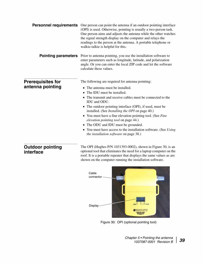
The OPI (Hughes P/N 1031393-0002), shown in Figure 30, is an optional tool that eliminates the need for a laptop computer on the roof. It is a portable repeater that displays the same values as are shown on the computer running the installation software.
Figure 30: OPI (optional pointing tool)
Cable connector
Display
Chapter 5 • Pointing the antenna 1037087-0001 Revision B 39

40
Installing the OPI To prepare for antenna pointing, attach the OPI to the receive cable from the LNB, as shown in Figure 31. Note that the OPI will not work unless it is enabled on the appropriate screen on the installation software. (Check the box labeled Enable OPI Display.)
For further details, see Outdoor Pointing Interface Operating Instructions (1031832-0001).
OPI block If you use an OPI with a model RA6-074 radio assembly, you must use a block (or filter). For details, including the specific block you should use, see the Hughes Field Service Bulletin (FSB), Standard OPI Configuration (FSB_060915_01A).
Install the block between the OPI and the radio as illustrated in Figure 31. If the block you use has two female F connectors (at both ends), you will have to make a jumper cable to connect to the OPI.
Figure 31: Installing the OPI
T0144013
Block(if required)
OPI
Groundblock
IDU
LNB
Chapter 5 • Pointing the antenna 1037087-0001 Revision B

Adjusting the antenna To point the antenna you make three adjustments to the position of the antenna reflector:
• Elevation – Adjustment up and down• Polarization – Rotational adjustment• Azimuth – Side-to-side adjustment
These adjustments are illustrated in Figure 32. The corresponding mechanical adjustments on the antenna are shown in Figure 33.
Figure 32: Adjusting azimuth, elevation, and polarization
T0144003
-x ° +x °0 °
Antenna reflectorpolarizationadjustment,front view
Polarization
Polarization
-x °
+x °
0°
Elevation
Elevation
LOS to satellite
Azimuth
Positive (+)
Negative (-)-x °
+x °0°
Azimuth
Note: When recording or using antenna pointingvalues, you must pay attention to whethervalues are positive (+) or negative (-).
Chapter 5 • Pointing the antenna 1037087-0001 Revision B 41

42
Adjustment locations on the antenna
Figure 32 shows the mechanical adjustments for azimuth, elevation, and polarization. All pointing adjustments require a 1/2-inch wrench.
Detailed procedures for adjusting the antenna are included in the sections that follow. As you make pointing adjustments, tighten the lockdown nuts enough to prevent movement of the antenna reflector. When you are done pointing, you fully tighten all lockdown nuts.
Figure 33: Pointing adjustments on the antenna—azimuth, elevation, and polarization
Canister nuts (3). Loosen to adjust azimuth.
Polarization lockdown nuts (4)
Elevation scale
Elevation lockdown nuts (2)(coarse elevation adjustment)
(The polarization scale is shown in Figure 37 on page 46.)
Fine elevation adjustment
Chapter 5 • Pointing the antenna 1037087-0001 Revision B

Setting coarse elevation The antenna pointing procedure begins with the steps described in this section and continues through the end of this chapter. Follow the instructions in the order they are presented.
Before installing the pointing tool, set the initial (coarse) antenna elevation to the initial elevation value given by the installation software, as follows:
1. Loosen the two elevation lockdown nuts indicated in Figure 34, a little at a time, until you can rotate the antenna reflector forward and backward to adjust the elevation.
2. Set the elevation to the value given by the installation software.
CAUTIONTo avoid bending the antenna reflector, move the reflector by holding the reflector bracket. If you hold the reflector by its edges, you may bend it.
Figure 34: Setting coarse elevation
Elevation scale Elevation lockdown nuts (2)
Reflector bracket
Arrows indicate movement during elevation adjustment.
Chapter 5 • Pointing the antenna 1037087-0001 Revision B 43

44
Fine elevation pointing tool
The fine elevation pointing tool (Hughes P/N 1029130-0403, shown in Figure 35) attaches to the Az/El mount assembly, allowing you to make fine adjustments of the antenna elevation. You install and use this tool for pointing; then remove it for re-use in subsequent installations.
Installing the pointing tool Refer to Figure 35 and follow these steps to install the fine elevation pointing tool:
1. Attach the lower bracket that is attached to the pointing tool to the bracket that is attached to the canister:a. Insert the fixed bolts on the tool’s lower bracket (black
arrows in Figure 35) into the two holes in the canister bracket.
b. Place the nuts on the fixed bolts and tighten them.
2. Attach the upper bracket on the pointing tool to the top of the Az/El mount assembly:a. Remove the wing nut and 4-inch-long bolt (white arrow in
Figure 35) from the pointing tool’s upper bracket.b. Place the pointing tool upper bracket onto the Az/El mount
assembly as shown in Figure 35, and insert the 4-inch bolt.c. Replace the wing nut on the bolt and tighten it.
Figure 35: Installing the fine elevation pointing tool
Fine elevation pointing tool
Pointing tool upper bracket
Pointing tool lower bracket
Canister
Elevation lockdown nut (1 on each side)
Chapter 5 • Pointing the antenna 1037087-0001 Revision B

Fine elevation adjustment Where subsequent instructions call for fine adjustment of the antenna elevation, fine-tune the elevation setting as follows:
1. Make sure the two elevation lockdown nuts are loose enough to allow the reflector to move as indicated by the arrows in Figure 36.
2. While watching the signal strength display, adjust the elevation adjustment nuts on the pointing tool (Figure 36) to achieve maximum signal strength:a. Move the top nut to allow movement, then make
adjustments with the bottom nut. b. Adjust by turning the bottom nut a few turns clockwise and
counterclockwise, until you peak the signal.
3. When the signal is peaked, tighten the two elevation lockdown nuts.
Figure 36: Elevation adjustments on the antenna
Elevation lockdown nut (1 on each side)
Elevation scale
Fine elevation adjustment nuts
Chapter 5 • Pointing the antenna 1037087-0001 Revision B 45

46
Receive pointing Receive pointing peaks the receive signal. You must peak the signal even if the antenna is locked to it.
You use the installation software to check the signal strength. Then you adjust the antenna to peak the signal. The installation software shows numerical and graphic indications of signal strength. Detailed instructions for these procedures are given in the following sections.
Initial elevation setting Make sure the antenna is set to the initial elevation value given by the installation software. If you have followed the previous instructions—to set the initial elevation before you install the fine elevation pointing tool—this step will already be done.
Setting polarization Set polarization to the initial polarization value given by the installation software.
Polarization refers to rotation of the antenna (as shown in Figure 32 on page 41) and is measured in degrees from zero (no rotation), positive or negative. Polarization is positive east of the satellite longitude and negative west of the satellite longitude.
To set polarization, refer to Figure 37 and follow these steps:
1. Loosen the four polarization lockdown nuts just enough so you can rotate the antenna reflector.
2. Rotate the antenna to the initial polarization value as indicated by the polarization scale.
Figure 37: Polarization adjustments on the antenna
Polarization lockdown nuts (4)
Polarization scale
Scale pointer
The fine elevation pointing tool is not included in this photo to allow a better view of the polarization scale and pointer.
Arrows indicate movement during polarization adjustment.
Chapter 5 • Pointing the antenna 1037087-0001 Revision B
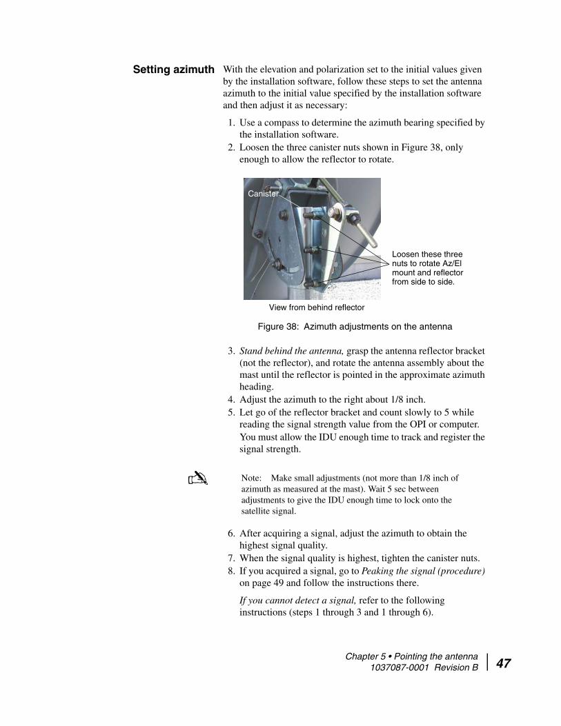
Setting azimuth With the elevation and polarization set to the initial values given by the installation software, follow these steps to set the antenna azimuth to the initial value specified by the installation software and then adjust it as necessary:
1. Use a compass to determine the azimuth bearing specified by the installation software.
2. Loosen the three canister nuts shown in Figure 38, only enough to allow the reflector to rotate.
3. Stand behind the antenna, grasp the antenna reflector bracket (not the reflector), and rotate the antenna assembly about the mast until the reflector is pointed in the approximate azimuth heading.
4. Adjust the azimuth to the right about 1/8 inch.5. Let go of the reflector bracket and count slowly to 5 while
reading the signal strength value from the OPI or computer. You must allow the IDU enough time to track and register the signal strength.
6. After acquiring a signal, adjust the azimuth to obtain the highest signal quality.
7. When the signal quality is highest, tighten the canister nuts.8. If you acquired a signal, go to Peaking the signal (procedure)
on page 49 and follow the instructions there.
If you cannot detect a signal, refer to the following instructions (steps 1 through 3 and 1 through 6).
Figure 38: Azimuth adjustments on the antenna
Loosen these three nuts to rotate Az/El mount and reflector from side to side.
Canister
View from behind reflector
Note: Make small adjustments (not more than 1/8 inch of azimuth as measured at the mast). Wait 5 sec between adjustments to give the IDU enough time to lock onto the satellite signal.
Chapter 5 • Pointing the antenna 1037087-0001 Revision B 47

48
If no signal is present:
1. Repeat steps 3 through 5 in Setting azimuth on page 47. (Adjust the reflector to about 1/8 inch to the right of the approximate azimuth.)
2. Keep moving the antenna reflector to the right a little at a time until you detect a signal.
3. If there is no signal, sweep back 1/8 inch at a time to the left until you detect a signal.
If you still cannot detect a signal, there may be an error. If there is no signal, perform the following quick checks.
1. Check the coaxial cable connections at the LNB, IDU, and all the connections in between.
2. Make sure there are no obstructions such as trees blocking the signal.
3. Make sure you recorded and properly set the azimuth, elevation, and polarization values.
4. Verify the azimuth setting by moving 15 ft in front of or behind the antenna and taking another compass reading. Metal near the compass, such as a car or even a belt buckle, can give a false reading.
5. Point the front of the antenna reflector to the left of the estimated bearing.
6. Go back to step 3 in Setting azimuth on page 47 and try again.
After you have acquired the signal and obtained the highest signal quality, tighten the canister nuts.
Chapter 5 • Pointing the antenna 1037087-0001 Revision B

Peaking the signal (procedure)
After the satellite signal is detected, peak the signal as follows:
1. Mark the mast with a pencil so you can find the azimuth bearing again.
2. After detecting the satellite, continue turning the antenna reflector a small amount in the same direction you were turning it when you began receiving the satellite signal. Pause for 5 sec after each time you move the reflector.
3. Turn the reflector in this fashion until the signal strength values displayed by the installation software begin to decrease.
4. When the numbers begin to decrease, slowly turn the reflector in the opposite direction until you regain the highest number that was previously achieved. (Achieving this maximum signal strength is called peaking the signal.)
5. When you have peaked the azimuth, tighten the three canister nuts completely.
6. After fine-tuning the antenna azimuth, erase all marks previously made on the mast.
7. Adjust the elevation and polarization, as necessary, to obtain the highest quality signal.
8. Tighten all adjustment nuts.
Chapter 5 • Pointing the antenna 1037087-0001 Revision B 49

50
Isolating the transmit signal
To prevent signal cross talk, you use a procedure known as Automated Cross Polarization (ACP) to isolate the transmit signal from the receive signal. ACP test functions are included in the installation software.
The ACP software operates in two different modes—manual or automatic. Manual mode gives real-time feedback of cross polarization isolation measurements while you adjust the antenna. Automatic mode takes a snapshot of the cross polarization isolation measurement.
ACP fine pointing consists of testing using both the manual and automatic modes and adjusting the antenna by small increments (if necessary) until it passes both the manual and automatic ACP tests.
Follow the general instructions below for the ACP tests. Use the installation software screens to initiate tests and see the test results.
Manual ACP test First run a manual ACP test:
1. Lock down all antenna adjustment nuts and bolts.2. Initiate the manual ACP test.
Select the manual cross polarization test type.
If the manual ACP test passes, stop the test and proceed to Automatic ACP test on page 51.
If the manual ACP test fails, let the test continue and follow these steps:
1. Loosen the two elevation lockdown nuts. 2. Peak the elevation setting by making small adjustments to the
nuts on the fine elevation pointing tool.Do not turn the lower adjustment nut more than one-quarter of a turn at a time. For all ACP test adjustments, make very small adjustments. If you adjust too much, you lose the receive signal and the test cannot continue because you are out of contact with the NOC. You then have to go back to the receive pointing instructions (Receive pointing on page 46) and perform that procedure again.
3. Tighten the two elevation lockdown nuts.
Note: When you adjust any one of the axes—elevation, polarization, or azimuth—you may also have to adjust one or both of the other axes.
Chapter 5 • Pointing the antenna 1037087-0001 Revision B

If the manual ACP test passes, stop the test and proceed to Automatic ACP test on page 51.
If the manual ACP test fails after you adjust the elevation, let the test continue and follow these steps:
1. Mark the present azimuth position with a pencil so you can return to it.
2. Loosen the three nuts on the canister just enough so you can change the azimuth.
3. Observe the signal strength while you make very small adjustments—1/16 inch or less movement of the Az/El assembly on the mast.
4. Peak the azimuth to the highest possible signal strength value.
5. Tighten the three nuts on the canister flange to lock down the azimuth adjustment.
6. Run the automatic ACP test, as explained in Automatic ACP test.
Automatic ACP test Initiate the automatic ACP test by selecting the automatic cross polarization test type. If the antenna passes the ACP test and maintains signal strength within 3 points on the signal strength scale, it is pointed and ready to be registered.
If the antenna fails the ACP test, follow these steps:
1. Initiate a manual ACP test.2. When the test starts, make small, 1 ° or less changes in
polarization while observing the transmitter isolation.3. Peak the polarization to the highest possible transmitter
isolation.4. Tighten the polarization lockdown nuts.5. If the antenna passes the manual test, stop the manual test and
run the automatic ACP test again.6. Check the signal strength.
If the antenna passes the ACP test and maintains signal strength within 3 points, it is pointed and ready to be registered.
If the antenna passes the automatic ACP test, but the signal strength drops more than 3 points after the test, you must repeat the fine adjustments for azimuth and elevation:
1. Repeat the fine adjustments for both azimuth and elevation to maximize the signal strength.
2. Repeat the ACP test.3. Check the signal strength.
Chapter 5 • Pointing the antenna 1037087-0001 Revision B 51

52
If the antenna passes the ACP test and maintains signal strength within 3 points, it is pointed and ready to be registered.
If the antenna still does not meet both criteria, repeat the very small polarization, azimuth, and elevation adjustments and ACP tests as many times as necessary until you have peaked the signal and the antenna passes the automatic ACP test and signal strength is maintained within 3 points.
Important: When you are finished pointing the antenna, lock down all pointing adjustments. All adjustment points are shown in Figure 33 on page 42.
Final steps Complete the following steps before leaving the installation site.
Remove the OPI and fine elevation pointing tool
Remove the OPI and fine elevation pointing tool so you can re-use them for subsequent installations.
Remove the OPI:
1. Disconnect the OPI and block, if used.2. Reconnect the receive cable to the radio.
Remove the pointing tool:
1. Remove the pointing tool’s upper and lower brackets from the Az/el assembly and canister.
2. Replace the nuts and bolts on the pointing tool’s tool brackets so they will not get lost.
Check for safety labels and signs
Make sure the required safety labels and/or signs are present:
• Make sure a Radiation Hazard Caution label is present, legible, and visible on the feed arm and on the back of the antenna reflector.
• If the antenna is enclosed by a fence, make sure a Radiation Hazard Caution sign is present, legible, and visible on the entrance gate.
• If the antenna is installed on a roof with a permanently mounted access ladder, make sure a Radiation Hazard Caution sign is present, legible, and visible on or near the ladder.
Subsequent steps The antenna is now installed and pointed, ready for operation.
To commission the IDU (remote terminal), refer to the IDU installation manual.
Chapter 5 • Pointing the antenna 1037087-0001 Revision B
Acronyms and abbreviations
A
ACP – Automated Cross Polarization
Az/El – Azimuth and elevation
C
CD – Compact disc
F
FSB – Field service bulletin
ft – Foot
ft-lb – Foot-pound
H
hr – Hour
I
IDU – Indoor unit
IFL – Inter-facility link
in.-lb – Inch-pound
L
LNB – Low noise block converter
N
NEC – National Electrical Code
NOC – Network Operations Center
O
ODU – Outdoor unit
OPI – Outdoor pointing interface
P
P/N – Part number
R
RF – Radio frequency
S
SBC – Satellite-based commissioning
sec – Second
T
TRIA – Transmit/receive isolation assembly
W
WebACS – Web-based auto-commissioning
• Acronyms and abbreviations 1037087-0001 Revision B 53

54
• Acronyms and abbreviations 1037087-0001 Revision B
Index
A
Antennaillustrated 2, 30kit components 7mount 4pointing 38
isolating the transmit signal 50mechanical adjustments 42peaking the signal 38, 49prerequisites 39receive pointing 46
reflector 9installing 23
Az/El mount assembly 8, 22Azimuth, adjusting 47
C
Cables 31approved types 5connecting to radio assembly 33maximum length 5receive cable 34routing at the ODU 32service loop 32transmit cable 33
Components 7Connecting
cables to the radio assembly 33receive cable 34transmit cable 33
Connectors 31
E
Elevationadjusting 43, 45fine adjustment 45
F
Feed horn 10installing 28
Feed support arm 10installing 25
Final steps 52Fine elevation pointing tool
installing 44removing 52using 45
G
Grounding 4ground screw location 35
H
Hardware parts list 12
I
IFL 5, 31Installation site 4Installation software 16, 38Installation, summary of steps 3Installing
antenna reflector 23feed horn 28feed support arm 25final steps 52fine elevation pointing tool 44OPI 40polarization plate 23radio assembly 28reflector bracket 23tailpiece 25
Isolating the transmit signal 50
• Index 1037087-0001 Revision B 55

56
L
Leveling the mast 22
M
Mast 17Mount 23Mount for antenna 4, 23
O
OPI 39purpose 39removing 52
OPI block 40Outdoor pointing interface. See OPI
P
Parts list 12Peaking the signal 38, 49Pointing values 16Pointing. See Antenna, pointingPolarization
adjusting 46shim for vertical or horizontal transmit
polarization 18Polarization plate 9Polarization scale 24
R
Radio assembly 11installing 28shim kit 18
Receive cableconnecting to the LNB 34routing 33
Receive pointing 38, 46Reflector 9Reflector bracket 9
S
Safety labels and/or signs 52Shim for transmit polarization 8, 18Signal strength 45, 51Signal strength, maximizing 49Summary of installation steps 3
T
Tailpiece 10Tasks 3
related to antenna installation 4Tool list 13Torque 17Transmit cable
connecting 33routing 32
Transmit polarization shim 18Transmit signal, isolating 50Transmitter 11
connecting 33Trimast 11
V
Vertical shim kit 8, 18
• Index 1037087-0001 Revision B