history of geologic investigations, engineering design ... · history of geologic investigations,...
TRANSCRIPT

History of Geologic Investigations, Engineering Design, and Construction Methods of the Harold D. Roberts Tunnel, Colorado
GEOLOGICAL SURVEY PROFESSIONAL PAPER 83 1-A

History of Geologic Investigations, Engineering Design, and Construction Methods of the Harold D. Roberts Tunnel, ColoradoBy ERNEST E. WAHLSTROM
ENGINEERING GEOLOGY OF THE HAROLD D. ROBERTS TUNNEL,
COLORADO
GEOLOGICAL SURVEY PROFESSIONAL PAPER 831-A
A historical review of the planning, geologic investigations, engineering design, and construction procedures for a 23.3-mile water tunnel that passes under the Continental Divide in the Front Range of Colorado
UNITED STATES GOVERNMENT PRINTING OFFICE, WASHINGTON : 1974

UNITED STATES DEPARTMENT OF THE INTERIOR
ROGERS C. B. MORTON, Secretary
GEOLOGICAL SURVEY
V. E. McKelvey, Director
Library of Congress catalog-card No. 73-600293
For sale by the Superintendent of Documents, U.S. Government Printing Office
AVashington, D.C. 20402 - Price $2.65 (paper cover)Stock Number 2401-02435

CONTENTS
Abstract _______. Location _______. Geologic investigations. Engineering design _
Page Page
Al Construction procedures ___ A10Surveyed controls __________ - 11Glossary _____ 12Chronology of study reports _ _ 13
PLATE
FIGURE 1.2.3.4.5.6.
ILLUSTRATIONS
[Plates are in pocket]
Geologic sections along proposed tunnel routes, Park and Summit Counties, Colo.Graphic logs of diamond-drill holes along proposed tunnel routes.Plan and profile of the Roberts Tunnel.Typical tunnel sections, Roberts Tunnel.Shop drawings of modified 6- and 8-inch steel sets.
Map showing location of Roberts Tunnel and general geologic setting ___________ Proposed routes for diversion of water from Blue River or its tributaries to North Fork South Platte River ______ Plan and profile of approach to the West Portal, Roberts Tunnel __________________ _ _ Shop drawing of steel sets used by contractor at double-track switching and materials storage stations, Roberts Tunnel Typical drill-hole pattern, Roberts Tunnel _____________________________________ Photographs of emergency support measures for very heavy ground or water conditions-_ _
Page
A2
4
69
1011
III

ENGINEERING GEOLOGY OF THE HAROLD D. ROBERTS TUNNEL, COLORADO
HISTORY OF GEOLOGIC INVESTIGATIONS, ENGINEERING DESIGN, AND CONSTRUCTION METHODS OF THE HAROLD D. ROBERTS TUNNEL,
COLORADO
By ERNEST E. WAHLSTROM
ABSTRACT
The Harold D. Roberts Tunnel was constructed to divert water from the Blue River near Dillon, Colo., on the western slope of the Continental Divide, to the North Fork of the South Platte River near Grant, Colo., on the eastern slope of the Continental Divide, a distance of 23.3 miles. This water is used for domestic and industrial purposes by the City and County of Denver.
Geologic investigations by the Denver Water Board for diversion of water from the Blue River were started in 1914 and were continued inter mittently until 1956, when a contract for construction of the Roberts Tunnel was awarded. During that time, many alternate routes were con sidered, and geologic maps along several routes were prepared. Geologic mapping was supplemented by diamond drilling, and 9,986 feet of tunnel ing had been completed from the East Portal prior to the awarding of the final contract. Possible routes were investigated not only by the Denver Water Board but also by the U.S. Bureau of Reclamation. Geologic in vestigations continued throughout the period of construction of the tunnel.
The Roberts Tunnel is a pressure tunnel that is lined with concrete and finished to a circular diameter of 10.25 feet. The tunnel was designed to transport 788 second-feet of water with a hydraulic gradient of 0.00145 and a velocity of 9.55 feet per second. Major features of the tunnel include an intake structure and an emergency-gate shaft at the West Portal, a construction-access shaft at station 459+43, and a surge-chamber shaft and outlet works at the East Portal. The elevation of the centerline at the West Portal is 8,849.8 feet and at the East Portal is 8,671.5 feet. The tunnel is 122,912 feet long. Temporary supports during construction of the tunnel were principally 6-inch steel "horseshoe" sets and timber lagging; 8-inch steel sets, rock bolts, and gunite were used locally.
The tunnel was constructed from four headings one from each portal, and two from the access shaft. Drilling was done by four drills mounted on a jumbo. The blasted rock was loaded by air-powered mechanical loaders into cars powered by electric and diesel motors. Where bad ground was an ticipated, feeler holes were drilled from the jumbo 25 50 feet in advance of the heading. If water was encountered in undesirable amounts, grout was pumped into the feeler holes. In two locations of very heavy water flows, bulkheads were constructed so that the grouting could be accomplished. The tunnel was holed through in February 1960, and the concrete lining was completed in 1961. The tunnel began to transport water in 1964.
LOCATION
The Harold D. Roberts Tunnel, formerly referred to as the Blue River tunnel or the Montezuma tunnel, was named in honor of the late Harold D. Roberts, special counsel for the Board of Water Commissioners, City and County of Denver. The West (intake) Portal (fig. 1) is about 0.8 mile south of the relocated town of Dillon, in Summit County,
Colo., near the junctions of Tenmile Creek and the Snake River with the Blue River, a north-flowing tributary of the Colorado River. The tunnel follows a dogleg course in a generally southeast direction for 23.3 miles, passes beneath the Continental Divide at the crest of the Front Range of Colorado, and terminates about 1 mile west of the small town of Grant, in Park County. The tunnel is designed to transport water stored in the reservoir behind the Dillon Dam, an earth-filled structure on the Blue River about 1 mile west of Dillon, to the North Fork South Platte River. The water then flows by natural drainage for about 46 miles to an intake structure on the South Platte River near Water- ton, about 25 miles southwest of the city of Denver, and, after purification and filtration, is diverted into the city of Denver's municipal distribution system.
GEOLOGIC INVESTIGATIONS
Construction of the Harold D. Roberts Tunnel was started after completion of complex and protracted legal, financial, and engineering investigations by the Board of Water Commissioners and its predecessors and by the U.S. Bureau of Reclamation. The South Platte River provided the first major source of domestic water for the City and County of Denver. Before 1918, however, the collection and distribution of the water supply was the responsibility of the Denver Union Water System, a semipublic agency, although the City and County of Denver sponsored in vestigations on its own initiative to develop additional sources of supply before 1918. As early as 1914 J. B. Lippin- cott, a consulting engineer, recommended consideration of the Blue River as a large potential source of domestic water for the city of Denver. Later, Van Sant and Houghton, of San Francisco, Calif., made an extensive study of various possibilities for transmountain water diversion which in cluded an appraisal of Blue River development, and they recommended the purchase of the Denver Union Water System by the City and County of Denver. In 1918 this recommendation was implemented, the authority for water collection and distribution was vested in the Board of Water Commissioners, and the designation of the collection and
Al

A2 ENGINEERING GEOLOGY OF THE HAROLD D. ROBERTS TUNNEL, COLORADO
10 20 30 40 KILOMETERS
EXPLANATION
Crystalline rocks Sedimentary rocks
FIGURE 1. Location of the Roberts Tunnel and general geologic setting.
distribution facilities was changed to "The Denver Municipal Water Works."
In 1926 George M. Bull, a consulting engineer, was retained to determine the feasibility of diversion of water from the western slope. He considered various possibilities,
including transmountain water diversion from the Fraser River, the Williams Fork River, and the Blue River. In 1927 after comparing three possible plans for diversion of the Blue River, Bull recommended the construction of a tunnel which would have one portal near Dillon at an altitude of

GEOLOGIC INVESTIGATIONS, ENGINEERING DESIGN, AND CONSTRUCTION METHODS A3
8,842 feet, and extend 22.8 miles southeastward to the North Fork South Platte River (fig. 2). In 1927 the Denver Water Board made a filing in the Office of the Colorado State Engineer for diversion of water from the Blue River for the city of Denver.
The investigations by Bull apparently were the first in which professional geologic advice was an important factor in the selection of a tunnel route for diversion of the Blue River water. Bull conferred with T. S. Levering of the U.S. Geological Survey, who was working in the area at the time. Bull stated that the recommended 22.8-mile route for a tunnel with one portal near Dillon probably would not cross through incompetent rock for more than a third of its total length, but he indicated that additional investigations were desirable. Accordingly, the Board of Water Commissioners sponsored a geologic study by the U.S. Geological Survey along a 22.4-mile route that was almost the same as the one recommended by Bull in 1927 (fig. 2).
In 1932 T. S. Levering, assisted by E. B. Eckel, made a field investigation and report on Bull's route. At the same time, to assist in geologic interpretation of the bedrock geology, J. H. Wilson and J. Boyd, acting as consultants, made resistivity geophysical surveys in the vicinity of Keystone Gulch, where bedrock is covered by deep and widespread overburden. Using new data and the data from his earlier investigations (1932, 1934, 1935), Levering (1942) compiled a report which included a geologic plan and profiles at a scale of 1:48,000 (pi. 1/1) and an estimate of the amount of timber support that would be required during construction. After making an appraisal of the geologic con ditions along the straight-line route recommended by Bull, Levering suggested two alternate dogleg routes (fig.2) and noted that, in addition to avoiding several undesirable sec tions of bad ground, either one of the alternate routes would permit the sinking of shafts to reasonable depth to expedite the tunneling operation. The first alternate route was 2,650 feet longer than the straight-line route, avoided bad ground at Webster Pass, and permitted connections with a 1,000- foot shaft in Hall Valley and a 650-foot shaft in Keystone Gulch. The second route was 3,850 feet longer than the straight-line route, penetrated much less bad ground, and permitted the sinking of a 1,000-foot access shaft about 1.5 miles northwest of Montezuma.
Denver's rapid growth greatly increased water demands, and the necessity for firm establishment of claims and filings on the Blue River water rights required continued in vestigations. In 1943 E. E. Wahlstrom, working for the U.S. Geological Survey under the direction of T. S. Levering, started field investigations along the western part of the northern dogleg route and, early in 1944, prepared a report, including sections (pi. IB) which were based on a planetable survey at a scale of 1 inch to 1,000 feet made along a staked line provided by Water Board engineers. The report also in cluded logs of five exploratory diamond-drill holes (pi. 2A)
drilled along the tunnel line to test bedrock in areas of suspected geologic complexity. The tunnel line was relocated somewhat to provide shaft sites near the junction of the Snake River with the North Fork Snake River and near the junction of Peru Creek with the Snake River, northwest of Montezuma (fig. 2).
Field work was resumed in the summer of 1944, and Wahlstrom, then working as a consulant for the Board of Water Commissioners and in cooperation with Levering, prepared a geologic map and section extending from the Montezuma shaft site to the East Portal, near Grant (pi. IB). In this study the outlet location was moved upstream relative to the outlet locations suggested in earlier in vestigations (fig. 2), and the merits of a straight route from the Montezuma shaft site were compared with those of a route that would permit location of a shaft in the lower part of Bruno Gulch. The straight-line route was finally adopted for detailed mapping at a scale of 1:12,000, and was located in the field by means of a staked survey line by Water Board engineers. The report on this work was submitted in November 1944.
In 1946 the Board of Water Commissioners started tunnel driving on a limited scale from the East (outlet) Por tal, near Grant. The adopted route was the one mapped by Wahlstrom in 1943-44. Tunneling operations were con tinued through 1955, when 9,986 feet of tunnel had been completed. Geologic inspections in the tunnel were made at infrequent intervals and revealed satisfactory rock con ditions as the heading advanced.
The U.S. Bureau of Reclamation, meanwhile, was con ducting investigations of the large-scale development of water resources of the western slope and the diversion of the water under the Continental Divide to the eastern slope. The Bureau considered several plans; among them was a proposal to divert water through a tunnel from a terminal storage reservoir, called the "Snake Reservoir" (fig. 2), to be constructed on the Snake River about 3 miles east of Dillon. The proposed tunnel was referred to as the "Montezuma tunnel."
Early in 1945 G. D. Lasson, a geologist with the U.S. Bureau of Reclamation, prepared a summary of all available geologic information on several proposed routes, including data on the Montezuma route. In 1946 J. C. Haff, U.S. Bureau of Reclamation, made a geological study along a tunnel line from the site of the proposed Snake Reservoir to the North Fork South Platte River (fig. 2). His report in cluded a geologic plan and section (pi. 1C) at a scale of 1:62,500. Later in 1946 a Board of Consultants, employed by the U.S. Bureau of Reclamation, prepared a report on the Montezuma tunnel route. The chairman of the board was Charles P. Berkey, and other members were C. R. Shinn, Ole Singstad, and J. W Vanderwilt. The report reviewed the earlier geologic studies by Levering, Wahlstrom, and Haff and included copies of geologic plans
A4 ENGINEERING GEOLOGY OF THE HAROLD D. ROBERTS TUNNEL, COLORADO
D 1 i , . 1i i i 1 |
D 1 2
21
1 3
1 4
3 4 E 1 1
15 KILOMETERS
5 MILES
EXPLANATION
Tertiary intrusive igneous rocks
Mesozoic sedimentary rocks Includes some intruded sills and dikes of Tertiary age
Precambrian igneous and metamorphic rocks
Contact
Fault Dashed where probable
Denver Water Board tunnel line
U.S. Bureau of Reclamation tunnel line
Possible shaft site
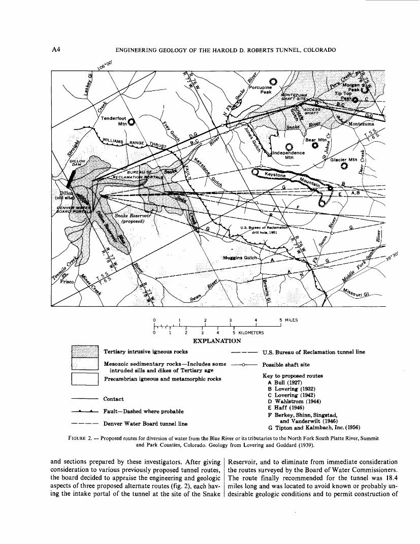
Key to proposed routes A Bull (1927) B Lovering (1932) C Lovering (1942) D Wahlstrom (1944) E Haff (1946) F Berkey, Shinn, Singstad,
and Vanderwilt (1946) G Tipton and Kalmbach, Inc. (1956)
FIGURE 2. Proposed routes for diversion of water from the Blue River or its tributaries to the North Fork South Platte River, Summit and Park Counties, Colorado. Geology from Levering and Goddard (1939).
and sections prepared by these investigators. After giving consideration to various previously proposed tunnel routes, the board decided to appraise the engineering and geologic aspects of three proposed alternate routes (fig. 2), each hav ing the intake portal of the tunnel at the site of the Snake
Reservoir, and to eliminate from immediate consideration the routes surveyed by the Board of Water Commissioners. The route finally recommended for the tunnel was 18.4 miles long and was located to avoid known or probably un desirable geologic conditions and to permit construction of

GEOLOGIC INVESTIGATIONS, ENGINEERING DESIGN, AND CONSTRUCTION METHODS A5
access shafts in Keystone Gulch and Hall Valley. The report included a geologic profile (pi. ID) and an estimate based on the available geologic information that about one-third the length of the tunnel would require no roof supports during tunnel driving, that perhaps one-tenth would require heavy supports, and that the remainder would require some sup port, ranging from heavy to light.
The engineering investigations of all aspects of diversion of waters from the drainages of the Eagle, Piney, Williams, and Blue Rivers to the eastern slope were summarized in 1948 in a comprehensive and detailed analysis prepared by the U.S. Bureau of Reclamation entitled "Blue River- South Platte Project, Colorado A Potential Transmoun- tain Project," which, in addition to the main text, included 13 appendixes. Consideration was given to the relative merits of alternate methods of water diversion and storage that would bring water to the eastern slope into headwaters of South Boulder Creek, Clear Creek, or the South Platte River. Comparison of costs and benefits clearly showed the advantages of a plan that would include a complex of canals, tunnels, and reservoirs controlling water for ter minal storage on the western slope in the Snake Reservoir. Water from the Snake Reservoir would then be transported
under the Continental Divide into the South Platte drainage through an 18-mile-long tunnel that would follow the route recommended by Berkey and his associates on the 1946 Board of Consultants.
At this stage of planning, the different ultimate objectives of the U.S. Bureau of Reclamation and the Board of Water Commissioners came into sharp focus. The Bureau of Reclamation was concerned with a regional development of water resources to obtain a maximum variety of benefits, in cluding irrigation and power development, whereas the Board of Water Commissioners was primarily concerned with a local use the immediate development of water for domestic use by a rapidly growing metropolitan area.
Although the Board of Water Commissioners had started excavation of a tunnel that followed the northern dogleg route surveyed by Wahlstrom, the Bureau of Reclamation continued its investigation of the tunnel route recommended by the Berkey Board in 1946. In January 1951 J. P. Olson, a geologist with the Bureau of Reclamation, submitted a report that summarized the results of field study along the route recommended by the U.S. Bureau of Reclamation Board of Consultants in 1946. Included also was a log of a 1,400-foot-deep exploratory drill hole in Keystone Gulch

A6 ENGINEERING GEOLOGY OF THE HAROLD D. ROBERTS TUNNEL, COLORADO
(pl.25) drilled near the site of a proposed shaft along the tunnel line, and a geologic map and section based on the U.S. Geological Survey's "Geologic Map of the Front Range Mineral Belt,"prepared by T. S. Levering and E. N. Goddard and published in 1939. Olson concluded that the information from the drill hole indicated that great dif ficulty would be experienced in sinking a shaft at the site and that such a shaft would be impractical. He urged recon sideration of the nothern dogleg route of the Board of Water Commissioners before any further geologic work along the Bureau of Reclamation route should be contemplated. Olson also suggested that the estimates of the amount of support required in the tunneling operation based on the ap praisal in the Berkey report (Berkey and others, 1946) probably were too low.
In 1955 the residents of the City and County of Denver approved a bond issue for water-works improvements that included the diversion of water from the Blue River. In the same year, long-standing litigation over the use of Blue River water was settled by a decree entered by the United States District Court for Colorado on October 12, 1955. The decree confirmed the right to divert 788 second-feet of water through the Montezuma tunnel and a storage right for 252,678 acre-feet of water for a reservoir at Dillon, as ad judicated to the city of Denver by State courts on June 24,
1946. The actions by the residents of Denver and the courts required immediate resolution of the differences of opinion as to the best method for diverting water from the Blue River to eastern slope drainages for effective use as a source of domestic water supply by the city of Denver. Tipton and Kalmbach, Inc., and Phillips, Carter, Osborne, Inc., of Denver, Consulting Engineers, were retained by the Board of Water Commissioners to make feasibility studies and to prepare plans and specifications for the tunnel (which was by now designated the Harold D. Roberts Tunnel) with as much expediency as possible.
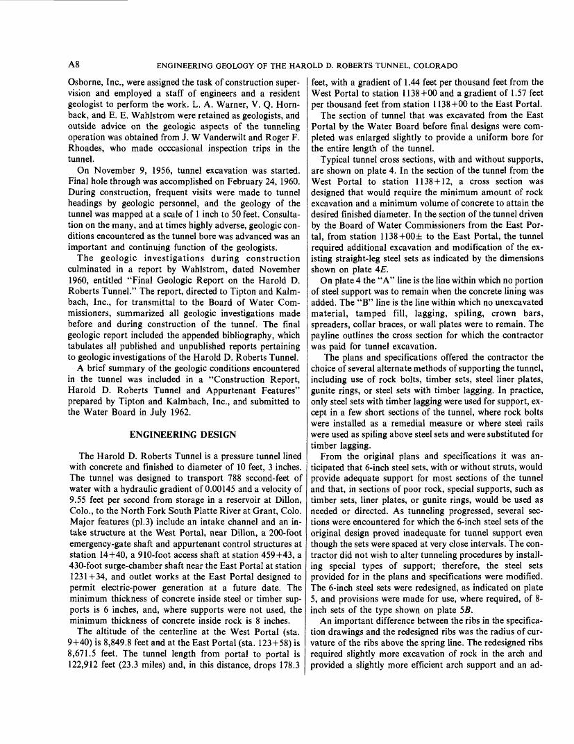
On October 15, 1955, E. E. Wahlstrom submitted a report to the Board of Water Commissioners describing the results of borings in the deep gravels that buried the west ap proach to the portal (fig. 3) of the dogleg route northeast of Dillon (old site).
On October 28, 1955, a Board of Consultants was con vened in the offices of Tipton and Kalmbach, Inc., to study the problems of Blue River water diversion. The four- member board, F. R. Purvis, C. R. Rankin, B. W. Steele, and W. R. Young, made art extensive reveiw of all problems; the review culminated in a memorandum report to Tipton and Kalmbach on January 3, 1956. In their deliberations, the members of the board assumed that any tunnel route chosen would, of necessity, take into account
(5+00) Verticalg
PLAN
'Ground water at 28 ft. Elevation, 8838.5 ft. September 1955
>9100-
9000'-
8900'-
8800'-
P7nn'-
1DO
^v^^cvcl3,:^*vlGraveK
West ^ Water table Portal, T 2
T_6 (September 1955)^^ ^ T_3\ T-l " 89i3^^-
Assumed water table-y 8gl32v\ / ag23 6\\ 8824:9x\^ \ _ u '^\--<-g^y j
s^-j*-«-^-\4J'*-»4-i«--»i-t-^---»-~X-».v--vVL-*r*-'-5ri" ̂A-»-^^ri--^^y'-r-r-.\f«-^y"^;^ ;i^s»^!!i**ll'\. M unnel
^Ts"su^TedrSdT'r"'~ 8780.2 / \Gravel \8789.6 \NBedrockN 8798.9 88d7 'u
SECTION ^Opencut E.E. Wahlstrom, 1955
0 200 400 600 800 1000 FEET 1 , , , 1 1 1 I 11 * 1 ' 1 I0 100 200 300 METERS
-9100'
-9000'
- 8800'
-8700
FIGURE 3. Plan and profile of approach to the West Portal of the Roberts Tunnel, Summit County, Colo.

GEOLOGIC INVESTIGATIONS, ENGINEERING DESIGN, AND CONSTRUCTION METHODS A7
the ultimate construction of a dam and reservoir on the Blue River near Dillon, and that accordingly, no consideration could be given to other proposals for water diversion, such as the one that would utilize storage in the Snake Reservoir, as proposed by the U.S. Bureau of Reclamation.
At the time that this Board of Consultants convened, the heading in the tunnel, being driven by the Board of Water Commissioners from the East Portal of the nothern dogleg route, had been advanced almost 10,000 lineal feet from the portal. Nevertheless, the board decided to make a thorough analysis of the feasibility of several alternate routes, engineering and geologic data were assembled from all previous studies, and conferences were held with persons who previously had worked with the numerous and complex problems of the Blue River water diversion.
Several possible locations for tunnels were considered (fig. 2), but for each proposed route it soon became ap parent that, in comparison with what was known about the geologic conditions along the northern dogleg route, the available detailed geologic information to enable reasonably safe estimates of the ease or difficulty of tunnel driving was inadequate. Available geologic information chiefly that incorporated in the 1:62,500 geologic map of the Front Range mineral belt (Lovering and Goddard, 1939) and in the Montezuma quadrangle and Breckenridge mining dis trict reports (Lovering, 1934, 1935) nevertheless made it possible to eliminate several routes from consideration because of obviously adverse geologic conditions.
Among the geologists consulted by the board were T. S. Lovering and D. J. Varnes of the U.S. Geological Survey, M. Merriman of the U.S. Bureau of Reclamation, J. W Vanderwilt of the Colorado School of Mines, and L. A. Warner and E. E. Wahlstrom from the University of Colorado and associated with the Board of Water Com missioners in its then-current geologic investigations. Merriman (1956) submitted a written report summarizing his appraisal of the geologic conditions along the northern dogleg route and the other routes being considered by the Board of Consultants. His report included a table cor relating rock types, geologic structure, and ground-water conditions with predictions of the amounts of support that might be required for the various alternate routes. His analysis indicated that about the same percentage of sup port would be required for each of four alternate routes.
Although the 1943 44 maps and sections prepared by Wahlstrom along the northern dogleg route were at a scale of 1:12,000, the geologic conditions in many areas, es pecially those buried by extensive overburden, were still un known. The Board of Consultants recommended immediate drilling of additional exploratory holes at critical accessible points along the western part of the tunnel route (pi. 2C), a segment of the route known to be of extreme geologic com plexity. Time limitations did not permit consideration of a program of drill-hole exploration along other sections of the tunnel route.
By the end of 1955 the Board of Water Commissioners had driven the tunnel 9,986 feet from the East Portal of the northern dogleg route. The tunnel passed through struc turally complex, generally competent igneous and metamorphic rocks. Surface geology over the tunnel, ahead of the tunnel heading, indicated that the tunnel would con tinue to intersect similar rocks for a distance of several miles. The Board of Consultants recommended detailed geologic mapping of the completed part of the tunnel and correlation of the geology with the rate of tunnel advance and the amount and kinds of supports that were used to ob tain experience useful in predicting the rate of progress and the needed support in similar, uncompleted sections of the tunnel.
Extensive use was made of geologic data by the contrac ting firms that prepared bids for construction of the Harold D. Roberts Tunnel. A bibliography of all geological reports was included in the plans and specifications prepared by Tipton and Kalmbach, Inc. On July 12, 1956, the contract for construction was awarded to Blue River Constructors, Inc., a combination of several contracting firms, and a Notice to Proceed was issued to the contractor on July 17, 1956. The bid was for $38,855,976.40. Final inspection of the work under the Contract for Construction was made on May 17, 1962, and acceptance was authorized by the Water Board on May 22, 1962.
Total payments to the contractor under the terms of the contract and change orders exceeded the initial bid by ap proximately 17.6 percent. Construction costs, including engineering costs, supervision, and costs of materials supplied by the Water Board averaged nearly $2.1 million per mile of tunnel.
The plans and specifications called for item-by-item bid ding for the various categories of work and for supplying of materials. Several special items, such as metering equip ment, were supplied by the Water Board. The item-by-item method of bidding reflected the uncertainties inherent in construction of a long tunnel in a region of complex geology, and it resulted in a more reasonable total bid than would have been possible if all the risks of the operation had been the sole responsibility of the contractor. The plans and specifications included estimates by the designing engineers of quantities of excavation and quantities of materials that would be required to drive, support, and complete the tunnel and appurtenant features and to maintain safety in and around them. Estimates of the kinds and quantities of sup ports, the lineal feet of feeler holes that might be required, the amount of grout that would be used in sealing off water flows, and the amounts of water that would be encountered depended to a large extent on prediction of geologic con ditions at tunnel level.
Item-by-item bidding required close supervision of all operations by representatives of the Board of Water Com missioners, so that unjustified expenditures would not be in curred. Tipton and Kalmbach, Inc., and Phillips, Carter,
A8 ENGINEERING GEOLOGY OF THE HAROLD D. ROBERTS TUNNEL, COLORADO
Osborne, Inc., were assigned the task of construction super vision and employed a staff of engineers and a resident geologist to perform the work. L. A. Warner, V. Q. Horn- back, and E. E. Wahlstrom were retained as geologists, and outside advice on the geologic aspects of the tunneling operation was obtained from J. W Vanderwilt and Roger F. Rhoades, who made occcasional inspection trips in the tunnel.
On November 9, 1956, tunnel excavation was started. Final hole through was accomplished on February 24, 1960. During construction, frequent visits were made to tunnel headings by geologic personnel, and the geology of the tunnel was mapped at a scale of 1 inch to 50 feet. Consulta tion on the many, and at times highly adverse, geologic con ditions encountered as the tunnel bore was advanced was an important and continuing function of the geologists.
The geologic investigations during construction culminated in a report by Wahlstrom, dated November 1960, entitled "Final Geologic Report on the Harold D. Roberts Tunnel." The report, directed to Tipton and Kalm- bach, Inc., for transmittal to the Board of Water Com missioners, summarized all geologic investigations made before and during construction of the tunnel. The final geologic report included the appended bibliography, which tabulates all published and unpublished reports pertaining to geologic investigations of the Harold D. Roberts Tunnel.
A brief summary of the geologic conditions encountered in the tunnel was included in a "Construction Report, Harold D. Roberts Tunnel and Appurtenant Features" prepared by Tipton and Kalmbach, Inc., and submitted to the Water Board in July 1962.
ENGINEERING DESIGN
The Harold D. Roberts Tunnel is a pressure tunnel lined with concrete and finished to diameter of 10 feet, 3 inches. The tunnel was designed to transport 788 second-feet of water with a hydraulic gradient of 0.00145 and a velocity of 9.55 feet per second from storage in a reservoir at Dillon, Colo., to the North Fork South Platte River at Grant, Colo. Major features (pi.3) include an intake channel and an in take structure at the West Portal, near Dillon, a 200-foot emergency-gate shaft and appurtenant control structures at station 14+40, a 910-foot access shaft at station 459+43, a 430-foot surge-chamber shaft near the East Portal at station 1231+34, and outlet works at the East Portal designed to permit electric-power generation at a future date. The minimum thickness of concrete inside steel or timber sup ports is 6 inches, and, where supports were not used, the minimum thickness of concrete inside rock is 8 inches.
The altitude of the centerline at the West Portal (sta. 9+40) is 8,849.8 feet and at the East Portal (sta. 123+58) is 8,671.5 feet. The tunnel length from portal to portal is 122,912 feet (23.3 miles) and, in this distance, drops 178.3
feet, with a gradient of 1.44 feet per thousand feet from the West Portal to station 1138+00 and a gradient of 1.57 feet per thousand feet from station 1138+00 to the East Portal.
The section of tunnel that was excavated from the East Portal by the Water Board before final designs were com pleted was enlarged slightly to provide a uniform bore for the entire length of the tunnel.
Typical tunnel cross sections, with and without supports, are shown on plate 4. In the section of the tunnel from the West Portal to station 1138 + 12, a cross section was designed that would require the minimum amount of rock excavation and a minimum volume of concrete to attain the desired finished diameter. In the section of the tunnel driven by the Board of Water Commissioners from the East Por tal, from station 1138+00± to the East Portal, the tunnel required additional excavation and modification of the ex isting straight-leg steel sets as indicated by the dimensions shown on plate 4E.
On plate 4 the "A" line is the line within which no portion of steel support was to remain when the concrete lining was added. The "B" line is the line within which no unexcavated material, tamped fill, lagging, spiling, crown bars, spreaders, collar braces, or wall plates were to remain. The payline outlines the cross section for which the contractor was paid for tunnel excavation.
The plans and specifications offered the contractor the choice of several alternate methods of supporting the tunnel, including use of rock bolts, timber sets, steel liner plates, gunite rings, or steel sets with timber lagging. In practice, only steel sets with timber lagging were used for support, ex cept in a few short sections of the tunnel, where rock bolts were installed as a remedial measure or where steel rails were used as spiling above steel sets and were substituted for timber lagging.
From the original plans and specifications it was an ticipated that 6-inch steel sets, with or without struts, would provide adequate support for most sections of the tunnel and that, in sections of poor rock, special supports, such as timber sets, liner plates, or gunite rings, would be used as needed or directed. As tunneling progressed, several sec tions were encountered for which the 6-inch steel sets of the original design proved inadequate for tunnel support even though the sets were spaced at very close intervals. The con tractor did not wish to alter tunneling procedures by install ing special types of support; therefore, the steel sets provided for in the plans and specifications were modified. The 6-inch steel sets were redesigned, as indicated on plate 5, and provisions were made for use, where required, of 8- inch sets of the type shown on plate 5B.
An important difference between the ribs in the specifica tion drawings and the redesigned ribs was the radius of cur vature of the ribs above the spring line. The redesigned ribs required slightly more excavation of rock in the arch and provided a slightly more efficient arch support and an ad-

GEOLOGIC INVESTIGATIONS, ENGINEERING DESIGN, AND CONSTRUCTION METHODS A9
ditional clearance that was useful during placement of the concrete lining in the tunnel.
In sections of the tunnel where the contractor excavated the tunnel to a width sufficient to permit installation of dou ble tracks and switching and storage facilities, straight-leg steel supports of the type in figure 4 were installed.
To divert water flows that could not be shut off in the tunnel by grouting, designs included provisions for tile drains below the concrete lining. Low-pressure grouting through grout holes in the concrete was used to fill any voids between concrete and rock that might result from imperfect concrete placement.
2 holes %" diam.
i/2" plate
Butt-plate detail
yz" radiusL_
_j
1*
X :£
>
j t-%
i
9'J -»
' /
/
}l"
','f ',
Foot-plate detail
FIGURE 4. Shop drawing of steel sets used by contractor at double-track switching and materials storage stations, Roberts Tunnel.

A10 ENGINEERING GEOLOGY OF THE HAROLD D. ROBERTS TUNNEL, COLORADO
CONSTRUCTION PROCEDURES
Actual tunneling was preceded by several preparatory operations. At the West Portal an open cut was excavated to the tunnel portal. The existing tunnel from the East Portal was enlarged, and the steel sets were modified. To provide two additional tunnel headings, an access shaft was sunk at station 459+43 and was lined with concrete to a circular cross section of 16-foot diameter, and a muck pocket was excavated below tunnel level. Construction and lining of the emergency-gate shaft at station 14+40 and the surge- chamber shaft at station 1231+35 were completed by inter mittent operations as the tunneling schedule permitted.
The access shaft was sunk with the aid of a shaft jumbo on which pneumatic drills were mounted. After blasting, muck was removed with an "orange-peel" loader and steel buckets. The emergency-gate shaft and the surge-chamber shaft were constructed by excavating raises from the tunnel. Shafts of full diameter were then sunk and lined from the surface downward. Muck was disposed of through the raises and hauled out of the tunnel.
Blast holes at the tunnel headings were drilled by means of four pneumatic drills mounted on a two-platform jumbo. Ordinarily a "pyramid cut" drill-hole pattern was used, with 41-52 holes drilled to a depth of 7 9 feet, and, less com monly, to a depth of 11 feet. Seven-foot rounds were loaded with 200 225 pounds of 45-percent dynamite, and 9-foot rounds were loaded with as much as 250 pounds of ex plosives. About 5 pounds of explosives were required per cubic yard of rock for proper results in hard rock. Electric primers (detonators) with delays numbered 1 through 9 or 10 were used to control the blasting sequence.
Figure 5 shows a typical drill-hole pattern used for hard rock. Many variations of the drill pattern were used, as dic tated by local conditions.
Blasted rock was loaded by means of air-powered mechanical loaders. Switching of muck cars near the tunnel heading was accomplished with the aid of a movable, double-track California switch.
In sections of the tunnel where unsafe conditions were an ticipated beyond the heading, one to several feeler holes, 25-50 feet long, were drilled from the jumbo into the heading. If water in undesirable amounts was encountered, grout was pumped into the feeler holes to refusal, or until it was estimated that maximum benefits under prevailing con ditions had been realized. At station 38+65, in the heading being driven from the West Portal, excessive flows of water were encountered, and construction of a concrete bulkhead behind the tunnel was necessary before the grouting opera tion could proceed (fig. 6A). Similarly, at station 762+88, being driven from the East Portal, large volumes of water, under a pressure of nearly 1,000 pounds per square inch, poured into the tunnel and required construction of a con crete bulkhead before an attempt could be made to pump in an adequate grout seal.
01234 FEET I'M' . ' . ', '0 1 METERS
FIGURE 5. Typical drill-hole pattern for hard ground, Roberts Tunnel. Dark circles indicate cut holes. Numbered areas include sets of holes having various functions and indicate general sequence of detonation of blast holes. Area 1, Contains converging cut holes that produce a pyramid cut, a wedge-shaped plug of rock blasted out of the tunnel heading. Blasted in three stages. Area 2, Contains reliever holes that shatter rock and direct slabs inward toward opening produced by the pyramid cut. Blasted in three stages. Area 3, Contains shape holes that determine outline of excavated section above tunnel invert. Blasted in three stages, one of which may coincide with blasting in area 4. Area 4, Contains lifters that lift and move shattered rock into tunnel opening preparatory to mucking operation. Lifters also determine shape of tunnel invert. Commonly blasted in a single stage.
The spacing and kind of steel supports installed in the tunnel required use of judgement by the inspectors at the tunnel headings. As a safety measure, supports were in stalled if there was any doubt whether rock exposed after blasting was competent and self-supporting. Several sec tions of the tunnel, especially in hydrothermally altered parts of the Montezuma stock, required the placing of ad ditional supports and the realinement of existing supports which had shifted as a result of slow movements in the in competent rocks far behind the advancing tunnel headings. Similarly, slabbing of layered rocks behind the tunnel headings was overcome by local use of rock bolts, wire screen, and gunite coatings.
In sections of very heavy rock load or in wet sections of the tunnel, the heading was advanced by use of timbered top headings (fig. 6B), use of steel rail spiling (fig. 6C), or in stallation of temporary timber bulkheads (fig. 6Z>).
The headings approaching each other in the west leg of the tunnel were holed through on January 2, 1960, to be

GEOLOGIC INVESTIGATIONS, ENGINEERING DESIGN, AND CONSTRUCTION METHODS All
FIGURE 6. Emergency support measures for very heavy ground or water conditions. A, Bulkhead installation; tunnel heading at station 38+65. Tunnel was filled with concrete to nipples of pipes (foreground) before grouting to seal off heavy water flow at heading. B, Top heading with temporary timber supports in heavy ground beyond 8-inch steel supports. Full face at station 339+44. C, Steel support failure at Station 273+50. Heavy squeezing ground has deformed 8-inch steel sets. Note rail spiling and temporary timber supports. D, Timber bulkhead holding heavy running ground at station 273+12.
followed by holing through of the east leg on February 24, 1960. Concrete lining and construction of appurtenant structures were completed in 1962. Water began to flow through the tunnel in 1964 after completion of Dillon Dam and Reservoir.
SURVEYED CONTROLS
Horizontal- and vertical-control surveys initially con sisted of a triangulation net and precise level circuits. Throughout the period of tunnel driving, a special survey party was given the responsibility of maintaining accurate vertical and horizontal controls at the tunnel headings. In
addition, survey parties working at the headings provided the line and grade at the headings immediately after each round was mucked out, and at 10-foot intervals they measured tunnel cross sections.
Bearings of the lines for the East and West Portal headings were transferred directly from the triangulation network. Bearings of lines for the two headings from the access shaft were transferred from the surface triangulation network to underground workings by plumbbob lines suspended in the access shaft. The high order of accuracy of the surveyed controls is indicated by errors of closure of 0.12 foot in alinement, 0.21 foot in grade, and 0.02 foot in

A12 ENGINEERING GEOLOGY OF THE HAROLD D. ROBERTS TUNNEL, COLORADO
stationing at the point of hole through of the west leg, and of 3.25 feet in alinement, 0.343 foot in grade, and 4.533 feet in stationing for the east leg.
GLOSSARY"A" line. The line within which no steel support or timber support shall re
main.Arch. Curved roof of an underground opening. The part of the tunnel above
the centerline.Arching tendency. Tendency of incompetent or moderately competent
rocks to form an arch above an underground opening by caving. Com monly, the arch assumes the shape of a Gothic arch in cross section.
"B" line. The line within which no unexcavated material, tamped fill, lag ging, spiling, crown bars, spreaders, collar braces, or wall plates shall re main.
Bid items. Items of work listed in contract documents and serving as the basis for bids by the contractor.
Blocking. Wood blocks placed between steel supports and walls or arch of tunnel to provide support and maintain alinement of ribs.
Breastboards. Wood planking placed temporarily at tunnel heading to con tain incompetent rock.
California switch. A section of movable double track permitting switching of muck cars near the tunnel heading.
Centerline. The line (in the Roberts Tunnel) at the center of the finished concrete lining of circular cross section.
Change order. Order issued to define procedures or items of work not covered in original contract documents, or order to change the provisions expressed in the original contract documents.
Collar brace. Wood or steel brace placed between or on top of sides of steel or timber sets to maintain alinement. Also called a "spreader."
Competent rock. Rock that stands without support in underground openings.
Contract drawings. Drawings included in the contract documents.Contract specifications. Specifications for various items of construction in
cluded in the contract documents.Crown bar. Steel rail or heavy wood plank placed on top of steel set or sets
nearest heading and projecting forward to tunnel heading. Provides tem porary support of rocks in arch until additional steel sets and lagging can be installed closer to the heading.
Extra work order. Order issued to contractor to perform work not originally described in the contract documents.
False set. A steel or timber set placed temporarily to expedite a tunneling operation; for example, a spiling operation.
Feeler hole. Hole drilled from tunnel heading or elsewhere to test geologic conditions beyond heading or in rocks adjacent to an underground open ing.
Footblock. Wood block serving as a support at the base of a steel rib. Block on which ribs are erected.
Grout. Mixture of cement, water, and, for special purposes, various ad ditives. Pumped into fractured rock to fill voids, seal off water flows, and increase strength.
Gunite. Mixture of water, sand, and cement sprayed on exposed rock to provide a protective coating.
Heading. The working face at the limit of penetration of the tunnel.Heavy ground. Squeezing, running, or caving ground requiring extra heavy
support.Incompetent rock. Rock that will not stand in underground openings
without support.Invert. The portion of the tunnel below the centerline. The bottom or floor
of a tunnel.Invert section. The section of the tunnel below the centerline or spring line.Jumbo. A movable platform on which one or more drills'are mounted.
Used primarily for drilling blast holes at the tunnel heading but may provide elevated work space for other operations.
Jump set. Steel or timber set placed between existing sets to provide ad ditional support.
Lagging. Steel plates or beams or wood planking placed above and on sides of steel ribs to contain broken rock and to prevent its fall into an un derground opening. Also acts to receive and transfer rock loads to ribs, after appropriate blocking. Spacing depends on local conditions.
Left rib. The steel rib on the left side of the tunnel as one faces the tunnel heading.
Liner plate. Preformed plain or corrugated steel plates placed behind or between ribs as tight lagging to contain bad ground, to divert water flows, and to distribute rock loads evenly to ribs.
Muck. Disaggregated rock formed by blasting operation or by the free flow of incompetent material into an underground opening.
Mucking machine. The machine used to load broken rock for haulage out of underground excavations.
Overbreak. Rock removed from outside the payline as defined in the specifications. Usually expressed as the percentage of material removed in a cross-sectional area relative to the area within the payline. Also may be expressed as a volume percent.
Payline. The line beyond which the contractor shall not be paid for excava tion. Excavation outside the payline is done at the contractor's expense.
Permanent support. The concrete lining of the tunnel. Steel and timber sup ports are regarded as temporary supports.
Popping rock. Stressed rock that fails with explosive violence and ejects large and small rock fragments at high velocity.
Pressure tunnel. A tunnel with control works at the outlet and designed to withstand, without loss or structural failure of the tunnel, water stored in the tunnel under hydrostatic head. In the Roberts Tunnel, with the outlet valves closed and Dillon Reservoir filled to capacity, the hydrostatic pressure in the tunnel near the surge-chamber shaft is equivalent to that of a standing column of water about 360 feet in height that is, about 156 psi.
Progress. A measure of the speed and efficiency with which construction of any kind proceeds.
Progress report. In the Roberts Tunnel operation, progress was reported twice each month. The report periods extended from the first to the fifteenth and from the fifteenth to the last day of each month.
Rib. A curved steel segment comprising half of a steel set or support.Right rib. The steel rib on the right side of the tunnel as one faces the tunnel
heading.Roof. The upper part of a tunnel, especially that part of the tunnel im
mediately above the centerline.Rock bolt. Steel bolt that is split at one end and inserted into drilled hole in
rock to support the rock. Head of bolt is forced against a steel plate next to the rock to make bolting action more effective.
Running ground. Clayey or sandy aggregate, usually water-saturated, that flows freely into underground excavations.
Spalling rock. A rock mass under stress that yields thin slabs or wedges of rock by rapid failure. Slabs commonly form parallel to walls or to arch of an opening in rock.
Spiling. Pointed steel bars or rails, or wood planks or logs driven into the tunnel heading to support incompetent rock until supports can be placed. Usually, the spiling is driven above and beyond the supports nearest the heading, or on top of and beyond a false set.
Spitting rock. A rock mass under stress that breaks and ejects small fragments with considerable velocity.
Spreader. Wood plank or steel beam placed between ribs to maintain ten sion on tie rods or preserve alinement. Also called "collar brace."
Spring line. The line across or parallel to the tunnel, above which the steel ribs are bent to a radius of curvature different from that below it. Longest horizontal dimension between steel ribs. May or may not coin cide with centerline.
Squeezing ground. Incompetent material, generally clayey, that behaves plastically under stress and tends to close the tunnel opening because of adjacent or superjacent loads.

GEOLOGIC INVESTIGATIONS, ENGINEERING DESIGN, AND CONSTRUCTION METHODS A13
Station. Distance from zero point measured in hundreds and fractions of feet. For example, station 105+06.5 is 10,506.5 feet from station 0+00.
Steel rib. One of the segments of bent structural steel bolted to another rib to form a steel support or steel set in the tunnel.
Steel set. Steel support consisting of two ribs bolted or welded together. May include a strut across the invert of the tunnel.
Strut. Sometimes called "invert struts" are steel or timber segments placed between steel ribs across tunnel invert to provide additional strength. Bolted, welded, or otherwise fastened to bottom extensions of ribs.
Support. Any fabricated structure, steel, wood, or concrete, placed to pre vent failure of rocks around underground openings.
Swelling ground. Rock that swells after being exposed. Usually increases in volume because of hydration of clay minerals in an altered rock.
Temporary support. Support placed to support tunnel rocks until perma nent supports can be installed. All supports except the concrete are generally regarded as temporary.
Tie rod. Steel rod threaded at both ends. Used as a connection between ad jacent steel sets to hold sets in place and provide strength in the direction of the tunnel.
Timber lagging. Timber planks placed on sides and on top of steel or timber sets to contain exposed rocks between the sets and to transmit loads to the steel sets.
Top heading. A small tunnel opening ahead of the full-size opening. Used to probe and place temporary supports in exceedingly incompetent or wet sections of tunnel.
Tunnel face. The tunnel heading.Tunnel section. Outlines of tunnel as measured at right angles to centerline.
Also, any portion of the tunnel measured parallel to the direction of the tunnel.
Tunnel supports. Wood, steel, or concrete structures placed to prevent collapse or failure of tunnel rocks.
Wall plate. Steel or timber beams of various designs placed longitudinally along sides of tunnel to act as a level support for ribs. Commonly, the wall plate serves to transmit loads from the ribs to blocks or posts with a spacing different from that of the ribs and distributes loads on ribs through the intervals between ribs.
Wedge. Wood wedge used to hold lagging or steel supports in place.Working face. The heading being excavated by drilling and blasting.
CHRONOLOGY OF STUDY REPORTS
1927, Bull, G. M., Blue River diversion: Rept. to Denver Board of Water Commissioners, unpublished.
1932, Levering, T. S., Geology of the Blue River diversion tunnel: Rept. to Denver Board of Water Commissioners, unpublished.
1932, Wilson, J. H., and Boyd, J., Report on geophysical investigations along the Blue River diversion tunnel line, Summit County, Colorado: Rept. to Denver Board of Water Commissioners, un published.
1934. Lovering, T. S,Geology and ore deposits of the Breckenridge mining district, Colorado: U.S. Geol. Survey Prof. Paper 176, 64 p.
1935. Lovering, T. S., Geology and ore deposits of the Montezumaquadrangle, Colorado: U.S. Geol. Survey Prof. Paper 178, 119 p.
1938, Lovering, T. S., and Goddard, E. N., Geologic map of the Front
Range mineral belt, Colorado: Colorado Sci. Soc. Proc., v. 14, no. 1,p. 1-48 (expl. text).
1939, Lovering, T. S., and Goddard, E. N., Geologic map of the FrontRange mineral belt: U.S. Geol. Survey Map (reissued 1950 as pi. 2 ofProf. Paper 223).
1942, Lovering, T. S., A preliminary report on alternate lines for the BlueRiver diversion tunnel between Dillon and Grant, Colorado: Rept. toDenver Board of Water Commissioners, unpublished.
1944, Wahlstrom, E. E., Proposed Blue River water diversion tunnel: Rept.to Denver Board of Water Commissioners, unpublished.
1944. Wahlstrom, E. E., Proposed Blue River water diversion tunnel, from shaft 2 to east portal No. 2: Rept. to Denver Board of Water Com missioners, unpublished.
1945. Lasson, G. D., Compilation of geologic information on proposed tunnels. Blue River South Platte project, Colorado: U.S. Bur. Reclamation, Region 7, unpublished.
1946. Haff, J. C., Geological reconnaissance report on the Montezuma tunnel: U.S. Bur. Reclamation, Region 7, unpublished.
1946, Berkey, C. P., Shinn, C. R., Singstad, Ole, and Vanderwilt, J. W, Report of the Board of Consultants appointed to investigate and select a Montezuma tunnel route, Blue River South Platte project, Colorado: U.S. Bur. Reclamation, Region 7, unpublished.
1948, Berkey, C. P., Shinn, C. R., Singstad, Ole, and Vanderwilt, J. W, Blue River South Platte project, Colorado A potential transmountain project: U.S. Bur. Reclamation, Region 7, un published.
1951, Olson, J. P., Geologic report on Montezuma tunnel route and Keystone Gulch shaft site, Blue River-South Platte project, Colorado: U.S. Bur. Reclamation, Region 7, unpublished.
1955, Wahlstrom, E. E., Investigation of approach to west portal of the Blue River tunnel: Rept. to Denver Board of Water Commissioners, unpublished..
1955. Wahlstrom, E. E., and Warner, L. A., Geologic map and report, Harold D. Roberts Tunnel, station 1143+60 to east portal: Rept. to Denver Board of Water Commissioners, unpublished.
1956. Purvis, F. R., Rankin, C. R., Steele, B. W., and Young, W. R., Memorandum report to Tipton and Kalmbach, Inc., on the Harold D. Roberts Tunnel: Board of Consultants, unpublished.
1956, Merriman, M., Untitled report to Tipton and Kalmbach, Inc.: un published.
1956, Purvis, F. R., Rankin, C. R., Steele, B. W., and Young, W. R., Report to Tipton and Kalmbach, Inc., on the Harold D. Roberts Tunnel: unpublished.
1956, Wahlstrom, E. E., Harold D. Roberts Tunnel, station 159+46 to Angle Point 2: Rept. to Denver Board of Water Commissioners, un published.
1956, Tipton and Kalmbach, Inc., Contract documents including specifications and drawings for construction of Harold D. Roberts Tunnel and appurtenant features in Summit and Park Counties, Colorado: City and County of Denver, Board of Water Com missioners.
I960, Wahlstrom, E. E., Final geologic report on the Harold D. Roberts Tunnel: Rept. to Tipton and Kalmbach, Inc., unpublished.
* U.S. GOVERNMENT PRINTING OFFICE: 1974 S43 SS1/33