historic lake park arch bridge over ravine road - in-depth
TRANSCRIPT

HISTORIC LAKE PARK ARCH BRIDGE OVER RAVINE ROAD IN-DEPTH INSPECTION REPORT
Structure P-40-576 Milwaukee County Project Number P484-15619 Prepared for MILWAUKEE COUNTY DEPARTMENT OF ARCHITECTURE AND ENGINEERING 633 W. Wisconsin Ave., Suite 1000 Milwaukee, Wisconsin 53203 July, 2015 Prepared by
One Honey Creek Corporate Center 125 South 84th Street, Suite 401 Milwaukee, WI 53214-1470 Telephone: (414) 259-1500 www.GRAEF-USA.com GRAEF Project No. 2015-0032.00

Lake Park Arch Bridge over Ravine Road In-Depth Inspection Report
Milwaukee County Project Number P484-15619
GRAEF Project No. 2015-0032.00
Prepared for: Milwaukee County
Department of Architecture and Engineering Site Address: Lake Park Arch Bridge over Ravine Road
Structure P-40-576 Prepared By: GRAEF
One Honey Creek Corporate Center 125 South 84th Street, Suite 401 Milwaukee, WI 53214-1470
(414) 259-1500
Malas Engineering, LLC W148 N6912 Terriwood Dr. Menomonee, Falls WI 53051
(414) 870-3112

TABLE OF CONTENTS
Milwaukee County Project Number P484-15619
GRAEF Project No. 2015-0032.00
1. EXECUTIVE SUMMARY .......................................................................................................... 1 2. INTRODUCTION AND BACKGROUND .................................................................................... 3
2.1. Construction History ........................................................................................................... 3 2.2. Load Rating ....................................................................................................................... 4 2.3. Previous Inspections .......................................................................................................... 5 2.4. Current In-Depth Inspection ............................................................................................... 6
3. FIELD FINDINGS ...................................................................................................................... 6 3.1. Inspection Methods ............................................................................................................ 7 3.2. Arch Ribs ........................................................................................................................... 8
3.2.1. Concrete Patches, Delaminations and Spalls.............................................................. 8 3.2.2. Cracks ...................................................................................................................... 11
3.3. Spandrels ........................................................................................................................ 13 3.3.1. Concrete Patches, Delaminations and Spalls............................................................ 13 3.3.2. Cracks ...................................................................................................................... 15
3.4. Superstructure Diaphragms and Struts ............................................................................ 18 3.5. Deck ................................................................................................................................ 19
3.5.1. Top Side ................................................................................................................... 20 3.5.2. Soffit ......................................................................................................................... 20
3.6. Abutment Thrust Blocks ................................................................................................... 24 3.7. Vaulted Abutment Walls and Wingwalls ........................................................................... 26
3.7.1. Exterior ..................................................................................................................... 26 3.7.2. Interior of the Vaulted Abutments .............................................................................. 32
3.8. Parapets .......................................................................................................................... 37 3.9. Open Expansion Joints .................................................................................................... 39 3.10. Downspouts ................................................................................................................. 40 3.11. Site Drainage ............................................................................................................... 41
4. MATERIAL TESTING.............................................................................................................. 43 4.1. Concrete Compression Testing ........................................................................................ 43 4.2. Concrete Imaging Radar Scanning .................................................................................. 44 4.3. Impact Echo Concrete Integrity Testing ........................................................................... 44 4.4. Asbestos .......................................................................................................................... 45
5. SURVEY ................................................................................................................................. 45 6. LOAD RATINGS ..................................................................................................................... 45
6.1. Materials .......................................................................................................................... 46 6.2. Modeling .......................................................................................................................... 46 6.3. Rating Analysis ................................................................................................................ 47
6.3.1. Arch Ribs .................................................................................................................. 47 6.3.2. Spandrel ................................................................................................................... 47 6.3.3. Deck ......................................................................................................................... 48 6.3.4. Load Rating Summary .............................................................................................. 48
7. CONCLUSIONS ...................................................................................................................... 48 7.1. Superstructure ................................................................................................................. 48
7.1.1. Arch Ribs .................................................................................................................. 49 7.1.2. Spandrels ................................................................................................................. 49 7.1.3. Deck ......................................................................................................................... 49 7.1.4. Diaphragms and Struts ............................................................................................. 49 7.1.5. Parapets and Downspouts ........................................................................................ 50
7.2. Substructure .................................................................................................................... 50

7.2.1. Thrust Blocks ............................................................................................................ 50 7.2.2. Abutment and Wingwalls .......................................................................................... 50
7.3. Survey ............................................................................................................................. 51 8. RECOMMENDATIONS ........................................................................................................... 52
8.1. Reopening the Bridge and Short Term Maintenance ........................................................ 52 8.2. Rehabilitation ................................................................................................................... 53
8.2.1. Structure Rehabilitation ............................................................................................. 53 8.2.2. Site Rehabilitation ..................................................................................................... 55
8.3. Replacement .................................................................................................................... 55 8.3.1. Reinforced Concrete Arch ......................................................................................... 55 8.3.2. Prefabricated Steel Truss.......................................................................................... 55 8.3.3. Prestressed Concrete Girders ................................................................................... 57
8.4. Estimated Construction Costs .......................................................................................... 58 8.4.1. Rehabilitation ............................................................................................................ 58 8.4.2. Replacement............................................................................................................. 59 8.4.3. Construction Cost Estimate Summary....................................................................... 60
I. APPENDIX B – CONCRETE TESTING REPORT ................................................................... 69 II. APPENDIX C – AESBESTOS REPORT ................................................................................. 97 III. APPENDIX D – SURVEY DATA ........................................................................................... 100 IV. APPENDIX E – ESTIMATED CONSTRUCTION COSTS ..................................................... 101

1. EXECUTIVE SUMMARY To further investigate bridge deterioration noted in a September 2014 inspection and a
follow-up December 2014 inspection, an arm’s length In-Depth Inspection of Lake Park’s concrete
arch bridge over Ravine Road was performed between March 9 and March 27, 2015. The bridge is
a 118 ft long open spandrel reinforced concrete arch structure constructed in 1905/1906. It is
comprised of reinforced concrete arch ribs, open spandrels, deck, parapets, and vaulted abutments.
The bridge carries pedestrian, bicycle, and occasional light maintenance vehicles, but has been
closed to traffic on and below due to advanced deterioration since the December 2014 inspection.
Field findings – earlier rehabilitation efforts which had been conducted on the bridge at an
unknown time include bridge rail replacement, concrete surface repair, and crack routing/caulking.
Most existing concrete patches on the arch ribs and spandrels are tightly adhered to the base
concrete. Concrete delaminations and spalls were most prevalent on the west arch and appear to
have occurred at previous concrete patches. Caulk in the routed cracks appears cracked and loose
in some places. Many concrete patches on the deck underside have spalled off and other patches
are delaminated.
Local failures have occurred at the northeast and southeast wingwalls of the north and south
abutments. Advanced slope erosion at the southeast wingwall has caused footing undermining with
resulting 3” of settlement and rotation resulting in 8” of horizontal movement. At the northeast
wingwall, 1” of settlement and rotation resulting in 5” of horizontal movement has occurred, but
without evidence of erosion. The northwest and southwest wingwalls exhibit lesser degrees of
movement. Extensive soil erosion inside of the south vaulted abutment is occurring.
Milwaukee County survey crews have been monitoring the edge of deck elevations. After 3
cycles of shots, it appears that over its lifetime the main span has experienced minor west side
settlement resulting in a slight rotation. Load ratings – concrete cores taken at the abutment thrust blocks were used to establish
the existing concrete strength. This strength was used in load rating calculations to determine
structural pedestrian and maintenance vehicle live load capacities of the arch ribs, spandrel, and
deck elements. The resulting load ratings indicate that the arch ribs have adequate capacity to
resist current code prescribed pedestrian and maintenance vehicle loads. The spandrels and deck
do not have adequate capacity. Each has capacity to resist 44% of current code prescribed
pedestrian loads. The spandrels can only resist 20%, and the deck can only resist 30% of the
current code prescribed maintenance vehicle loads.
Conclusions and recommendations – Reopening Ravine Road and the pedestrian trail
below the bridge should only be allowed after loose concrete delamination removal occurs on the
superstructure and deck elements. The pathway on the bridge can be opened up to pedestrians
1

and bicyclists only as long as surveys continue to monitor for abutment settlements. Excessive
settlements would be cause for bridge closure to all path users.
Light reinforcement, general deterioration, local failures, and inadequate live load capacities
suggest that the bridge has reached the end of its useful life. The historic nature of this structure
may warrant rehabilitation of as many elements as possible. Since many members are
inadequately reinforced, are deteriorated, and have experienced local failures, our first option is to
rehabilitate the arch ribs, spandrels, diaphragms, struts, and thrust block elements. The remaining
deck, railing, and abutment elements should be removed and replaced. If this approach is chosen,
it must be understood that the rehabilitated arch rib, spandrel, and thrust block elements may only
have a remaining estimated life of 15 to 25 years – future replacement will require deck, railing, and
partial abutment removal and replacement.
In-kind replacement of the entire bridge using modern materials and design provisions is a
second option where the architectural features of a new bridge will match those of the original
design. A third option is to replace the entire bridge with a longer span steel prefabricated truss
bridge. A fourth option is to replace the entire bridge with a longer span prestressed concrete girder
bridge with optional decorative precast concrete panels attached to the sides. All elements of a
new bridge would have an estimated life of 75 years. Construction cost estimates – for planning purposes, estimated construction costs of the
four options are:
1. Bridge rehabilitation option - $1.8 million. This cost estimate does not include future repairs
or replacement in 25 years.
2. Bridge replacement in-kind - $2.6 million.
3. Bridge replacement with a steel prefabricated truss - $1.6 million.
4. Bridge replacement with prestressed concrete girders:
a. $1.5 million with decorative panels.
b. $1.4 million without decorative panels.
2

2. INTRODUCTION AND BACKGROUND
2.1. Construction History
The Lake Park arch bridge conveys recreational, pedestrian, and park service
vehicle traffic between the bluffs adjacent to Ravine Road. It was designed in the early
1900s by Ferry & Clas, a Wisconsin architectural firm. George Bowman Ferry and Alfred
Charles Clas were partners and designed many buildings and structures listed on the
National Register of Historic Places, including this bridge. The bridge was constructed by
Newton Engineering Co., and the original plans suggest construction occurred around
1905/1906. It is located in the Milwaukee County’s Historic Lake Park, designed by
renowned Landscape Architect Frederick Law Olmsted in the late 19th Century.
This reinforced concrete arch bridge spans 118-ft spring line to spring line.
Specifically, it is an open spandrel type arch with two arch ribs spaced 13-ft apart and a rise
of 18-ft. Vaulted abutments are located at the north and south ends of the arch. Each
abutment incorporates a solid concrete thrust block to resist arch rib forces at the spring line,
as well as strip footings supporting the vaulted abutments walls. The spandrels, full depth
diaphragms between the arch ribs, and vaulted abutment walls support two-way concrete
deck slabs. Solid concrete parapets are 3’-8” tall and allow for a 12’-5” clear deck width
between the inside faces. Approaches to the bridge are asphalt.
The early proprietary Kahn system of reinforcing steel is used to reinforce the arch
ribs, spandrels, and deck in the transverse direction. One-quarter inch diameter rods
reinforce the vaulted abutment walls and deck in the longitudinal direction.
3

Figure 1: Apparent original construction photo (retrieved from the 1913 Kahn Building
Products catalog)
Though the timeline is uncertain, reconfigurations and rehabilitations have taken
place during its lifetime. This work includes:
• Replacement of the original open baluster parapets with solid concrete
parapet railings
• Removal of the steel lateral bracing between the arch ribs
• Concrete patching on the arch ribs and spandrels
• Concrete surface repair at the thrust blocks
• Downspout installation
• Routing/caulk sealing of cracks on the exterior surfaces of all bridge
elements
• Addition of a concrete overlay over the abutment deck slabs
2.2. Load Rating
In 2005, Milwaukee County contracted with GRAEF (dba Graef, Anhalt, Schloemer)
to perform a load rating analysis of the bridge. Though the original plans indicated an 80
lb/ft2 live load, an H-5 (10 kip) vehicle was used to establish the load ratings to mimic a
maintenance vehicle moving over the structure. The load ratings were completed according
4

to AASHTO load factor procedures. Only the arch rib and deck elements were load rated.
The bridge was load rated using “as new” conditions with no material deterioration assumed.
For the arch ribs, the resulting governing inventory rating was H-8, and the governing
operating rating was H-13. The arch rib ratings were controlled by element bending at the
abutments/thrust blocks.
The deck inventory rating was H-1 and the operating rating was H-2. As the deck
ratings were the lowest, this element controlled the vehicle live load capacity of the bridge.
It was not investigated at that time if the bridge had the capacity to resist the 80 lb/ft2 live
load called for on the original drawings. It was recommended at that time to restrict live
loading to light park maintenance vehicles or occasional police cars or business owner cars.
Further, strengthening the deck was recommended for any future rehabilitation projects.
2.3. Previous Inspections
Review of the WisDOT Highway Structures Information site indicates that Routine
Inspections have been conducted on this bridge at 2-year intervals from 1998 to 2010, and
Interim Inspections took place in 2004 and 2011. The 2011 Interim Inspection report rated
elements for this structure as being fair (deck) to poor (substructure and superstructure) with
spalled concrete and slope erosion being the primary areas of concern.
A Structural Safety Inspection report was submitted by K. Singh & Associates, Inc. (a
sub-consultant to Collins Engineering) in September 2014. Narrative from this report
indicated element conditions of poor (deck), serious (superstructure) and critical
(substructure). Issues raised include:
• Extensive spalling of the deck, arch ribs, and spandrel elements
• Abutment foundation settling which has caused cracks in several elements.
Several of these cracks were reported to be wide and transversely displaced
• Flexural forces in the arch being transferred into the parapet railing
• Substructure settlement causing water ponding on the deck surface
• Erosion of the embankments/side slopes around the vaulted abutments and
compromising the abutment’s integrity
Recommendations included closing the bridge to traffic, installation of a netting system to
prevent spalled concrete from falling onto the roadway below, clearing snow from the deck,
clearing and grubbing to allow for geotextile fabric installation on the side slopes, and
redirection of storm water away from the abutments. A final recommendation for structure
removal was offered due to concerns of future bridge instability. 5

2.4. Current In-Depth Inspection
Results of the Structural Safety Inspection report by K. Singh and Associates
prompted Milwaukee County to obtain a second engineering opinion by Malas Engineering
in December, 2014. Following a site visit, Malas Engineering recommended that the bridge
and Ravine Road be closed immediately. Reopening the bridge was dependent on
conducting an In-Depth Inspection of the bridge, computing a new load rating, and obtaining
recommendations for rehabilitation or replacement. In addition, it was recommended that
Milwaukee County surveyors monitor the bridge for signs of vertical movement.
3. FIELD FINDINGS The following subsections outline the material conditions of the bridge’s primary load
carrying members including the arch ribs, spandrels, deck, octagonal shaped vaulted abutment,
wingwalls, and abutment thrust blocks. Findings of the bridge secondary elements, which include
the diaphragms, struts and parapets, are also provided. See Figure 2 for a definition of these
elements.
This report is based on the conditions of the structure that were readily observable at the
time of assessment. Nondestructive and destructive testing was only performed at specific areas of
concern. Our observations were intended to be an assessment of the visible elements of the
structure from areas accessible as described throughout the report.
This report is intended to inventory existing conditions of the observed areas in the winter of
2014-2015, and to provide general recommendations for repair. Conditions observed on the date of
assessment may change if noted deficiencies are not corrected.
Figure 2: Bridge Elements
6

3.1. Inspection Methods
Both visual “from the ground” and In-Depth Inspection techniques were used for this
structure. An In-Depth Inspection is defined as an arm’s length, up close visual inspection
of structure elements to identify deficiencies not readily detectible from the ground. This
method was used for the arch ribs, spandrels, deck underside, and other elements not
readily accessible without specialized equipment. Visual inspection was used for the
remaining elements such as the parapet outside faces and high portions of the abutments.
Present at each inspection was a two-person crew consisting of either two WisDOT certified
bridge inspectors or a certified bridge inspector and an assistant. Access to the arch
underside was provided with an 80-ft aerial lift, and a ladder was used to reach openings
allowing entry into the vaulted abutment.
On the bridge arch ribs and spandrels, surfaces of these concrete superstructure
elements were visually inspected for defects such as cracks, delaminations, spalls, and
loose concrete patches. In addition, hammer tapping was performed on all surfaces of
these elements to detect delaminations and check the soundness of concrete patches.
Concrete impact echo nondestructive testing was also performed to estimate the thickness
of delaminations and loose concrete patches, as well as to spot check surfaces appearing
sound for deeper flaws.
The remaining concrete surfaces were primarily visually inspected with limited
hammer tapping used to spot check suspect areas for delaminations. Hammer tapping was
also used to remove loose delaminations that were observed on the underside of the deck
over the north hiking path. Some delaminations were also removed over the roadway. Not
all delaminations were removed, as many were tightly adhered and would be best removed
by a contractor with the proper equipment.
Concrete deterioration was documented using sketches and photos. Several crack
widths were measured, marked onto the concrete, and recorded in our field notes.
Quantities of spalls and delaminations were visually estimated. An overall view of these
findings can be seen in Appendix A.
7

3.2. Arch Ribs
The arch ribs are in fair to poor condition. Existing concrete patches indicate earlier
rehabilitation work, and many of these patches are still sound. Existing spalls and moderate
steel section loss of the exposed rebars have slightly reduced the elements’ structural
capacity.
Review of the original design drawings, and verification in the field, reveals that each
arch rib is reinforced with four 1” x 3” Kahn bars (one in each corner). In addition, two 1”
diameter Trusscon bars (one each top and bottom) are placed between the spring line and
panel points 1 and 5, changing to two ¾” diameter Trusscon bars between panel points 1 to
2 and 4 to 5. Previous rehabilitation work includes patching spalls with concrete and
applying a skim coat of a cementitious material over many surfaces to seal narrow cracks
and improve the aesthetics.
3.2.1. Concrete Patches, Delaminations and Spalls
Both arch ribs contain many concrete patches. These earlier repairs are
present along approximately 75% of the length of the rib soffits (bottom surfaces,
Figure 3). Patches are also common on the rib soffit at all four spring lines (Figure
4). The soffit patches were apparently needed to fix spalls that had occurred at the
lower corners. The rib backs (top surfaces) are exposed only along the circular and
teardrop shaped spandrel openings, and patches exist along about 50% of the
length of these surfaces. Fewer concrete patches were found on the rib vertical
surfaces. Most were located near the arch crown between panel points 2 to 4 on the
inside faces (Figure 5).
Figure 3: Concrete patches on east arch rib soffit
8

Figure 4: Concrete patches on arch rib soffits at the north spring line.
Figure 5: Concrete patches on east arch rib inside vertical face near the crown
Delaminations and spalls were most prevalent on the west rib (Figures 6 and
7):
• 3 soffit delaminations totaling 10 ft2 • 10 soffit spalls totaling 48 ft2 • 2 back spalls on the rib back totaling 16 ft2 at the north teardrop
spandrel opening • 1 spall on the inside vertical face totaling 4 ft2
Along the east rib there were:
• 5 soffit delaminations totaling 19 ft2
9

• 4 soffit spalls totaling 5 ft2 • 1 delamination on the outside vertical face totaling 4 ft2 • 2 spalls on the outside vertical face totaling 5 ft2 • 3 delamination on the inside vertical face totaling 13 ft2 • 2 spalls on the inside vertical face totaling 5 ft2
Figure 6: West arch rib soffit with spalls and exposed reinforcing steel
Figure 7: West arch rib spall with exposed Kahn bar reinforcement (note the bent up shear reinforcement)
10

When hammer tapped, most of the patches sounded well adhered to the
base concrete, suggesting thick patches that encapsulate the reinforcing steel.
Approximately 10% to 20% of the patches sounded hollow when tapped, indicating
debonding from the base concrete and possibly no encapsulation of the reinforcing
steel.
3.2.2. Cracks
The arch ribs contain a few routed/caulked cracks, generally concentrated
near the spring line (Figure 8). It is believed most of the routed/caulked cracks are at
concrete cold joints. The cold joints were formed at concrete lift boundaries when
new concrete was placed against cured concrete during the original construction.
Most of the caulk is cracked, loose or missing and is ineffective in sealing out water.
Figure 8: East arch rib north spring line with routed/caulked cracks
Several unsealed longitudinal hairline (<0.012”) to narrow (0.012” to 0.05”) to
medium (0.05” to 0.1”) cracks occur along the arch ribs. The cracks generally occur
randomly along the length of each arch. Cracks on the rib soffits typically occur at
the existing concrete patches (Figure 9). Though most were scattered, there was
some consistency of the longitudinal crack location on the rib vertical surfaces
between panel points 1 and 2. These occurred on both vertical faces of the west rib,
and on the inside vertical face of the east rib (Figure 10). Very few transverse cracks
were noted. Three were located on the east rib and two on the west rib.
11

Figure 9: West arch rib soffit with unsealed 0.040" longitudinal crack in concrete patch
Figure 10: East arch rib inside face with unsealed 0.080” longitudinal crack near the top
Map cracks occur near the spring lines of all arch ribs. These map cracks
coincide with concrete patches found on the rib soffits.
Four unsealed cracks were measured on the east arch. These ranged from
0.02” to 0.08” wide. Four unsealed cracks were measured on the west arch which
ranged from 0.01” to 0.07” wide. On the west arch rib between panel points 1 and 2,
12

a narrow longitudinal crack is present approximately mid-height on both the east and
west faces. This could be indicative of a through thickness crack. It was measured
at 0.01” thick on the west face. See Appendix A for the crack locations, and where
applicable, the width measurement.
3.3. Spandrels
The spandrels are in fair to poor condition. Existing concrete patches indicate earlier
rehabilitation work, and many of these patches are still sound. Existing spalls and steel
section loss of the exposed rebars have reduced the southeast spandrel’s structural
capacity.
The top longitudinal member of each spandrel is reinforced with one ¾” x 2” Kahn
bar along the bottom surface above the circular spandrel openings (panel points 0 to 1 and
5 to 6). Above the teardrop shaped openings (panel points 1 to 2 and 4 to 5), two 1” x 3”
Kahn bars are placed along the bottom surface to reinforce the longitudinal member.
Previous rehabilitation work includes patching spalls with concrete and applying a skim coat
of a cementitious material over many surfaces to seal narrow cracks and improve the
aesthetics.
3.3.1. Concrete Patches, Delaminations and Spalls
The spandrels above both arch ribs contain several concrete patches. On
the exterior surfaces, patches are common at the tip of the teardrop shaped
openings. Patches also occur along the concrete cold joints between the spandrel
openings (Figure 11). On the east spandrel, patches exist just underneath the deck
overhang between panel points 2 and 4 for about 50% of this length.
13

Figure 11: Concrete patch at east spandrel outside face
On the spandrel interior surfaces, patches tend to be concentrated near the
deck between panel points 2 and 4. A full length patch runs along the bottom of the
longitudinal member above the teardrop opening between panel points 1 and 2 of
the west arch.
Along the east spandrel there were:
• 2 delaminations on the outside vertical face totaling 8 ft2
• 1 spall on the outside vertical face totaling 3 ft2
• 1 spall on the inside vertical face totaling 4 ft2
In addition, the east spandrel between panel points1 and 2 has a long spall
with exposed reinforcing steel (Figure 12). It is approximately 10’ long and located
on the longitudinal member underside above the teardrop shaped spandrel opening.
Several pieces of loose concrete were removed during the inspection. There were 6
delaminations and 3 spalls noted on the remainder of the spandrels. Four of these
defects occur at concrete patches.
Along the west spandrel there were:
• 3 delaminations on the outside vertical face totaling 19 ft2
See Appendix A for locations of the delaminations and spalls.
14

Figure 12: Large spall at east spandrel opening with exposed Kahn bar reinforcing steel
When hammer tapped, most of the patches sounded well adhered to the
base concrete, suggesting thick patches that encapsulate the reinforcing steel.
Approximately 10% of the patches sounded hollow when tapped, indicating
debonding from the base concrete and possibly no encapsulation of the reinforcing
steel.
3.3.2. Cracks
The spandrels contain many routed/caulked cracks. It is believed the
majority of these routed/caulked cracks occur at concrete cold joints. Most of the
caulk is cracked, loose or missing and is ineffective in sealing out water. These
cracks are common around the circular spandrel openings between panel points 0 to
1 and 5 to 6 (Figure 13). The cracks typically reflect completely through the spandrel
wall thickness. Other typical crack locations are near the top of the spandrel inside
and outside faces where the spandrel/deck slab cold joint exists (Figure 14).
Between panel points 2 and 5 of the east spandrel, about 33% of the spandrel/deck
slab interface is caulked. Near the arch spring lines, routed/caulked cracks follow
the rib back/spandrel interface on the east and west rib exterior vertical surfaces.
15

Figure 13: East spandrel routed/caulked cracks
Figure 14: East spandrel routed/caulked crack between top of spandrel and deck
Several unsealed hairline (<0.012”) to wide (> 0.1”) cracks occur on the
spandrels. These cracks occur around the circular spandrel openings between panel
points 0 to 1 and 5 to 6, and typically reflect completely through the spandrel wall
thickness (Figures 15 and 16). Near the arch spring lines, cracks coinciding with
concrete patches follow the east and west rib back/spandrel interface on the inside
surface between panel points 0 and 1. On the outside faces of the east and west
spandrel andbetween panel points 2 and 3, a 1/8” wide crack exists between the
spandrel top and deck underside. On the spandrel inside faces, unsealed cracks are
sporadically located near the spandrel/deck slab interface.
16

Figure 15: West spandrel with unsealed 0.070" longitudinal crack between spandrel and arch rib
Figure 16: West spandrel south end with unsealed 0.030" crack in concrete patch between openings
Four unsealed cracks were measured on the east arch. These ranged from
0.05” to 3\16” wide. The 3/16” wide crack is located between the spandrel openings
at panel point 1. Six unsealed cracks were measured on the west arch which ranged
from 0.01” to 1/8” wide. Two 1/8” wide cracks were present at the circular spandrel
opening between panel points 0 and 1. See Appendix A for the crack locations, and
where applicable, the width measurement.
17

3.4. Superstructure Diaphragms and Struts
The diaphragms and struts are in good to fair condition. Full depth concrete
diaphragms are present between the east and west arch ribs/ spandrels at panel points 1, 2,
3, 4, and 5. Concrete struts between only the east and west arch ribs are present at panel
points 1.5, 2.5, 3.5, and 4.5. Both of these secondary superstructure elements serve to
provide lateral stability to the arch ribs and spandrels, and lateral wind load resistance to the
bridge. As barely seen in the photograph of Figure 1, evidence of the original lower lateral
steel bracing angles were present after the structure was built. These steel angles,
connected directly to the bottom ledge of the arch, were used to provide lateral stability
directly to the arch ribs. Since their removal, the concrete diaphragms, struts, and deck
provide the structure’s lateral bracing.
The diaphragms contain many routed/caulked cracks. It is believed the majority of
these routed/caulked cracks occur at concrete cold joints (Figure 17). Earlier rehabilitation
work also includes several concrete patches to both the diaphragms and struts. The
patches generally occur at the bottom corners of these elements, and in some cases along
the entire bottom edge. Patches were noted on all diaphragms and all struts except for strut
3.5.
Figure 17: Diaphragm at panel point 5 with routed/caulked cracks at concrete cold joints
18

Spalls are present on several of the secondary members, typically along the bottom
edges or bottom corners (Figure 18). Members containing spalls include diaphragms 3 and
4, and struts 1.5, 2.5, and 3.5.
Figure 18: Concrete patches and spalls on the crown diaphragm at panel point 3
3.5. Deck
The deck elements over the superstructure and substructure units are in poor
condition. Existing concrete surface patches on the deck underside indicate earlier
rehabilitation work, though many of the patches have debonded or spalled off. Newer
delaminations and spalls also exist. Steel section loss of the exposed reinforcing steel has
reduced the deck’s structural capacity.
The original 6” thick concrete deck is supported on 4 edges at each bay of the
superstructure. Specifically, the spandrels support the deck’s east and west edges while
diaphragms at each panel point support the north and south edges. Review of the original
design drawings reveals that the deck is reinforced with ½” x 1-½” Kahn bars spaced at 18”
on center in the east-west direction, and ¼” diameter rods spaced at 18” on center in the
north-south direction.
Over the abutments and wingwalls (collectively with the arch thrust block the
“substructure”), the deck is supported along two edges only. At the abutments, 12” x 17”
beams in line with the arch ribs support the east and west edges, whereas the wingwalls
themselves support the deck. Reinforcement is the same as that on the superstructure.
Previous deck rehabilitation work includes placing a concrete overlay over the
substructure. A 6-ft long concrete transition ramp was placed on the first bay between panel
points 0 to 1 and 5 to 6. It is unknown if an overlay had ever been placed on the
superstructure deck. 19

3.5.1. Top Side
Regular transverse cracks are present along the bridge length between panel
points 0 to 6, spaced at about 4’ on center. Approximately half of these cracks have
been previously routed/caulked, with the remainder being unsealed narrow cracks.
Only four spalls are present on the top surface, and three areas of scaling were
noted (Figure 19).
Figure 19: Small spalls on top of deck and typical cracks
Over the substructure units, the deck top side is in good condition. Between
the south end wingwalls, two transverse routed/caulked cracks and one unsealed
transverse crack are present. Between the north end wingwalls, four unsealed
transverse cracks are present along with one spall on the top surface.
3.5.2. Soffit
Along the bridge length between panel points 0 to 6, concrete patches
indicate earlier rehabilitation work. Some of these patches have spalled or
delaminated from the base concrete (Figures 20 and 21). In addition, newer
delaminations and spalls also exist (Figure 22). The spalls have exposed the deck’s
bottom mat of reinforcing steel which exhibits laminate rust.
Total quantity of spalls over the superstructure is approximately 225 ft2.
Spalls are extensive between panel points 1 to 2, 3 to 4, and 5 to 6, or 50% of the
deck panels. The panel between points 5 to 6 is located over a pedestrian hiking
path and contains a large region of delaminated concrete as well. Loose
delaminations in this bay were removed where possible during the inspection but
other more tightly adhered delaminations remain. About 105 ft2 of spalls were noted 20

between panel points 2 and 4. See Appendix A for the crack and defect locations on
the deck top side.
Figure 20: Deck soffit concrete patch and spalls with exposed Kahn bar reinforcement between panel points 1 and 2
Figure 21: Deck soffit with spalled concrete patch and exposed Kahn bar reinforcement
21

Figure 22: Deck soffit with spalled concrete patch and exposed Kahn bar reinforcement between panel points 3 and 4
Over the substructure units, as inspected from the inside the vaulted
abutments, the deck underside has spalls with exposed reinforcing steel (Figures 23
to 26). With one exception, there does not seem to have been prior rehabilitation
work performed, likely due to access difficulties. The one exception occurs at the
north octagonal vaulted abutment where about a 3’ x 3’ area of leave-in-place form
work was found, possibly to repair full depth deterioration.
Figure 23: Deck soffit spall with exposed Kahn bar reinforcement between the wingwalls of the south abutment
22

Figure 24: Deck soffit condition within the octagonal region of the south vaulted abutment
Figure 25: Deck soffit spalls with exposed Kahn bar reinforcement between the wingwalls of the north abutment
23

Figure 26: Deck soffit spalls with exposed Kahn bar reinforcement within the octagonal region of the north vaulted abutment
Total quantity of spalls over the substructure units is approximately 200 ft2.
About 120 ft2 occurs at the south vaulted abutment and wingwalls. There is about an
8’ x 10’ spall at the deck’s extreme south end between the wingwall tips. At the north
vaulted abutment and wingwalls, about 80 ft2 of spalls exist. There is also a region
of exposed reinforcing steel at the north half of the octagonal shaped vaulted
abutment, likely due to insufficient concrete cover. See Appendix A for the crack and
defect locations on the deck soffit.
3.6. Abutment Thrust Blocks
The abutment thrust blocks are in fair condition. The thrust block is a solid mass of
concrete used as the shallow foundation for the superstructure. It delivers the vertical
gravity loads and horizontal arch thrust loads into the surrounding soil, controlling the
superstructure vertical settlement and arch rib spreading. Each thrust block is
approximately 10’ H x 16’ L x 24’ W and was originally designed without reinforcing steel.
Existing concrete surface patches indicate earlier rehabilitation work. As measured
through concrete cores, patch thicknesses of the north thrust block are approximately 6”
between the arch ribs, 2” on the west side and 3” on the east side. Patch thicknesses of the
north thrust block are approximately 12” between the arch ribs, 9” on the west side and 6”
on the east side.
The surface patches appear to be reinforced with welded wire fabric. The surfaces
have extensive shrinkage cracks and are debonding from the base concrete. The north
thrust block concrete facing has wide and extensive map cracks (Figure 27). The south
24

thrust block concrete facing has a 1/8” wide vertical crack and an approximate 1/8” to ¼”
wide horizontal crack (Figure 28). The east and west sides of the thrust blocks are also
exhibiting deterioration in the form of cracks. On the north thrust block, map cracks are
present (Figure 29), while on the south thrust block, 3 longitudinal cracks exist on the east
face and 2 longitudinal cracks exist on the west face (Figure 30). The deterioration does
not, however, affect the function of the thrust blocks. See Appendix A for the crack
locations.
Figure 27: Extensive map cracks in the surface repair concrete at the north thrust block
Figure 28: Wide 1/8" + cracks in the surface repair concrete at the south thrust block
25

Figure 29: Map cracks in the concrete patch at the north thrust block west face
Figure 30: Longitudinal cracks in the concrete patch at the south thrust block west face
3.7. Vaulted Abutment Walls and Wingwalls
The vaulted abutment walls and wingwalls are in serious to critical condition.
Existing concrete patches and routed/caulked cracks indicate earlier rehabilitation work, and
many new unsealed cracks have developed since. Local failures have occurred at four
locations. See Figure 2 for limits of the vaulted abutment walls and wingwalls.
3.7.1. Exterior
All abutment walls and wingwalls contain numerous routed/caulked and
unsealed cracks (Figures 31 and 32). Many of the horizontal routed/caulked cracks
26

occur at concrete cold joints. Earlier rehabilitation work also includes several
concrete patches to both the abutment walls and wingwalls.
Figure 31: Extensive routed/caulked cracks on the east face of the north vaulted abutment wall
Figure 32: Extensive routed/caulked cracks on the west face of the north vaulted abutment wall
There are four local failures listed beginning with the worst conditions:
27

1. Southeast wingwall and south side of vaulted abutment wall –
approximately 10’ of erosion along the side slope has caused a localized
washout hole (Figure 33). Both the erosion and washout are along the
wingwall. At the washout, undermining has occurred below the wingwall
access opening. The loss of vertical support has allowed a large section
of the wingwall to crack and drop vertically. Active soil pressure on the
exterior and lack of passive soil pressure on the interior has pushed on
the wall, caused the wingwall to rotate towards the vault’s interior. The
top of the failed wall has moved approximately 8” horizontally and 3”
vertically.
Figure 33: Washout and wall failure at the southeast wingwall (looking northwest)
2. Northeast wingwall and east side of vaulted abutment wall – soil
consolidation or erosion on the interior of the vaulted abutment interior
has allowed the wingwall to settle after development of a horizontal and
vertical crack (Figure 34). Though the wingwall strip footing was not
exposed during the inspection to confirm this hypothesis, active soil
pressure from the exterior has pushed on the wall, causing it to rotate
towards the vault’s interior. At the north end of the octagonal abutment,
the wingwall top has moved approximately 5” horizontally and 1” vertically
(Figure 35).
28

Figure 34: Wall and abutment wall failure at the northeast wingwall (looking south)
Figure 35: 1" gap between top of wall and deck at northeast wingwall
3. North abutment wall, northwest quadrant - soil consolidation or erosion on
the interior of the vaulted abutment interior has allowed a portion of the
abutment wall to settle after development of horizontal and vertical cracks
(Figure 36). Though the wingwall strip footing was not exposed during
the inspection to confirm this hypothesis, active soil pressure from the
29

exterior has pushed on the wall, causing it to rotate towards the vault’s
interior. Caulk covers the width of the horizontal crack so an accurate
measurement of vertical settlement could not be made. However, at the
north side of the octagonal abutment, the fractured panel of wall top has
moved approximately 1-½” horizontally (Figure 37).
Figure 36: North abutment wall, northwest quadrant (looking southeast)
Figure 37: 1 ½" of horizontal movement at north abutment wall northwest quadrant (looking southwest)
30

4. South abutment wall, northwest quadrant – there is a large concrete
patch adjacent to the access opening that is part of an earlier repair effort
(Figure 38). This area has wide unsealed vertical and horizontal cracks,
and the patched region is bulged outwards. Soil aggradation inside of the
vaulted abutment was evident at the grated opening. This aggradation is
a result of scour along the wingwall inside faces farther upslope. Soils
washed away from the wingwalls and were deposited inside of the
octagonal shaped vaulted abutment. The deposited soil is imparting
active pressure from the inside of the vault and causing the observed wall
movement/bulging (Figure 39).
Figure 38: South abutment wall, northwest quadrant (looking southeast)
31

Figure 39: South abutment wall northwest quadrant with outward bulging (looking southwest)
3.7.2. Interior of the Vaulted Abutments
All abutment and wingwalls contain unsealed cracks. Many of the horizontal
cracks occur at concrete cold joints.
Inside of the south vaulted abutment, extensive erosion has taken place
along the wingwalls, leaving a central mound of soil between and soil aggradation
within the octagonal vaulted abutment downslope (Figure 40). The erosion is
especially severe along the east wingwall where an approximately 15’ length of the
wingwall’s stepped strip footing has been exposed and undermined (Figure 41). As
was seen from the exterior, the loss of vertical support has allowed a large section of
the wingwall to crack, settle, and rotate (Figures 42 and 43).
Along the west wingwall, an approximately 1-½” wide horizontal crack exists
at the north end of the wingwall (Figure 44). This crack continues along the west
walls of the octagonal abutment walls. Other horizontal cracks were noted near the
top of the wingwall and near the bottom of the west abutment walls. Vertical cracks
exist at the north and west abutment walls. Less severe undermining is present
along the west wingwall, although it appears that what appears that a concrete repair
was used to fill a previous area of undermining adjacent to the abutment wall (Figure
45).
At the southeast and southwest quadrants of the south abutment’s octagonal
region, an apparent rehabilitation was performed by casting a block of concrete
along the wall (Figure 46). This may have been done to fill erosion holes or provide
32

lateral support to control wall movement caused by exterior soil active pressures. An
approximate 1” gap exists between the wall and the west side cast-in-place block.
Figure 40: South abutment interior with major erosion and failure of east wingwall (looking south)
Figure 41: Erosion and undermining of exposed strip footing of the south abutment east wingwall (looking south)
33

Figure 42: Top of failed portion of south abutment east wingwall with 3” drop provides no support for deck above (looking southeast)
Figure 43: 8" shift in failed portion of south abutment lower east wingwall (looking north)
34

Figure 44: Wide cracks in south abutment west wingwall (looking northwest)
Figure 45: Apparent cast-in-place repair of west wingwall undermining at south abutment (looking southwest)
35

Figure 46: Apparent previous cast-in-place rehabilitation at southwest quadrant of octagonal region of the south vaulted abutment (looking south)
Inside of the north vaulted abutment, several cracks are present on the
wingwalls and octagonal abutment walls.
Strip footings were not exposed on the inside of the north vaulted abutment.
As was already seen from the exterior, the east wingwall and abutment walls contain
wide vertical and horizontal cracks accompanied with wall movement. After
horizontal and vertical wall cracks developed, portions of the wall were allowed to
settle (Figure 47). As the wingwall section settled, the top was allowed to
rotate/move 3” to 5” towards the inside of the vaulted abutment (Figure 48). On the
east wall of the octagonal abutment, a section of wall near the bottom moved 6”
horizontally. On the west octagonal abutment walls, vertical cracks occur generally
at the corners of the wall. A single vertical crack is present on the south abutment
wall. See Appendix A for the crack and other defect locations on the vaulted
abutment and wingwall interiors.
36

Figure 47: 1 ½" settlement of failed portion of north abutment east wingwall provides no support for deck above (looking east)
Figure 48: Interior of north vaulted abutment with 5" horizontal gap between failed east wingwall and abutment wall (looking northwest)
3.8. Parapets
The existing solid concrete parapets are in fair condition. Plan and photographic
evidence show that they are replacements to the open concrete or carved stone rails that
existed in the early life of the bridge. One of the concrete balusters, as shown on the 37

original drawing, was retrieved from inside the vaulted abutment and was brought back to
GRAEF’s office.
Both the east and west parapets contain routed/caulked cracks and unsealed cracks,
with the heaviest concentrations occurring above the vaulted abutments and wingwalls
(Figures 49 and 50). Several of the unsealed cracks contain light leaching. Cracks are
primarily oriented vertically and occur on the inside and exterior surfaces.
Figure 49: Northwest wingwall parapet showing typical routed/caulked cracks on inside face
Figure 50: North abutment east parapet showing typical routed/caulked cracks
Randomly located spalls were noticed on the parapets. They were generally located
on the inside surfaces at the base, and it is suspected that freeze/thaw action of ponded
water is the contributing factor (Figure 51). Approximately 75-ft of spalls were recorded
38

along the curb line at both parapets. Random spalls were also found on the exterior
surfaces.
Figure 51: Northeast wingwall parapet showing typical spalls along curb line
3.9. Open Expansion Joints
The superstructure is tied to the substructure by way of continuous longitudinal Kahn
bars between the arch rib spring lines and thrust blocks. Though filled with caulk, there is
an open joint between the spandrel and abutment wall at panel points 0 and 6. An open gap
exists between the superstructure parapet and abutment parapet (Figure 52). The gap
width and vertical distance difference was measured at the ends of each joint:
• Northeast
o Horizontal gap parapet bottom = 1”
o Horizontal gap parapet top = 1-¼”
o Vertical difference parapet top = 3/32” (superstructure higher than
abutment)
• Northwest
o Horizontal gap parapet bottom = 1”
o Horizontal gap parapet top = 1-¾”
o Vertical difference parapet top = 5/8”
• Southeast
o Horizontal gap parapet bottom = 1-5/8”
o Horizontal gap parapet top = 1-11/16”
o Vertical difference parapet top = ½”
39

• Southwest
o Horizontal gap parapet bottom = 2-¼”
o Horizontal gap parapet top = 2-13/16”
o Vertical difference parapet top = ¾”
Figure 52: Open expansion joint at parapet and deck
3.10. Downspouts
To drain the walking surface, 2” diameter floor drains are located along both edges of
the deck at the curb line. These lead to PVC downspouts that empty onto the ground below.
The downspouts themselves are in good condition; however, several steel brackets used to
secure the downspout to the superstructure diaphragms have completely rusted through.
(Figure 53).
40

Figure 53: Failed downspout steel bracket
3.11. Site Drainage
Both the north and south approaches slope down towards the structure. Although a
storm drain exists at the south approach, severe erosion has occurred along the southeast
wingwall (Figures 54). Southeast slope runoff directed towards the southeast wingwall has
created a large washout hole (Figure 55). Water runs into this hole, under the wingwall strip
footing, and into the vaulted abutment. This has caused erosion of the soil along the
wingwall’s inside face and undermining of the footing. Similar erosion has occurred along
the southwest wingwall’s inside face, though the source of the water could not be
determined and the footing has not been undermined. Sandbags have recently been placed
upslope of the southeast wingwall to help redirect rain runoff away from the washout hole.
Less severe erosion was noted at the north abutment’s south face. Approximately 8”
of erosion has occurred since the concrete facing was placed on the thrust block (Figure
56).
41

Figure 54: Drainage inlet at south approach
Figure 55: Sandbags to redirect runoff around the southeast wingwall
42

Figure 56: Slope settlement in front of north abutment thrust block
4. MATERIAL TESTING
Destructive and nondestructive material testing was performed as part of this In-Depth
Inspection. Giles Engineering Associates, Inc. performed concrete compressive strength testing,
concrete imaging radar scanning, and concrete impact echo testing. Their report is included in
Appendix B.
Sampling and testing for asbestos within the existing caulk was performed by
Jackson/McCludden, Inc. The report is included in Appendix C.
4.1. Concrete Compression Testing
To obtain concrete strengths needed to perform the load ratings, 6 concrete core
samples were taken from the thrust blocks. At each thrust block, a 4” diameter core was
taken at the front face and one at each side face. Core sampling was advanced to a depth
of 24”.
Surface patch material was recovered at each core. Patch thicknesses ranged from
approximately 2” to 6” at the north abutment, and 9” to 12” at the south abutment. The
original concrete was found to be generally sound. Some fracturing and moderate
honeycombing was present in all of the cores.
Unconfined compression testing using ASTM D39 procedures was performed on all
6 specimens. Four of the tests were performed on original concrete obtained from cores
taken from the thrust block east and west sides, while 2 of the tests were performed on the
surface patch material taken from the north and south faces.
43

Concrete strengths of the original concrete ranged from 1,595 psi to 3,166 psi,
averaging 2,255 psi. South thrust block concrete was about 60% weaker (1,679 psi
average) than the north thrust block concrete (2,830 psi average). More extensive
honeycombing within the south thrust block core samples may account for the lower
average strength. Concrete strengths of the patch material concrete were very high,
ranging from 7,543 psi at the south abutment to 9,822 psi at the north abutment, averaging
8,683 psi.
4.2. Concrete Imaging Radar Scanning
Concrete Imaging Radar (CIR) Scanning was performed to confirm reinforcement
placement that is shown on the original construction drawings. CIR was performed from the
ground on the arch rib spring lines, thrust blocks, and at spot locations of the vaulted
abutment walls.
At the arch rib spring line and east/west sides of the thrust blocks, CIR indicated the
longitudinal and shear Kahn bar reinforcing steel was placed in general conformance with
quantity and locations shown on the original construction drawings. Three longitudinal bars
were indicated on the arch rib soffit at all spring lines. The shear reinforcing was found to be
more random than as indicated on the original drawings, with spacing varying from about 6”
to 14”. The orientation was generally transverse to the longitudinal bars as opposed to bent
at a 45° angle. Some of the shear reinforcement was not detected though this could be
attributed to bar depth or shielding by shallow bars.
Concrete resurfacing of the thrust blocks was performed as part of earlier bridge
repair efforts. On surfaces between the arch ribs, CIR revealed vertical reinforcement at
approximately 10” on center was placed at the north thrust block. A reinforcing grid,
possibly welded wire fabric, was placed at the south thrust block. Reinforcing spacing at the
south thrust block is 18” to 20” on center in each direction.
Horizontal steel bars were indicated at the vaulted abutment walls. Spacing ranged
from approximately 10” to 20” on center, with a minimum spacing of 7” indicated on the
south abutment’s west side and a maximum spacing of 47” on the north abutment’s east
side. A 12” spacing was specific on the original construction drawings, though it was not
stated if this reinforcement was to be placed vertically, horizontally, or both. Vertical
reinforcing steel was not detected with the CIR.
4.3. Impact Echo Concrete Integrity Testing
Impact Echo (IE) tests were performed to verify the soundness of the base concrete
and to estimate the thicknesses of delaminations found using hammer tapping. A total of 17
44

tests were performed, with 3 of these conducted on sound concrete for equipment
calibration and spot checking the concrete’s internal soundness. Of the remaining 14 tests,
2 indicated no delaminations were present. Quantifiable delamination thicknesses between
1½” and 3” were obtained at 7 test locations, while the remaining 5 tests detected the
delamination but were unable to focus on a specific thickness due to multiple peak
frequency responses.
4.4. Asbestos
Several hundred feet of caulk was used to fill routed cracks on this bridge. All
samples tested negative for detectable asbestos.
5. SURVEY
Milwaukee County survey crews established benchmarks and points to monitor the bridge
for vertical and horizontal movements. A baseline survey was taken on March 9, 2015, and follow
up surveys were taken on April 2 and April 23, 2015. All survey data can be reviewed in Appendix
D.
Points established for the survey monitoring are the deck elevations on the outsides of the
east and west parapets. Specifically these points are located:
• South and north ends of the abutment (wingwall tips)
• South and north corners of the vaulted abutment octagons
• Midpoint of the vaulted abutment octagons
• 1/10 points along the main span
Early findings show that the east side of the bridge is generally higher in elevation than the
west side. Range of the elevation variations show that along the superstructure, the east side is
0.02 ft lower (one location only) to 0.09 ft higher than the west side. At the north abutment, the east
side is 0.30 ft lower (maximum at the wing tips) to 0.07 ft higher than the west side, and at the south
abutment the east side is 0.26 ft higher maximum than the west side.
Elevation difference of the same point taken at different dates exhibited some variations.
On the superstructure, the maximum elevation difference was 0.08 ft located at the east
parapet/north end of the deck. Maximum elevation difference was 0.04 ft at the north abutment and
0.06 ft at the south abutment.
6. LOAD RATINGS
The load ratings were completed according to AASHTO Load Resistance Factor Rating
(LRFR) procedures which are the current state-of-the-art. The 2005 load ratings used Load Factor 45

Rating (LFR) procedures. The computer model used for the 2005 load ratings was updated to
adjust for LRFR load factors, and an H-10 maintenance vehicle live load as dictated by the
AASHTO LRFD Guide Specification for the Design of Pedestrian Bridges, 2nd ed. (Guide
Specification), for pedestrian bridge clear widths over 10-ft. A 90 psf pedestrian live load was
added. This load is prescribed within the Guide Specification and pattern loading was used to
maximize the axial and bending effects along different parts of the arch.
6.1. Materials
As part of the 2005 load rating analysis, several assumptions were made with
regards to the material. For consistency, these assumptions are used for the LRFR
analysis. Reinforcing steel in the original drawing specifications indicate the Kahn bars and
round Truscon bars have an allowable design stress of 16,000 psi. Based on a telephone
conversation with CRSI, it was suggested that a yield stress of 33,000 psi be used for this
reinforcement.
The drawings also indicate an allowable concrete compressive stress of 400 psi.
Review of literature around the time of construction, as well as early ACI Code values
suggest that allowable concrete compressive stresses in columns used for designs was
0.25f’c (factor of safety = 4). This would give an ultimate concrete compressive strength
used for the original design of f’c = 1,600 psi. However, part of the 2015 GRAEF inspection
scope included taking concrete cores from both thrust blocks. Compressive testing of the
original concrete resulted in strengths of 2,494 psi and 3,166 psi at the north abutment and
1,595 psi and 1,763 psi at the south abutment, resulting in a total average of 2,254 psi.
Lower strengths at the south thrust block were likely due to the honeycombing observed
within the samples.
Large honeycombs were not observed on the arch rib surfaces. If large honeycombs
are contained within the arch rib volume, they would likely be localized and not distributed
across the entire rib cross section. The concrete strength was therefore assumed to be f’c =
2,000 psi for the rating analysis which is 25% higher than what we presume was used for
the original design.
6.2. Modeling
A 2-D structural computer model was built using Visual Analysis design software to
analyze the arch rib, and a finite element model was used to analyze the deck for vehicle
loading.
The 2-D structural model used beam elements to create the arch ribs and
diaphragms. Since only the arch rib results were of interest for this modeling, the parapets
46

were also modeled as beam elements though it is understood they are not structural
elements. Modeling the parapets in this fashion allowed their self-weight to be accounted
for automatically, and allowed loading to the arches to take place at the diaphragm
locations. Self-weights of the spandrel elements, arch rib struts, and deck were accounted
for by modeling these as superimposed loads.
For the finite element deck model, one way transverse action was assumed and
support was provided along the spandrels only. Wheel point loads were placed at various
locations in order to maximize the live load transverse bending effects.
6.3. Rating Analysis
Three bridge elements were load rated: the arch ribs, the spandrel longitudinal
member above the teardrop shaped opening, and the deck. Further, each of these
elements were load rated twice, once for a maintenance vehicle load and once for
pedestrian loading.
6.3.1. Arch Ribs
A load rating procedure from the AASHTO Manual for Condition Evaluation
and Load and Resistance Factor Rating (LRFR) of Highway Bridges was used for
concrete components with compression and bending. In summary, the member’s
interaction diagram is used to establish the factored dead load moment and thrust.
From this point on the diagram, a slope is drawn equal to the live load eccentricity
(factored live load moment over factored live load thrust). Member ultimate capacity
is where this slope intersects the interaction diagram. Two load ratings are then
calculated: one for moment and one for axial load.
To account for deterioration, 1/16” section loss on all surfaces of the bottom
1”x1” Kahn reinforcing bars was used. This was based on field measurements at
one spall and assumed to occur throughout the arch length. Spalls were accounted
for by ignoring the 9” x 11” horizontal “ledge” of the cross section, leaving a
remaining rectangular section of 1’-0” wide x 4’-6” deep.
6.3.2. Spandrel
The longitudinal spandrel element is reinforced for positive bending only.
Scaling off of the original plans between the tip of the opening (towards midspan)
and tangent point of the circular end (towards the abutment), a simple span of 20-ft
was assumed. Because the axle spacing of the H-10 maintenance vehicle is 14-ft,
one wheel point load was used to obtain the maximum bending moment, whereas 47

two axles were used to determine maximum live load shear. A uniform load was
used for the pedestrian loading. Uniform loading was also used for the dead loads.
To account for deterioration, 1/16” section loss on all surfaces of the bottom
1”x1” Kahn reinforcing bars was assumed based on field observations at the SE
spandrel. In-house spreadsheets were used to determine the member capacity.
6.3.3. Deck
One way action was assumed for the deck because the longitudinal
reinforcement consisting of ¼” diameter rods spaced at 18” in the direction provided
low bending capacity. Though spalls and exposed transverse reinforcing steel exist,
section loss was conservatively ignored for the ½” x ½” Kahn bars spaced at 18” on
center.
6.3.4. Load Rating Summary
The governing load rating elements include the spandrel longitudinal
members and deck. For the spandrel member, all ratings are controlled by bending.
Transverse bending controls the deck ratings.
The arch ribs have adequate excess load capacity. The arch rib pedestrian
load ratings are controlled by arch positive bending within the middle arch segment
under maximum positive moment effects at the rib ¼ point. Arch rib vehicle load
ratings are controlled by arch negative bending at the abutments.
Rated Element
Pedestrian Loading H-10 Vehicle Loading Inventory Rating Operating Rating Inventory Rating Operating Rating
Arch Rib 90 psf 115 psf H-17 H-22 Spandrel 30 psf 40 psf H-2 H-2 Deck 30 psf 40 psf H-2 H-3
7. CONCLUSIONS
7.1. Superstructure
Earlier concrete patching rehabilitation work on the superstructure (arch ribs,
spandrels, diaphragms, and struts) remains generally effective. Though shrinkage cracks
typically exist at the patches, most sounded tightly adhered to the base concrete when
tapped with a hammer. Most of the existing large spalls have occurred at previous patches.
Very few new spalls to the original base concrete were found. The one exception is along 48

the top of the southeast teardrop shaped spandrel opening. Exposed reinforcing steel at
these spalls exhibit laminate rust and an associated loss in cross sectional area.
7.1.1. Arch Ribs
Though a loss in the arch rib structural capacities can be measured, load ratings indicate the losses have not significantly affected the member’s capacity. The rib load ratings are adequate to resist live loads required for a new
pedestrian bridge of the same size. Rehabilitation methods include removal of loose
spalls, concrete patching, removal of deteriorated caulk, crack injection of old sealed
and new unsealed cracks, and recaulking.
7.1.2. Spandrels
On the southeast spandrel longitudinal member, spalling and rebar corrosion have also led to a reduction of the already low member capacity. A
structural analysis indicates that the capacity results in operating load rating values
of 20% (vehicle loading) and 44% (pedestrian loading) of those required for a new
pedestrian bridge of the same size. Methods include concrete patching, crack
injection, recaulking, and spandrel strengthening using externally applied glass or
carbon fiber reinforced plastic (FRP) strips. Alternately, replacing the understrength
spandrel longitudinal members could be performed.
7.1.3. Deck
The concrete deck is showing advanced deterioration. Though earlier
concrete patching is evident, many of these patches have spalled off and exposed
the transverse reinforcing steel to the elements. New delaminations of the original
base concrete were also noted, indicating continued deterioration and potential spall
hazards to vehicular traffic on Ravine Road and pedestrians on the hiking trail at the
north abutment. A structural analysis indicates that the capacity results in operating
load rating values of 30% (vehicle loading) and 44% (pedestrian loading) of those
required for a new pedestrian bridge of the same size. Given that the deck has
already received one series of major repairs, continued concrete deterioration and rebar corrosion suggests that it has surpassed the end of its useful life.
7.1.4. Diaphragms and Struts
The superstructure diaphragms and struts exhibit minor deterioration which
does not affect the structural performance of the bridge. Concrete patching of these
members is feasible. 49

7.1.5. Parapets and Downspouts
The parapets are moderately cracked with concentrations at the vaulted
abutments and wingwalls. Localized spalling exists along the curb line on both the
east and west sides. It is unknown how the parapet is attached to the deck or what
its lateral strength is. For pedestrian use, current codes dictate that a 50 lb/ft linear
load or 200 lb point load be applied in any direction at the top of the parapet.
Parapet self-weight alone is not adequate to resist the code prescribed forces.
Parapet deterioration does not pose a structural risk at this time.
Downspouts are in good condition but are not adequately anchored to the
bridge.
7.2. Substructure
Caulk at previously routed cracks and cold joints are cracked due to deterioration
and in localized areas falling out of the rout. They are generally ineffective at sealing out
water. Newer unsealed cracks also exist, along with advanced concrete deterioration at
isolated locations.
7.2.1. Thrust Blocks
Though extensive cracks and some spalls were found on the abutment thrust
blocks, these occur within the surface repair concrete. The surface repair concrete is
being held together with what is believed to be welded wire fabric located between
the arch ribs. The surface deterioration does not significantly affect the thrust blocks’ function to act as mass concrete resisting arch rib horizontal thrust and
vertical gravity loading. Aside from what can be deduced from the honeycombing
and cracks found in some of the concrete core samples, the extent of deterioration
within the original thrust block concrete is unknown.
7.2.2. Abutment and Wingwalls
The octagonal abutment walls and wingwalls are a major structural concern
for this 110 year old bridge. Original drawing notes indicate that ¼” diameter round
bars spaced at 12” on center were to be used near the wall exterior surfaces to
guard against “checking” and cracking. The drawings also indicate that the
octagonal abutment walls are 12” thick and founded on 2’-0” wide strip footings,
whereas the wingwalls are 8” thick and founded on 1’-6” wide strip footings. Original
drawing notes do not indicate whether these strip footings were to be reinforced, but
local failures that were noted suggest the footings are plain unreinforced concrete. It
50

is believed that the original design intent for these elements was for soil on the
exterior and interior to be placed at the same elevations, creating a balance of soil
lateral pressures forces on each side.
As the walls were originally designed to resist only vertical loading, the
narrow strip footings were designed to support gravity loading from the walls, deck,
and live loads. Since wall bending was not anticipated during the original design,
minimal crack control reinforcing steel is used within the wall elements. In the
intervening years, water infiltration inside of the vaulted abutments caused erosion,
washing soil towards the low end of the slope. The resulting imbalance of soil
horizontal forces on the walls and apparent inadequate reinforcing have created
numerous wall cracks. Localized footing undermining has removed vertical support,
allowing horizontal tension and vertical/diagonal shear cracks to develop within the
wall, allowing the wall to settle. An imbalance of soil lateral pressures and narrow
unreinforced footings (not designed to resist overturning moments), have combined
to allow for wall horizontal shifting and rotation. These local wall failures have resulted in missing support for the concrete deck at the southeast and northeast wingwalls. Though deck settlement/failure has not been observed, we
anticipate that it is only a matter of time before this occurs. The advanced state of
deterioration, effort required to rehabilitate, and limited effectiveness of existing
repairs confirm that the vaulted abutments and wingwalls have surpassed the ends of their useful lives.
7.3. Survey
Given the bridge’s age of approximately 110 years, some settlement should be
expected. The three cycles of survey measurements suggest that west side of the bridge
superstructure is on average about 0.03 ft lower than the east side. This translates to a
rotation of approximately 0.14 degrees, suggesting the thrust blocks at both abutments have
settled in the same direction. At the north abutment, the west side of the bridge
superstructure is on average about 0.12 ft higher than the east side with an associated
rotation of 0.49 degrees. East wingwall deterioration and rotation is a likely cause of this
variation. At the south abutment, the east side is on average 0.07 ft higher than the west
side with an associated rotation of 0.29 degrees. This result is unusual in that the east
wingwall is experiencing significant undermining and deterioration, and the east edge of
deck settlement would have been expected.
The magnitude of elevation variations of the same point taken at different dates was
larger than expected. Magnitude differences of up to 0.02 ft would seem reasonable in that
51

the leveling rod may not have been placed in exactly the same location during successive
surveys. The maximum elevation difference between shots taken on different dates is 0.06
ft along the west edge and 0.08 ft along the east edge. These larger differences may be
due to ground thawing or bridge movement due to differences in the concrete temperature
at each survey. Future survey data can be used to generate long term trends in the
differences.
8. RECOMMENDATIONS To address the current state of bridge deterioration, immediate maintenance actions can be
taken to reopen the bridge to pedestrian/bicycle traffic as well as to reopen Ravine Road below.
Given the bridge’s age and state of deterioration, we see two options for future major construction
efforts: rehabilitation with major component replacement or complete structure replacement. Cost
estimates for the major construction efforts are provided for the two options.
8.1. Reopening the Bridge and Short Term Maintenance
With a nominal amount of effort, we recommend that Ravine Road and the north foot
path adjacent to the north abutment be reopened to traffic after the loose delaminations are
removed by a contractor from the deck underside, arch ribs, spandrels, diaphragms, and
struts. All bays between the abutments should be addressed. After 100% of the surfaces
have been checked and loose concrete removed and any structural concerns addressed,
then Ravine Road could be reopened.
Until temporary shoring supports the deck over the failed east wingwalls or the
abutments are replaced, we recommend that the path on the bridge remain closed to all
motorized vehicles. The temporary concrete barriers at the north and south approaches
should be maintained, but shifted slightly apart, to allow only pedestrians and bicyclists
access (Figure 54). Because deck support is slowly being compromised by failing walls at
the NE and SE corners of the bridge, we recommend that Milwaukee County continue to
monitor via survey for vertical settlement or horizontal sliding at these points. If any of these
movements are detected, we recommend closing the bridge to all pedestrians and bicycles
and reanalyzing the situation.
A short term recommendation to address drainage issues is to conduct an
investigation of the south approach inlet. In particular, the washout/erosion occurring at the
southeast wingwall may be due to a broken drainage pipe. The investigation should include
checking to see if the drainage pipe is broken and where it discharges. Dye could be used
to assist in this effort. Swales could be constructed to help divert runoff away from the
wingwalls and abutments
52

8.2. Rehabilitation
8.2.1. Structure Rehabilitation
Given the historic nature of this unique bridge, there will likely be a desire to
rehabilitate it and keep as many of the original components as possible. It is our
opinion that arch ribs, spandrels, diaphragms, struts, and thrust blocks could be
rehabilitated. Due to advanced deterioration, low load rating, and limited
effectiveness of rehabilitation efforts on minimally reinforced concrete, we
recommend replacing the deck, parapets, vaulted abutments, and wingwalls if the
rehabilitation option is pursued. Replaced elements would require design strengths
to resist current code prescribed live loads.
For the existing bridge components to be rehabilitated, all delaminated
concrete and loose patches of concrete should be removed. If the concrete is
reinforced, the removal should extend beyond the reinforcing steel so that new
concrete patches will be able to mechanically bond to the original structure. Existing
caulk from previously routed cracks and cold joints should be removed to maximize
the rehabilitation life. These routed cracks, cold joints, and unsealed cracks should
then be injected with an epoxy compound. The routs should then be recaulked.
Load ratings indicate the spandrel longitudinal members between panel
points 1 to 2 and 4 to 5 do not have the capacity to resist current code prescribed
loading. One potential option to improve the load carrying capacity of the spandrels
to meet current standards include applying FRP strips to the underside after concrete
patching. The FRP strips act as externally applied concrete reinforcement. A
second strengthening option is to remove the spandrel longitudinal members over
the teardrop shaped opening and replace it with new reinforcing steel and concrete.
This method would address questions that would arise about applying structural FRP
strips to a concrete patch.
Replacement elements will need to be tied to the members being
rehabilitated. Masonry anchors will need to be drilled through the arch rib crown,
spandrels, and diaphragms so that the new deck can be securely attached to the
superstructure. A similar approach will be required to connect the new abutment
walls to the existing thrust block concrete. The new deck and parapets should be
reinforced with epoxy coated reinforcing steel in the event the bridge would be salted
in the winter. New parapets could be of the Wisconsin DOT standard Vertical Face
53

Parapet “TX”, formally known as a “Texas Rail” type in order to mimic the original
baluster railing used for the original construction. Alternately, a concrete or cut stone
railing similar to the original and capable of resisting current code prescribed loads
could be used. To further improve the load carrying capabilities of the rehabilitated
elements, lightweight concrete could be used for the deck and parapets.
To maintain the look of the original bridge, substructure replacement
elements could be replaced in-kind with a few modifications to improve performance.
To address the erosion problems currently experienced inside of the vaulted
abutments, a solid slab could be constructed between the wingwalls and abutment
walls to cap off the soil. An end wall between the wingwall tips would seal out major
water infiltrations. This slab will also act as a shallow footing for the walls. Since the
concrete deck will provide restraint at the tops of the walls, the walls should be
reinforced with vertical steel to resist at-rest soil pressures from the embankment.
Temperature and shrinkage reinforcement should be provided as horizontal
reinforcing steel. Black reinforcing steel is recommended to be used for the
substructure wall and foundation elements, but epoxy coated reinforcing steel may
be used for a minimal cost.
As a final aesthetic treatment to tie the old and new concrete together, we
recommend that all exposed surfaces receive a coating of concrete stain.
After structure rehabilitation, the only remaining original portion of the bridge
would be the two arch ribs, spandrels, thrust blocks, diaphragms and struts (Figure
57). The remaining life of the original arch is estimated at 15-25 years without
additional major rehabilitation. It must be understood that future replacement of these elements will require removal and replacement of the newer deck and railings above. It will also require removal of some parts of the newer abutment elements to replace the thrust blocks.
Figure 57: Original bridge elements (colored) remaining after rehabilitation
54

8.2.2. Site Rehabilitation
As part of future structure rehabilitation work, we suggest that the approaches
be re-graded to slope up to the bridge. The low point should be located a minimum
of 20 ft away from the bridge, and swales should be graded to direct flow down the
slope away from the bridge. To protect the side slopes from concentrated runoff,
provide curbs at the approaches and provide an inlet structure at the low point or
each approach. Construct a storm drain and direct the pipe for discharge along the
bank/slope away from the bridge.
8.3. Replacement
Total replacement is a second option. There are several types of superstructures
available for total replacement. Three possibilities for the type of superstructure are
discussed below.
8.3.1. Reinforced Concrete Arch
Dimensions of the existing structure can be used to match the historic
aesthetics/architectural features with the added benefit of using modern materials.
Deficiencies in the existing design can be addressed with improved detailing (such
as at the vaulted abutment walls and wingwalls), and modern reinforcement
standards. The new design will be more durable than the existing and will likely have
a longer lifespan expected to be a minimum of 75 years with minimal maintenance.
Of the 5 bridges in Lake Park, 3 have been rehabilitated within the past 10
years (Lake Park Road bridge and the 2 Lions bridges). Although it is desired to
keep the original construction of historic structures, complete bridge replacement
may be the better engineering solution for this situation. Milwaukee County has
demonstrated its desire to rehabilitate historic structures when such efforts make
engineering and economic sense. For the Ravine Road bridge, a long term
economical rehabilitation does not seem feasible. A new replacement structure
receiving primarily pedestrian and bicycle loading will not require major rehabilitation
for perhaps 40 to 50 years and would prove to be an economical solution for this
public asset.
8.3.2. Prefabricated Steel Truss
Prefabricated steel trusses are common superstructure types used for
recreation trails. They are normally supported by reinforced concrete abutments and
piers. The truss superstructure, along with the railings and concrete deck form, is
55

shop fabricated in field sections which are then bolted together on site. Cranes then
lift the superstructure onto the substructure units. Temporary shoring may be
required to support the end of the truss field sections if the entire truss is too long to
be lifted in one piece.
Three different styles of trusses were investigated to cross Ravine Road in
one single span. The first style is a half-through H-section system. Half-through H-
sections are constant depth pony truss systems (no horizontal lateral bracing
between the top chords) and have single span capabilities up to 220-ft long (Figure
58). The second style is a full-through H-section system. This system uses constant
depth trusses with both top chord lateral bracing to achieve maximum span lengths
up to 250-ft (Figure 59). The third truss style is a bowstring system. Bowstring
trusses use a vertically curved top chord and have single span capabilities up to 180-
feet long (Figure 60). All three truss styles have single span capabilities close to or
exceeding the existing bridge’s wingwall tip to wingwall tip length of 196-ft.
Aesthetically, bowstring trusses are used when an architectural statement is
desired, however, they are more expensive than a half-through H-section pony truss
or full-through H-section truss. The superstructure may be fabricated with unpainted
weathering steel or steel with a three coat paint system. Safety fencing to help
prevent objects from being thrown onto the roadway below (as shown in Figures 58
and 60) is normally only required on bridges spanning state or interstate highways.
Figure 58: Half-through H-section trail bridge with 170-ft middle span
Ozaukee County Trail over I-43 (courtesy Google Earth)
56

Figure 59: Full-through H-section trail bridge with 145-ft span
Badger State Trail over 8th Street in Monroe (courtesy Google Earth)
Figure 60: Bowstring truss trail bridge with 200-ft span
Ice Age Trail over USH 12 near Waunakee (courtesy Google Earth)
8.3.3. Prestressed Concrete Girders
Prestressed concrete girders have been used as the superstructure type for
pedestrian bridges (Figure 61). The girders are shop fabricated and transported to the
construction site for erection onto the substructure units. Because prestressed
concrete girders can not be field spliced, girder lengths may be limited by the
transportation route from the fabrication yard to the bridge site, as well as the crane’s
lifting capacity. A concrete deck and railings are then cast on top of the girders.
Two possible girder depths may be considered for Ravine Road site. The first
is 54 inches deep which has a span capability of 135-ft which closely matches the
existing bridge’s span length between arch springlines of 130-ft. The second girder
depth is 72 inches which has a span capability of 160-ft. The deeper 72 inch girders
will allow for smaller and shorter abutments, but delivery and crane capacity may be a
concern.
Aesthetically, prestressed girder bridges may be enhanced by using decorative
rails such as the Wisconsin DOT standard Vertical Face Parapet “TX”. Variable depth
precast panels could be hung from the sides of the bridge to mimic the arch shape of
57

the existing structure (Figure 62). The façade panels would hide the girders.
Concrete formliner and/or concrete stain could be used on the precast panels to
further enhance the aesthetics.
Figure 61: Prestressed concrete girder trail bridge with 90-ft spans
Path over USH 12/18 in Madison (courtesy Google Earth)
Figure 62: Architectural panels hung from prestressed concrete bridge (Potawatomi Casino)
8.4. Estimated Construction Costs
Details for the estimated construction cost estimates can be reviewed in Appendix E.
8.4.1. Rehabilitation
For planning purposes, the estimated construction cost for rehabilitation is
$1.8 million. This figure includes estimates for construction of $1,152,000, design
services at 20% of construction ($230,400), and 15% each for construction
58

contingency and construction management (2 x $172,800 = $345,600), and 10% for
owner services ($115,200).
The estimated life for arch and spandrel rehabilitation efforts is 15 to 25
years. The 110 year old concrete will continue to crack, delaminate, and spall, and it
is not expected that these elements would be able to be rehabilitated again. Future
replacement of the arch rib and spandrels would require removal and replacement of
the newer deck and railings above.
8.4.2. Replacement
Reinforced Concrete Arch - For planning purposes, the estimated
construction cost for complete bridge replacement in-kind is $2.6 million. This figure
includes estimates for construction of $1,708,000, design services and construction
contingency each at 15% of construction (2 x $256,200 = $512,400), 12% for
construction management ($204,960), and 10% for owner services ($170,800).
The estimated life for a new bridge constructed in-kind with modern materials
and current design provisions is at least 75 years. All elements would be designed
for the required live loads, required reinforcing standards to control crack widths, and
concrete strengths greater than existing.
Prefabricated Steel Truss - For planning purposes, the estimated
construction cost for replacement with prefabricated steel truss is $1.6 million. This
figure includes estimates for construction of $1,058,000, design services and
construction contingency each at 15% of construction (2 x $159,000 = $318,000),
12% for construction management ($127,000), and 10% for owner services
($106,000).
A 195-ft single span half-through H-section system with concrete sill
abutments (supported on 4 piles at each abutment) was assumed. Truss depth for a
span of this length is approximately 11 to 12 feet. The estimated life for a new
prefabricated truss bridge is at least 75 years with proper maintenance.
Prestressed Concrete Girders - For planning purposes, the estimated
construction cost for replacement with prestressed concrete girder bridge is $1.5 million. This figure includes estimates for construction of $1,012,000, design
services and construction contingency each at 15% of construction (2 x $152,000 =
$304,000), 12% for construction management ($121,000), and 10% for owner
services ($101,000). The above estimates include costs of approximately $125,000
for decorative precast panels attached to the sides of the bridge. Total cost without
the decorative panels is approximately $1.4 million.
59

A 160-ft single span bridge using 3 - 72” deep prestressed girders with full
retaining concrete A4 abutments (supported on 10 piles per abutment) was
assumed. The estimated life for a new prestressed concrete girder bridge is at least
75 years with proper maintenance.
8.4.3. Construction Cost Estimate Summary 1. Rehabilitation - $1.8 million
2. Replacement with a reinforced concrete arch - $2.6 million
3. Replacement with a prefabricated steel half-through truss – $1.6 million
4. Replacement with prestressed concrete girders
a. $1.5 million with decorative concrete panels
b. $1.4 million without decorative concrete panels
60

Lake Park Bridge Historic Post Cards
Postmark 1908 – looking east
Postmark 1 1910 – looking southeast
61

Postmark 1911 – looking west
Postmark unknown – looking southwest
62

APPENDIX A – FIELD FINDINGS
63

64

65

66

67

68

I. APPENDIX B – CONCRETE TESTING REPORT
69

70

71

72

73

74

75

76

77

78

79

80

81
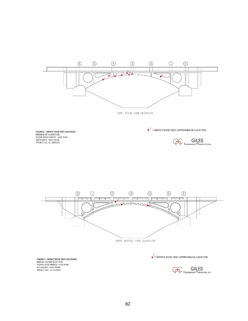
82

83

84

85

86

87

88

89

90

91

92

93

94

95

96

II. APPENDIX C – AESBESTOS REPORT
97

98

99

III. APPENDIX D – SURVEY DATA
Lake Park pedestrian Bridge over Ravine Road
SURVEY information
Benchmarks1 benchmark on south side of bridge1(A) benchmark on south side of bridge2 benchmark on the north side of bridge#11 pk on north side of bridge
Outside edge of deck elevations, outside of parapetSurvey date
CONCRETE ELEVATION
Outside WEST parapet
Inside West parapet
Inside East parapet
Outside EAST parapet
Outside WEST parapet
Outside EAST parapet
Outside WEST parapet
Outside EAST parapet
South end of abutment 660.06 660.57 660.55 660.08 659.73 660.06 660.06South corner of octagon 660.39 661.18 661.22 660.65 660.41 660.65 660.39 660.65Midpoint of octagon 660.66 661.36 661.49 660.87 660.72 660.87 660.69 660.86North corner of octagon 660.93 661.52 661.55 660.97 660.93 660.99 660.93 660.960/10 point South end of deck 660.90 661.54 661.53 660.93 660.90 660.93 660.89 660.911/10 point at the pilaster 660.98 660.96 661.03 661.04 660.98 661.04 660.97 661.022/10 point at the pilaster 661.05 661.05 661.08 661.08 661.06 661.07 661.04 661.063/10 point at the pilaster 661.16 661.18 661.10 661.21 661.18 661.20 661.14 661.184/10 point at the pilaster 661.29 661.32 661.37 661.38 661.30 661.35 661.27 661.355/10 mid-point 661.43 661.43 661.46 661.47 661.42 661.45 661.41 661.446/10 point at the pilaster 661.33 661.31 661.30 661.31 661.33 661.31 661.30 661.297/10 point at the pilaster 661.21 661.19 661.20 661.25 661.20 661.22 661.18 661.218/10 point at the pilaster 661.09 661.07 661.10 661.18 661.10 661.13 661.07 661.119/10 point at the pilaster 661.05 661.06 661.06 661.10 661.06 661.07 661.04 661.0610/10 point North end of deck 660.94 660.99 660.99 661.02 660.94 660.96 660.91 660.94South corner of octagon 660.91 661.55 661.54 660.98 660.94 660.95 660.93 660.94Midpoint of octagon 660.99 661.65 661.63 660.92 661.03 660.91 660.97 660.91North corner of octagon 660.90 661.51 661.49 660.81 660.90 660.81 660.89 660.80North end of the abutment 660.66 661.21 661.01 660.39 660.69 660.39 660.69 660.39
SW corner concrete wall @ grand staircase#10 pk ion southside of bridge
9-Mar-15 2-Apr-15 23-Apr-15
100

IV. APPENDIX E – ESTIMATED CONSTRUCTION COSTS
101

102

103

Prefabricated Pedestrian Truss Bridge ReplacementLake Park Drive Bridge over Ravine Road
Structure P-40-576
Estimated Estimated TotalQuantity Unit Cost Estimated Cost
Demolition LS 1 120,000$ 120,000$ Excavation for structure/Site Grading/Clearing & Grubbing LS 1 80,000$ 80,000$ New Prefabricated Pedestrian Bridge Structure LS 1 550,000$ 550,000$ Mobilization LS 1 120,000$ 120,000$ Traffic Control LS 1 25,000$ 25,000$ Staging & Site/slope Re-grading Restoration/Protection LS 2 50,000$ 100,000$ Concrete Staining/anti Graffitti SF 256 12$ 3,000$ Approach Trail & Entrance reconstruction LS 2 17,500$ 35,000$ Street Lighting LS 1 25,000$ 25,000$
1,058,000$ Total Estimated Design Services: 159,000$
15% Estimated Construction Contingencies/Allowance: 159,000$ 12% Construction Management: 127,000$
10% Owner Services: 106,000$ Total Project Cost Estimate: 1,609,000$
UnitItem
104

Prestressed Concrete Girder Bridge ReplacementLake Park Drive Bridge over Ravine Road
Structure P-40-576Estimated Estimated TotalQuantity Unit Cost Estimated Cost
Demolition LS 1 120,000$ 120,000$ Excavation for structure/Site Grading/Clearing & Grubbing LS 1 80,000$ 80,000$ New Prestressed Concrete Grider Bridge Structure LS 1 375,000$ 375,000$ Decorative Precast Panels SF 3800 32$ 122,000$ Mobilization LS 1 120,000$ 120,000$ Traffic Control LS 1 25,000$ 25,000$ Staging & Site/slope Re-grading Restoration/Protection LS 2 50,000$ 100,000$ Concrete Staining/anti Graffitti SF 874 12$ 10,000$ Approach Trail & Entrance reconstruction LS 2 17,500$ 35,000$ Street Lighting LS 1 25,000$ 25,000$
1,012,000$ Total Estimated Design Services: 152,000$
15% Estimated Construction Contingencies/Allowance: 152,000$ 12% Construction Management: 121,000$
10% Owner Services: 101,000$ Total Project Cost Estimate: 1,538,000$
Item Unit
105