high voltage stimulation - practical application and...
TRANSCRIPT
Original Article Citation: Neurophysiol. Lab. 27/2 (2005), p. 61-88 Elsevier – Urban & Fischer www.elsevier.de/neurophys Neurological Clinic, Aschaffenburg, Germany High Voltage Stimulation - Practical Application and Clinical Examples Klaus Gardill Summary
High voltage stimulation (HVS) allows supramaximal stimulation of proximal peripheral nerves down to the nerve roots and the plexus, thus making them accessible to neurographic investigation. In particular, useful information can be obtained in this manner with respect to demyelinating disorders of peripheral nerves. For that purpose, this article shows practical application of HVS and moreover presents instructive clinical examples concerning the most important indications.
Key words: High voltage stimulation, proximal nerve conduction studies, demyelinating neuropathies, Guillain-Barré syndrome (GBS), polyneuritis
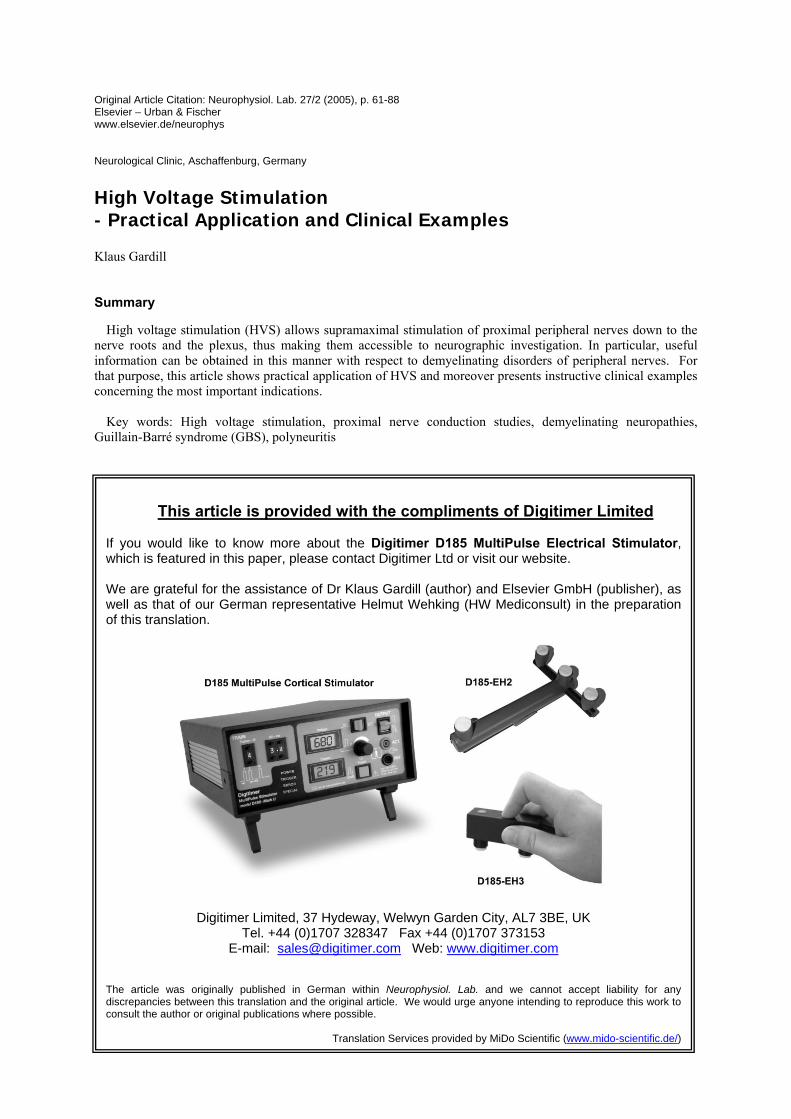
This article is provided with the compliments of Digitimer Limited
If you would like to know more about the Digitimer D185 MultiPulse Electrical Stimulator, which is featured in this paper, please contact Digitimer Ltd or visit our website. We are grateful for the assistance of Dr Klaus Gardill (author) and Elsevier GmbH (publisher), as well as that of our German representative Helmut Wehking (HW Mediconsult) in the preparation of this translation.
Digitimer Limited, 37 Hydeway, Welwyn Garden City, AL7 3BE, UK
Tel. +44 (0)1707 328347 Fax +44 (0)1707 373153 E-mail: [email protected] Web: www.digitimer.com
The article was originally published in German within Neurophysiol. Lab. and we cannot accept liability for any discrepancies between this translation and the original article. We would urge anyone intending to reproduce this work to consult the author or original publications where possible.
Translation Services provided by MiDo Scientific (www.mido-scientific.de/)
• K. Gardill
2
Introduction
Sites of damage to nerves in the distal extremities can be reliably identified with conventional electroneurography (ENG) and evidence can be obtained as to the nature and extent of the damage.
The study of proximal nerve regions including nerve roots and plexi is much more difficult. This is mainly due to the fact that deep nerve fibres are covered by large amounts of other tissue (especially muscle) rendering them poorly accessible for stimulation. For this reason, techniques which detect proximal damage with far distal stimulation have succeeded in practice: F-wave and H-reflex studies are well established (overview in [6]).
These techniques are indeed well established and easy to perform, but they have a number of disadvantages: H-reflexes can be lacking in healthy individuals and F-waves, for example, are not sensitive parameters in radicular lesions [2]. Both techniques also have the disadvantage that localisation of the damage site is not possible.
An additional technique for examining sensory afferences is the recording of fractionated somatosensory evoked potentials (SEP, overview see [20]). This technique is relatively complex and requires a high degree of expertise and, especially in the lower extremities, spinal SEP can often not be recorded satisfactorily.
With the aid of electromyography (EMG), the consequences of denervation or reinnervation following proximal nerve damage can be found in muscle with high sensitivity. However, in this case there must be damage to axons (damage to the myelin sheath cannot be detected), and the damage usually has to have existed at least 10 to14 days before denervation can be detected. In addition, the method is not painless and takes a relatively long time.
So-called Magnetic simulation is a reliable means of stimulating the brain or proximal nerves with recording of the resulting evoked motor activity in a manner similar to motor electroneurography (summary see [7]). The disadvantage of the method, however, is that reliable supramaximal stimulation of all nerves often fails to render a reliable conduction block diagnosis (e.g. as an expression of acute demyelinating damage). It is also often not possible to locate the precise stimulation site on the nerve, which leads to inaccuracies in the determination of latency or nerve conduction velocity (NCV).
High voltage stimulation (HVS), originally developed for cortex stimulation [15] has been increasingly used since the 1980s for the stimulation of proximal nerves. The devices normally available in conventional electroneurography allow constant current or constant voltage nerve stimulation with their stimulators. Usually, voltages up to approximately 300 V and currents up to around 100 mA are used with a stimulation period of around 0.1 to 0.5 ms. However, in high voltage stimulation voltages up to 1000 V and currents up to over 1000 mA are possible, which also provide low output impedance stimuli with a high rise rate and exponential decay†. In most cases it is also possible to reliably stimulate proximal nerves supramaximally with these stimuli.
These stimulators can be found in many clinical neurophysiology laboratories, nevertheless the technique is not (yet) part of the standard programme in most neurophysiology clinics or practices. There are certainly many reasons for this: High voltage stimulation receives little attention, both in scientific literature and in the established neurophysiology textbooks. Standard values are hardly ever published, and there are some significant methodical differences in published studies. In addition, patients always associate the term high voltage stimulation with considerable unpleasantness.
This article provides a practical overview of the application options of HVS in the neurophysiology laboratory.
† Manufacturers Note: The Digitimer D185 actually produces a rectangular pulse shape with extremely rapid rise and fall times, and a pulse duration of 50µs. This results in a very brief stimulus which effectively reduces patient discomfort.
High Voltage Stimulation – Practical Application and Clinical Examples •
3
Pathophysiology
Highly simplified, damage to peripheral nerves can be divided into axonal (i.e. affecting the nerve fibre (“cable”) itself) and demyelinating (i.e. affecting the sheath of the nerve fibre (the “insulation”)) damage. The electrophysiological techniques described above yield results, which indicate one or other (or both) of the types of damage. This provides very valuable information on the pathomechanism underlying the nerve damage and hence ultimately to the causal disorder.
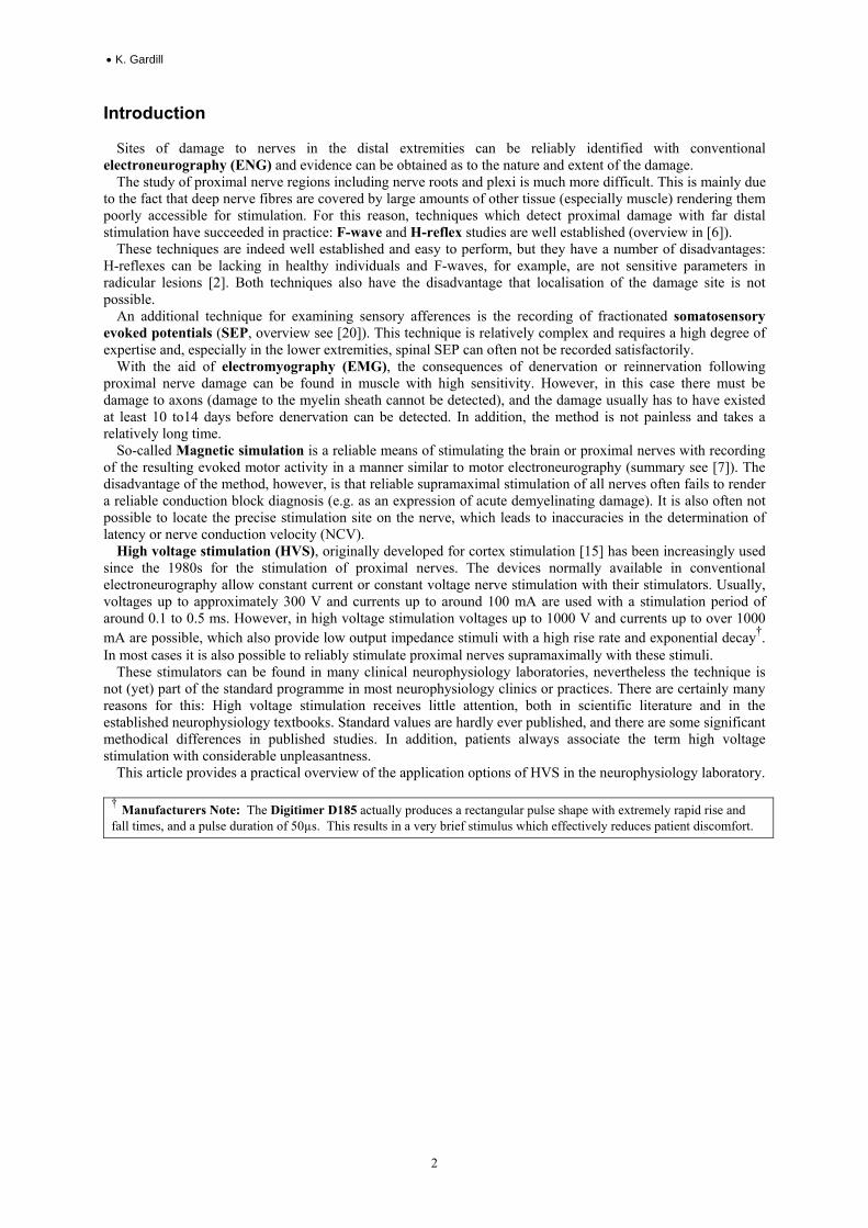
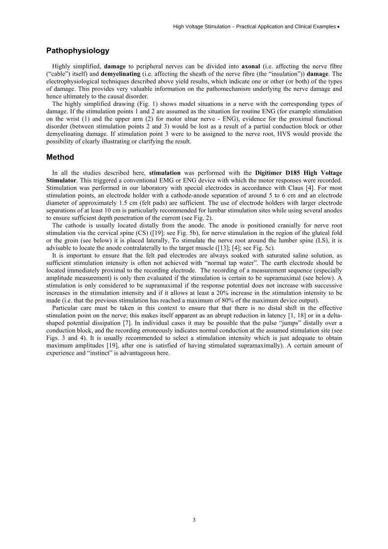
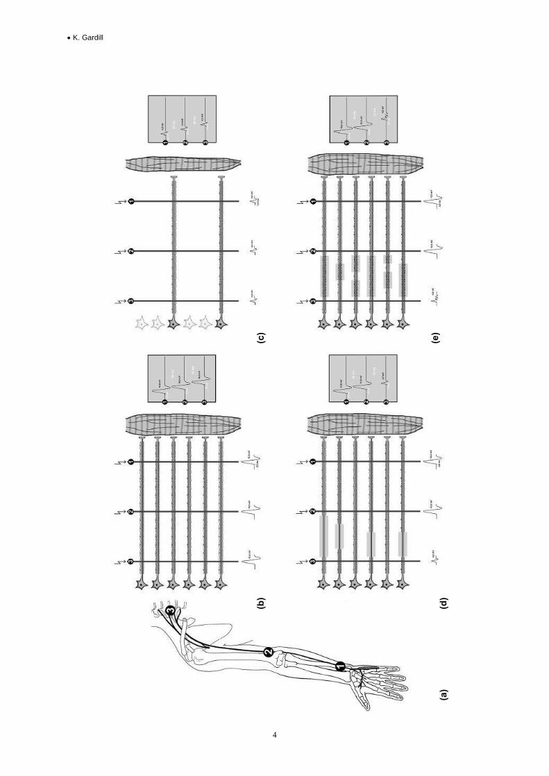
The highly simplified drawing (Fig. 1) shows model situations in a nerve with the corresponding types of damage. If the stimulation points 1 and 2 are assumed as the situation for routine ENG (for example stimulation on the wrist (1) and the upper arm (2) for motor ulnar nerve - ENG), evidence for the proximal functional disorder (between stimulation points 2 and 3) would be lost as a result of a partial conduction block or other demyelinating damage. If stimulation point 3 were to be assigned to the nerve root, HVS would provide the possibility of clearly illustrating or clarifying the result. Method
In all the studies described here, stimulation was performed with the Digitimer D185 High Voltage Stimulator. This triggered a conventional EMG or ENG device with which the motor responses were recorded. Stimulation was performed in our laboratory with special electrodes in accordance with Claus [4]. For most stimulation points, an electrode holder with a cathode-anode separation of around 5 to 6 cm and an electrode diameter of approximately 1.5 cm (felt pads) are sufficient. The use of electrode holders with larger electrode separations of at least 10 cm is particularly recommended for lumbar stimulation sites while using several anodes to ensure sufficient depth penetration of the current (see Fig. 2).
The cathode is usually located distally from the anode. The anode is positioned cranially for nerve root stimulation via the cervical spine (CS) ([19]; see Fig. 5b), for nerve stimulation in the region of the gluteal fold or the groin (see below) it is placed laterally, To stimulate the nerve root around the lumber spine (LS), it is advisable to locate the anode contralaterally to the target muscle ([13]; [4]; see Fig. 5c).
It is important to ensure that the felt pad electrodes are always soaked with saturated saline solution, as sufficient stimulation intensity is often not achieved with “normal tap water”. The earth electrode should be located immediately proximal to the recording electrode. The recording of a measurement sequence (especially amplitude measurement) is only then evaluated if the stimulation is certain to be supramaximal (see below). A stimulation is only considered to be supramaximal if the response potential does not increase with successive increases in the stimulation intensity and if it allows at least a 20% increase in the stimulation intensity to be made (i.e. that the previous stimulation has reached a maximum of 80% of the maximum device output).
Particular care must be taken in this context to ensure that that there is no distal shift in the effective stimulation point on the nerve; this makes itself apparent as an abrupt reduction in latency [1, 18] or in a delta-shaped potential dissipation [7]. In individual cases it may be possible that the pulse “jumps” distally over a conduction block, and the recording erroneously indicates normal conduction at the assumed stimulation site (see Figs. 3 and 4). It is usually recommended to select a stimulation intensity which is just adequate to obtain maximum amplitudes [19], after one is satisfied of having stimulated supramaximally). A certain amount of experience and “instinct” is advantageous here.
• K. Gardill
4
(a)
(b)
(d)
(c)
(e)
High Voltage Stimulation – Practical Application and Clinical Examples •
5
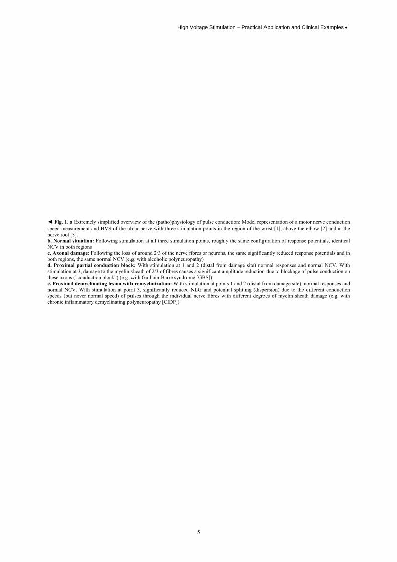
◄ Fig. 1. a Extremely simplified overview of the (patho)physiology of pulse conduction: Model representation of a motor nerve conduction speed measurement and HVS of the ulnar nerve with three stimulation points in the region of the wrist [1], above the elbow [2] and at the nerve root [3]. b. Normal situation: Following stimulation at all three stimulation points, roughly the same configuration of response potentials, identical NCV in both regions c. Axonal damage: Following the loss of around 2/3 of the nerve fibres or neurons, the same significantly reduced response potentials and in both regions, the same normal NCV (e.g. with alcoholic polyneuropathy) d. Proximal partial conduction block: With stimulation at 1 and 2 (distal from damage site) normal responses and normal NCV. With stimulation at 3, damage to the myelin sheath of 2/3 of fibres causes a significant amplitude reduction due to blockage of pulse conduction on these axons (”conduction block”) (e.g. with Guillain-Barré syndrome [GBS]) e. Proximal demyelinating lesion with remyelinization: With stimulation at points 1 and 2 (distal from damage site), normal responses and normal NCV. With stimulation at point 3, significantly reduced NLG and potential splitting (dispersion) due to the different conduction speeds (but never normal speed) of pulses through the individual nerve fibres with different degrees of myelin sheath damage (e.g. with chronic inflammatory demyelinating polyneuropathy [CIDP])
• K. Gardill
6
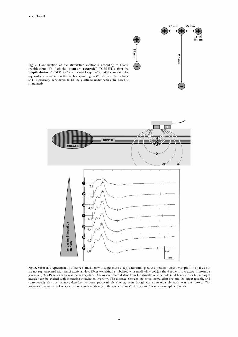
Fig 2. Configuration of the stimulation electrodes according to Claus’ specifications [4]: Left the “standard electrode” (D185-EH3), right the “depth electrode” (D185-EH2) with special depth effect of the current pulse especially to stimulate in the lumbar spine region (“-” denotes the cathode and is generally considered to be the electrode under which the nerve is stimulated).
Fig. 3. Schematic representation of nerve stimulation with target muscle (top) and resulting curves (bottom, subject example): The pulses 1-3 are not supramaximal and cannot excite all deep fibres (excitation symbolised with small white dots). Pulse 4 is the first to excite all axons, a potential (CMAP) arises with maximum amplitude. Axons ever more distant from the stimulation electrode (and hence closer to the target muscle) can be excited with increasing stimulation intensity. The distance between the actual stimulation site and the target muscle, and consequently also the latency, therefore becomes progressively shorter, even though the stimulation electrode was not moved. The progressive decrease in latency arises relatively erratically in the real situation (“latency jump”, also see example in Fig. 4).
High Voltage Stimulation – Practical Application and Clinical Examples •
7
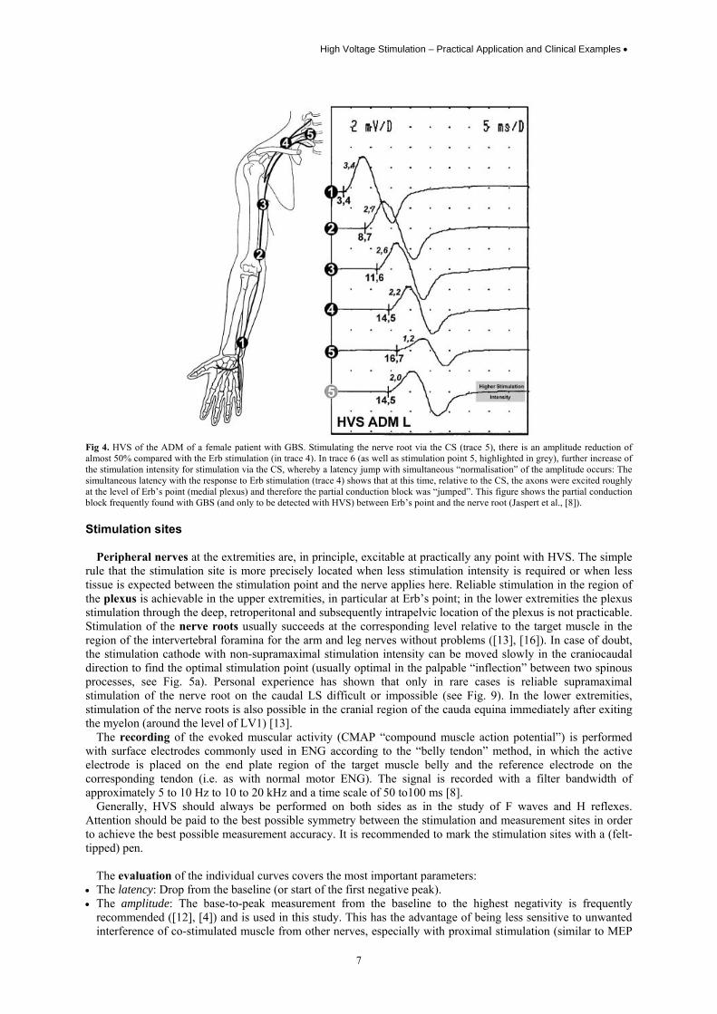
Fig 4. HVS of the ADM of a female patient with GBS. Stimulating the nerve root via the CS (trace 5), there is an amplitude reduction of almost 50% compared with the Erb stimulation (in trace 4). In trace 6 (as well as stimulation point 5, highlighted in grey), further increase of the stimulation intensity for stimulation via the CS, whereby a latency jump with simultaneous “normalisation” of the amplitude occurs: The simultaneous latency with the response to Erb stimulation (trace 4) shows that at this time, relative to the CS, the axons were excited roughly at the level of Erb’s point (medial plexus) and therefore the partial conduction block was “jumped”. This figure shows the partial conduction block frequently found with GBS (and only to be detected with HVS) between Erb’s point and the nerve root (Jaspert et al., [8]). Stimulation sites
Peripheral nerves at the extremities are, in principle, excitable at practically any point with HVS. The simple rule that the stimulation site is more precisely located when less stimulation intensity is required or when less tissue is expected between the stimulation point and the nerve applies here. Reliable stimulation in the region of the plexus is achievable in the upper extremities, in particular at Erb’s point; in the lower extremities the plexus stimulation through the deep, retroperitonal and subsequently intrapelvic location of the plexus is not practicable. Stimulation of the nerve roots usually succeeds at the corresponding level relative to the target muscle in the region of the intervertebral foramina for the arm and leg nerves without problems ([13], [16]). In case of doubt, the stimulation cathode with non-supramaximal stimulation intensity can be moved slowly in the craniocaudal direction to find the optimal stimulation point (usually optimal in the palpable “inflection” between two spinous processes, see Fig. 5a). Personal experience has shown that only in rare cases is reliable supramaximal stimulation of the nerve root on the caudal LS difficult or impossible (see Fig. 9). In the lower extremities, stimulation of the nerve roots is also possible in the cranial region of the cauda equina immediately after exiting the myelon (around the level of LV1) [13].
The recording of the evoked muscular activity (CMAP “compound muscle action potential”) is performed with surface electrodes commonly used in ENG according to the “belly tendon” method, in which the active electrode is placed on the end plate region of the target muscle belly and the reference electrode on the corresponding tendon (i.e. as with normal motor ENG). The signal is recorded with a filter bandwidth of approximately 5 to 10 Hz to 10 to 20 kHz and a time scale of 50 to100 ms [8].
Generally, HVS should always be performed on both sides as in the study of F waves and H reflexes. Attention should be paid to the best possible symmetry between the stimulation and measurement sites in order to achieve the best possible measurement accuracy. It is recommended to mark the stimulation sites with a (felt-tipped) pen.
The evaluation of the individual curves covers the most important parameters:
• The latency: Drop from the baseline (or start of the first negative peak). • The amplitude: The base-to-peak measurement from the baseline to the highest negativity is frequently
recommended ([12], [4]) and is used in this study. This has the advantage of being less sensitive to unwanted interference of co-stimulated muscle from other nerves, especially with proximal stimulation (similar to MEP
• K. Gardill
8
([7], [4]). However, the use of peak-to-peak measurement is also recommended ([18], [10]). Personal experience has shown both methods to be practicable.
• The potential duration as well as the area (especially of the first negative peak) should also be considered. The former is particularly important for delimiting the conduction block from amplitude reduction due to potential dispersion.
• The nerve conduction speeds (NCSs) can also be determined in the extremities by conventional motor ENG. As we usually performed HVS subsequent to conventional recording, this parameter was often not determined again in the recordings illustrated here. Determination of NCS proximally in the region of the plexus and nerve roots is not possible, as both the stimulation site (as a result of the incalculable depth effect of the stimulation current) as well as the conduction path between two stimulation sites cannot be determined with any more accuracy proximally.
To evaluate amplitude reductions arising from a partial conduction block, reference is made to the relevant
criteria from the specialist associations (e.g. American Association of Electrodiagnostic Medicine (AAEM, [17]).
Collision technique
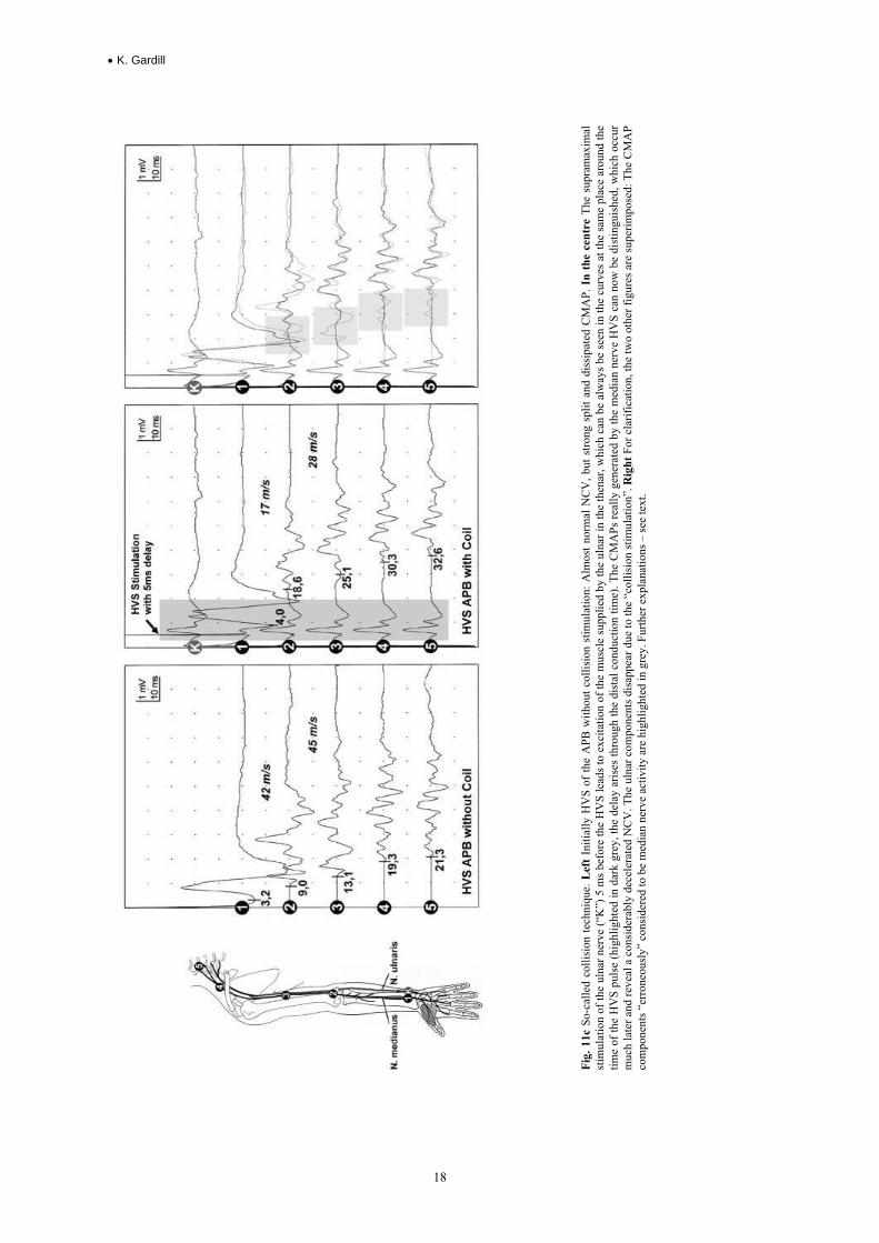
Interference of “involuntarily” co-activated muscles can cause problems, especially in the case of proximal stimulation in the region of the nerve root or plexus. This particularly occurs if the target muscle is surrounded by muscle innervated by other nerves (e.g. when stimulating the median nerve and recording from the abductor pollicis brevis muscle, the interference from the thenar muscles supplied by the ulnar nerve) and the supplying nerves are close together at the stimulation points. Help is provided here by Kimura’s so-called collision technique [11]. Here the unwanted activity is eliminated by stimulating the affected (“unwanted”) nerve a few milliseconds before the separate high voltage stimulation. The pulse is then conducted both orthodromically to the target muscle as well as antidromically centrally and collides with the pulse arriving orthodromically, which was triggered by the high voltage stimulation. The high voltage pulse is not conducted distally to the muscle and therefore no interference occurs [14]. The time interval between the two stimuli should be selected such that the antidromic pulse from the distal stimulation (the “collision pulse”) has not yet reached the stimulation point proximal to the stimulation point there (from the HVS pulse) at the time of stimulation. On the other hand, the time interval should be sufficiently long to map the response to the HVS onto a stable baseline (without interference from the “collision pulse” potential). Fig. 11c shows an example.
Study options
In principle, all “important” nerves at the extremities can be studied with HVS. The ulnar nerve and the abductor digiti minimi muscle are particularly well suited due to the low potential for interference from the muscle activity of other nerves at the recording electrode [1]. A series of other suitable muscles is given in Table 1.
Instructions on localising the stimulation points
Arm nerves: The spinous process of the 7th cervical vertebra usually protrudes most of all (“vertebra prominens”, see Fig. 5a). For the median, ulnar and radial nerves, the cathode may be placed in the interstitial space above (i.e. between the 6th and 7th cervical vertebra, corr. to C7) or below (i.e. between the 7th cervical vertebra and the 1st thoracic vertebra), whereby, if in doubt both sites can be tried. For the other arm nerves, one can move one or two interstitial spaces towards the cranial.
Leg nerves: The excitation point L5 is found in the middle of a line between the two pelvic chambers caudally across the spine in the next interstitial space between two spinous processes. For the stimulation point L1: Feel the edge of the costal arch at the crossing point of a connection line of both costal arches with the spine roughly a handbreadth towards the cranial: L1 is located there.
Indications
The domain of HVS principally covers demyelinating diseases concentrated in proximal nerve regions, as it is often not possible to map these with conventional electroneurographic techniques and EMG often fails to yield any relevant additional information (Table 2).
In this context, it is worthy of note that the precise localisation of conduction blocks or temporary dispersion as an expression of focal demyelinization can provide important information, e.g. to differentiate between an inflammatory (CIDP) and a hereditary PNP (HNPP – hereditary neuropathy with liability to pressure palsies) [5]. For this reason, an “inching” technique should be used if possible to detect the damage site outside of predilection points ([3]; technique - see example in Fig. 19).
High Voltage Stimulation – Practical Application and Clinical Examples •
9
Standard values In general it is recommended to observe the length of the extremities studied. Unfortunately, there are no
standard techniques in the literature. A simple alternative involves using body size, which can be determined conclusively and quickly. However, there are hardly any standard values published in this regard. Latencies
As a pragmatic approach, we use the latency values, which are not related to body size or extremity lengths, from Table 3 in our laboratory.
Amplitudes
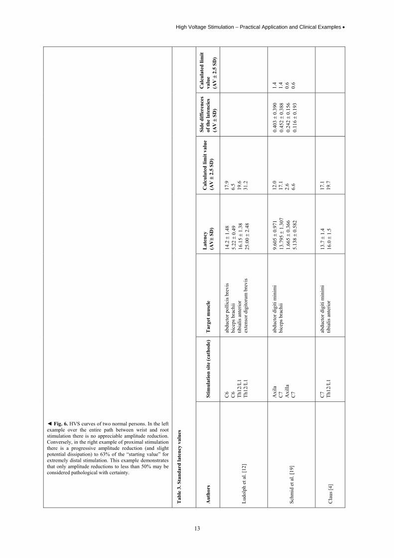
The standard values from conventional electroneurography apply to the distal extremities, as the results may be viewed as identical with those from HVS [10]. For the proximal arm nerve stimulation points: In recording from the ADM and comparison between wrist and cervical spine, Jaspert et al. [8] consider an amplitude difference of more than 50% as pathological (also see Fig. 6). From personal experience, this value can certainly also serve as a reference point when investigating other nerve / target muscle of the upper extremities. For the leg nerves, Claus [4] specifies a limit value of amplitude Th12/L1 to fibula head for the tibialis anterior muscle of 32%. According to personal, practical experience, this value is selected rather cautiously, as we have never seen a drop to below 50% in our own laboratory with healthy subjects (with certain supramaximal stimulation).
In addition, in the investigation of individual nerve segments the generally applicable recommendations for the diagnosis of a conduction block with conventional motor electroneurography (see above) also apply to HVS (see above).
As an extraordinary inter-individual variability in latencies and also amplitudes exists for the normal case, the increase in sensitivity of the method should always be accompanied by a comparison with healthy persons.
• K. Gardill
10
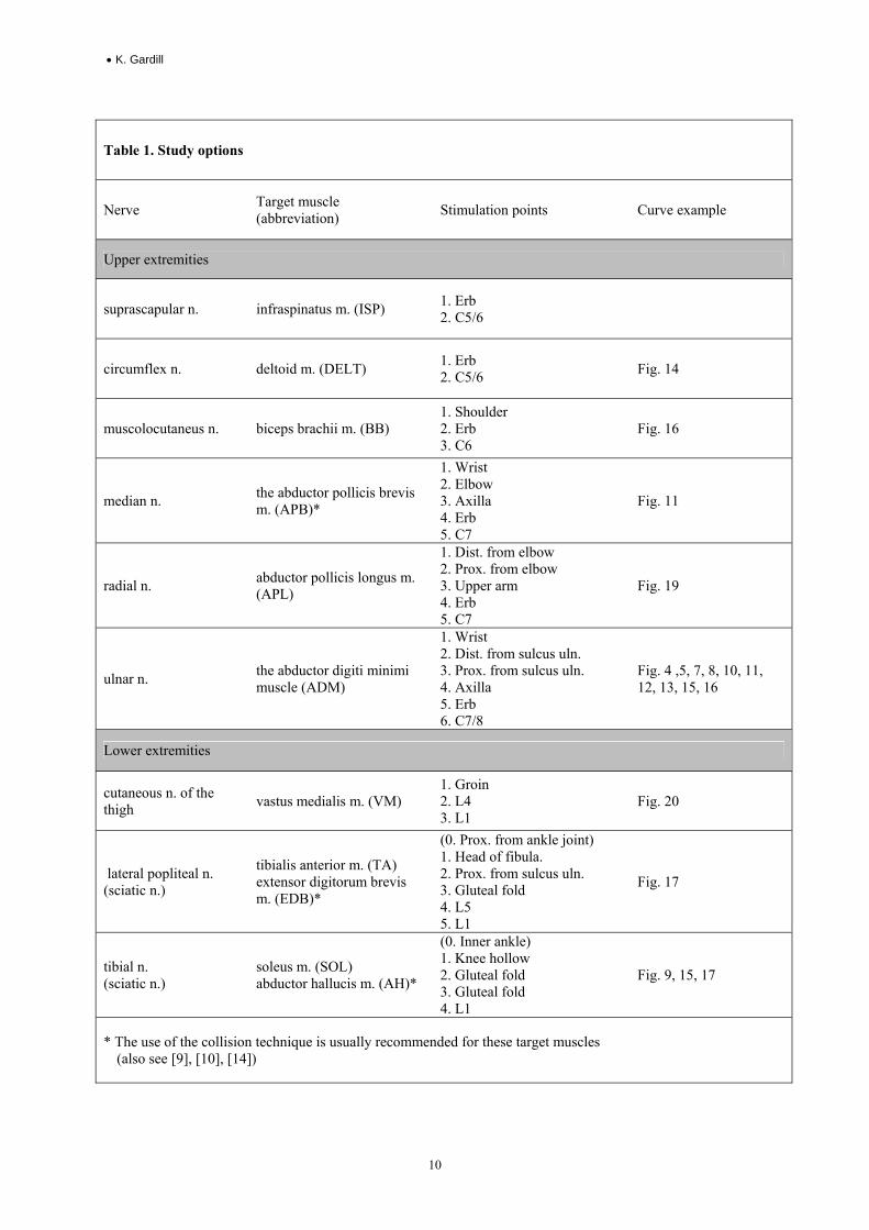
Table 1. Study options
Nerve Target muscle (abbreviation) Stimulation points Curve example
Upper extremities
suprascapular n. infraspinatus m. (ISP) 1. Erb 2. C5/6
circumflex n. deltoid m. (DELT) 1. Erb 2. C5/6 Fig. 14
muscolocutaneus n. biceps brachii m. (BB) 1. Shoulder 2. Erb 3. C6
Fig. 16
median n. the abductor pollicis brevis m. (APB)*
1. Wrist 2. Elbow 3. Axilla 4. Erb 5. C7
Fig. 11
radial n. abductor pollicis longus m. (APL)
1. Dist. from elbow 2. Prox. from elbow 3. Upper arm 4. Erb 5. C7
Fig. 19
ulnar n. the abductor digiti minimi muscle (ADM)
1. Wrist 2. Dist. from sulcus uln. 3. Prox. from sulcus uln. 4. Axilla 5. Erb 6. C7/8
Fig. 4 ,5, 7, 8, 10, 11, 12, 13, 15, 16
Lower extremities
cutaneous n. of the thigh vastus medialis m. (VM)
1. Groin 2. L4 3. L1
Fig. 20
lateral popliteal n. (sciatic n.)
tibialis anterior m. (TA) extensor digitorum brevis m. (EDB)*
(0. Prox. from ankle joint) 1. Head of fibula. 2. Prox. from sulcus uln. 3. Gluteal fold 4. L5 5. L1
Fig. 17
tibial n. (sciatic n.)
soleus m. (SOL) abductor hallucis m. (AH)*
(0. Inner ankle) 1. Knee hollow 2. Gluteal fold 3. Gluteal fold 4. L1
Fig. 9, 15, 17
* The use of the collision technique is usually recommended for these target muscles (also see [9], [10], [14])
High Voltage Stimulation – Practical Application and Clinical Examples •
11
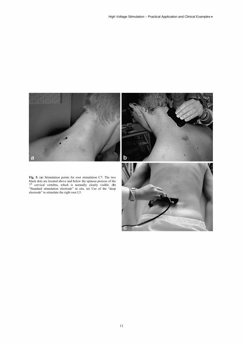
Fig. 5. (a) Stimulation points for root stimulation C7: The two black dots are located above and below the spinous process of the 7th cervical vertebra, which is normally clearly visible. (b) “Standard stimulation electrode” in situ. (c) Use of the “deep electrode” to stimulate the right root L5.

• K. Gardill
12
Table 2. Indications
Indication Curve example
1. Inflammatory (poly)neuropathies • Guillain-Barré syndrome (GBS; also acute inflammatory demyelinating
polyneuropathy, AIDP) • Chronic inflammatory demyelinating polyneuropathy (CIPD) • Multifocal motor neuropathy (MMN) • Neuralgic amyotrophy
Fig. 4, 7, 8, 9 Fig. 10,11 Fig. 12, 13 Fig. 14
2. Non-inflammatory polyneuropathies
• Hereditary polyneuropathies • Other polyneuropathies to exclude DD
Fig. 15
3. Lesions of proximal nerves or lesions of the arm or leg innervation plexus
• Traumatic lesions • Pressure damage / tunnel syndrome • Other lesions
Fig. 16 Fig. 17
4. Lesions of the nerve roots or cauda equina
• Lesions relating to lumber disc (but often limited by pain) • Tumours and other spatial constraints • Traumatic lesions
Fig. 18
5. Lesions of peripheral nerve segments, poorly accessible with conventional stimulation
• Particularly precise localisation of conduction blocks through the investigation of
short segments
Fig. 19
High Voltage Stimulation – Practical Application and Clinical Examples •
13
Cal
cula
ted
limit
valu
e (A
V ±
2.5
SD
)
1.4
1.4
0.6
0.6
Side
diff
eren
ces
of th
e la
tenc
ies
(AV
± S
D)
0.40
3 ±
0.39
0 0.
452 ±
0.38
8 0.
242 ±
0.15
6 0.
116 ±
0.19
3
Cal
cula
ted
limit
valu
e (A
V ±
2.5
SD
)
17.9
6.
5 19
.6
31.2
12.0
17
.1
2.6
6.6
17.1
19
.7
Lat
ency
(A
V±
SD)
14.2
± 1
.48
5.22
± 0
.49
16.1
5 ±
1.38
25
.00 ±
2.48
9.60
5 ±
0.97
1 13
.795
± 1
.307
1.
665 ±
0.36
6 5.
138 ±
0.58
2
13.7
± 1
.4
16.0
± 1
.5
Tar
get m
uscl
e
abdu
ctor
pol
licis
bre
vis
bice
ps b
rach
ii tib
ialis
ant
erio
r ex
tens
or d
igito
rum
bre
vis
abdu
ctor
dig
iti m
inim
i bi
ceps
bra
chii
abdu
ctor
dig
iti m
inim
i tib
ialis
ant
erio
r
Stim
ulat
ion
site
(cat
hode
)
C6
C6
Th12
/L1
Th12
/L1
Axi
la
C7
Axi
lla
C7
C7
Th12
/L1
◄ Fig. 6. HVS curves of two normal persons. In the left example over the entire path between wrist and root stimulation there is no appreciable amplitude reduction. Conversely, in the right example of proximal stimulation there is a progressive amplitude reduction (and slight potential dissipation) to 63% of the “starting value” for extremely distal stimulation. This example demonstrates that only amplitude reductions to less than 50% may be considered pathological with certainty.
Tab
le 3
. Sta
ndar
d la
tenc
y va
lues
Aut
hors
Ludo
lph
et a
l. [1
2]
Schm
id e
t al.
[19]
Cla
us [4
]
• K. Gardill
14
Clinical examples
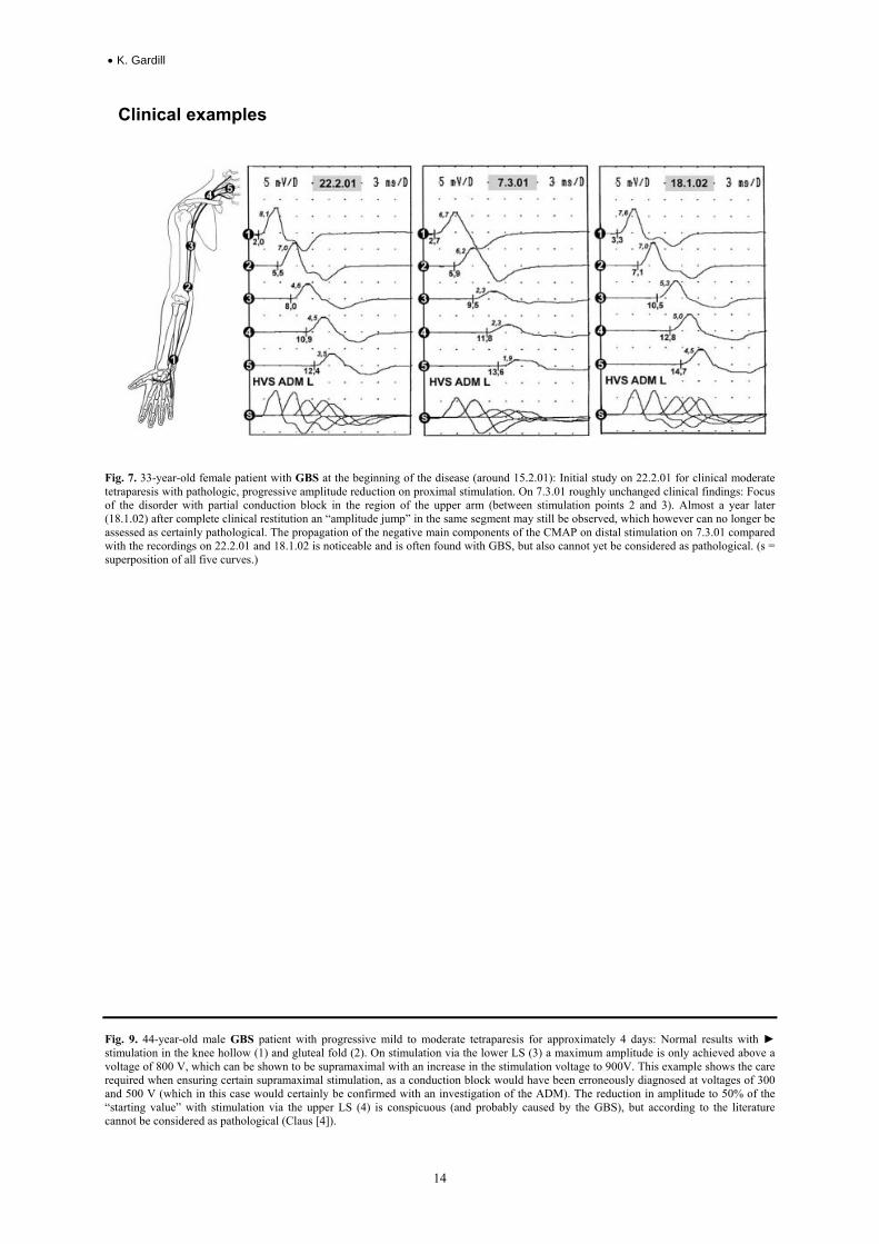
Fig. 7. 33-year-old female patient with GBS at the beginning of the disease (around 15.2.01): Initial study on 22.2.01 for clinical moderate tetraparesis with pathologic, progressive amplitude reduction on proximal stimulation. On 7.3.01 roughly unchanged clinical findings: Focus of the disorder with partial conduction block in the region of the upper arm (between stimulation points 2 and 3). Almost a year later (18.1.02) after complete clinical restitution an “amplitude jump” in the same segment may still be observed, which however can no longer be assessed as certainly pathological. The propagation of the negative main components of the CMAP on distal stimulation on 7.3.01 compared with the recordings on 22.2.01 and 18.1.02 is noticeable and is often found with GBS, but also cannot yet be considered as pathological. (s = superposition of all five curves.)
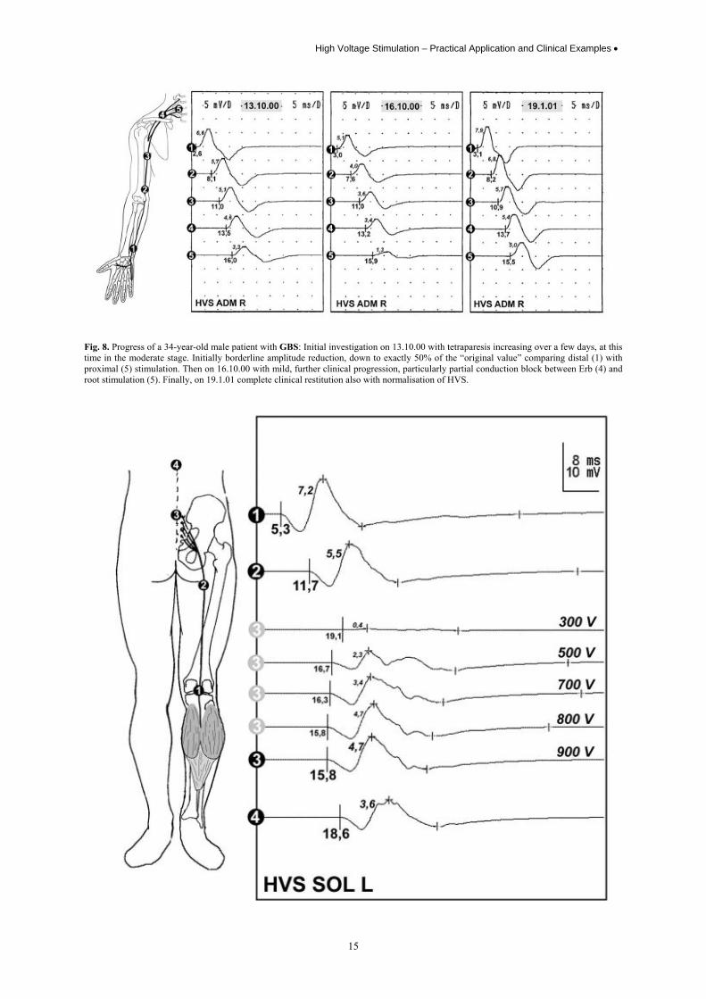
Fig. 9. 44-year-old male GBS patient with progressive mild to moderate tetraparesis for approximately 4 days: Normal results with ► stimulation in the knee hollow (1) and gluteal fold (2). On stimulation via the lower LS (3) a maximum amplitude is only achieved above a voltage of 800 V, which can be shown to be supramaximal with an increase in the stimulation voltage to 900V. This example shows the care required when ensuring certain supramaximal stimulation, as a conduction block would have been erroneously diagnosed at voltages of 300 and 500 V (which in this case would certainly be confirmed with an investigation of the ADM). The reduction in amplitude to 50% of the “starting value” with stimulation via the upper LS (4) is conspicuous (and probably caused by the GBS), but according to the literature cannot be considered as pathological (Claus [4]).
High Voltage Stimulation – Practical Application and Clinical Examples •
15
Fig. 8. Progress of a 34-year-old male patient with GBS: Initial investigation on 13.10.00 with tetraparesis increasing over a few days, at this time in the moderate stage. Initially borderline amplitude reduction, down to exactly 50% of the “original value” comparing distal (1) with proximal (5) stimulation. Then on 16.10.00 with mild, further clinical progression, particularly partial conduction block between Erb (4) and root stimulation (5). Finally, on 19.1.01 complete clinical restitution also with normalisation of HVS.
• K. Gardill
16
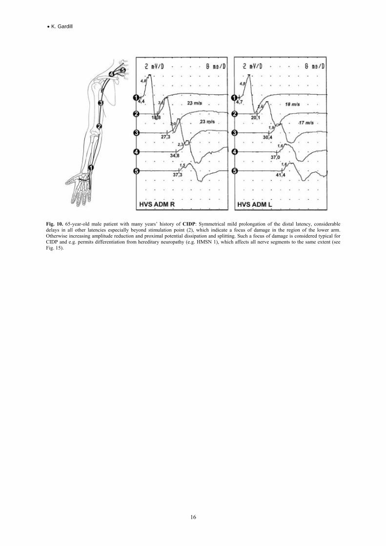
Fig. 10. 65-year-old male patient with many years’ history of CIDP: Symmetrical mild prolongation of the distal latency, considerable delays in all other latencies especially beyond stimulation point (2), which indicate a focus of damage in the region of the lower arm. Otherwise increasing amplitude reduction and proximal potential dissipation and splitting. Such a focus of damage is considered typical for CIDP and e.g. permits differentiation from hereditary neuropathy (e.g. HMSN 1), which affects all nerve segments to the same extent (see Fig. 15).
High Voltage Stimulation – Practical Application and Clinical Examples •
17
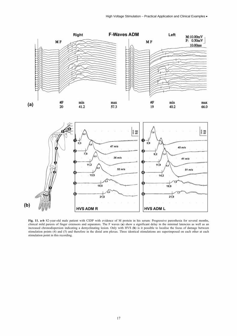
Fig. 11. a-b 82-year-old male patient with CIDP with evidence of M protein in his serum: Progressive paresthesia for several months, clinical mild paresis of finger extensors and separators. The F waves (a) show a significant delay in the minimal latencies as well as an increased chronodispersion indicating a demyelinating lesion. Only with HVS (b) is it possible to localise the focus of damage between stimulation points (4) and (5) and therefore in the distal arm plexus. Three identical stimulations are superimposed on each other at each stimulation point in this recording.
(a)
(b)
• K. Gardill
18
Fig.
11c
So-
calle
d co
llisi
on te
chni
que.
Lef
t In
itial
ly H
VS
of th
e A
PB w
ithou
t col
lisio
n st
imul
atio
n: A
lmos
t nor
mal
NC
V, b
ut s
trong
spl
it an
d di
ssip
ated
CM
AP.
In
the
cent
re T
he s
upra
max
imal
st
imul
atio
n of
the
ulna
r ner
ve (“
K”)
5 m
s be
fore
the
HV
S le
ads
to e
xcita
tion
of th
e m
uscl
e su
pplie
d by
the
ulna
r in
the
then
ar, w
hich
can
be
alw
ays
be s
een
in th
e cu
rves
at t
he s
ame
plac
e ar
ound
the
time
of th
e H
VS
puls
e (h
ighl
ight
ed in
dar
k gr
ey, t
he d
elay
aris
es th
roug
h th
e di
stal
con
duct
ion
time)
. The
CM
APs
real
ly g
ener
ated
by
the
med
ian
nerv
e H
VS
can
now
be
dist
ingu
ishe
d, w
hich
occ
ur
muc
h la
ter a
nd re
veal
a c
onsi
dera
bly
dece
lera
ted
NC
V. T
he u
lnar
com
pone
nts d
isap
pear
due
to th
e “c
ollis
ion
stim
ulat
ion”
. Rig
ht F
or c
larif
icat
ion,
the
two
othe
r fig
ures
are
supe
rimpo
sed:
The
CM
AP
com
pone
nts “
erro
neou
sly”
con
side
red
to b
e m
edia
n ne
rve
activ
ity a
re h
ighl
ight
ed in
gre
y. F
urth
er e
xpla
natio
ns –
see
text
.
High Voltage Stimulation – Practical Application and Clinical Examples •
19
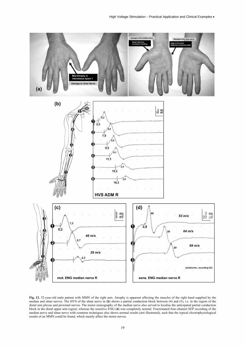
Fig. 12. 52-year-old male patient with MMN of the right arm. Atrophy is apparent affecting the muscles of the right hand supplied by the median and ulnar nerves. The HVS of the ulnar nerve in (b) shows a partial conduction block between (4) and (5), i.e. in the region of the distal arm plexus and proximal nerves. The motor neurography of the median nerve also served to localise the anticipated partial conduction block in the distal upper arm region; whereas the sensitive ENG (d) was completely normal. Fractionated four-channel SEP recording of the median nerve and ulnar nerve with common techniques also shows normal results (not illustrated), such that the typical electrophysiological results of an MMN could be found, which mainly affect the motor nerves.
(a)
(b)
(c) (d)
• K. Gardill
20
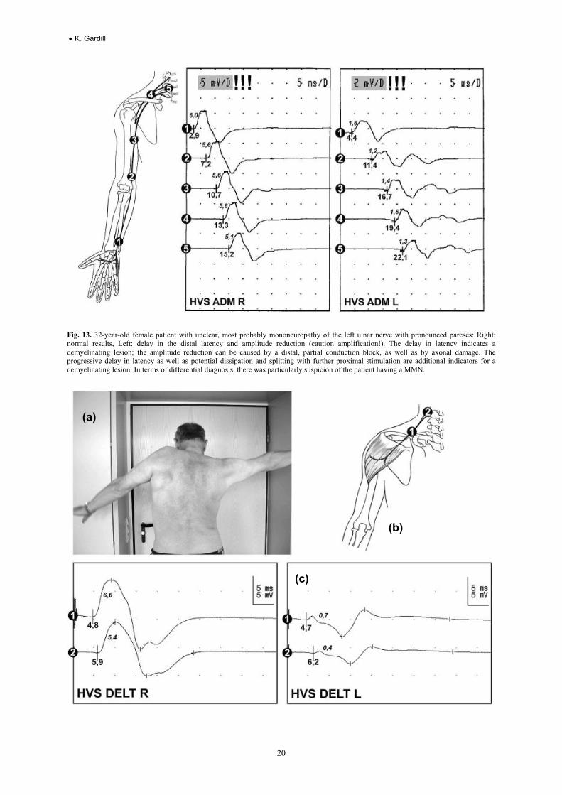
Fig. 13. 32-year-old female patient with unclear, most probably mononeuropathy of the left ulnar nerve with pronounced pareses: Right: normal results, Left: delay in the distal latency and amplitude reduction (caution amplification!). The delay in latency indicates a demyelinating lesion; the amplitude reduction can be caused by a distal, partial conduction block, as well as by axonal damage. The progressive delay in latency as well as potential dissipation and splitting with further proximal stimulation are additional indicators for a demyelinating lesion. In terms of differential diagnosis, there was particularly suspicion of the patient having a MMN.
(a)
(b)
(c)
High Voltage Stimulation – Practical Application and Clinical Examples •
21
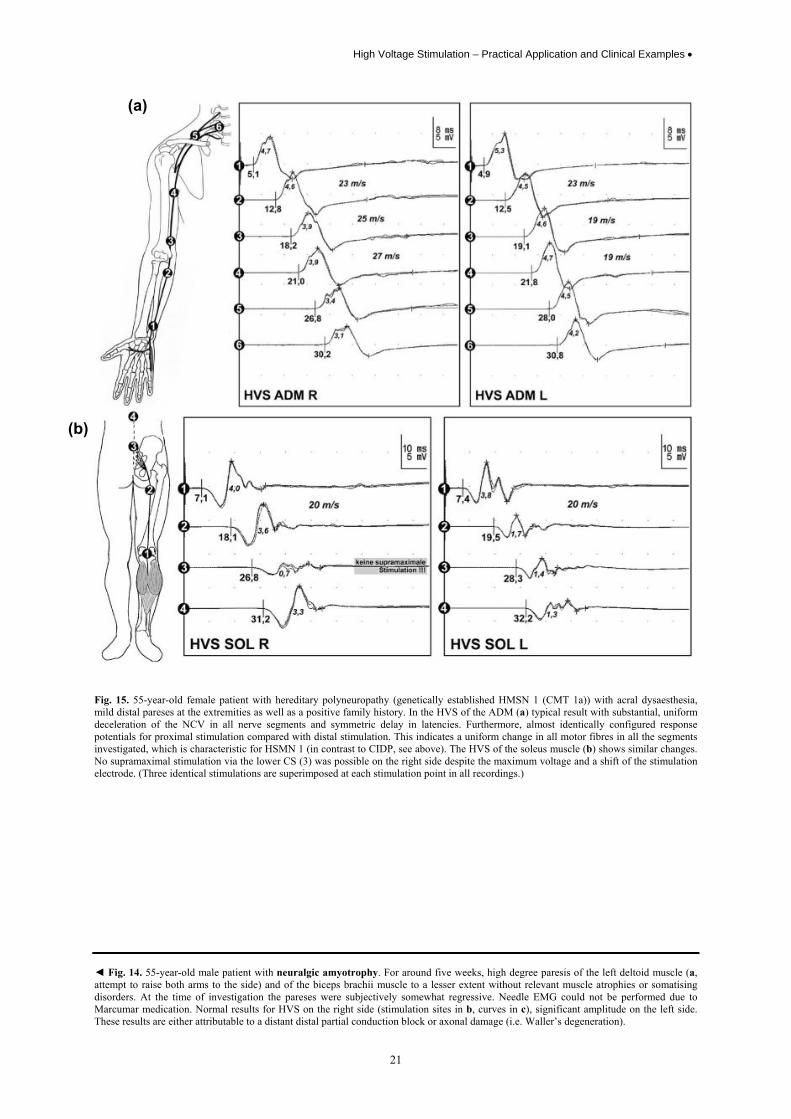
Fig. 15. 55-year-old female patient with hereditary polyneuropathy (genetically established HMSN 1 (CMT 1a)) with acral dysaesthesia, mild distal pareses at the extremities as well as a positive family history. In the HVS of the ADM (a) typical result with substantial, uniform deceleration of the NCV in all nerve segments and symmetric delay in latencies. Furthermore, almost identically configured response potentials for proximal stimulation compared with distal stimulation. This indicates a uniform change in all motor fibres in all the segments investigated, which is characteristic for HSMN 1 (in contrast to CIDP, see above). The HVS of the soleus muscle (b) shows similar changes. No supramaximal stimulation via the lower CS (3) was possible on the right side despite the maximum voltage and a shift of the stimulation electrode. (Three identical stimulations are superimposed at each stimulation point in all recordings.) ◄ Fig. 14. 55-year-old male patient with neuralgic amyotrophy. For around five weeks, high degree paresis of the left deltoid muscle (a, attempt to raise both arms to the side) and of the biceps brachii muscle to a lesser extent without relevant muscle atrophies or somatising disorders. At the time of investigation the pareses were subjectively somewhat regressive. Needle EMG could not be performed due to Marcumar medication. Normal results for HVS on the right side (stimulation sites in b, curves in c), significant amplitude on the left side. These results are either attributable to a distant distal partial conduction block or axonal damage (i.e. Waller’s degeneration).
(a)
(b)
• K. Gardill
22
(a)
(b)
(c)
(d)
High Voltage Stimulation – Practical Application and Clinical Examples •
23
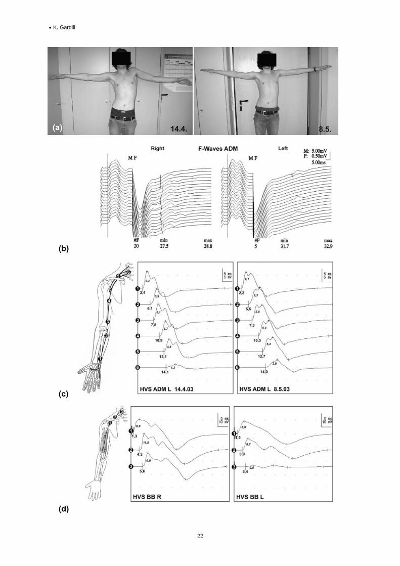
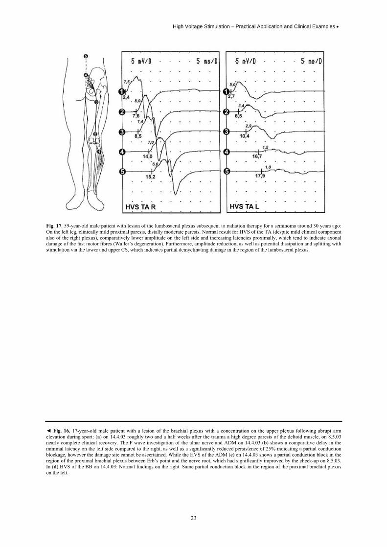
Fig. 17. 59-year-old male patient with lesion of the lumbosacral plexus subsequent to radiation therapy for a seminoma around 30 years ago: On the left leg, clinically mild proximal paresis, distally moderate paresis. Normal result for HVS of the TA (despite mild clinical component also of the right plexus), comparatively lower amplitude on the left side and increasing latencies proximally, which tend to indicate axonal damage of the fast motor fibres (Waller’s degeneration). Furthermore, amplitude reduction, as well as potential dissipation and splitting with stimulation via the lower and upper CS, which indicates partial demyelinating damage in the region of the lumbosacral plexus. ◄ Fig. 16. 17-year-old male patient with a lesion of the brachial plexus with a concentration on the upper plexus following abrupt arm elevation during sport: (a) on 14.4.03 roughly two and a half weeks after the trauma a high degree paresis of the deltoid muscle, on 8.5.03 nearly complete clinical recovery. The F wave investigation of the ulnar nerve and ADM on 14.4.03 (b) shows a comparative delay in the minimal latency on the left side compared to the right, as well as a significantly reduced persistence of 25% indicating a partial conduction blockage, however the damage site cannot be ascertained. While the HVS of the ADM (c) on 14.4.03 shows a partial conduction block in the region of the proximal brachial plexus between Erb’s point and the nerve root, which had significantly improved by the check-up on 8.5.03. In (d) HVS of the BB on 14.4.03: Normal findings on the right. Same partial conduction block in the region of the proximal brachial plexus on the left.
• K. Gardill
24
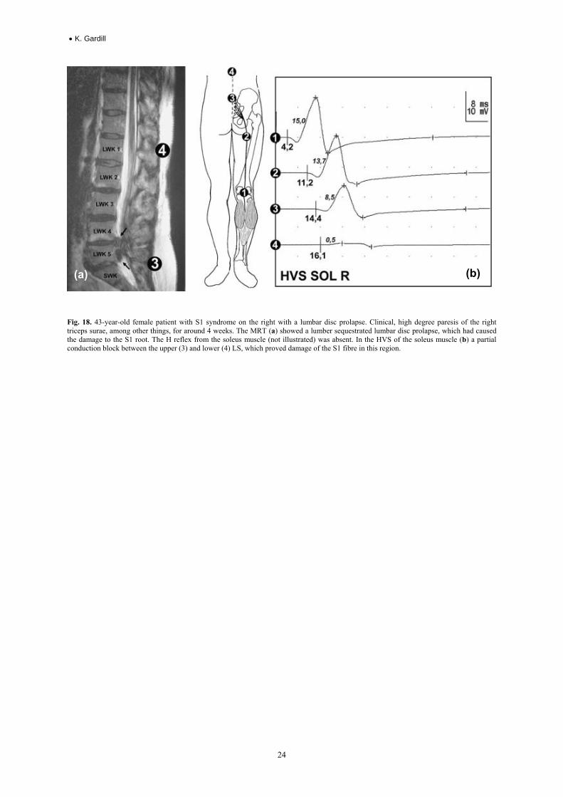
Fig. 18. 43-year-old female patient with S1 syndrome on the right with a lumbar disc prolapse. Clinical, high degree paresis of the right triceps surae, among other things, for around 4 weeks. The MRT (a) showed a lumber sequestrated lumbar disc prolapse, which had caused the damage to the S1 root. The H reflex from the soleus muscle (not illustrated) was absent. In the HVS of the soleus muscle (b) a partial conduction block between the upper (3) and lower (4) LS, which proved damage of the S1 fibre in this region.
(a) (b)
High Voltage Stimulation – Practical Application and Clinical Examples •
25
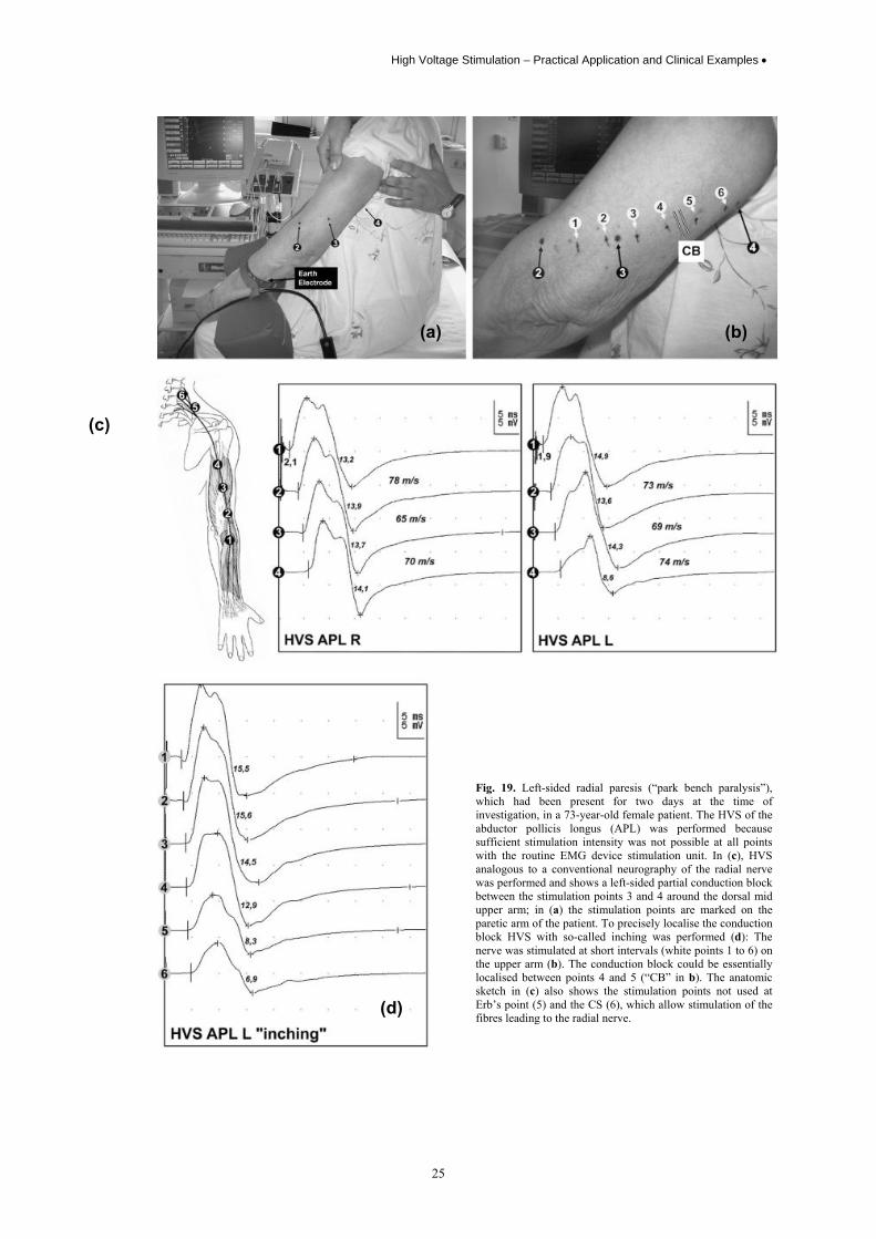
Fig. 19. Left-sided radial paresis (“park bench paralysis”), which had been present for two days at the time of investigation, in a 73-year-old female patient. The HVS of the abductor pollicis longus (APL) was performed because sufficient stimulation intensity was not possible at all points with the routine EMG device stimulation unit. In (c), HVS analogous to a conventional neurography of the radial nerve was performed and shows a left-sided partial conduction block between the stimulation points 3 and 4 around the dorsal mid upper arm; in (a) the stimulation points are marked on the paretic arm of the patient. To precisely localise the conduction block HVS with so-called inching was performed (d): The nerve was stimulated at short intervals (white points 1 to 6) on the upper arm (b). The conduction block could be essentially localised between points 4 and 5 (“CB” in b). The anatomic sketch in (c) also shows the stimulation points not used at Erb’s point (5) and the CS (6), which allow stimulation of the fibres leading to the radial nerve.
(a) (b)
(c)
(d)
• K. Gardill
26
Limitations of the method • In rare cases, no certain supramaximal stimulation can be achieved even at the customary stimulation points.
According to personal experience, these especially include the stimulation points above the LS, particularly in the caudal region (see example in Fig. 15).
• For predominantly axonal lesions, damage sites along the nerves can no longer be detected with any neurographic methods and neither therefore with HVS (after conclusion of Waller’s degeneration within two weeks). Similar observations can also be made with old (and high degree) demyelinating lesions, which can lead to (secondary) axonal damage (see example in Fig. 13)
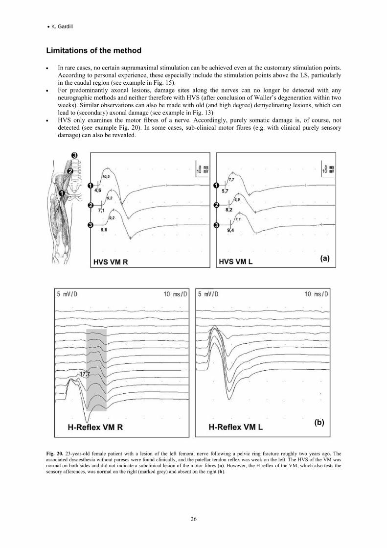
• HVS only examines the motor fibres of a nerve. Accordingly, purely somatic damage is, of course, not detected (see example Fig. 20). In some cases, sub-clinical motor fibres (e.g. with clinical purely sensory damage) can also be revealed.
Fig. 20. 23-year-old female patient with a lesion of the left femoral nerve following a pelvic ring fracture roughly two years ago. The associated dysaesthesia without pareses were found clinically, and the patellar tendon reflex was weak on the left. The HVS of the VM was normal on both sides and did not indicate a subclinical lesion of the motor fibres (a). However, the H reflex of the VM, which also tests the sensory afferences, was normal on the right (marked grey) and absent on the right (b).
(a)
(b)
High Voltage Stimulation – Practical Application and Clinical Examples •
27
Concluding remarks
The term “high voltage stimulation” suggests an unpleasant or even intolerable investigative method. After many years of personal experience with HVS, no investigation has ever been terminated by the patient on the grounds of intolerable unpleasantness. A necessary second investigation, e.g. follow-up, was also never declined by a patient.
HVS is a very valuable addition to the spectrum of neurographic investigations and can often provide vital differential diagnostic indications. Besides widespread application, standardised investigative procedures and standard values derived under unified investigative conditions would be extremely desirable and necessary.
Literature 1. Arunachalam, R., Osei-Lah, A., Mills, K.R.: Transcutaneous cervical root stimulation in the diagnosis of multifocal motor neuropathy
with conduction block. J. Neurol. Neurosurg. Psychiatr. 74 (2003) 1329–1331 2. Bischoff, C., Dengler, R., Hopf, H.C. (Ed.): EMG, NLG: Elektromyographie, Nervenleitungsuntersuchungen. Thieme-Verlag Stuttgart, 1.
Edition (2003) 3. Cappellari, A., Nobile-Orazio, E., Meucci, N., Levi Minzi, G., Scarlato, G., Barbieri, S.: Criteria for early detection of conduction block in
multifocal motor neuropathy (MMN): a study based on control populations and follow-up of MMN patients. J. Neurol. 244 (1997) 625–630
4. Claus, D.: Motorisch evozierte Potentiale (MEP). In: K. Lowitzsch et al.: Das EP-Buch. Thieme-Verlag Stuttgart, 1. Edition (2000) 173–232
5. Cornblath, D.R., Sumner, A.J., Daube, J., Gilliat, R.W., Brown, W.F., Parry, G.J., Albers, J.W., Miller, R.G., Petajan, J.: Conduction block in clinical practice. Muscle Nerve 14 (1991) 869–871
6. Gardill, K.: Ableitungstechnik und Befunde von F-Wellen und H-Reflex. Neurophysiol. Lab. 23/2 (2001) 65–86 7. Hess, C.W.: Die mittels Kortexreizung motorisch evozierten Potentiale (MEP). In: M. Stöhr et al.: Evozierte Potentiale: SEP-VEP-AEP-
EKP-MEP. Springer-Verlag Berlin Heidelberg, 3. Edition (1996) 589–654 8. Jaspert, A., Claus, D., Grehl, H., Kerling, F., Neundörfer, B.: Wertigkeit der proximalen Leitungsblockuntersuchung in der Diagnostik
entzündlicher Neuropathien. Nervenarzt 66 (1995) 445–454 9. Inaba, A., Komori, T., Yamada, K., Hirose, K., Yokota, T.: Focal conduction block in compression neuropathy of the proximal sciatic
nerve. J. Neurol. Neurosurg. Psychiatr. 58 (1995) 471–473 10. Inaba, A., Yokota, T., Komori, T, Hirose, K.: Proximal and segmental motor nerve conduction in the sciatic nerve produced by
percutaneous high voltage electrical stimulation. Electroenceph. Clin. Neurophysiol. 101 (1996) 100–104 11. Kimura J: Collision technique: physiologic block of nerve impulses in studies of motor nerve conduction velocity. Neurology 26 (1976)
680–682 12. Ludolph, A.C., Spille, M., Masur, H., Elger, C.E.: Methodik und Normwerte für die Ableitung von evozierten Muskelpotentialen nach
Stimulation über den motorischen Wurzeln. Z. EEG EMG 19 (1988) 71–74 13. Maertens de Noordhout, A., Rothwell, J.C., Thompson, P.D., Day, B.L., Marsden, C.D.: Percutaneous electrical stimulation of
lumbosacral roots in man. J Neurol Neurosurg. Psychiatr. 51 (1988) 174–181 14. Menkes, D.L., Hood, D.C., Ballesteros, R.A., Williams, D.A.: Root stimulation improves the detection of acquired demyelinating
polyneuropathies. Muscle Nerve 21 (1998) 298–308 15. Merton, P.A., Morton, H.B.: Stimulation of the cerebral cortex in the intact human subject. Nature 285 (1980) 227 16. Mills, K.R., Murray, N.M.F.: Electrical stimulation over the human vertebral column: which neural elements are excited? Electroenceph.
Clin. Neurophysiol. 63 (1986) 582–589 17. Olney, R.K. (AAEM): Consensus criteria for the diagnosis of partial conduction block. Muscle Nerve 22 Suppl. 8 (1999) 225–229 18. Plassman, B.L., Gandevia, S.C.: High voltage stimulation over the human spinal cord: sources of latency variation. J. Neurol. Neurosurg.
Psychiatr. 52 (1989) 213–217 19. Schmid, U.D., Hess, C.W., Ludin, H.P.: Methodik der elektrischen zervikalen motorischen Wurzelreizung: Einfluß der Reizparameter
und Normwerte. Z. EEG EMG 20 (1989) 39–49 20. Stöhr, M.: Somatosensible Reizantworten von Rückenmark und Gehirn (SEP). In: M. Stöhr et al.: Evozierte Potentiale: SEP-VEP-AEP-
EKP-MEP. Springer-Verlag Berlin Heidelberg, 3. Edition (1996) 23–288 Dr. Klaus Gardill, Assistant medical director of the Neurological Clinic, Aschaffenburg, Am Hasenkopf 1, D-63739 Aschaffenburg, e-mail: [email protected]