high voltage fuses - inter- · pdf filecan see the blown fuse and also automatically ... fuse...
TRANSCRIPT
2
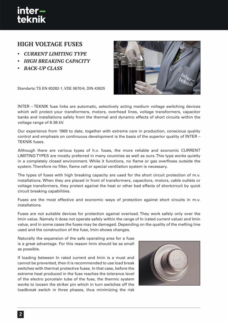
İNTER – TEKNİK fuse links are automatic, selectively acting medium voltage switching devices which will protect your transformers, motors, overhead lines, voltage transformers, capacitor banks and installations safely from the thermal and dynamic effects of short circuits within the voltage range of 6-36 kV.
Our experience from 1969 to date, together with extreme care in production, conscious quality control and emphasis on continuous development is the basis of the superior quality of İNTER – TEKNİK fuses.
Although there are various types of h.v. fuses, the more reliable and economic CURRENT LIMITING TYPES are mostly preferred in many countries as well as ours. This type works quietly in a completely closed environment. While it functions, no flame or gas overflows outside the system. Therefore no filter, flame cell or special ventilation system is necessary.
The types of fuses with high breaking capacity are used for the short circuit protection of m.v. installations. When they are placed in front of transformers, capacitors, motors, cable outlets or voltage transformers, they protect against the heat or other bad effects of shortcircuit by quick circuit breaking capabilities.
Fuses are the most effective and economic ways of protection against short circuits in m.v. installations.
Fuses are not suitable devices for protection against overload. They work safely only over the Imin value. Namely it does not operate safely within the range of In (rated current value) and Imin value, and in some cases the fuses may be damaged. Depending on the quality of the melting line used and the construction of the fuse, Imin shows changes.
Naturally the expansion of the safe operating area for a fuse is a great advantage. For this reason Imin should be as small as possible.
If loading between In rated current and Imin is a must and cannot be prevented, then it is recommended to use load break switches with thermal protective fuses. In that case, before the extreme heat produced in the fuse reaches the tolerance level of the electro porcelain tube of the fuse, the thermic system works to loosen the striker pin which in turn switches off the loadbreak switch in three phases, thus minimizing the risk
HIGH VOLTAGE FUSESCURRENT LIMITING TYPEHIGH BREAKING CAPACITYBACK-UP CLASS
Standarts: TS EN 60282-1, VDE 0670/4, DIN 43625
3
CONSTRUCTION
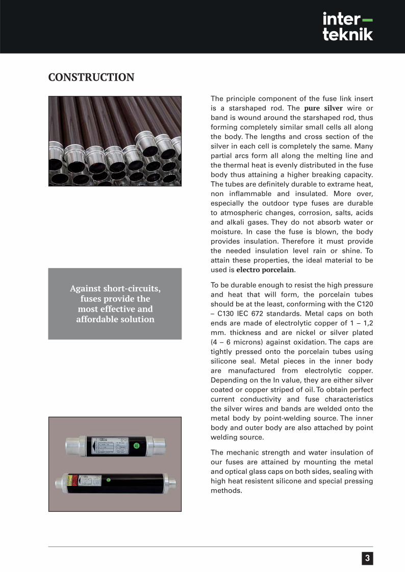
The principle component of the fuse link insert is a starshaped rod. The pure silver wire or band is wound around the starshaped rod, thus forming completely similar small cells all along the body. The lengths and cross section of the silver in each cell is completely the same. Many partial arcs form all along the melting line and the thermal heat is evenly distributed in the fuse body thus attaining a higher breaking capacity. The tubes are definitely durable to extrame heat, non inflammable and insulated. More over, especially the outdoor type fuses are durable to atmospheric changes, corrosion, salts, acids and alkali gases. They do not absorb water or moisture. In case the fuse is blown, the body provides insulation. Therefore it must provide the needed insulation level rain or shine. To attain these properties, the ideal material to be used is electro porcelain.
To be durable enough to resist the high pressure and heat that will form, the porcelain tubes should be at the least, conforming with the C120 – C130 IEC 672 standards. Metal caps on both ends are made of electrolytic copper of 1 – 1,2 mm. thickness and are nickel or silver plated (4 – 6 microns) against oxidation. The caps are tightly pressed onto the porcelain tubes using silicone seal. Metal pieces in the inner body are manufactured from electrolytic copper. Depending on the In value, they are either silver coated or copper striped of oil. To obtain perfect current conductivity and fuse characteristics the silver wires and bands are welded onto the metal body by point-welding source. The inner body and outer body are also attached by point welding source.
The mechanic strength and water insulation of our fuses are attained by mounting the metal and optical glass caps on both sides, sealing with high heat resistent silicone and special pressing methods.
Against short-circuits, fuses provide the
most effective and affordable solution
4
TYPESThe sizes of all our fuse types conform with TS EN 60282-1, DIN43625, and are suitable for indoor and outdoor use.
OPTICAL INDICATOR (TYPE: …/OPT)
The fuses with optical indicators, types H220 and H221, have a mechanism showing that the fuse is blown. When the fuse is blown, a small red cap falls into the transparent capsule at the end of the tube.
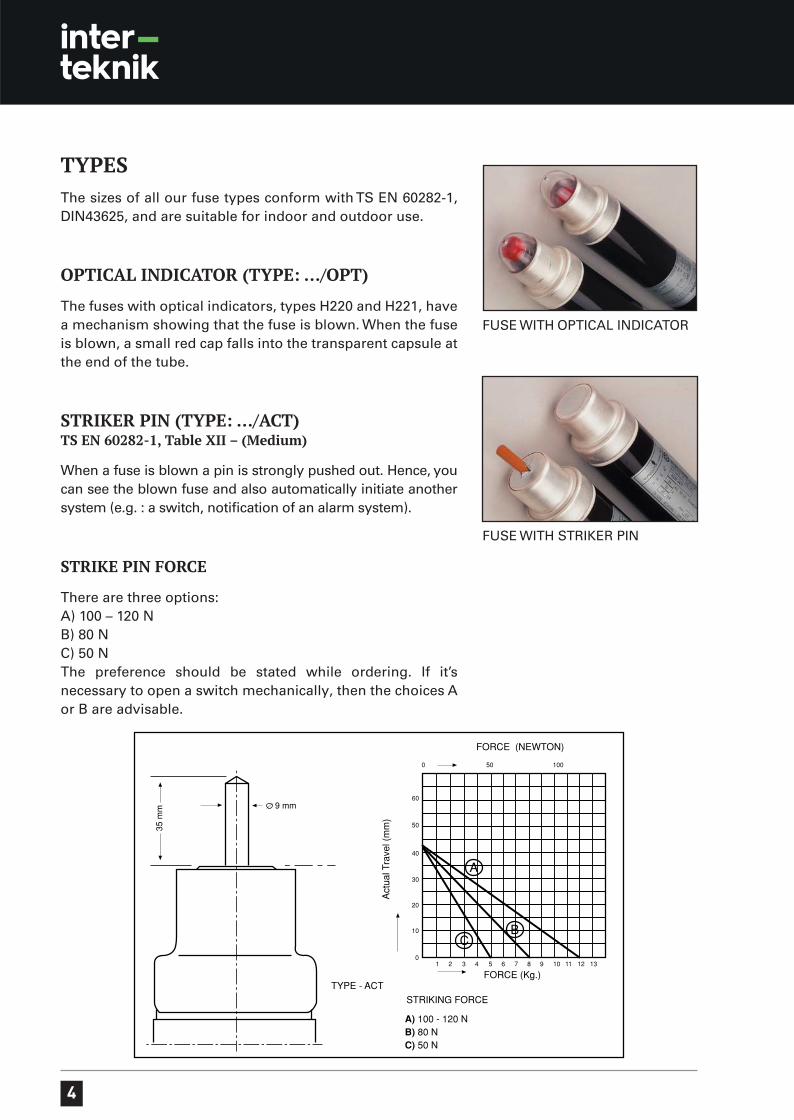
STRIKER PIN (TYPE: …/ACT)TS EN 60282-1, Table XII – (Medium)
When a fuse is blown a pin is strongly pushed out. Hence, you can see the blown fuse and also automatically initiate another system (e.g. : a switch, notification of an alarm system).
STRIKE PIN FORCE
There are three options:A) 100 – 120 NB) 80 NC) 50 NThe preference should be stated while ordering. If it’s necessary to open a switch mechanically, then the choices A or B are advisable.
FUSE WITH OPTICAL INDICATOR
FUSE WITH STRIKER PIN
5
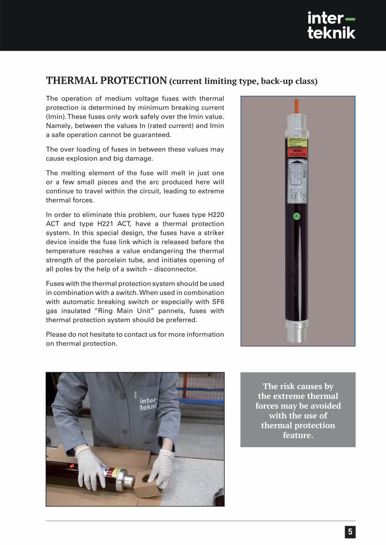
The operation of medium voltage fuses with thermal protection is determined by minimum breaking current (Imin). These fuses only work safely over the Imin value. Namely, between the values In (rated current) and Imin a safe operation cannot be guaranteed.
The over loading of fuses in between these values may cause explosion and big damage.
The melting element of the fuse will melt in just one or a few small pieces and the arc produced here will continue to travel within the circuit, leading to extreme thermal forces.
In order to eliminate this problem, our fuses type H220 ACT and type H221 ACT, have a thermal protection system. In this special design, the fuses have a striker device inside the fuse link which is released before the temperature reaches a value endangering the thermal strength of the porcelain tube, and initiates opening of all poles by the help of a switch – disconnector.
Fuses with the thermal protection system should be used in combination with a switch. When used in combination with automatic breaking switch or especially with SF6 gas insulated “Ring Main Unit” pannels, fuses with thermal protection system should be preferred.
Please do not hesitate to contact us for more information on thermal protection.
THERMAL PROTECTION (current limiting type, back-up class)
The risk causes by the extreme thermal
forces may be avoided with the use of
thermal protection feature.
6
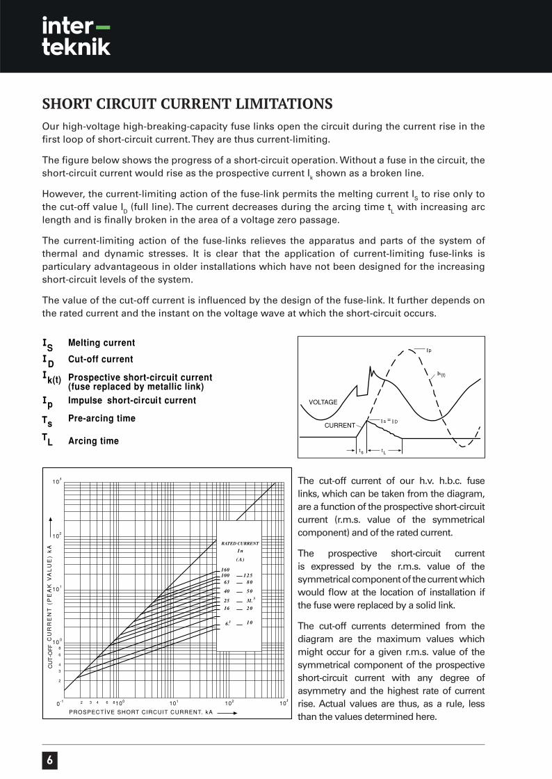
SHORT CIRCUIT CURRENT LIMITATIONSOur high-voltage high-breaking-capacity fuse links open the circuit during the current rise in the first loop of short-circuit current. They are thus current-limiting.
The figure below shows the progress of a short-circuit operation. Without a fuse in the circuit, the short-circuit current would rise as the prospective current I
k shown as a broken line.
However, the current-limiting action of the fuse-link permits the melting current IS to rise only to
the cut-off value ID (full line). The current decreases during the arcing time t
L with increasing arc
length and is finally broken in the area of a voltage zero passage.
The current-limiting action of the fuse-links relieves the apparatus and parts of the system of thermal and dynamic stresses. It is clear that the application of current-limiting fuse-links is particulary advantageous in older installations which have not been designed for the increasing short-circuit levels of the system.
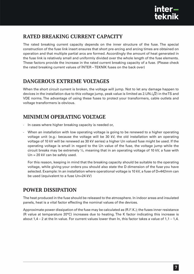
The value of the cut-off current is influenced by the design of the fuse-link. It further depends on the rated current and the instant on the voltage wave at which the short-circuit occurs.
The cut-off current of our h.v. h.b.c. fuse links, which can be taken from the diagram, are a function of the prospective short-circuit current (r.m.s. value of the symmetrical component) and of the rated current.
The prospective short-circuit current is expressed by the r.m.s. value of the symmetrical component of the current which would flow at the location of installation if the fuse were replaced by a solid link.
The cut-off currents determined from the diagram are the maximum values which might occur for a given r.m.s. value of the symmetrical component of the prospective short-circuit current with any degree of asymmetry and the highest rate of current rise. Actual values are thus, as a rule, less than the values determined here.
7
RATED BREAKING CURRENT CAPACITYThe rated breaking current capacity depends on the inner structure of the fuse. The special construction of the fuse link insert ensures that short pre-arcing and arcing times are obtained on operation and that multiple partial arcs are formed. Accordingly the amount of heat generated in the fuse link is relatively small and uniformly divided over the whole length of the fuse elements. These factors provide the increase in the rated current breaking capacity of a fuse. (Please check the rated breaking current values of İNTER – TEKNİK fuses on the back over)
DANGEROUS EXTREME VOLTAGESWhen the short circuit current is broken, the voltage will jump. Not to let any damage happen to devices in the installation due to this voltage jump, peak value is limited as 2.UN.(√2) in the TS and VDE norms. The advantage of using these fuses to protect your transformers, cable outlets and voltage transformers is obvious.
MINIMUM OPERATING VOLTAGE- In cases where higher breaking capacity is needed or,
- When an installation with low operating voltage is going to be renewed to a higher operating voltage unit (e.g.: because the voltage will be 30 kV, the old installation with an operating voltage of 10 kV will be renewed as 30 kV series) a higher Un valued fuse might be used. If the operating voltage is small in regard to the Un value of the fuse, the voltage jump while the circuit breaks may be extremely ½, meaning that in an operating voltage of 10 kV, a fuse with Un = 20 kV can be safely used.
For this reason, keeping in mind that the breaking capacity should be suitable to the operating voltage, while giving your orders you should also state the D dimension of the fuse you have selected. Example: In an installation where operational voltage is 10 kV, a fuse of D=442mm can be used (equivalent to a fuse Un=24 kV)
POWER DISSIPATIONThe heat produced in the fuse should be released to the atmosphere. In indoor areas and insulated panels, heat is a vital factor effecting the nominal values of the devices.
Approximate power dissipation of the fuse may be calculated as (R.I2.K.); the fuses inner resistance (R value at temparature 20°C) increases due to heating. The K factor indicating this increase is about 1,4 – 2 at the In value. For current values lower than In, this factor takes a value of 1,1 – 1,4.
8
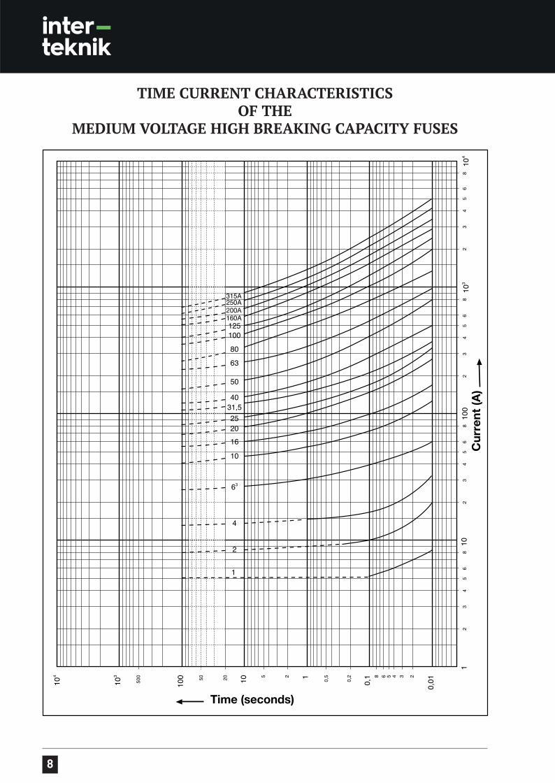
TIME CURRENT CHARACTERISTICSOF THE
MEDIUM VOLTAGE HIGH BREAKING CAPACITY FUSES
9
SELECTIONS
RATED VOLTAGE
Must be properly selected in accordance with the operational voltage.
RATED BREAKING CURRENTProper fuse selection according to the short circuit load of the network is important. In some special occasions, if necessary, a fuse of a higher voltage group may be selected or two fuses may be connected in serial, thus obtaining a higher rated breaking current capacity.
RATED CURRENTThis value denotes the naming of the fuse. Essentially the selection of the fuse according to the purpose and the place of use is very important. Heat is one of the most important factors. For example in the protection of a transformer, if a fuse of In=6 A is suitable outdoors, when the same transformer is used in a completely closed indoor area, then a fuse In=10 A may be necessary. In extreme cases where higher current values are necessary, two fuses with the same value connected parallel can be used. But as the two fuses standing side by side will give heat to each other, a specific tolerance level should be set.
DERATING FACTORThe rated current is the current which a fuse link can carry continuously without altering the time/current characteristic curve. At higher ambient temperatures as well as higher power losses generated by fuses of very high rated currents, it is necessary to pay special attention to derating factors.
Depending on usage conditions and due to the overheating of the fuse body, it is advisable to reevaluate the choice of fuse rating and use a fuse with a greater In value.
In fuses that operate with melting fuse elements, the heat of the fuse body is the main factor that effects the functioning of the fuse. As it functions, the heat produced in the fuse should be transferred to the atmosphere in an effective way. If the body of a used. For example, under normal conditions a fuse In=40 A might be suitable for the protection of a transformer, but if because of environmental factors the fuse heats excessively, then a fuse of In=50 or 63 A should be used.
As the plants of our day are huge and growing in size, they require fuses with very high In values for their protection. Meanwhile, as the In value of fuses increase, due to physical limitations of material and production methods, it becomes very difficult to keep the heat of the fuse at normal temperatures. Therefore, especially under these circumstances special attention should be given to the DERATING FACTOR.
Due to their high starting currents, in the protection of electrical appliances such as motors, transformers or capacitors, fuses with in In values should be selected. In other words, under normal operating conditions the current passing through the fuse will be approximately half, under 25% overload it will be about 75% of the In value of the fuse. Generally the nominal current of the fuse should be 2 or 3 times larger then that of the normal circuit current. It is important to keep this fact in mind.
This means the fuses will warm less. As you evaluate, special attention should be given to this issue. For this reason, on the labels of these fuses both current values are indicated. For example “250 RC 160” means:- the nominal current of the fuse In=250 A. (the starting current is taken into consideration)- the current value of the continuous current through the circuit RC (rated current) is 160 A.
10
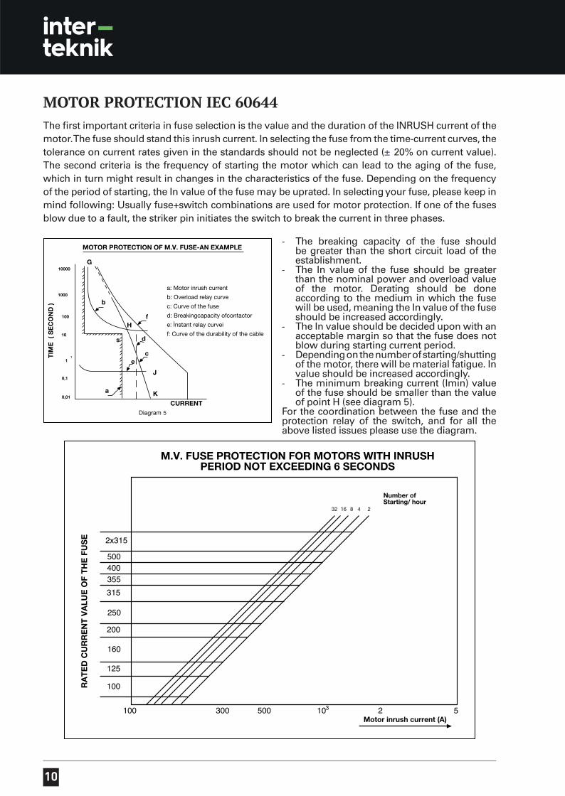
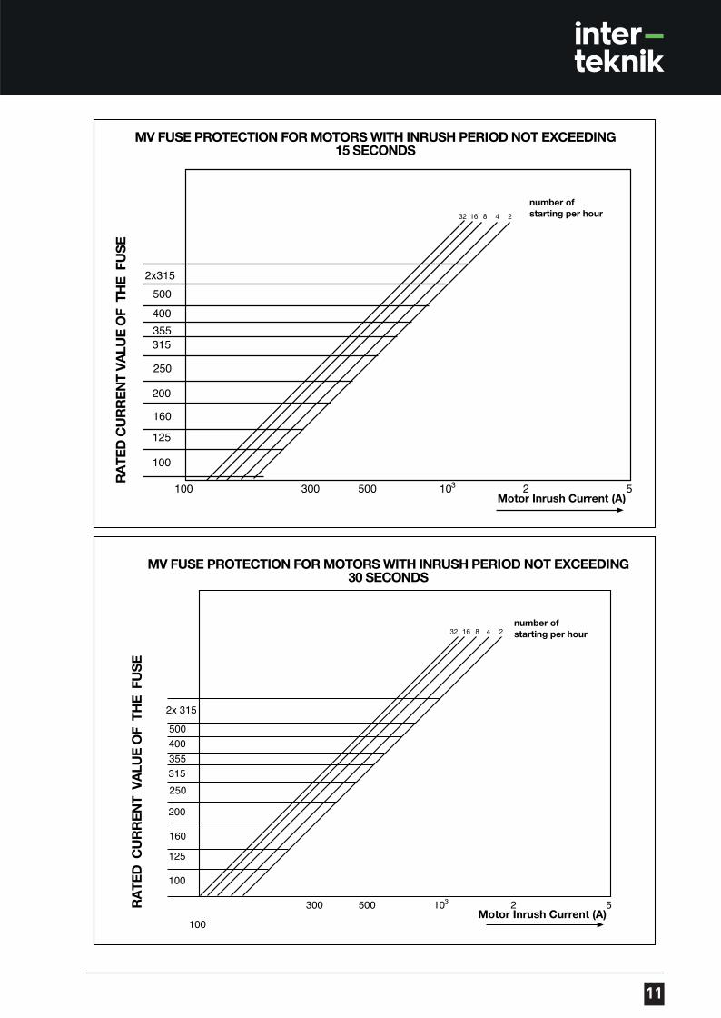
MOTOR PROTECTION IEC 60644The first important criteria in fuse selection is the value and the duration of the INRUSH current of the motor. The fuse should stand this inrush current. In selecting the fuse from the time-current curves, the tolerance on current rates given in the standards should not be neglected (± 20% on current value). The second criteria is the frequency of starting the motor which can lead to the aging of the fuse, which in turn might result in changes in the characteristics of the fuse. Depending on the frequency of the period of starting, the In value of the fuse may be uprated. In selecting your fuse, please keep in mind following: Usually fuse+switch combinations are used for motor protection. If one of the fuses blow due to a fault, the striker pin initiates the switch to break the current in three phases.
- The breaking capacity of the fuse should be greater than the short circuit load of the establishment.
- The In value of the fuse should be greater than the nominal power and overload value of the motor. Derating should be done according to the medium in which the fuse will be used, meaning the In value of the fuse should be increased accordingly.
- The In value should be decided upon with an acceptable margin so that the fuse does not blow during starting current period.
- Depending on the number of starting/shutting of the motor, there will be material fatigue. In value should be increased accordingly.
- The minimum breaking current (Imin) value of the fuse should be smaller than the value of point H (see diagram 5).
For the coordination between the fuse and the protection relay of the switch, and for all the above listed issues please use the diagram.
5
11
12
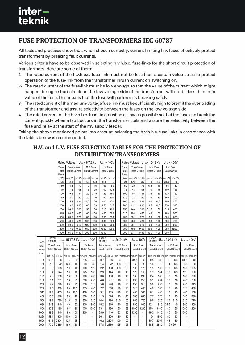
FUSE PROTECTION OF TRANSFORMERS IEC 60787All tests and practices show that, when chosen correctly, current limiting h.v. fuses effectively protect transformers by breaking fault currents.
Various criteria have to be observed in selecting h.v.h.b.c. fuse-links for the short circuit protection of transformers. Here are some of them:1- The rated current of the h.v.h.b.c. fuse-link must not be less than a certain value so as to protect
operation of the fuse-link from the transformer inrush current on switching on.2- The rated current of the fuse-link must be low enough so that the value of the current which might
happen during a short-circuit on the low voltage side of the transformer will not be less than Imin value of the fuse. This means that the fuse will perform its breaking safely.
3- The rated current of the medium-voltage fuse link must be sufficiently high to premit the overloading of the transformer and assure selectivity between the fuses on the low voltage side.
4- The rated current of the h.v.h.b.c. fuse-link must be as low as possible so that the fuse can break the current quickly when a fault occurs in the transformer coils and assure the selectivity between the fuse and relay at the start of the mv supply feeder.
Taking the above mentioned points into account, selecting the h.v.h.b.c. fuse links in accordance with the tables below is recommended.
H.V. and L.V. FUSE SELECTING TABLES FOR THE PROTECTION OF DISTRIBUTION TRANSFORMERS
13
FUSE PROTECTION OF CAPACITOR BANKSThe existence of numerous types of electrical facilities and unknown circuit parameters usually complicates fuse selection. When selecting, keep in mind the following criteria:
- The In value of the fuse should be high enough to withstand the continuous maximum load current and the allowable harmonic content.
- The In value of the fuse should be able to tolerate the inrush value of the condenser bank.
- Voltage increases caused by temporary situations should not be neglected and for security purposes, a higher current class fuse should be selected.
- As for practical information, the In value of the fuse should not be lower than 1,6 – 2 times that of the condenser’s full load current value.
WIRE AND LINE PROTECTIONIt should not be forgotten that wires and lines will be exposed to overloading from time to time. This situation may cause overloads between the In value and Imin value of the fuse, eventually causing extreme heating and damage. For this reason the fuse should be selected according to the maximum load that the cable or line can carry.
OTHER POINTS- It is not correct to use a fuse that has been dropped or exposed to any sort of impact without
testing it.
- In a three – phase installation, unless you are definitely sure that only the blown fuse was exposed to a faulty current, all three must be replaced, because the fuses that are not blown also might have reached a point very close to functioning and their characteristics might have changed.
- As a precaution, the blown fuse should be changed 5 – 10 minutes after it has blown.
VOLTAGE TRANSFORMER PROTECTIONBecause of the low capacity of voltage transformers, h.v. fuses cannot protect the voltage transformer from their own default currents effectively. More often, they are used to seperate the defected voltage transformer from the system. The principle in choosing the fuse is to use a fuse big enough to endure the inrush voltage of the transformer. This means that the fuse should be at the most I
n=1-2 A. The very
thin melting line used in the fuses with small In values may lead to a “corona” effect. Therefore, the fuse should definitely be used as far away from earthed metal parts as possible.
THINGS TO INDICATE WHILE ORDERING Type : H220 – H221Indicator : OPT (Optical) or ACT (striker pin)If ACT, the force of the striker pin : F=50 N, F=80 N, F=120 NTherml protection : TRMRated voltage (Un) kV : from the tableLength (D) mm : from the tableRated current (In) A : from the table
Example 1- H220/ACT F=80 N Example 2- H221/OPT Un=36 kV D=537 mm Un=12 kV D=442 mm
In=40 A I1= 31,5 kA In= 160 A I
1=63 kA
14
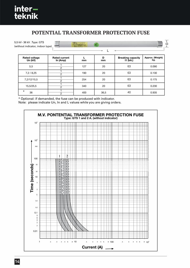
POTENTIAL TRANSFORMER PROTECTION FUSE
63
63
63
63
40
15
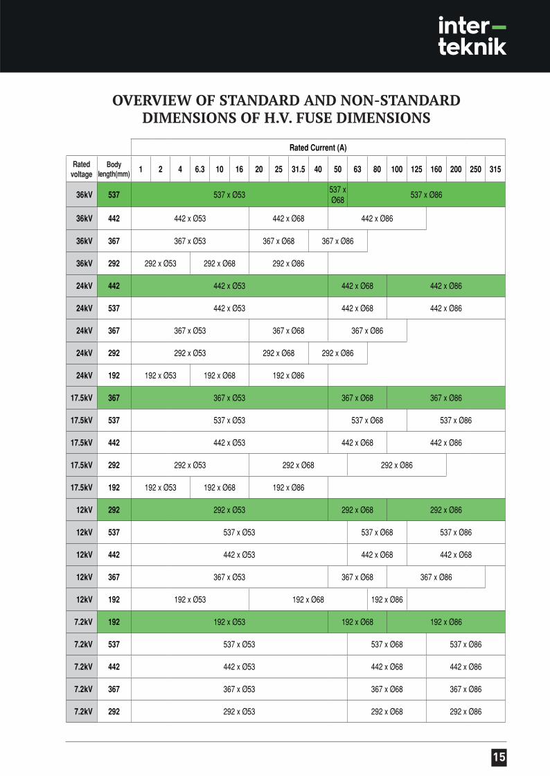
OVERVIEW OF STANDARD AND NON-STANDARD DIMENSIONS OF H.V. FUSE DIMENSIONS
Rated Current (A)
Ratedvoltage
Bodylength(mm) 1 2 4 6.3 10 16 20 25 31.5 40 50 63 80 100 125 160 200 250 315
36kV 537 537 x Ø53537 xØ68
537 x Ø86
36kV 442 442 x Ø53 442 x Ø68 442 x Ø86
36kV 367 367 x Ø53 367 x Ø68 367 x Ø86
36kV 292 292 x Ø53 292 x Ø68 292 x Ø86
24kV 442 442 x Ø53 442 x Ø68 442 x Ø86
24kV 537 442 x Ø53 442 x Ø68 442 x Ø86
24kV 367 367 x Ø53 367 x Ø68 367 x Ø86
24kV 292 292 x Ø53 292 x Ø68 292 x Ø86
24kV 192 192 x Ø53 192 x Ø68 192 x Ø86
17.5kV 367 367 x Ø53 367 x Ø68 367 x Ø86
17.5kV 537 537 x Ø53 537 x Ø68 537 x Ø86
17.5kV 442 442 x Ø53 442 x Ø68 442 x Ø86
17.5kV 292 292 x Ø53 292 x Ø68 292 x Ø86
17.5kV 192 192 x Ø53 192 x Ø68 192 x Ø86
12kV 292 292 x Ø53 292 x Ø68 292 x Ø86
12kV 537 537 x Ø53 537 x Ø68 537 x Ø86
12kV 442 442 x Ø53 442 x Ø68 442 x Ø68
12kV 367 367 x Ø53 367 x Ø68 367 x Ø86
12kV 192 192 x Ø53 192 x Ø68 192 x Ø86
7.2kV 192 192 x Ø53 192 x Ø68 192 x Ø86
7.2kV 537 537 x Ø53 537 x Ø68 537 x Ø86
7.2kV 442 442 x Ø53 442 x Ø68 442 x Ø86
7.2kV 367 367 x Ø53 367 x Ø68 367 x Ø86
7.2kV 292 292 x Ø53 292 x Ø68 292 x Ø86

For detailed information please visit our website. Meanwhile, we’re glad to offer our technical expertise whenever required, so you are most welcome to contact us for your technical inquiries.
www.inter-teknik.com.tr
Head Of ce
Kemankeş Cad. Fransız Geçidi
İş Merkezi No:53 Kat:1 C Blok D:16
Karaköy, Beyoğlu / İstanbul-TR
T +90 212 249 84 58 / 244 32 49
Factory
Şekerpınar Mah. Marmara Geri
Dönüşümcüler Yapı Koop. Defne Sok.
No:3 Çayırova / Kocaeli-TR
T +90 262 658 93 11