high purity chemical valve - steven engineering · high purity chemical valve series lv n.c. 459...
TRANSCRIPT

Series LVC/LVA/LVHHigh Purity Chemical Valve
Integral Fittings/Threaded Ports/Manual Operation (Integral Fittings/Threaded Ports)
� N.C./N.O. with same configuration/Double acting� Compatible with 100°C fluid temperature
� Locking and non-locking types available
Air Operated Type
Integral Fittings Series LVC
� Diaphragm material PTFE, EPR, NBR are selectable
Series LVA
Series LVC
Series LVH
New PFA/
Stainless steel/
PPSNew PFA/
Stainless steel/
PPSNew PFA/
Stainless steel/
PPS
Body material:Body material:
New PFANew PFANew PFABody material:
Body material:
New PFA/
Stainless steel/
PPSNew PFA/
Stainless steel/
PPSNew PFA/
Stainless steel/
PPS
Body material:Body material:
Air Operated Type
Threaded Ports Series LVA
Manual Operation Series LVHIntegral fitting type/Threaded type
P.461
P.471
P.481
457
LVC
LVA
LVH
LVD
LVQ
LQ1
LVN
TL/TIL
LQ3
Courtesy of Steven Engineering, Inc.-230 Ryan Way, South San Francisco, CA 94080-6370-Main Office: (650) 588-9200-Outside Local Area: (800) 258-9200-www.stevenengineering.com
LVCLVCLVC LVALVALVA LVHLVHLVH
PAT.
Medicalequipment
Cleaningequipment
Pharma-ceutical manu-
facturing
AnalyticalInstruments
ChemicalsIC manu-facturing
linesFood
processing
Cleaningequipment
IC manu-facturing
AnalyticalInstruments
For shut off
For airbleeding
ChemicalsMedical
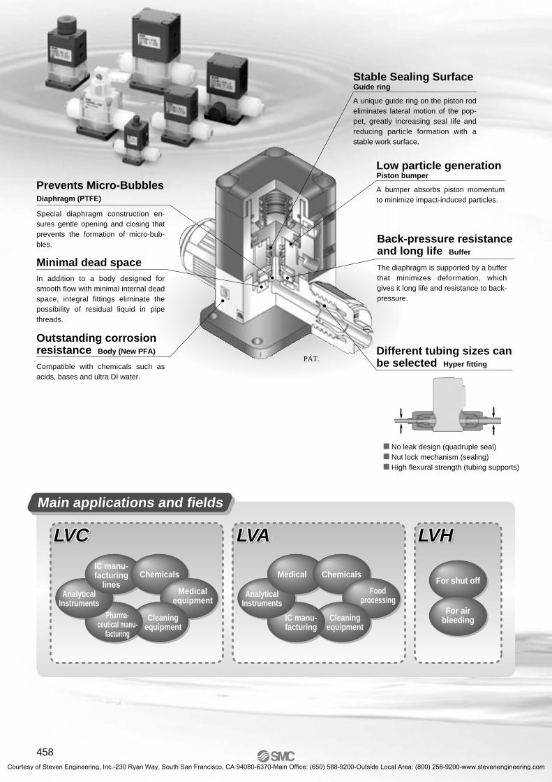
Minimal dead space
Outstanding corrosion resistance Body (New PFA)
Prevents Micro-Bubbles Diaphragm (PTFE)
Special diaphragm construction en-sures gentle opening and closing that prevents the formation of micro-bub-bles.
In addition to a body designed for smooth flow with minimal internal dead space, integral fittings eliminate the possibility of residual liquid in pipe threads.
Compatible with chemicals such as acids, bases and ultra DI water.
Stable Sealing Surface Guide ring
A unique guide ring on the piston rod eliminates lateral motion of the pop-pet, greatly increasing seal life andreducing particle formation with a stable work surface.
Different tubing sizes can be selected Hyper fitting
� No leak design (quadruple seal)� Nut lock mechanism (sealing)� High flexural strength (tubing supports)
Low particle generation Piston bumper
Back-pressure resistance and long life Buffer
A bumper absorbs piston momentum to minimize impact-induced particles.
The diaphragm is supported by a buffer that minimizes deformation, which gives it long life and resistance to back-pressure.
Main applications and fields
458Courtesy of Steven Engineering, Inc.-230 Ryan Way, South San Francisco, CA 94080-6370-Main Office: (650) 588-9200-Outside Local Area: (800) 258-9200-www.stevenengineering.com

N.C.
N.O.
N.C.
N.C.
N.C.
N.C.
N.C. N.O. Doubleacting
N.C. Double acting
Double acting
Double acting
N.C.
N.C.
Singletype
UnitSingle type Unit
Doubleacting
Double acting
Double acting
Double acting
Inch
ModelOrifice diameter
MetricTubing O.D.
SymbolType
Basic type
With flow rateadjustment
With bypass
With flow rateadjustment& bypass
Suck back
With indicator
N.C.
Manifold(5 stations max.)
Valve type
ModelOrifice diameterNote 1)
Body material
SymbolTypeValve type
PA
B A
PA
B A
AB
P PP
AB
PA
PBB A
PA
B A
PA
PBB A
PA
B A
PA
PBB A
PB
PB
B A
PA
B A
PA
B A
PA
ARP
3 port
N.C.N.C.
Basic type
With flow rateadjustment
With bypass
With flow rateadjustment& bypass
With indicator
Manifold(5 stations max.)
N.C. N.O.
N.C.
N.C.
N.C.
N.C.
Port size
N.C.
N.C.
N.O.
N.C.
N.C.
N.C.
LVA1� LVA2� LVA3� LVA4� LVA6�
1/8 1/4
ø21/8 1/4
ø41/4 3/8
ø83/8 1/2
ø121
ø22LVA5�
1/2 3/4
ø20
PA
B A
PA
B A
PA
PBB A
PA
B A
PA
PBB A
PA
B A
PA
PBB A
PA
B APB
PB
B A
PA
B A
PA
ARP N.C.
3 port
Integral Fitting Type Series LVCAir Operated
P.461
Air OperatedThreaded Type Series LVA P.471
PPSPFA
Stainless steel (SUS316)
Note 1) Refer to the page 471 for the ap-plicable optional body materials.
Note 2) Only PFA is applicable as a body material.
Note 2)
LVC2�ø4
3, 4, 61/8, 3/16, 1/4
LVC3�ø8
6, 8, 101/4, 3/8
LVC4�ø10
10, 123/8, 1/2
LVC6�ø22
19, 253/4, 1
LVC5�ø16
12, 191/2, 3/4
Doubleacting
Doubleacting
Doubleacting
Doubleacting
DoubleactingDoubleacting
Doubleacting
Doubleacting
High Purity Chemical Valve Series LV
N.C.
459
LVC
LVA
LVH
LVD
LVQ
LQ1
LVN
TL/TIL
LQ3
Courtesy of Steven Engineering, Inc.-230 Ryan Way, South San Francisco, CA 94080-6370-Main Office: (650) 588-9200-Outside Local Area: (800) 258-9200-www.stevenengineering.com

Metric
Manually Operated Series LVH P.481Integral Fitting Type
LVH20ø4
3, 4, 61/8, 3/16, 1/4
LVH30ø8
6, 8, 101/4, 3/8
LVH40ø10
10, 123/8, 1/2
Non-locking Locking
Non-locking Locking
N.C.
Manifold(5 stations max.)
Basic typeAB AB
N.C.
Manifold(5 stations max.)
Threaded Type
Basic type
LVH20ø4
1/8 1/4 1/4 1/4
Stainless steel(SUS316) PPS PFA
LVH30ø8
LVH40ø12
1/4 3/8 3/8 3/8
Stainless steel(SUS316) PPS PFA
3/8 1/2 1/2 1/2
Stainless steel(SUS316) PPS PFA
AB AB
Inch
ModelOrifice diameter
ModelOrifice diameter
MaterialPort size
Tubing O.D.SymbolType
SymbolType
Valve type
Valve type
Series LV
460Courtesy of Steven Engineering, Inc.-230 Ryan Way, South San Francisco, CA 94080-6370-Main Office: (650) 588-9200-Outside Local Area: (800) 258-9200-www.stevenengineering.com

How to Order Valves (Single Type)
Connecting tubing O.D.
ø3ø4ø6ø8ø10ø12ø19ø25
1/83/161/43/81/23/41
Body class2 3 4 65
0304060810121925
03050711131925
Symbol
Metric sizes
Inch sizes
Applicable tubing size
ApplicationPorts A & B same size
Different diameter tub-ings can be selected within the same body class.
SymbolNil
Port B (OUT) different dia. size
NoneWith flow rate adjustment
With bypassWith flow rate adjustment & bypass
With indicator
Nil1234
Option
Body class2
3, 4, 5, 63, 4, 5, 6
Thread typeM5
Rc 1/8NPT 1/8
Symbol
Nil
N
Pilot port thread type
Material
Body class
LVC 2 0 06S
Symbol23456
Body class23456
Orifice dia.ø4ø8
ø10ø16ø22
Valve type LQ2integral
fitting012
N.C.N.O.
Double acting
Body
PFA
PFA
PFA
Dia-phragm
PTFE
PTFE
PTFE
Note
–
Ammonium hydroxide compatible
Actuator sectionEnd plate
PPS
PVDF
PPS
Symbol
Nil
F
N
Variations
InchValve type
ModelOrifice diameter
MetricTubing O.D.
SymbolType
Basic type
Note) Refer to “Variations” in the table below for option combinations.Options can not be combined each other.Note) Refer to variations in
the table below for valve type combina-tions.
Note) Applicable fittings for body class 6 is LQ1.
1 2Applicable option
3 4
Hydrofluoric acid compatible(Only LVC40, 50 type)
Basic size With reducer
Refer to the applicable tubing table to the left.
LVC20
ø4
3, 4, 6
1/8, 3/16, 1/4
LVC30
ø8
6, 8, 10
1/4, 3/8
LVC40
ø10
10, 12
3/8, 1/2
LVC60
ø22
19, 25
3/4, 1
LVC50
ø16
12, 19
1/2, 3/4
With flowrateadjust-ment
With bypass
With indicator
With flow rate adjust-ment & bypass
PA
B A
PA
B A
PB
PBB A
N.C. N.O. Doubleacting
PA
B A
N.C. Doubleacting
PA
PBB A
N.C. Doubleacting
PA
B A
PA
PBB A
N.C. Doubleacting
PA
B A
PA
PBB A
PA
B A
N.C.
N.C.
N.O.
N.C.
N.C.
N.C.
N.C.
Doubleacting
Doubleacting
Doubleacting
Doubleacting
461
Air Operated TypeIntegral Fitting Type (Hyper Fittings)
Series LVCLVC
LVA
LVH
LVD
LVQ
LQ1
LVN
TL/TIL
LQ3
Courtesy of Steven Engineering, Inc.-230 Ryan Way, South San Francisco, CA 94080-6370-Main Office: (650) 588-9200-Outside Local Area: (800) 258-9200-www.stevenengineering.com

Different Diameter Tubing Applicable with Reducer
Model LVC206
1/4ø48.40.35
M5 Rc 1/8, NPT 1/8
LVC30103/8ø8
40.81.7
0 to 0.50.3 or less0.4 or less
0 to 0.40.2 or less0.3 or less
1
0 (with water pressure)0.3 to 0.5
0 to 1000 to 60
LVC40121/2ø10602.5
LVC60251
ø221928
LVC50193/4ø161446
0.09 0.23 0.42 1.000.86
Orifice diameter
Withstand pressure (MPa)Operating pressure (MPa)
Valve leakage (cm3/min)Pilot air pressure (MPa)Pilot port sizeFluid temperature (°C)Ambient temperature (°C)Mass (kg)
Metric sizeInch size
Av x 10-6m2
Cv
N.C./N.O.Double acting
Tubing O.D.
Back pressure(MPa)
Different diameter tubing can be selected (within a body class) by using a nut andinsert bushing (reducer). With reducer
Note) Refer to page 489 for information on changing tubing sizes.
Note 1) Contact SMC if the valve is to be used with vacuum and B → A flow.
Bodyclass
23456
43 1/8 3/166 1/410 3/812 19 25 1/2 3/4 18
Tubing O.D.
Metric sizes Inch sizes
Specific Product Precautions
1. Connect tubing with special tools.Refer to the pamphlet “High-Purity Fluoropolymer Fittings HYPER FIT-TING®/Series LQ1, 2 Work Procedure Instructions” (M-E05-1) for connecting tubing and special tools. (Download-able from our web site.)
2. Tighten the nut to the end surface of the body. As a guide, refer to the proper tightening torques shown below.
Piping
Caution
Tightening torque for pipingBody class Torque (N·m)
1.5 to 2.0
3.0 to 3.5
7.5 to 9.0
11.0 to 13.0
5.5 to 6.0
23456
Be sure to read before handling. Refer to front matters 42 and 43 for Safety Instructions, and pages 491 and 492 for High Purity Chemical Valve Precautions.
Flowcharacteristics
Caution
Series LVC
Standard Specifications
462Courtesy of Steven Engineering, Inc.-230 Ryan Way, South San Francisco, CA 94080-6370-Main Office: (650) 588-9200-Outside Local Area: (800) 258-9200-www.stevenengineering.com

Single type
Unit type
� With flow rate adjustmentThe flow rate is adjusted by controlling the diaphragm stroke.
� With bypass
A change of volume inside the suck back valve pulls in liq-uid at the end of the nozzle to prevent dripping.
Options
Model
(3), (4), 6
(1/8), (3/16), 1/4
1
0 to 0.2
0.1
0.3 to 0.5
M5
0 to 100
0 to 60
LVC23U
ø3
4.8
0.2
0.16
LVC23
—
—
—
0.08
Body class
LQ2 integral fitting
LVC 2 3 S 06
Symbol2
Body class2
Body typeNilU
Single typeUnit type with 2 way valve
Applicable tubing size
Valve type3 Suck back valve
Adjustment knobAdjusts the flow rate.
Lock nutLocks the adjustmentknob position.
Adjustment knobAdjusts the amount of suck back.
Lock nutLocks the adjustmentknob position.
Suck back body
Symbol
Lock nutLocks the adjustmentknob position.
How to Order
Connectingtubing O.D.
ø3ø4ø6
1/83/161/4
Body class2
030406
030507
Symbol
Metric sizes
Inch sizes
AB
P
PP
AB
ApplicationPorts A & B same size
SymbolNil
Adjustment knobAdjusts the flow rate.
Adjustment knobAdjusts the amount of suck back.
Lock nutLocks the adjustmentknob position.
Lock nutLocks the adjustmentknob position.
Symbol
Adjustment knobAdjusts the flow rate.
Standard Specifications
Orifice diameter
Withstand pressure (MPa)
Operating pressure (MPa)
Maximum suck back volume (cm3)
Pilot air pressure (MPa)
Pilot port size
Fluid temperature (°C)
Ambient temperature (°C)
Mass (kg)
Tubing O.D.Note 1)
Flowcharacteristics
Metric sizes
Inch sizes
Av x 10-6m2
Cv
Note 1) Different diameter tubing shown in ( ) can be selected when used with a reducer. Refer to page 489 for details.
Port B (OUT)different dia. size
Basic size With reducer
Refer to the app l i cab le tubing in the table below.
Different diameter tubing can be se-lected within the same body class.
A small amount of fluid from the inlet side is allowed to flow continuously to the outlet side by providing a bypass inside the body.
463
Series LVC
Suck Back
Air Operated TypeIntegral Fitting Type (Hyper Fittings)
LVC
LVA
LVH
LVD
LVQ
LQ1
LVN
TL/TIL
LQ3
Courtesy of Steven Engineering, Inc.-230 Ryan Way, South San Francisco, CA 94080-6370-Main Office: (650) 588-9200-Outside Local Area: (800) 258-9200-www.stevenengineering.com

No.
1
2
3
4
5
6
7
8
9
Description Material
Actuator section
Body
Diaphragm
End plate
Insert bushing
Nut
Collar
Flow rate adjuster section
Indicator
PPS
PFA
PTFE
PPS
PFA
PFA
PFA
PPS
PP
Option
PVDF
—
—
PVDF
—
—
—
—
—
q
ew
q
ew
q
ew
r t y
ui
i
t y
i ii
e
o
e
q
ty
rw
PA
AB
PB
PA
AB
PB
PA
AB
PB
PA
AB
PB
P
P
e
e
P
ty
w r
B A AB
AB
AB
Series LVC
Construction
Standard typeN.C. type N.O. type Double acting type
With reducer With flow rate adjustment With bypass
Suck back (single type) Suck back (unit type)
With indicator
464
Parts list
Courtesy of Steven Engineering, Inc.-230 Ryan Way, South San Francisco, CA 94080-6370-Main Office: (650) 588-9200-Outside Local Area: (800) 258-9200-www.stevenengineering.com

Model
LVC2�LVC3�LVC4�LVC5�LVC6�
A30
36
46
58
58
B30
47
60
75
75
F 79
106
131
154
165
D44
56
68
84
84
H13
17.5
18
27.5
27.5
J4
7.5
8
8
8
K20
34
42
56
56
L37
46
57
71
71
M3.5
5.5
5.5
6.5
6.5
QM5 x 0.8
RN23.5
39
48
62
71
C54.5
79
96
129
138
E11
16.5
22
26
32
G28.5
43
55
68
77
(mm)
M3 x 0.5
Rc 1/8NPT 1/8
Rc 1/8NPT 1/8
B
K
C
N
AL D
E
J
GH
4 x øM
Sensor (Breathing port) R
SMC
AB
PB
PA
Series LVC
Basic type
Dimensions
2 x Q
(F)
465
Dimensions
Air Operated TypeIntegral Fitting Type (Hyper Fittings)
LVC
LVA
LVH
LVD
LVQ
LQ1
LVN
TL/TIL
LQ3
Courtesy of Steven Engineering, Inc.-230 Ryan Way, South San Francisco, CA 94080-6370-Main Office: (650) 588-9200-Outside Local Area: (800) 258-9200-www.stevenengineering.com

3037
3.5
44
W
30
12.54
45
4.5
50
61
A B
51
A
PB
PA
SMC
BAB
AB
Model
LVC2�LVC3�LVC4�LVC5�LVC6�
S12.5
24
29
34.5
36
(mm)
Model
LVC3�LVC4�LVC5�
S24
29
34.5
T49.5
54.5
60.5
(mm)
Model
LVC3�LVC4�LVC5�
T49.5
54.5
60.5
(mm)
Model
LVC20LVC30LVC40LVC50LVC60
W64
90
110.5
147
156
(mm)
PB
PA
SMC
PB
PA
SMC
30
A B
51
12.5
45
4
30 44
20
37
SMC
SMC SMC SMC
AB
Series LVC
With flow rate adjustment With bypass
Dimensions
(Max
. S)
(Max. T)
With indicatorWith flow rate adjustment & bypass
(Max
. S)
(Max. T)
Suck back (Unit type)Suck back (Single type)
(78)
(Max
. 11.
5)4 x ø3.5
M5 x 0.8M5 x 0.8
(110)
(Max
. 11.
5)
M5 x 0.8
Dimensions
Dimensions
Dimensions
Dimensions
466Courtesy of Steven Engineering, Inc.-230 Ryan Way, South San Francisco, CA 94080-6370-Main Office: (650) 588-9200-Outside Local Area: (800) 258-9200-www.stevenengineering.com

2 stations
5 stations
02
05
Manifold stations
Tubing sizePlugØ61/4"Ø8
Ø103/8"Ø103/8"Ø121/2"Ø121/2"
Ø19, 3/4"Ø121/2"
Ø19, 3/4"
Body class
2
3
4
5
2 to 5Symbol
00060708101110111213121319121319
Tubing size for P port and L side connection
Tubing sizeØ3, 1/8"
Ø43/16"
Ø61/4"Ø61/4"Ø8
Ø103/8"Ø103/8"Ø121/2"Ø121/2"
Ø19, 3/4"
Body class
2
3
4
5
Symbol0304050607060708101110111213121319
Tubing size
Tubing size
PlugØ61/4"Ø8
Ø103/8"Ø103/8"Ø121/2"Ø121/2"
Ø19, 3/4"Ø121/2"
Ø19, 3/4"
Body class
2
3
4
5
2 to 5
SymbolNil00060708101110111213121319121319
Tubing size for P port and R side connectionBody class
LLC 2 A 02 11S
Symbol2345
Body class2345
Base type
LQ2 integral fitting
A Stacking type
NoneWith flow rate adjustment
With indicator
Nil14
Option
Body class2
3/4/53/4/5
Symbol
Nil
N
Pilot port thread type
Body class
LVC 2 0 07S
Symbol2345
Body class2345
Orifice dia.ø4ø8ø12ø20
Valve type
A
012
N.C.N.O.
Double acting
Thread typeM5
Rc 1/8NPT 1/8
Body typeA Stacking type for manifold
Model LLC2A
3/8
1/4
LLC3A
1/2
3/8
LLC4A
3/4
1/2
Stacking type
Common IN/Individual OUT
2 to 5 stations
LLC5A
3/4
3/4
Manifold type
P (IN), A (OUT) type
Valve stations
Tubing size (port P)
Tubing size (port A)
Note 1) Contact SMC if the manifold will be used with vacuum and A → P flow.
Note) Options can not be combined each other.
LQ2 integralfitting
L side, R side same size
ManifoldsSeries LVC
Manifold Specifications
How to Order Manifold Base
How to Order Valve
Material
Body
PFA
PFA
PFA
Dia-phragm
PTFE
PTFE
PTFE
Note
Hydrofluoricacid
compatible
–
Ammoniumhydroxidecompatible
Actuator sectionEnd plate
PPS
PVDF
PPS
Symbol
Nil
F
N
1 4
Applicable option
… …
467
LVC
LVA
LVH
LVD
LVQ
LQ1
LVN
TL/TIL
LQ3
Courtesy of Steven Engineering, Inc.-230 Ryan Way, South San Francisco, CA 94080-6370-Main Office: (650) 588-9200-Outside Local Area: (800) 258-9200-www.stevenengineering.com

Model
LLC2ALLC3ALLC4ALLC5A
A46.5
47
60
75
B31
36.5
47
59
H13
17.5
18
27.5
K18
39
50
62
V34
47
56
56.5
N36.5
53.5
63.5
64
QC 67.5
93.5
111.5
131
E19
27.5
33.5
33.5
D 67
76
95
114
G41.5
57.5
70.5
70
(mm)
Dimensions
Model
LLC2A
LLC3A
LLC4A
LLC5A
L1L2L3L1L2L3L1L2L3L1L2L3
62
75
146
73
84
183
94
109
219
118
130
240
2
93
106
177
109.5
120.5
219.5
141
156
266
177
189
299
3
124
137
208
146
157
256
188
203
313
236
248
358
4
155
168
239
182.5
193.5
292.5
235
250
360
295
307
417
5
(mm)
Symbol
Station
Manifold variations
Enter the part number of the valves to be mounted together with the manifold base part number.
<Example>LLC2A-03-S11 • • • • • 1set 1 set Manifold base part no.
∗ LVC20A-S07-1 • • • • • 2 sets 2 sets Valve part no. (stations 1 & 2) ∗ LVC20A-S07 • • • • • 1 set 1 set Valve part no. (station 3)
Add the ∗ symbol at the beginning of part numbers for valves, etc. to be mounted.
How to Order Manifold Assembly (Example)
Enter together in order counting from station 1 on the left side, with the A (OUT) ports in front.
U19
27.5
33.5
27.5
Y5.5
6.5
7.5
7.5
WM4
M5
M6
M6
S11.5
24
29
34.5
RM3 x 0.5
Rc 1/8NPT 1/8
M5 x 0.8
Rc 1/8NPT 1/8
A (OUT) port
Stations are counted from station 1 on the left side, with the A (OUT) ports in front.
D
NU
CH
GE
V
L3L2L1
Y
KA
4 x Mounting hole for W
3/8
SMC
1/4
SMC
1/4
SMC
1/4
SMC
Series LVC
1 2 ...
Stations
Dimensions
LLC�A- -��-CStations
(Max
. S)
Pitch = B
n x A port
2 x Q
Breathing port: R
Dimensions
A
PA
P
PA
A
A
PA
P
PA
A
A
PB
P
A
PBA
PA
P
PA
A
PB
PB
A
PA
P
PA
A
PB
PB
Basic type
With flow rate adjustment
N.C.
N.O.
Doubleacting
N.C. N.O. Doubleacting
N.C. Doubleacting
N.C.
Doubleacting
LVC20A
1/4
Ø4
LVC30A
3/8
Ø8
LVC50A
3/4
Ø16
LVC40A
1/2
Ø10
PFAOrifice diameter
Valve type
ModelManifold materialTubing size
SymbolType
468Courtesy of Steven Engineering, Inc.-230 Ryan Way, South San Francisco, CA 94080-6370-Main Office: (650) 588-9200-Outside Local Area: (800) 258-9200-www.stevenengineering.com

LVC200
ø4
7.2
0.3
1
0 to 0.5
0 (with water pressure)
0.4 to 0.5
M5 x 0.8
0 to 100
0 to 60
0.120
LVC 2 0 07S0Body class
Symbol2
Body class2
Orifice dia.Ø4
Valve type0 N.C.
Applicable tubing sizeConnectingtubing O.D.
ø3ø4ø6
1/83/161/4
Body class2
030406
030507
Symbol
Metric sizes
Inch sizes
No.
1
2
3
4
5
6
Description Material
Actuator section
Body
Diaphragm
End plate
Nut
Insert bushing
PPS
PFA
PTFE
PPS
PFA
PFA
q
w
rty
e
PA
ARP
N.C.
LQ2 integral fitting
3 PortSeries LVC
Standard Specifications
Model
Orifice diameter
Withstand pressure (MPa)
Operating pressure (MPa)
Valve leakage (cm3/min)
Pilot air pressure (MPa)
Pilot port size
Fluid temperature (°C)
Ambient temperature (°C)
Mass (kg)
Av x 10-6m2
Cv
Flowcharacteristics
How to Order Valve
Basic size With reducer
Construction
Parts list
469
LVC
LVA
LVH
LVD
LVQ
LQ1
LVN
TL/TIL
LQ3
Courtesy of Steven Engineering, Inc.-230 Ryan Way, South San Francisco, CA 94080-6370-Main Office: (650) 588-9200-Outside Local Area: (800) 258-9200-www.stevenengineering.com

11.5
40.5
13
22.5
4
PA
PB
SMC
79
SMC
66.5
35.5
SMC
30
30
39.5
54.5
P
A R
30
43
36.5
20
Series LVC
Dimensions
Pilot portM5 x 0.8
Breathing portM3 x 0.5
4 x ø3.5
470Courtesy of Steven Engineering, Inc.-230 Ryan Way, South San Francisco, CA 94080-6370-Main Office: (650) 588-9200-Outside Local Area: (800) 258-9200-www.stevenengineering.com

Port size1/81/41/81/41/43/83/81/21/23/41
Body class
2
4
5
6
3
1
Symbol0102010202030304040610
Port size
Thread typeRc
NPT
SymbolNilN
Thread type
Body class
LVA 2 0 02 A
Symbol123456
Body class123456
Orifice diaø2ø4ø8ø12ø20ø22
Valve type012
N.C.N.O.
Double acting
Note) Refer to “Variations” in the table below for valve type com-binations.
Note) Refer to “Variations” in the table be-low for option combinations.Options can not be combined each other.
NoneWith flow rate adjustment
With bypassWith flow rate adjustment & bypass
With indicator
Nil1234
Option
Note) Refer to the “Material” table for the applicable optional body materials.
How to Order Valves (Single Type)
N.C.
N.C.
N.O. Doubleacting
Double acting
A
PA
B AB
PB
AB
PA
PB
A
PA
B AB
PA
PB
N.C. Double acting
N.C. Double acting
PA
B A
N.C.
PA
B A
PA
PB
B A
PA
B A
PA
PB
B A
LVA10 LVA20 LVA30 LVA40 LVA60
1/8 1/4
ø2
1/8 1/4
ø4
1/4 3/8
ø8
3/8 1/2
ø12 ø22LVA50
1/2 3/4
ø20
1
Variations
N.C.
N.C.
N.O.
Doubleacting
Doubleacting
N.C.
Doubleacting
N.C.
Doubleacting
N.C.
Basic type
With flowrateadjustment
With bypass
With flow rate adjustment & bypass
With indicator
Type Symbol
PPS
Stainless steel (SUS316)
PFAValve type
Model
Port sizeBody material Note)
Orifice diameter
Air Operated TypeThreaded Type
Series LVA
Material
BodyApplicable option
PPS
PFA
PFA
PPS
PPS
PFA
Stainlesssteel
Stainlesssteel
Stainlesssteel
Dia-phragm
PTFE
PTFE
PTFE
NBR
EPR
PTFE
NBR
EPR
PTFE
Note
Hydrofluoric acidcompatible
(Only LVA40, 50 type)
Ammonium hydroxidecompatible
Except LVA10
—
Except LVA60
Except LVA60
Except LVA60
Except LVA60
Except LVA10
Except LVA60
Actuator sectionEnd plate
PPS—
PPS
PPS
PPS—
PPS—
PVDF
PPS
PPS
PPS
Symbol
A
B
C
D
E
F
G
H
N
1 2 3 4
471
LVC
LVA
LVH
LVD
LVQ
LQ1
LVN
TL/TIL
LQ3
Courtesy of Steven Engineering, Inc.-230 Ryan Way, South San Francisco, CA 94080-6370-Main Office: (650) 588-9200-Outside Local Area: (800) 258-9200-www.stevenengineering.com

1. Avoid using metal fittings with a resin body (taper threads).This can cause damage to the valve body.
Piping
Caution
Basic type
With flow rate adjustment
� With flow rate adjustmentAdjusts the flow rate by controlling the diaphragm stroke.
Adjustment knobAdjusts the flow rate.
Lock nutLocks the adjustment knob position.
Be sure to read before handling. Refer to front matters 42 and 43 for Safety Instructions, and pages 491 and 492 for High Purity Chemical Valve Precautions.
Options
Series LVA
Standard Specifications
Specific Product Precautions
Model LVA10
ø2
1/8, 1/4
1.7
0.07
LVA20
ø4
1/8, 1/4
8.4
0.35
M5 Rc 1/8, NPT 1/8
LVA30
ø8
1/4, 3/8
40.8
1.7
0 to 0.5
0.3 or less
0.4 or less
0.15 or less
0.3 or less
0 to 0.4
0.2 or less
0.3 or less
0 (with water pressure)
0.3 to 0.5
0 to 100
0 to 60
LVA40
ø12
3/8, 1/2
79.2
3.3
LVA50
ø20
1/2, 3/4
144
6
0.12
0.05
—
0.18
0.08
0.09
0.44
0.18
0.20
0.86
0.32
0.35
1.67
0.73
0.78
LVA60
ø22
1
192
8
1.96
—
0.90
Orifice diameter
Port size
Withstand pressure (MPa)
Operating pressure (MPa)
Valve leakage (cm3/min)
Pilot air pressure (MPa)
Pilot port size
Fluid temperature (°C)
Ambient temperature (°C)
Mass (kg)
N.C./N.O.
Double actingBack pressure(MPa)
Note 1) 0 to 60°C when the diaphragm is NBR or EPR.Note 2) The N.O. type is not available for LVA10.Note 3) Contact SMC if the valve will be used with vacuum and B → A flow.
Note 1)
Note 2)
PPS
PFA
1
Av x 10-6m2
Cv
Flowcharacteristics
Stainless steel(SUS)
472Courtesy of Steven Engineering, Inc.-230 Ryan Way, South San Francisco, CA 94080-6370-Main Office: (650) 588-9200-Outside Local Area: (800) 258-9200-www.stevenengineering.com

No.
1
2
3
4
5
6
Description Material
Actuator section
Body
Diaphragm
End plate (PFA body only)
Flow rate adjuster section
Indicator
PPS
Stainless steel
PPS
PFA
PTFE
NBR
EPR
PPS
PPS
PP
PVDF
—
—
PVDF
—
—
Option
q
ew
q
e
w
y
q
e
w
r
t
PA
AB
PB
PA
AB
PB
PA
AB
PB
PA
AB
PB
AB
Standard typeN.C. type N.O. type Double acting type
With flow rate adjustment With indicator
Construction
Y packing
Y packing
Parts list
473
Series LVAAir Operated TypeThreaded Type
LVC
LVA
LVH
LVD
LVQ
LQ1
LVN
TL/TIL
LQ3
Courtesy of Steven Engineering, Inc.-230 Ryan Way, South San Francisco, CA 94080-6370-Main Office: (650) 588-9200-Outside Local Area: (800) 258-9200-www.stevenengineering.com

A
AB
Model
LVA1�
LVA2�
LVA3�
LVA4�
LVA5�
LVA6�
A
20
30
36
46
58
58
B
33
33
47
60
75
85
F
M5 x 0.8
M5 x 0.8
M6 x 1.0
M8 x 1.25
M8 x 1.25
M8 x 1.25
H
11
13
17.5
18
27.5
27.5
L
13
22
26
33.5
43
43
K
—
22
37
47.5
60
60
N
27.5
26
38.5
47.5
55.5
63
Q RPC
49.5
57
78.5
95.5
122.5
130
E
10
10
13
16
19
24
G
27.5
31
42.5
54.5
61.5
69
(mm)Dimensions
M5 x 0.8
ø4.2
M3 x 0.5
Rc 1/8NPT 1/8
Rc 1/8NPT 1/8
Rc 1/8, 1/4NPT 1/8, 1/4
Rc 1/4, 3/8NPT 1/4, 3/8
Rc 3/8, 1/2NPT 3/8, 1/2
Rc 1/2, 3/4NPT 1/2, 3/4
Rc 1NPT 1
Model
LVA2�LVA3�LVA4�LVA5�LVA6�
S12.5
24
29
34.5
36
(mm)DimensionsModel
LVA20LVA30LVA40LVA50LVA60
W
(mm)Dimensions
LVA60LVA20
LVA10
N
B
C
EG
H
K
L
PB
PA
AB
B
C
AB
L
66.5
89.5
110
140.5
148
W
AB
C
B
B A
Series LVA
Body material: Stainless steel Basic type
Dimensions
Sensor (Breathing port) R
2 x P
2 x Q
2 x F
(Max
. S)With flow rate
adjustment With indicator
474Courtesy of Steven Engineering, Inc.-230 Ryan Way, South San Francisco, CA 94080-6370-Main Office: (650) 588-9200-Outside Local Area: (800) 258-9200-www.stevenengineering.com

J
C
49.5
57.5
77.5
96
129
B
K
C
EG
H
AL D
N
PB
PA
ABSMC
ABSMC
Model
LVA1�
LVA2�
LVA3�
LVA4�
LVA5�
A
20
30
36
46
58
B
33
36
47
60
75
H
11
13
17.5
18
27.5
K
4
20
34
42
56
J
—
4
7.5
8
8
L
11
37
46
57
71
M
—
3.5
5.5
5.5
6.5
N
27.5
26.5
37.5
48
62
Q RPE
10
11
15
22
26
D
—
44
56
68
84
G
27.5
31.5
41.5
55
68
(mm)Dimensions
M5 x 0.8
ø4.2
M3 x 0.5
Rc 1/8NPT 1/8
Rc 1/8NPT 1/8
Rc 1/8, 1/4NPT 1/8, 1/4
Rc 3/8NPT 3/8
Rc 1/4NPT 1/4
Rc 1/2NPT 1/2
Rc 3/4NPT 3/4
Model
LVA2�LVA3�LVA4�LVA5�
S12.5
24
29
34.5
(mm)Dimensions
K
L49
.5
AB
Model
LVA20LVA30LVA40LVA50LVA60
W
(mm)Dimensions
67
88.5
110.5
147
–
W
B ASMC
4 x øM
Sensor (Breathing port) R
2 x P
2 x Q
LVA10 With flow rate adjustment With indicator
2 x Ø2Depth 4
(Max
. S)
Series LVAAir Operated TypeThreaded Type
475
Dimensions
Body material: PPSBasic type
LVC
LVA
LVH
LVD
LVQ
LQ1
LVN
TL/TIL
LQ3
Courtesy of Steven Engineering, Inc.-230 Ryan Way, South San Francisco, CA 94080-6370-Main Office: (650) 588-9200-Outside Local Area: (800) 258-9200-www.stevenengineering.com

B
K
C
E
J
GH
AL D
N
PB
PA
AB
SMC
AB
SMC
Model
LVA2�
LVA3�
LVA4�
LVA5�
LVA6�
A
30
36
46
58
58
B
36
47
60
75
75
H
13
17.5
18
27.5
27.5
K
20
34
42
56
56
J
4
7.5
8
8
8
L
37
46
57
71
71
Q
—
—
—
—
117
M
3.5
5.5
5.5
6.5
6.5
N
30
41.5
48
62
71
R UPC
61
81.5
96
129
138
E
14.5
19
22
26
32
D
44
56
68
84
84
G
35
45.5
55
68
77
(mm)Dimensions
M5 x 0.8 M3 x 0.5
Rc 1/8NPT 1/8
Rc 1/8NPT 1/8
Rc 1/4NPT 1/4
Rc 1/2NPT 1/2
Rc 1NPT 1
Rc 3/8NPT 3/8
Rc 3/4NPT 3/4
W
AB
SMC
Series LVA
Body material: PFABasic type
Dimensions
4 x øM
Sensor (Breathing port) U
Q (LVA6�)2 x P
2 x R
(Max
. S)With flow rate
adjustmentWith indicator
Model
LVA2�LVA3�LVA4�LVA5�LVA6�
S12.5
24
29
34.5
36
(mm)DimensionsModel
LVA20LVA30LVA40LVA50LVA60
W 70.5
92.5
110.5
147
156
(mm)Dimensions
476Courtesy of Steven Engineering, Inc.-230 Ryan Way, South San Francisco, CA 94080-6370-Main Office: (650) 588-9200-Outside Local Area: (800) 258-9200-www.stevenengineering.com

2 stations
5 stations
02
05
Manifold stationsPort size
1/43/81/23/4
Body class2345
Symbol02030406
Port size (port P)
Thread typeRc
NPT
SymbolNilN
Thread type
Body class
LLA 2 A 05 02 C
Symbol2345
Body class2345
Base typeA Stacking type
MaterialManifold
PFASymbol
C
Port size1/43/81/23/4
Body class2345
Symbol02030406
Port size (port A)
NoneWith flow rate adjustment
With indicator
Nil14
Option
Thread typeRc
NPT
SymbolNilN
Thread type
Body class
LVA 2 0 02 C
Symbol2345
Body class2345
Orifice dia.ø4ø8ø12ø20
Valve type
A
012
N.C.N.O.
Double acting
Body typeA Stacking type for manifold
Model LLA2A
1/4
1/4
LLA3A
3/8
3/8
LLA4A
1/2
1/2
Stacking type
Common IN/Individual OUT
2 to 5 stations
LLA5A
3/4
3/4
Manifold type
P (IN), A (OUT) type
Valve stations
Port size (port P)
Port size (port A)
Note 1) Contact SMC if the manifold will be used with vacuum and A → P flow.
Note) Options can not be combined each other.
Manifold Specifications
How to Order Manifold Base
How to Order Valve
… …
Material
Body
PFA
PFA
PFA
Diaphragm
PTFE
PTFE
PTFE
Note
Hydrofluoric acidcompatible
(Only LVA40, 50 type)
Ammonium hydroxidecompatible
—
Actuator sectionEnd plate
PPS
PVDF
PPS
Symbol
C
F
N
1 4
Applicable option
477
ManifoldsSeries LVA
LVC
LVA
LVH
LVD
LVQ
LQ1
LVN
TL/TIL
LQ3
Courtesy of Steven Engineering, Inc.-230 Ryan Way, South San Francisco, CA 94080-6370-Main Office: (650) 588-9200-Outside Local Area: (800) 258-9200-www.stevenengineering.com

<Example>LLA2A-03-02-C • • • • • 1 set 1 set Manifold base part no.
∗ LVA20A-02-C1 • • • • • 2 sets 2 sets Valve part no. (stations 1 & 2) ∗ LVA20A-02-C • • • • • 1 set 1 set Valve part no. (station 3)
Add the ∗ symbol at the beginning of part numbers for valves, etc. to be mounted.
How to Order Manifold Assembly (Example)
Enter together in order counting from station 1 on the left side, with the A (OUT) ports in front.
P
A (OUT) port
Y
L1
A
N
L2L3
C
V
K
P
HG
E
1 2 ...
Stations
Stations are counted from station 1 on the left side, with the A (OUT) ports in front.
Dimensions
LLA�A- -��-CStations
Pitch = BA (OUT) port n x Q
P (IN) port 2 x Q
Sensor (Breathing port) U
(Max
. S)
4 x Mounting hole for W
2 x R
A
PA
P
PA
A
A
PA
P
PA
A
A
PB
P
A
PBA
PA
P
PA
A
PB
PB
A
PA
P
PA
A
PB
PB
Manifold variations
Basic type
With flow rate adjustment
N.C.
N.O.
Doubleacting
N.C. N.O. Doubleacting
N.C. Double acting
N.C.
Doubleacting
LVA20A
1/4
ø4
LVA30A
3/8
ø8
LVA50A
3/4
ø20
LVA40A
1/2
ø12
PFAOrifice diameter
Valve type
ModelManifold material
Port size
SymbolType
Model
LLA2ALLA3ALLA4ALLA5A
S11.5
24
29
34.5
Dimensions (mm)
Model
LLA2A
LLA3A
LLA4A
LLA5A
L1L2L3L1L2L3L1L2L3L1L2L3
62
75
118
74
90
118
94
112
144
118
140
178
2
93
106
149
111
127
155
141
159
191
177
199
237
3
124
137
180
148
164
192
188
206
238
236
258
296
4
155
168
211
185
201
229
235
253
285
295
317
355
5
(mm)
Symbol
Station
(mm)DimensionsModel
LLA2ALLA3ALLA4ALLA5A
A50
47
60
75
B31
37
47
59
H13
17.5
18
27.5
K18
39
50
61
M4.5
5.5
6.5
V19
23.5
26
29
WM4
M5
M6
M6
Y5.5
6.5
7.5
7.5
UN34
42.5
48
61
P35
51.5
62.5
68.5
QRc 1/4, NPT 1/4
Rc 3/8, NPT 3/8
Rc 1/2, NPT 1/2
Rc 3/4, NPT 3/4
C68
88.5
103.5
135.5
E20.5
25.5
29
32.5
G41.5
52.5
62.5
74.5
M3 x 0.5
Rc 1/8NPT 1/8
RM5 x 0.8
Rc 1/8NPT 1/8
478
Series LVA
Enter the part number of the valves to be mounted together with the manifold base part number.
Courtesy of Steven Engineering, Inc.-230 Ryan Way, South San Francisco, CA 94080-6370-Main Office: (650) 588-9200-Outside Local Area: (800) 258-9200-www.stevenengineering.com

LVA 2 0 0
Body classSymbol
2Body class
2Orifice dia.
Ø4
Valve type0 N.C.
q
e
w
r
Thread typeRc
NPT
SymbolNilN
Thread type
MaterialBody Actuator section DiaphragmSymbol
PFA PPS PTFEC
Port sizePort size
1/4Symbol
02
02 C
N.C.
PA
ARP
R P
Standard Specifications
How to Order Valve
Construction
Model LVA200
ø4
1/4
7.2
0.3
1
0 to 0.5
0 (with water pressure)
0.4 to 0.5
M5 x 0.8
0 to 100
0 to 60
0.162
Orifice diameter
Port size
Withstand pressure (MPa)
Operating pressure (MPa)
Valve leakage (cm3/min)
Pilot air pressure (MPa)
Pilot port size
Fluid temperature (°C)
Ambient temperature (°C)
Mass (kg)
Av x 10-6m2
Cv
Flowcharacteristics
No.
1
2
3
4
Description Material
Parts list
Actuator section
Body
Diaphragm
End plate
PPS
PFA
PTFE
Stainless steel
479
3 PortSeries LVA
LVC
LVA
LVH
LVD
LVQ
LQ1
LVN
TL/TIL
LQ3
Courtesy of Steven Engineering, Inc.-230 Ryan Way, South San Francisco, CA 94080-6370-Main Office: (650) 588-9200-Outside Local Area: (800) 258-9200-www.stevenengineering.com

30
26
41
22.5
6.5
1346
72
41
52.5
30
20
A
PR
PA
PB
M5 x 0.8Pilot port
(3 x NPT1/4)3 x Rc1/4
Breathing portM3 x 0.5
2 x M5 x 0.8
Depth 6
480
Series LVA
Dimensions
Courtesy of Steven Engineering, Inc.-230 Ryan Way, South San Francisco, CA 94080-6370-Main Office: (650) 588-9200-Outside Local Area: (800) 258-9200-www.stevenengineering.com

Port size1/81/41/43/83/81/2
Body class
2
3
4
Symbol010202030304
Port size
Thread typeRc
NPT
SymbolNilN
Pilot port thread type
Material
Body class
LVH 2 0 02 A2 0 06S
Symbol234
Body class234
Lever operationSymbol
NilL
Lever operationNon-locking type (self-reset type)
Locking type
Orifice dia.ø4ø8ø12
Body classLQ2 integral
fittingSymbol
234
Body class234
Orifice dia.ø4ø8ø10
Valve type0 N.C.
Applicable tubing size
LVHThreaded
type
Integral fitting type
Body Diaphragm
PTFE
PTFE
PTFE
Actuator sectionEnd plate
PP—PP
PPSPP
PPS
Symbol
A
B
C
Connectingtubing O.D.
ø3ø4ø6ø8
ø10ø12
1/83/161/43/81/2
Body class2 3 4
030406081012
0305071113
Symbol
Metric sizes
Inch sizes
ApplicationPorts A & B same size
SymbolNil
Port B (OUT) different dia. size
Note) Refer to “Variations” for port size and material combinations.
Note)
How to Order Valve (Single Type)
Refer to the applicable tubing table to the right
Different diameter tub-ings can be selected within the same body class.
Basic size With reducer
(SUS)
PPS
PFA
Stainless steel
AB AB
Integral fitting type/Variations
Threaded type/Series variation
Basic type
N.C.
Non-locking Locking
LVH20
ø4
3, 4, 6
1/8, 3/16, 1/4
LVH30
ø8
6, 8, 10
1/4, 3/8
LVH40
ø10
10, 12
3/8, 1/2Inch
ModelOrifice diameter
MetricTubing O.D.
SymbolTypeValve type
Basic type
N.C.
LVH20
ø4
LVH30
ø8
LVH40
ø12
1/8 1/4 1/4 1/4
Stainlesssteel
(SUS316)PPS PFA
1/4 3/8 3/8 3/8
Stainlesssteel
(SUS316)PPS PFA
3/8 1/2 1/2 1/2
Stainlesssteel
(SUS316)PPS PFA
AB AB
Non-locking Locking
ModelOrifice diameter
Port sizeValve typeSymbolType
481
Manually OperatedIntegral Fitting Type/Threaded Type
Series LVHLVC
LVA
LVH
LVD
LVQ
LQ1
LVN
TL/TIL
LQ3
Courtesy of Steven Engineering, Inc.-230 Ryan Way, South San Francisco, CA 94080-6370-Main Office: (650) 588-9200-Outside Local Area: (800) 258-9200-www.stevenengineering.com

Standard Specifications/Threaded Type
Specific Product Precautions
1. Connect tubing with special tools.Refer to the pamphlet “High-Purity Fluoro-polymer Fittings HYPER FITTING®/Series LQ1, 2 Work Procedure Instructions” (M-E05-1) for connecting tubing and special tools. (Downloadable from our web site.)
2. Tighten the nut to the end surface of the body. As a guide, refer to the proper tightening torques shown below.
Piping
Caution
Tightening torque for pipingBody class Torque (N·m)
1.5 to 2.0
3.0 to 3.5
7.5 to 9.0
2
3
4
Integral fitting type
1. Avoid using metal fittings with a resin body (taper threads).This can cause damage to the valve body.
Threaded type
Different diameter tubing can be selected (within a body class) by using a nut andinsert bushing (reducer).
Note) Refer to page 489 for information on changing tubing sizes.
Bodyclass
2
3
4
43 1/8 3/166 1/410 3/812 1/28
Tubing O.D.
Metric sizes Inch sizes
Be sure to read before handling.Refer to front matters 42 and 43 for Safety Instructions, and pages 491 and 492 for High Purity Chemical Valve Precautions.
Series LVH
Standard Specifications/Integral Fitting Type
Different Diameter Tubing Applicable with Reducer
With reducer
Model LVH20
6
1/4
ø4
8.4
0.35
LVH30
10
3/8
ø8
40.8
1.7
1
0 to 0.5
0.3 or less
0 (with water pressure)
Toggle type (non-locking/locking)
0 to 60
0 to 60
LVH40
12
1/2
ø10
60
2.5
0.06 0.14 0.26
Orifice diameter
Withstand pressure (MPa)
Operating pressure (MPa)
Valve leakage (cm3/min)
Action
Fluid temperature (°C)
Ambient temperature (°C)
Mass (kg)
Metric size
Inch sizeTubing O.D.
Back pressure (MPa)
Note) Contact SMC if the valve is to be used with B → A flow.
Av x 10-6m2
Cv
Flowcharacteristics
Model LVH20
1/8, 1/4
ø4
8.4
0.35
LVH30
1/4, 3/8
ø8
40.8
1.7
1
0 to 0.5
0.3 or less
0 (with water pressure)
Toggle type (non-locking/locking)
0 to 60
0 to 60
LVH40
3/8, 1/2
ø12
60
2.5
0.15
0.04
0.05
0.36
0.09
0.11
0.71
0.17
0.20
Orifice diameter
Withstand pressure (MPa)
Operating pressure (MPa)
Back pressure (MPa)
Valve leakage (cm3/min)
Action
Fluid temperature (°C)
Ambient temperature (°C)
Mass (kg)
Port size
PPS
PFA
Av x 10-6m2
Cv
Flowcharacteristics
Stainless steel(SUS)
482Courtesy of Steven Engineering, Inc.-230 Ryan Way, South San Francisco, CA 94080-6370-Main Office: (650) 588-9200-Outside Local Area: (800) 258-9200-www.stevenengineering.com

Model
LVH20�LVH30�LVH40�
A30
36
46
B30
47
60
F 79
106
131
H1 72.5
111
139
H2 74
113
143
J4
7.5
8
K20
34
42
L37
46
57
N27
37.5
50
M3.5
5.5
5.5
C 52
81.5
100
D44
56
68
E11
16.5
22.5
G10
19
20.5
(mm)
q
ew
ytr
u u
q
ew
r
t y
i
B
B
Dimensions
A
C
E
J
K
N
GL A D
AB AB
Construction
Integral fitting type Threaded type
With reducer
(F)
(H1)
(H2)
60°No.
1
2
3
4
5
6
7
8
Description Material
Parts list
Actuator section
Body
Diaphragm
End plate
Insert bushing
Nut
Lever
Collar
PP
PFA
PPS
PFA
PTFE
PPS
PFA
PFA
PP
PFA
Stainlesssteel
Note
Integral fitting type
Threaded type
–
PFA body only
–
–
–
–
Dimensions/Integral Fitting Type
4 x øM
Non-locking type
Locking type
483
Series LVHManually OperatedIntegral Fitting Type/Threaded Type
LVC
LVA
LVH
LVD
LVQ
LQ1
LVN
TL/TIL
LQ3
Courtesy of Steven Engineering, Inc.-230 Ryan Way, South San Francisco, CA 94080-6370-Main Office: (650) 588-9200-Outside Local Area: (800) 258-9200-www.stevenengineering.com

ModelBody material
PPS
PFA
LVH20�LVH30�LVH40�LVH20�LVH30�LVH40�LVH20�LVH30�LVH40�
A30
36
46
30
36
46
30
36
46
B33
47
60
36
47
60
36
47
60
F H1 75
110.5
138
75.5
109.5
138.5
79
113.5
138.5
H2 76.5
112.5
142
77
111.5
142.5
80.5
115.5
142.5
J—
—
—
4
7.5
8
4
7.5
8
K22
37
47.5
20
34
42
20
34
42
L22
26
33.5
37
46
57
37
46
57
N27
37
50
27
37
50
27
37
50
PRc 1/8, 1/4, NPT 1/8, 1/4
Rc 1/4, 3/8, NPT 1/4, 3/8
Rc 3/8, 1/2, NPT 3/8, 1/2
Rc 1/4, NPT 1/4
Rc 3/8, NPT 3/8
Rc 1/2, NPT 1/2
Rc 1/4, NPT 1/4
Rc 3/8, NPT 3/8
Rc 1/2, NPT 1/2
M—
—
—
3.5
5.5
5.5
3.5
5.5
5.5
C54.5
81
99
55
80
99.5
58.5
84
99.5
E10
13
16
11
15
22
14.5
19
22
G10
19
20.5
10
19
20.5
10
19
20.5
D—
—
—
44
56
68
44
56
68
(mm)Dimensions
M5 x 0.8
M6 x 1
M8 x 1.25
—
—
—
—
—
—
EJ
K
GL A D
C
B
E
G A
C
B
AB
N
N
K
EJ
L
K
GL A D
C
B
N
BSMC
A
B
SMC
A
Body material: Stainless steel
Body material: PFA
Body material: PPS
Non-locking typeLocking type
(H1)
(H2)
60°
2 x F
2 x P
Non-locking typeLocking type
4 x øM
(H1)
(H2)
60°
2 x P
Non-locking typeLocking type
4 x øM
2 x P
(H1)
(H2)
60°
(SUS)Stainless steel
484
Series LVH
Dimensions/Threaded Type
Courtesy of Steven Engineering, Inc.-230 Ryan Way, South San Francisco, CA 94080-6370-Main Office: (650) 588-9200-Outside Local Area: (800) 258-9200-www.stevenengineering.com

Note 1) Contact SMC if the manifold will be used with vacuum and A → P flow.
How to Order Manifold Base
2 stations
5 stations
02
05
Manifold stations
Body class
LLH 2 A 05 11
Symbol234
Body class234
Base typeA Stacking type
How to Order Valve
Body class
LVH 2 0 07
Symbol234
Body class234
Orifice dia.Ø4Ø8
Ø10
Valve type
A
0 N.C.
Body typeA Stacking type for manifold
Lever operationSymbol
NilL
Lever operationNon-locking type (self-reset type)
Locking type
Manifold Specifications
Model LLH2A
3/8
1/4
LLH3A
1/2
3/8
Stacking type
Common IN/Individual OUT
2 to 5 stations
LLH4A
3/4
1/2
Manifold type
P (IN), A (OUT) type
Valve stations
Tubing size (port P)
Tubing size (port A)
Tubing sizePlugØ61/4"Ø8
Ø103/8"Ø103/8"Ø121/2"Ø121/2"
Ø19, 3/4"
Body class2 to 4
2
3
4
Symbol00060708101110111213121319
Tubing size for port P and L side connection
Tubing sizeØ3, 1/8"
Ø43/16"
Ø61/4"Ø61/4"Ø8
Ø103/8"Ø103/8"Ø121/2"
Body class
2
3
4
Symbol0304050607060708101110111213
Tubing size
Tubing sizePlugØ61/4"Ø8
Ø103/8"Ø103/8"Ø121/2"Ø121/2"
Ø19, 3/4"
Body class2 to 4
2
3
4
Symbol00060708101110111213121319
Tubing size for port P and R side connection
S
LQ2 integral fitting
S
LQ2 integral fitting
… …
485
ManifoldsSeries LVH/Integral Fitting Type
LVC
LVA
LVH
LVD
LVQ
LQ1
LVN
TL/TIL
LQ3
Courtesy of Steven Engineering, Inc.-230 Ryan Way, South San Francisco, CA 94080-6370-Main Office: (650) 588-9200-Outside Local Area: (800) 258-9200-www.stevenengineering.com

Dimensions
Model
LLH2ALLH3ALLH4A
A46.5
47
60
B31
36.5
47
H1 85.5
125.5
154
H287
127.5
158
K18
39
50
N27
37
50
V34
47
56
WM4
M5
M6
Y5.5
6.5
7.5
U19
27.5
33.5
C 65
94.5
115
E19
27.5
33.5
D67
76
95
G10
19
20.5
(mm)Dimensions
Model
LLH2A
LLH3A
LLH4A
L1L2L3L1L2L3L1L2L3
62
75
146
73
84
183
94
109
219
2
93
106
177
109.5
120.5
219.5
141
156
266
3
124
137
208
146
157
256
188
203
313
4
155
168
239
182.5
193.5
292.5
235
250
360
5
(mm)
Symbol
Station
Threaded type manifold/Variations
N.C.
LVH20
1/4
Ø4
LVH30
3/8
Ø8
LVH40
1/2
Ø10
PFA
Enter the part number of the valves to be mounted together with the manifold base part number.
<Example>LLH2A-03-SH • • • • • 1 set 1 set Manifold base part no.
∗ LVH20A-S07 • • • • • 2 sets 2 sets Valve part no. (stations 1 & 2) ∗ LVH20AL-S07 • • • • • 1 set 1 set Valve part no. (station 3)
Add the ∗ symbol at the beginning of part numbers for valves, etc. to be mounted.
How to Order Manifold Assembly (Example)
Enter together in order counting from station 1 on the left side, with the A (OUT) ports in front.
A
P
A
A
P
ANon-locking Locking
Stations are counted from station 1 on the left side, with the A (OUT) ports in front.
DE
Y
G
U
L3
C
N
V
L2L1
K
3/8
SMC
1/4
SMC
1/4
SMC
1/4
SMC
A (OUT) port
A
1 2 ...
Stations
Manifold
SymbolType
Orifice diameterValve type
ModelManifold materialTubing size
LLH�A- -��Stations 4 x Mounting hole for W(H
1)
(H2)
Pitch = B 2 x P port
Non-locking type
n x A port
60°
Locking type
486
Series LVH
Courtesy of Steven Engineering, Inc.-230 Ryan Way, South San Francisco, CA 94080-6370-Main Office: (650) 588-9200-Outside Local Area: (800) 258-9200-www.stevenengineering.com

How to Order Manifold Base
2 stations
5 stations
02
05
Manifold stationsPort size
1/43/81/2
Body class234
Symbol020304
Port size (port P)
Thread typeRc
NPT
SymbolNilN
Thread type
Body class
LLH 2 A 05 02 C
Symbol234
Body class234
Base typeA Stacking type
MaterialManifold
PFASymbol
C
… …
How to Order Valve
Port size1/43/81/2
Body class234
Symbol020304
Port size (port A)
Thread typeRc
NPT
SymbolNilN
Thread type
MaterialBody class
LVH 2 0 02 C
Symbol234
Body class234
Orifice dia.ø4ø8ø12 Valve type
A
0 N.C.
BodyActuator section
End plateDiaphragmSymbol
PFAPP
PPSPTFEC
Body typeA Stacking type for manifold
Lever operationSymbol
NilL
Lever operationNon-locking type (self-reset type)
Locking type
Manifold Specifications
Model LLH2A
1/4
1/4
LLH3A
3/8
3/8
Stacking type
Common IN/Individual OUT
2 to 5 stations
LLH4A
1/2
1/2
Manifold type
P (IN), A (OUT) type
Valve stations
Port size (port P)
Port size (port A)
Note 1) Contact SMC if the manifold will be used with vacuum and flow A → P.
Threaded type
487
ManifoldsSeries LVH/Threaded Type
LVC
LVA
LVH
LVD
LVQ
LQ1
LVN
TL/TIL
LQ3
Courtesy of Steven Engineering, Inc.-230 Ryan Way, South San Francisco, CA 94080-6370-Main Office: (650) 588-9200-Outside Local Area: (800) 258-9200-www.stevenengineering.com

Dimensions
Model
LLH2ALLH3ALLH4A
A50
47
60
B31
37
47
H1 85.5
112.5
146
H287
114.5
150
K18
39
50
N27
37
50
PRc1/4, NPT1/4
Rc3/8, NPT3/8
Rc1/2, NPT1/2
U34
42.5
48
C 65
90
107
E20.5
25.5
29
G10
19
20.5
R19
23.5
24
Y5.5
6.5
7.5
WM4
M5
M6
(mm)Dimensions
Model
LLH2A
LLH3A
LLH4A
L1L2L3L1L2L3L1L2L3
62
75
118
74
90
118
94
112
144
2
93
106
149
111
127
155
141
159
191
3
124
137
180
148
164
192
188
206
238
4
155
168
211
185
201
229
235
253
285
5
(mm)
Symbol
Station
Threaded type manifold/Variations
N.C.
LVH20
1/4
ø4
LVH30
3/8
ø8
LVH40
1/2
ø12
PFA
Enter the part number of the valves to be mounted together with the manifold base part number.
<Example>LLH2A-03-02-C • • • • • 1 set 1 set Manifold base part no.
∗ LVH20A-02-C • • • • • 2 sets 2 sets Valve part no. (stations 1 & 2) ∗ LVH20AL-02-C • • • • • 1 set 1 set Valve part no. (station 3)
Add the ∗ symbol at the beginning of part numbers for valves, etc. to be mounted.
How to Order Manifold Assembly (Example)
Enter together in order counting from station 1 on the left side, with the A (OUT) ports in front.
A
P
A
A
P
A
Non-locking Locking
A (OUT) port
Stations are counted from station 1 on the left side, with the A (OUT) ports in front.
U
Y
AN
K
L3L2L1
GC
R E
1 2 ...
Stations
Manifold
SymbolType
Orifice diameterValve type
ModelManifold material
Port size
LLH�A- -��-CStations4 x Mounting hole for W
(H2)
(H1)
P (IN) port 2 x P
Non-locking typeLocking type
60°
Pitch = BA (OUT) port n x P
488
Series LVH
Courtesy of Steven Engineering, Inc.-230 Ryan Way, South San Francisco, CA 94080-6370-Main Office: (650) 588-9200-Outside Local Area: (800) 258-9200-www.stevenengineering.com

Tubing O.D.1/8", ø3
ø43/16"
ø61/4"ø6ø8
ø101/4"3/8"ø10ø123/8"1/2"ø121/2"
3/4", ø193/4", ø191", ø25
Body class
2
3
Applicable fitting
LQ2
LQ1
4
5
6
Symbol03040506070608100711101211131213191925
Tubing size
Type of partSymbol
UBN
Type of partInsert bushing & nut
Insert bushingNut
∗ Type U is recommended when changing tubing sizes.LQ 2 U 03
Body classSymbol
23456
Body class23456
Applicable fitting
LQ2
LQ1
Type of fittingSymbol
Nil1
Applicable fittingLQ2LQ1
How to order fitting parts
Changing tubing sizes
The tubing size can be changed within the same body class (body size) by replacing the nut and insert bushing.
Fittings
Bodyclass
23456
3 1
Tubing O.D.
Metric sizes Inch sizes Nut
Yes
Yes
Insert
Yes
Yes
Collar (insert assembly)
No
Yes
Component parts
Basic sizeReducer type
Part composition
3/44 1/8 3/166 1/410 3/812 19 25 1/28
1. Connect tubing with special tools.Refer to the pamphlet “High-Purity Fluoro-polymer Fittings HYPER FITTING®/Series LQ1, 2 Work Procedure Instructions” (M-E05-1) for connecting tubing and special tools. (Downloadable from our web site.)
Caution
Fittings and Special ToolsSeries LV
Insert bushingLQ-2B07
NutLQ-2N07
TubingTubing O.D. 1/4"
LQ-2U07(Basic size)
Insert bushingLQ-2B03
NutLQ-2N03
TubingCollar
Tubing O.D. 1/8"LQ-2U03
(Reducer type)
Changing the tubing sizeExample) Changing the tubing from an O.D. 1/4" to O.D. 1/8" in body class 2.
Prepare an insert bushing and nut for 1/8" O.D. tubing (LQ-2U03) and change the tubing size. (Refer to the section on how to order fitting parts.)
Note) Tubing is sold separately.
489
LVC
LVA
LVH
LVD
LVQ
LQ1
LVN
TL/TIL
LQ3
Courtesy of Steven Engineering, Inc.-230 Ryan Way, South San Francisco, CA 94080-6370-Main Office: (650) 588-9200-Outside Local Area: (800) 258-9200-www.stevenengineering.com

Material and fluid compatibility check list for air and manually operated high purity valves
Acetone
Ammonium hydroxide
Isobutyl alcohol
Isopropyl alcohol
Hydrochloric acid
Ozone (dry)
Hydrogen peroxide Concentration 5% or less, 50°C or less
Ethyl acetate
Butyl acetate
Nitric acid (except fuming nitric acid) Concentration 10% or less
DI water
Sodium hydroxide Concentration 50% or less
Nitrogen gas
Super pure water
Toluene
Hydrofluoric acid
Sulfuric acid (except fuming sulfuric acid)
Phosphoric acid Concentration 80% or less
Chemical
Body material
Stainlesssteel
SUS316
Fluoro resinPFA
FluororesinPTFE
NitrilerubberNBR
Polyphenylenesulfide resin
PPS
Ethylenepropylene
rubberEPR
Diaphragm material
The material and fluid compatibility check list provides reference values as a guide only.Note 1) Use a stainless steel body, as static electricity may be generated.Note 2) Use caution as permeation may occur and any permeated fluid could effect other
material parts.
• Compatibility is indicated for fluid temperatures of 100°C or less.• The material and fluid compatibility check list provides reference values as a guide only, therefore we do not guarantee the application to our product.• The data above is based on the information presented by the material manufacturers.• SMC is not responsible for its accuracy and any damage happened because of this data.
Table symbols : Can be used: Can be used in certain conditions: Cannot be used
Note 1)
Note 1)
Note 1)
Note 1)
Note 1) Note 2)
Note 1)
Note 1)
Note 1)
Note 1) Note 1)
Note 1) Note 1)
Note 2)
Note 2)
Note 2)
Note 2)
Note 2)
Note 2)
Note 2)
Note 2)
Note 2)
490
Applicable Fluids
Courtesy of Steven Engineering, Inc.-230 Ryan Way, South San Francisco, CA 94080-6370-Main Office: (650) 588-9200-Outside Local Area: (800) 258-9200-www.stevenengineering.com

Series LVHigh Purity Chemical Valve Precautions 1Be sure to read before handling.Refer to front matters 42 and 43 for Safety Instructions.
1. Confirm the specifications.Give careful consideration to operating conditions such as the application, fluid and environment, and use within the operat-ing ranges specified in this catalog.
2. FluidsOperate after confirming the compatibility of the product's com-ponent materials with fluids, using the check list on features page 490. Contact SMC regarding fluids other than those in the check list.Operate within the indicated fluid temperature range.
3. Maintenance spaceEnsure the necessary space for maintenance and inspections.
4. Fluid pressure rangeKeep the supplied fluid pressure within the operating pressure range shown in the catalog.
5. Ambient environmentOperate within the ambient operating temperature range. After confirming the compatibility of the product's component materi-als with the ambient environment, operate so that fluid does not adhere to the product's exterior surfaces.
6. Liquid sealsWhen circulating fluidProvide a relief valve in the system so that fluid does not get into the liquid seal circuit.
7. Countermeasures for static electricitySince static electricity may be generated depending on the flu-id being used, implement suitable countermeasures.
Warning
1. If air leakage increases or equipment does not oper-ate properly, stop operation.After mounting, perform suitable function and leak tests to con-firm that the mounting is correct.
2. Instruction manualMount and operate the product after reading the manual care-fully and understanding its contents. Also keep the manual where it can be referred to as necessary.
MountingMounting
Design & Selection
Warning
1. Preparation before pipingBefore piping is connected, it should be thoroughly blown out with air (flushing) or washed to remove chips, cutting oil and other debris from inside the pipe.Install piping so that it does not apply pulling, pressing, bend-ing or other forces on the valve body.
2. Use the tightening torques shown below when mak-ing connections to the pilot port.
3. Use of metal fittingsDo not use metal fittings for piping on taper threads made of resin, as this may cause damage to the threads.
LVA PPS body ported tightening torque for fittings.
∗ Guideline for tightening torqueNumber of turns when the fitting is screwed into the body with 2 to 3 windings of sealant tape applied to threaded por-tion of the piping.The value may differ for types other than sealant type.
4. Use pilot ports and sensor (breathing) ports as indi-cated below.
In the case of N.C. and N.O. types, the port which does not re-ceive operating pressure is released to atmosphere. When in-take and exhaust directly from the valve is not desired due to problems with the ambient environment or scattering of dust, etc., install piping and perform intake and exhaust at a location which does not present a problem.
5. Connect tubing with special tools.Refer to the pamphlet “High-Purity Fluoropolymer Fittings HY-PER FITTING®/Series LQ1, 2 Work Procedure Instructions” (M-E05-1) for connecting tubing and special tools. (Download-able from our web site.)
CautionPiping
Operating port tightening torque
Operating port
M5
Rc, NPT 1/8
Torque (N·m)
1/6 turn with a tightening tool after first tightening by hand
0.8 to 1.0
N.C.
N.O.
Double acting
PA Port
Pressure
Breathing
Pressure
PB Port
Breathing
Pressure
Pressure
Sensor (breathing) port
Breathing
Breathing
Breathing
Size
LVA20LVA30LVA40LVA50
Breaking torque(N·m)
Tightening torque(N·m)
Guideline fortightening torque(Number of turns)
2 to 3
6 to 8
11 to 14
18 to 20
0.5 to 1
2 to 3
5 to 7
8 to 10
2 to 3 turns
3 to 4 turns
3 to 4 turns
3 to 4 turns
491
LVC
LVA
LVH
LVD
LVQ
LQ1
LVN
TL/TIL
LQ3
Courtesy of Steven Engineering, Inc.-230 Ryan Way, South San Francisco, CA 94080-6370-Main Office: (650) 588-9200-Outside Local Area: (800) 258-9200-www.stevenengineering.com

Series LVHigh Purity Chemical Valve Precautions 2Be sure to read before handling.Refer to front matters 42 and 43 for Safety Instructions.
1. Maintenance should be performed in accordance with the procedures in the instruction manual.Incorrect handling can cause damage or malfunction of machi-nery and equipment, etc.
2. Before removing equipment or compressed air sup-ply/exhaust devices, shut off the air and power sup-plies, and exhaust compressed air from the system.
Further, when restarting equipment after remount-ing or replacement, first confirm safety and then check the equipment for normal operation.
3. Perform work after removing residual chemicals and carefully replacing them with DI water or air, etc.
4. Do not disassemble the product. Products which have been disassembled cannot be guaranteed.If disassembly is necessary, contact SMC.
5. In order to obtain optimum performance from valves, perform periodic inspections to confirm that there are no leaks from valves or fittings, etc.
MaintenanceMaintenance
Warning
1. Operate within the ranges of the maximum operating pressure and back pressure.
Precautions on Usage
Warning
1. When the diaphragm is made of PTFEPlease note that when the product is shipped from the factory, gases such as N2 and air may leak from the valve at a rate of 1cm3/min (when pressurized).
2. When operated at a very low flow rate, the series LV� with flow rate adjustment may vibrate, etc. depending on the operating conditions. Therefore, operate it after careful examination of the flow rate, pressure and piping conditions.
3. In the series LV�, water hammering may occur depending on the fluid pressure conditions. In most cases, improvement is possible by adjusting the pilot pressure with a speed controller, etc., but the flow rate, pressure and piping conditions should be reviewed.
4. To adjust the flow rate for the series LV� with flow rate adjustment, open gradually starting from the fully closed condition.Opening is accomplished by turning the adjustment knob counter clockwise. Additionally, do not apply any unreasonable force to the adjustment knob when nearing a fully opened or closed state. This may result in deformation of the orifice sheet surface or damage to the threaded part of the adjustment knob. It is in the fully closed condition when the product is shipped from the factory.
5. After a long period of nonuse, perform a test run before beginning regular operation.
6. Since the LVC is packaged in a clean room use sufficient care in handling when opened.
7. Take extra care when setting the operating direction and when handling the lever of series LVH.
Caution
1. Removal of drainageFlush drainage from filters regularly.
Caution
1. Do not use in a location having an explosive atmos-phere.
2. Do not operate in locations where vibration or im-pact occurs.
3. Do not use in locations where radiated heat will be received from nearby heat sources.
Operating EnvironmentOperating Environment
Warning
1. Use clean air.Do not use compressed air which includes chemicals, synthet-ic oils containing organic solvents, salt, or corrosive gases, etc., as this may cause damage or malfunction.
Operating Air SupplyOperating Air Supply
Warning
492Courtesy of Steven Engineering, Inc.-230 Ryan Way, South San Francisco, CA 94080-6370-Main Office: (650) 588-9200-Outside Local Area: (800) 258-9200-www.stevenengineering.com