high productivity, high quality tapping center€¦ · · 2014-12-08the t 4000 and t 4000l...
TRANSCRIPT

High Productivity, High Quality Tapping Center
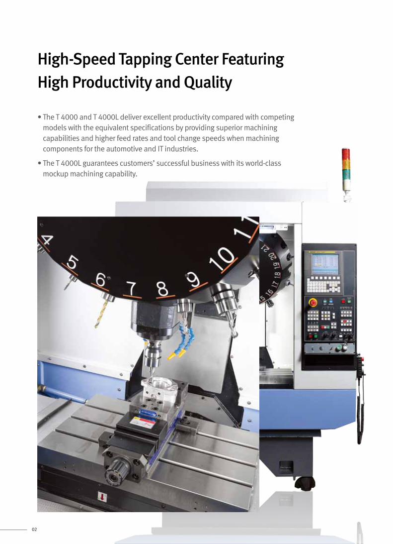
• The T 4000 and T 4000L deliver excellent productivity compared with competing models with the equivalent specifications by providing superior machining capabilities and higher feed rates and tool change speeds when machining components for the automotive and IT industries.
• The T 4000L guarantees customers’ successful business with its world-class mockup machining capability.
02
High-Speed Tapping Center Featuring High Productivity and Quality

The T 4000 and T 4000L deliver excellent productivity compared with competing models with the equivalent specifications by providing superior machining capabilities and higher feed rates and tool change speeds when machining components for the automotive and IT industries.
1
The T 4000 and T 4000L offer excellent user convenience thanks to their ergonomic design and ease of operation.
4
3
The T 4000 and T 4000L, which feature a servo motor-driven ATC, a spindle with an enhanced structure, and an FEM-based design, deliver excellent quality and reliability.
03
The T 4000 and T 4000L offer customers a wide range of machining capabilities including powerful cutting and mockup machining.
2
※ The image above shows a DOOSAN CNC D300 Controller.
Features
Excellent Productivity
Flexible Machining Capabilities
Reliability
Ease of Operation

04
Each axis is equipped with the most powerful AC servo motor in its class, thus enabling the most rapid traverse.
DOOSAN Fanuc i series / DOOSAN CNC D300 (Automotive and IT components)
X / Y / Z 56 / 56 / 56 m/min (2204.7 / 2204.7 / 2204.7 ipm)
Fanuc 31i (mockup processing)
X / Y / Z 48 / 48 / 48 m/min (1189.8 / 1189.8 / 1189.8 ipm)
Tool Change Time (C-T-C)
Reduced
Reduced
Reduced
Reduced
2.2 sec.Previous model
Previous model
Previous model
Previous model
18 %1.8 sec.T 4000 / T 4000L
Tool Change Time (T-T-T)
1.5 sec.
13 %1.3 sec.T 4000 / T 4000L
Acceleration 0 → 12000 r/min
1.376 sec.
21 %1.09 sec.T 4000 / T 4000L
Deceleration 12000 → 0 r/min
1.648 sec.
78 %T 4000 / T 4000L
Previous model
14T 4000 / T 4000L
21
Excellent Productivity
Fast Tool Change Cycle
ATC Tool Magazine
Spindle Acceleration / Deceleration
Rapid Traverse
Delivers faster tool change time than competitors’ products, contributing to greater productivity.
Tool Storage Capacity
std.
0.36 sec.0.36 sec.
05
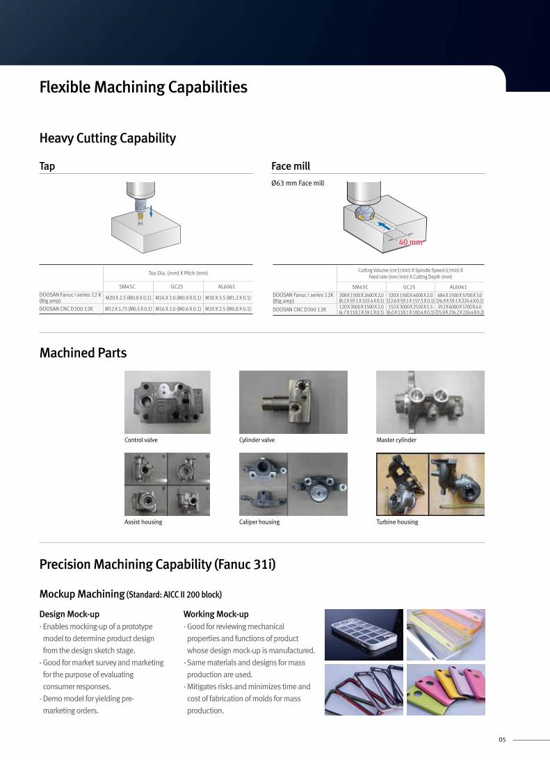
Heavy Cutting Capability
Precision Machining Capability (Fanuc 31i)
Mockup Machining (Standard: AICC II 200 block)
Design Mock-up- Enables mocking-up of a prototype
model to determine product design
from the design sketch stage.
- Good for market survey and marketing
for the purpose of evaluating
consumer responses.
- Demo model for yielding pre-
marketing orders.
Working Mock-up- Good for reviewing mechanical
properties and functions of product
whose design mock-up is manufactured.
- Same materials and designs for mass
production are used.
- Mitigates risks and minimizes time and
cost of fabrication of molds for mass
production.
Machined Parts
Control valve Cylinder valve Master cylinder
Assist housing Caliper housing Turbine housing
Tap
Too Dia. (mm) X Pitch (mm)
SM45C GC25 AL6061
DOOSAN Fanuc i series 12 K(Big amp) M20 X 2.5 (M0.8 X 0.1) M24 X 3.0 (M0.9 X 0.1) M30 X 3.5 (M1.2 X 0.1)
DOOSAN CNC D300 12K M12 X 1.75 (M0.5 X 0.1) M16 X 2.0 (M0.6 X 0.1) M20 X 2.5 (M0.8 X 0.1)
Cutting Volume (cm3/min) X Spindle Speed (r/min) X Feed rate (mm/min) X Cutting Depth (mm)
SM45C GC25 AL6061DOOSAN Fanuc i series 12K(Big amp)
208 X 1500 X 2600 X 2.0(8.2 X 59.1 X 102.4 X 0.1)
320 X 1500 X 4000 X 2.0(12.6 X 59.1 X 157.5 X 0.1)
684 X 1500 X 5700 X 3.0(26.9 X 59.1 X 224.4 X 0.1)
DOOSAN CNC D300 12K 120 X 3000 X 1500 X 2.0(4.7 X 118.1 X 59.1 X 0.1)
153 X 3000 X 2550 X 1.5(6.0 X 118.1 X 100.4 X 0.1)
912 X 6000 X 5700 X 4.0(35.9 X 236.2 X 224.4 X 0.2)
Face millØ63 mm Face mill
40 mm
Flexible Machining Capabilities

Reliability
06
Improved System Structure and Enhanced Rigidity through FEM Analysis
The dynamic rigidity of the system
has been enhanced by reducing
the head weight and modifying
the bed and ATC structures.
Structural modification has enhanced the dynamic rigidity of the ATC against vibration in the X / Z directions.
Dynamic rigidity in the X axis has been improved by improving the bed structure.
Sealed enclosure Equipped with servo motor
ATC• High durability and reliability due to servo motor.
• Excellent oil-resistance ensured by sealed enclosure
of the ATC drive unit.
Spindle• Lightweight, direct-coupled spindle reduces vibration
and noise.
• Two-side locking system extends lifecycle of tool and
delivers more powerful precision machining.
Equipped with a High-Reliability Unit
Dynamic rigidity in Y axis
Previo usPrevious model
T 4000 / T 4000L
126 %
Increase rate
49 %
Increase rate
Dynamic rigidity in X axis
Previous model
T 4000 / T 4000L
Taper contactFlange contact

07
Ease of Operation
Machine Convenience
Compact Size
Width Height Height to the work table
T 4000 1620 (63.8) 2380 (93.7) 799 (31.5)
T 4000L 2050 (80.7) 2380 (93.7) 799 (31.5)
Convenient Fanuc Control
Variable Control of Work-Piece LoadUsing an M-code corresponding to the workpiece weight automatically selects a table transfer pattern suitable for the work weight.
FANUC M-code M384 M380 M381
T 4000 Work Weight 0 ~ 130 kg 130 ~ 190 kg 190 ~ 300 kgT 4000L Work Weight 0 ~ 130 kg 130 ~ 190 kg 190 ~ 300 kg
AICC As the feed rate of the machine accelerates to achieve high-speed, high-precision cutting, geometry errors occur by acceleration and deceleration. This function reduces geometry errors in contour cutting by looking ahead blocks and controlling the servo motor.
DOOSAN Fanuc i series : AIAPC 20 Block AICC 40 Block AICCⅡ 200 Block
Fanuc 31i : AICCⅡ 200 Block AICCⅡ 600 Block AICCⅡ 1000 Block
Improved Position of Flood Coolant Nozzle
The coolant block is
positioned on the rear side
of the head body to enable
simultaneous movement
of the nozzle and tool,
enhancing the convenience
of machining setting.
The height of the machine has been
reduced compared to that of conventional models to allow
installation in apartment-type factories, while the height of the
work table has been reduced to improve user convenience.
OP Convenience
124
3
The operation panel provides an option for custom function switches for more convenient and better working condition.
The buttons have been partitioned to prevent mistakes when pressing buttons.
User-Friendly Operation PanelThe operation panel provides an option for custom function switches for more convenient and better working condition.
PCMCIA CardThe PCMCIA card enables the uploading and downloading of the NC program, NC parameters, tool information, and ladder programs, and also supports DNC operation.
USB PortThe USB memory stick enables the uploading and downloading of the NC program, NC parameters, and tool information. (DNC operation is not supported.)
Convenience Functions (Hot Keys)Frequently used functions can be accessed and used quickly and easily by clicking the hot key buttons:
Tapping Retract function: A function for releasing a seized tool by reverse rotating the spindle in the Manual mode when the tool is caught due to a power shutdown, emergency stop or NC reset during the machining process.
One-touch zero return function: Pressing the button in the Manual mode returns the z axis to the primary zero point.
ATC position return function: Pressing the ATC Position Return button in the Manual mode returns the z axis to the secondary zero point, allowing the tool magazine to rotate.
Tool Change function: In Manual mode, pressing the button automatically replaces the current tool with the next tool (current tool number + 1).
1 3
4
2
Height
Width
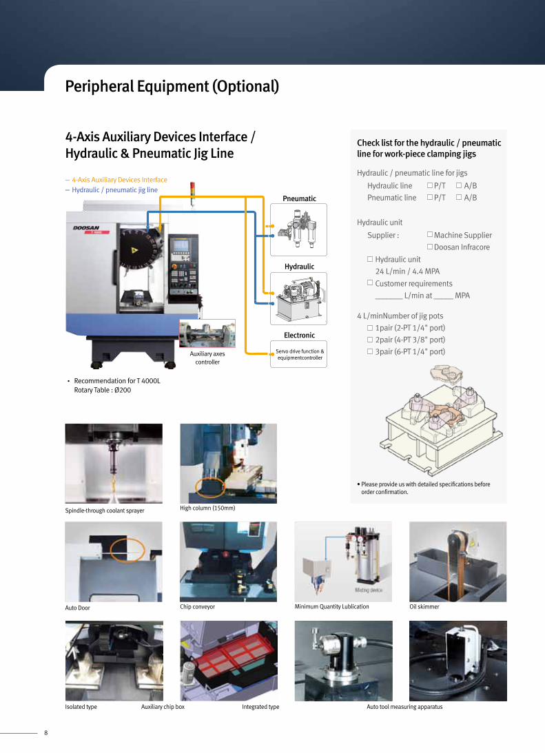
Peripheral Equipment (Optional)
Spindle-through coolant sprayer High column (150mm)
Integrated type Auto tool measuring apparatusIsolated type Auxiliary chip box
• Recommendation for T 4000L Rotary Table : Ø200
- 4-Axis Auxiliary Devices Interface- Hydraulic / pneumatic jig line
4-Axis Auxiliary Devices Interface / Hydraulic & Pneumatic Jig Line
Check list for the hydraulic / pneumatic line for work-piece clamping jigs
4 L/minNumber of jig pots
1pair (2-PT 1/4" port)
2pair (4-PT 3/8" port)
3pair (6-PT 1/4" port)
Hydraulic / pneumatic line for jigs
Hydraulic line P/T A/B
Pneumatic line P/T A/B
Hydraulic unit
Supplier : Machine Supplier
Doosan Infracore
Hydraulic unit
24 L/min / 4.4 MPA
Customer requirements
_______ L/min at _____ MPA
• Please provide us with detailed specifications before order confirmation.
Auto Door Minimum Quantity Lublication Oil skimmerChip conveyor
8
Auxiliary axes controller
Servo drive function & equipmentcontroller
Pneumatic
Electronic
Hydraulic

Spindle Power – Torque Curve
Max Spindle Speed 12000 r/min
DOOSAN Fanuc i series
Spindle Motor : 13 / 7.5 / 5.5 / 3.7 kW
3.5 (2.6)
0.4 N.m (0.3 ft-lbs)
7.0 (5.2)
0.6 N.m (0.4 ft-lbs)
11.8 (8.7)
0.9 (1.2 Hp)
0.0
1.5 (2.0 Hp)
0.0
Spindle speed (r/min)
Continuous
10min, S3 25%
5min
2.2kW(10min, S3 25%)
1.1kW (Cont.)
3.7kW (5min)
3,000 18,000 24,000
Torque : N·m (ft-lbs) Power : kW (Hp)
Torque : N·m (ft-lbs) Power : kW (Hp)
Torque : N·m (ft-lbs) Power : kW (Hp)
Torque : N·m (ft-lbs) Power : kW (Hp)
35.0 (25.8)
4.4 N.m (3.2 ft-lbs)
23.50 (17.3)
2.94 N.m (2.2 ft-lbs)
47.7 (35.2)
82.7 (61.0)
6.0 N.m (4.4 ft-lbs)8.8 N.m
3.7 (5.0 Hp)
0.0
7.5 (10.1 Hp)
11.0 (14.8 Hp)
5.5 (7.4 Hp)
Spindle speed (r/min)
Continuous
S3 25%7.5kW (S3 25%)
3.7kW (Cont.)
13kW (S3 15%)
5.5kW (30min, S3 60%)30min, S3 60%
S3 15%
1,500 10,000 12,000
35.0 (25.8)
4.4 N.m (3.2 ft-lbs)
23.50 (17.3)
2.94 N.m (2.2 ft-lbs)
47.7 (35.2)
6.0 N.m (4.4 ft-lbs)
70.0 (51.7)
7.2 N.m (5.3 ft-lbs)
3.7
0.0
7.5
9.0
5.5
Spindle speed (r/min)
Continuous
S3 25%
S3 15%
7.5kW (S3 25%)
5.5kW (30min, S3 60%)S3 60%
Continuous
S3 25%
S3 15%
3.7kW (Cont.)
11kW (S3 15%)
30min,
1,500 10,000 12,000
8.8 (6.5)
4.0 N.m (3.0 ft-lbs)
23.9 (17.6)
9.2 (12.3) 5.0 N.m (3.7 ft-lbs)
0.0
11.5 (15.4)
Spindle speed (r/min)
S1 : Continuous
Peak, 1min15kW (Peak, 1min)
5.5kW (S1 : Cont.)
6,000 10,000 12,000
Max Spindle Speed 12000 r/min
Fanuc 31i
Spindle Motor : 11 / 7.5 / 5.5 / 3.7 kW
3.5 (2.6)
0.4 N.m (0.3 ft-lbs)
7.0 (5.2)
0.6 N.m (0.4 ft-lbs)
11.8 (8.7)
0.9 (1.2 Hp)
0.0
1.5 (2.0 Hp)
0.0
Spindle speed (r/min)
Continuous
10min, S3 25%
5min
2.2kW(10min, S3 25%)
1.1kW (Cont.)
3.7kW (5min)
3,000 18,000 24,000
Torque : N·m (ft-lbs) Power : kW (Hp)
Torque : N·m (ft-lbs) Power : kW (Hp)
Torque : N·m (ft-lbs) Power : kW (Hp)
Torque : N·m (ft-lbs) Power : kW (Hp)
35.0 (25.8)
4.4 N.m (3.2 ft-lbs)
23.50 (17.3)
2.94 N.m (2.2 ft-lbs)
47.7 (35.2)
82.7 (61.0)
6.0 N.m (4.4 ft-lbs)8.8 N.m
3.7 (5.0 Hp)
0.0
7.5 (10.1 Hp)
11.0 (14.8 Hp)
5.5 (7.4 Hp)
Spindle speed (r/min)
Continuous
S3 25%7.5kW (S3 25%)
3.7kW (Cont.)
13kW (S3 15%)
5.5kW (30min, S3 60%)30min, S3 60%
S3 15%
1,500 10,000 12,000
35.0 (25.8)
4.4 N.m (3.2 ft-lbs)
23.50 (17.3)
2.94 N.m (2.2 ft-lbs)
47.7 (35.2)
6.0 N.m (4.4 ft-lbs)
70.0 (51.7)
7.2 N.m (5.3 ft-lbs)
3.7
0.0
7.5
9.0
5.5
Spindle speed (r/min)
Continuous
S3 25%
S3 15%
7.5kW (S3 25%)
5.5kW (30min, S3 60%)S3 60%
Continuous
S3 25%
S3 15%
3.7kW (Cont.)
11kW (S3 15%)
30min,
1,500 10,000 12,000
8.8 (6.5)
4.0 N.m (3.0 ft-lbs)
23.9 (17.6)
9.2 (12.3) 5.0 N.m (3.7 ft-lbs)
0.0
11.5 (15.4)
Spindle speed (r/min)
S1 : Continuous
Peak, 1min15kW (Peak, 1min)
5.5kW (S1 : Cont.)
6,000 10,000 12,000
Max Spindle Speed 24000 r/min
Fanuc 31i Doosan Fanuc i Series
Spindle Motor : 3.7 / 2.2 / 1.1 kW
3.5 (2.6)
0.4 N.m (0.3 ft-lbs)
7.0 (5.2)
0.6 N.m (0.4 ft-lbs)
11.8 (8.7)
0.9 (1.2 Hp)
0.0
1.5 (2.0 Hp)
0.0
Spindle speed (r/min)
Continuous
10min, S3 25%
5min
2.2kW(10min, S3 25%)
1.1kW (Cont.)
3.7kW (5min)
3,000 18,000 24,000
Torque : N·m (ft-lbs) Power : kW (Hp)
Torque : N·m (ft-lbs) Power : kW (Hp)
Torque : N·m (ft-lbs) Power : kW (Hp)
Torque : N·m (ft-lbs) Power : kW (Hp)
35.0 (25.8)
4.4 N.m (3.2 ft-lbs)
23.50 (17.3)
2.94 N.m (2.2 ft-lbs)
47.7 (35.2)
82.7 (61.0)
6.0 N.m (4.4 ft-lbs)8.8 N.m
3.7 (5.0 Hp)
0.0
7.5 (10.1 Hp)
11.0 (14.8 Hp)
5.5 (7.4 Hp)
Spindle speed (r/min)
Continuous
S3 25%7.5kW (S3 25%)
3.7kW (Cont.)
13kW (S3 15%)
5.5kW (30min, S3 60%)30min, S3 60%
S3 15%
1,500 10,000 12,000
35.0 (25.8)
4.4 N.m (3.2 ft-lbs)
23.50 (17.3)
2.94 N.m (2.2 ft-lbs)
47.7 (35.2)
6.0 N.m (4.4 ft-lbs)
70.0 (51.7)
7.2 N.m (5.3 ft-lbs)
3.7
0.0
7.5
9.0
5.5
Spindle speed (r/min)
Continuous
S3 25%
S3 15%
7.5kW (S3 25%)
5.5kW (30min, S3 60%)S3 60%
Continuous
S3 25%
S3 15%
3.7kW (Cont.)
11kW (S3 15%)
30min,
1,500 10,000 12,000
8.8 (6.5)
4.0 N.m (3.0 ft-lbs)
23.9 (17.6)
9.2 (12.3) 5.0 N.m (3.7 ft-lbs)
0.0
11.5 (15.4)
Spindle speed (r/min)
S1 : Continuous
Peak, 1min15kW (Peak, 1min)
5.5kW (S1 : Cont.)
6,000 10,000 12,000
Max Spindle Speed 12000 r/min
DOOSAN CNC D300
Spindle Motor : 15 / 5.5 kW
9
std.
std.
std.
opt. opt.
(17.4 / 10.1 / 7.4 / 5.0) Hp
(14.8 / 10.1 / 7.4 / 5.0) Hp (5.0 / 3.0 / 1.5) Hp
(20.1 / 7.4) Hp

10
1616 (63.6)1200 (47.2)210 (8.3) 206 (8.1)
810 (31.9)1620 (63.8)
620 (24.4)30 (1.2)
650 (25.6)260 (10.2)
320 (12.6) 980 (38.6) 320 (12.6)
260 (10.2)
548 (21.6) (DOOR OPEN)578 (22.8) 2524 (99.4)
2074 (81.7)1624 (63.9)78 (3.1)
450 (17.7)450 (17.7)
350
(13.
8)
221
(8.7
)39
1 (1
5.4)
1951
(76.
8)
150 (5.
9)
351 (13.8) 200 (7.9) 400 (15.7)
334 (13.1) 1205 (47.4)
650 (25.6)
325 (12.8) 325 (12.8)
Detail A
Detail B
22 (0.9)
1 (0.1) 12 (0.5)
14 H8
1 (0.1)
9 (0.4)
14 (0
.6)
14 H
8
24 (0
.9)
0.3 (0
.0)3.7
(0.1
)
100
(3.9
)10
0 (3
.9)
100
(3.9
)10
0 (3
.9)
200
(7.9
)20
0 (7
.9) 40
0 (1
5.7)
85 (3.3) 900 (35.4)2524 (99.4)
200 (7.9)
180
(7.1
)12
40 (4
8.8)
2009
(79.
1)21
89 (8
6.2)
(SH
IPPI
NG
HEI
GHT)
23
80 (9
3.7)
(W/O
TSC
MAX
)24
17 (9
5.2)
(WIT
H TS
C M
AX)
R 596 (23.5)10
0 (3.9
)
124
(4.9
)10
00 (3
9.4)
280 (
11.0)
493
(19.
4)75
1 (2
9.6)
1244
(49.
0)12
80 (5
0.4)
317 (
12.5)
352 (
13.9)
799
(31.
5)GR
OUN
D TO
TABL
E SU
RFAC
E
(X/2 STROKE) (X/2 STROKE)
(Y/2 STROKE) (Y/2 STROKE)
(Z S
TRO
KE)
100 (3
.9)
Top ViewUnit : mm (Inch)
Tool Specification
Table
48.4 (1.9)
Ø 1
2.5H
7
Ø 3
1.75 Ø 3
8
Ø 4
6H8
Ø 1
1
Ø 1
6.5
Ø 7
Ø 1
2H7
30˚
Ø 1
6.1H
12
16.3 (0.6) 16.3 (0.6)
13 (0.5)2.5 (0.1) 2.5 (0.1)
23 (0.9)
5 (0.2) 4 (0.2)
20 (0.8)
3 (0.1)30˚ 30˚
45˚
24 (0.9)
M12×P1.75
M12×P1.75
MAS405-P30T-1(45˚)
Taper 7 / 24
7 (0.3)
13.6 (0.5)
17 (0.7)
2 (0.1) 20 (0.8)
0.1
D1≦ � 40mm (1.6 Inch)L1≦240mm (9.4 Inch)
D2≦ � 80mm (3.1 Inch)L2≦160mm (6.3 Inch)D3≦ � 52mm (2.0 Inch)L3≦ � 34mm (1.3 Inch)
L1L2
D2
D1
L3
D3
0.2
Front View Side View
T 4000 Machine External Dimensions

1025 (40.4)
1244
(49.
0)75
1 (2
9.6)
493
(19.
4)28
0 (11
.0)10
00 (3
9.4)
1280
(50.
4)12
4 (4
.9)
100
(3.9
)1200 (47.2)1616 (63.6)
208 (8.2)208 (8.2)
2050 (80.7)
100
(3.9
)10
0 (3
.9)
100
(3.9
)10
0 (3
.9)
200
(7.9
)20
0 (7
.9)
400
(15.
7)R 596 (23.5)
793 (31.2) 2524 (99.4)2074 (71.7)
1624 (63.9)
1205 (47.4)2524 (99.4)
334 (13.1)
351 (13.8) 400 (15.7) 200 (7.9)200 (7.9)
1951
(76.
8)39
1 (1
5.4)
221 (
8.7)
85 (3.3) 900 (35.4)
450 (17.7)78450 (17.7)
835 (32.9) 422 (16.6)31 (1.2)
180
(7.1
)12
40 (4
8.8)
2009
(79.
1)21
89 (8
6.2)
(SH
IPPI
NG
HEI
GHT)
2380
(93.
7) (W
/O TS
C M
AX)
2417
(95
.2) (
WIT
H TS
C M
AX)
799
(31.
5)GR
OUN
D TO
TABL
E SU
RFAC
E
350 (
13.8
)150
(5.9)
Z ST
ROKE
Y/2 STROKE Y/2 STROKE
(X/2 STROKE)350 (13.5)350 (13.5)(X/2 STROKE)
317 (
12.5)
352 (
13.9)
100 (
3.9)
762 (30) (DOOR OPEN)
850 (33.5)
980 (38.6)2050 (80.7)
535 (21.1)535 (21.1)
850 (33.5)
425 (16.7) 425 (16.7)
Detail A
Detail B
22 (0.9)
12 (0.5)
14 H8
1 (0.0)
1 (0.0)
9 (0.4)
14 (0
.6)
14 H
8
24 (0
.9)
0.3 (0
.0)3.7
(0.1)
T 4000 L Machine External Dimensions
11
Unit : mm (Inch)
48.4 (1.9)
Ø 1
2.5H
7
Ø 3
1.75 Ø 3
8
Ø 4
6H8
Ø 1
1
Ø 1
6.5
Ø 7
Ø 1
2H7
30˚
Ø 1
6.1H
12
16.3 (0.6) 16.3 (0.6)
13 (0.5)2.5 (0.1) 2.5 (0.1)
23 (0.9)
5 (0.2) 4 (0.2)
20 (0.8)
3 (0.1)30˚ 30˚
45˚
24 (0.9)
M12×P1.75
M12×P1.75
MAS405-P30T-1(45˚)
Taper 7 / 24
7 (0.3)
13.6 (0.5)
17 (0.7)
2 (0.1) 20 (0.8)
0.1
D1≦ � 40mm (1.6 Inch)L1≦240mm (9.4 Inch)
D2≦ � 80mm (3.1 Inch)L2≦160mm (6.3 Inch)D3≦ � 52mm (2.0 Inch)L3≦ � 34mm (1.3 Inch)
L1L2
D2
D1
L3
D3
0.2
Top View
Tool Specification
Table
Front View Side View

Machine Specification
Description Unit T 4000 T 4000L
DOOSAN Fanuc i series DOOSAN Fanuc i series Fanuc 31i
Travel
Travel distance
X-axis mm (inch) 520 (20.5) 700 (27.6)
Y-axis mm (inch) 400 (15.7)
Z-axis mm (inch) 350 (13.8)
Distance from spindle nose to table top mm (inch) 150 ~ 500 (5.9 ~ 19.7)
Distance from spindle nose to column mm (inch) 443 (17.4)
FeedrateRapid traverse rate
X - axis m/min (ipm) 56 (2204.7) 56 (2204.7) 48 (1889.7)
Y - axis m/min (ipm) 56 (2204.7) 56 (2204.7) 48 (1889.7)
Z - axis m/min (ipm) 56 (2204.7) 56 (2204.7) 48 (1889.7)
Cutting feedrate m/min (ipm) 28 (1102.3) 28 (1102.3) 24 (944.8)
Table
Table size mm (inch) 650 X 400 (25.6 X 15.7) 850 X 400 (33.5 X 15.7)
Table loading capacity kg (lb) 300 (661.4)
Table type T-SLOT (3-100 X 14H8)
Spindle
Max. spindle speed r/min 12000 {24000} 12000 24000 {12000}
Spindle taper ISO #30, 7/24 TAPER
Max. spindle torque N·m (ft-lbs)82.7 (S3 15%) {11.8 (5 min)}(61.0 ((S3 15%) {8.7 (5min)})
82.7 (S3 15%)(61.0 (S3 15%))
11.8 (5 min) {70 (S3 15%)}(8.7 (5 min) {51.7 (S3 15%)})
Automatic tool changer
Type of tool shank MAS403 BT 30 / MAS403 P30T-1 45deg
Tool storage capacity ea 21
Max tool diameterW / adjacent tool mm (inch) 80 (3.1)
W / O adjacent tool mm (inch) 150 (5.9)
Max. tool length mm (inch) 240 (tool diameter ≦ 40) (9.4 (tool diameter ≦ 1.6))
Max. tool weight kg (lb) 2.8 (6.2)
Max. magazine weight kg (lb) 33 (72.8)
Max. magazine eccentric load weight kg (lb) 21 (46.3)
Tool selection FIXED ADDRESS
Tool change time (tool-to-tool) s 1.3 1.3
Tool change time (chip-to-chip) s 1.8 1.8
MotorSpindle motor power kW
13 (S3 15%) / 7.5 (S3 25%) / 5.5 (30 min) / 3.7 (Cont.) / {3.7 (5 min) / 2.2 (10 min) / 1.1 (Cont.)}
(17.4 (S3 15%) / 10.1 (S3 25%) / 7.4 (30 min) / 5.0 (Cont.) / {5.0 (5 min) / 3.0 (10 min) / 1.5 (Cont.)} )
13 (S3 15%) / 7.5 (S3 25%) / 5.5 (30min.) / 3.7 (Cont.)
(17.4 (S3 15%) / 10.1 (S3 25%) / 7.4 (30min.) / 5.0 (Cont.))
3.7 (5 min) / 2.2 (10 min) / 1.1 (Cont.){11 (S3 15%) / 7.5 (S3 25%) / 5.5 (30 min) / 3.7 (Cont.)}
(5.9 (5 min) / 3.0 (10 min) / 1.5 (Cont.){14.8 (S3 15%) / 10.1 (S3 25%) / 7.4 (30 min) / 5.0 (Cont.)})
Coolant pump motor power kW FLOOD : 0.4 BASE COOLANT : 0.9 (FLOOD : 0.5 BASE COOLANT : 1.2)
Power source
Electric power supply kVA 19 {15.7} 19 17.5 {20.8}
Compressed air supply Mpa 0.54
Machine size
Height mm (inch) 2380 (93.7)
Length mm (inch) 2602 (102.4)
Width mm (inch) 1620 (63.8) 2050 (80.7)
Weight kg (lb) 2400 (94.5) 2500 (98.4)
Standard Features• Base coolant system
• Components for installation
(Leveling Bolt & Block)
• Splash guard (full-closed cover)
• Lubrication system
• Work light
• System condition indicator lamp
• Coolant system
• Coolant tank and chip pan
• Standard work tools
• Portable MPG
• Top Cover
{ } : option* Applied with G 100 function
Optional Features• Rotary table for 4 axes
• Spindle-through coolant
sprayer
• Shower coolant
• Oil skimmer
• Coolant gun
• Rear-type chip conveyor & bucket
• Auto Door
• High column (150 mm block)
• Hydraulic system
• Minimum Quantity Lubrication
* Please consult with technical engineer if the density of coolant is higher than 10cp, as this could affect the filtration function
12

NC Unit Specifications
Operation, Setting & Display, etc- Alarm history display - Automatic corner override G62 - Coordinate rotation G68, G69- Cycle start / Feed hold - Dry run - Graphic display - Loadmeter display - Memory card interface - MDI / DISPLAY unit 8.4" Color LCD- Operation functions (Tape / Memory / MDI / Manual
operation)- Optional angle chamfering / corner R - Polar coordinate command G15 / G16- Programmable mirror image G50.1 / G51.1- PCMCIA port front of panel - Program restart - Run hour and part number display - Scaling G50, G51- Single direction positioning G60- Single block - Stored stroke check 2 - USB Interface (Only Data Read & Write)
Optional specifications- AICC I (AI Contour Control I) 40 block preview- AICC II (AI Contour Control II) 200 block preview- Additional controlled axes 5 axes (4-axes simultaneous
control))- Fast Data Server
Control axis- Controlled axes 3 (X, Y, Z)- Simultaneous
controlled axesPositioning (G00) / Linear interpolation (G01): 3 axes
Arc interpolation (G02, G03): 2 axes- Backlash compensation - Least command increment 0.001mm / 0.0001"- Machine lock all axes / Z axis- Mirror image - Pitch error offset compensation each axis- Stored stroke check 1- Stored pitch error compensation
Interpolation & feed functions- 2nd reference point return G30- Cylindrical interpolation G07.1- Exact stop check G09, G61 (mode)- Helical interpolation - Jog override : 10% increments 0-200%- Rapid traverse override F0 (fine feed), 25 / 50 / 100- Reference point return G27, G28, G29- Skip function G31
DOOSAN Fanuc i series
Spindle & M-code functions- M-code function M3 digits- Spindle speed override : 10% increments 10-150%- Spindle orientation
Tool functions- Number of tool offsets 400ea- Tool length compensation G43, G44, G49- Tool position offset G45-G48- Tool life management
Programming & editing function- Absolute / Incremental programming G90 / G91- Auto. Coordinate system setting - Background editing - Canned cycle G73, G74, G76, G80 - G89, G99- Circular interpolation by radius programming - Custom macro - Inch / metric conversion G20 / G21- Label skip - Local / Machine coordinate system G52 / G53
- No. of Registered programs 400 ea- Optional block skip- Part program storage 1280m (512kB)- Playback - Rigid tapping G84, G74- Thread cutting - Work coordinate system G54 - G59
Spindle & M-code functions- M- code function M 3 digits
- Rigid tapping G84, G74
- Spindle orientation
- Spindle speed command S5 digits
- Spindle speed override 10 - 150%
- Spindle output switching
Interpolation & feed functions- 2nd reference point return G30- AICC II 200 block preview- Automatic corner deceleration- Automatic acceleration / deceleration - Exact stop check G09, G61(mode)- Feedrate override :10% increments 0 - 200%- Helical interpolation - Jog override :10% increments 0 - 200%- Linear ACC / DEC before interpolation(Specify AI Contour control II)- Linear ACC / DEC after interpolation- Manual handle feedrate 0.1/0.01/0.001mm- Override cancel M48 / M49- Rapid traverse override
F0 (fine feed), 25 / 50 / 100%- Rapid traverse bell-shaped acceleration / deceleration- Reference point return G27, G28- Skip function G31- Smooth backlash compensation- Thread cutting, synchronous cutting
Control axis- Controlled axes 3 (X, Y, Z)- Simultaneously controllable axes
Positioning (G00) / Linear interpolation (G01): 3 axesArc interpolation (G02, G03): 2 axes
- Backlash compensation - Least command increment 0.001mm / 0.0001"- Least input increment 0.001mm / 0.0001"- Machine lock all axes / Z axis - Mirror image Reverse axis movement
(setting screen and M - function)- Stored pitch error compensation
Pitch error offset compensation for each axis- Stored stroke check 1
Overtravel controlled by software- Position Switch
Programming & editing function- Absolute / Incremental programming G90 / G91- Additional work coordinate system (48 Pairs) G54.1 P1 - 48 pairs- Auto. Coordinate system setting - Background editing - Canned cycle G73, G74, G76, G80 - G89, G99- Coordinate system rotation G68, G69- Circular interpolation by radius programming- Custom macro - Extended part program editing - Inch / metric conversion G20 / G21- Label skip- Local / Machine coordinate system G52 / G53- Maximum commandable value
±99999.999mm (±9999.9999 inch)- No. of Registered programs 500 ea- Optional block skip
Tool functions- Number of tool offsets 64 ea- Tool nose radius compensation G40, G41, G42- Tool length compensation G43, G44, G49- Tool number command T3 digits- Tool life management - Tool offset memory C
H/D Code, Geometry / Wear memory- Tool length measurement
Optional specifications- 3-dimensional coordinate conversion
- 3-dimensional tool compensation- 3rd / 4th reference return
- Addition of tool pairs for tool life management 1024 pairs
- Additional controlled axes max. 12 axes per 1path- Additional work coordinate system G54.1 P1 - 300 (300 pairs)- AICC II 400 block preview - AICC II with High speed processing 600 block
- AICC II with Lock-ahead blocks expansion 1000 block
- Automatic corner override G62- Chopping function / Cylindrical interpolation G81.1 / G07.1
- Dynamic graphic display (This can’t use with the EZ Guide-i)
Machining profile drawing- EZ Guide i (Doosan infracore Conversational Programming Solution)
- Fast Data Server
- Figure copying G72.1, G72.2
- High speed skip function
- Interpolation type pitch error compensation
- Increment system 1/10
- Involute interpolation G02.2, G03.2
- Manual handle feed 2/3 unit
- Machining time stamp function
- No. of Registered programs 1000 / 4000ea
- Number of tool offsets 99 / 200 / 400 / 499 / 999 / 2000 ea
- Optional block skip addition 2~9 blocks
- Part program storage 512KB / 1MB / 2MB / 4MB / 8MB
- Playback function
- Polar coordinate command G15 / G16
- Polar coordinate interpolation G12.1 / G13.1
- Programmable mirror image G50.1 / G51.1
- Scaling G50, G51
- Single direction positioning G60
- Tape format for FS15
- Tool load monitoring function (doosan)
Operation, Setting & Display, etc- Alarm display - Alarm history display- Clock function- Cycle start / Feed hold - Display of PMC alarm message
Message display when PMC alarm occurred- Dry run- Ethernet function - External data input- Graphic display Tool path drawing- Handle interruption- Help function- Loadmeter display- MDI / DISPLAY unit
10.4" color LCD, Keyboard for data input, soft-keys- Memory card interface - Multi language display - Operation functions Tape / Memory / MDI / Manual- Operation history display- Program restart- Run hour and part number display- Search function Sequence NO. / Program NO.- Self - diagnostic function - Servo setting screen - Single block - Stored stroke check 2 / 3 - USB Interface (Only Data Read & Write)
Fanuc 31i
- Optional stop M01- Part program storage 640m (256kB)- Program number O4-digits- Program stop / end M00 / M02, M30- Programmable data input
Tool offset and work offset are entered by G10, G11- Sub program Up to 10 nesting- Tape code ISO / EIA Automatic discrimination- Work coordinate system G54 - G59
13
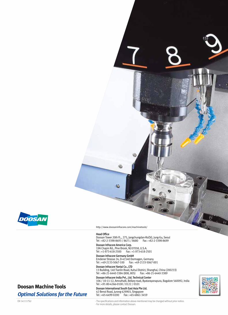
Head Office Doosan Tower 20th FL., 275, Jangchungdan-Ro(St), Jung-Gu, Seoul Tel : +82-2-3398-8693 / 8671 / 8680 Fax : +82-2-3398-8699
Doosan Infracore America Corp. 19A Chapin Rd., Pine Brook, NJ 07058, U.S.A. Tel : +1-973-618-2500 Fax : +1-973-618-2501
Doosan Infracore Germany GmbH Emdener Strasse 24, D-41540 Dormagen, Germany Tel : +49-2133-5067-100 Fax : +49-2133-5067-001
Doosan Infracore Yantai Co., LTD 13 Building, 140 Tianlin Road, Xuhui District, Shanghai, China (200233) Tel : +86-21-6440-3384 (808, 805) Fax : +86-21-6440-3389
Doosan Infracore India Pvt., Ltd. Technical Center 106 / 10-11-12, Amruthalli, Bellary road, Byatarayanapura, Bagalore 560092, India Tel : +91-80-4266-0100 / 0122 / 0101
Doosan International South East Asia Pte Ltd. 42 Benoi Road, Jurong 629903, Singapore Tel : +65-6499-0200 Fax : +65-6861-3459
- The specifications and information above-mentioned may be changed without prior notice.- For more details, please contact Doosan.
EN 141117SU
http://www.doosaninfracore.com/machinetools/