high pressure/low volume centrifugal fiberglass blower
TRANSCRIPT

PRVSHIGH PRESSURE/LOW VOLUME
CENTRIFUGAL FIBERGLASS BLOWER
PRVS INTRODUCTION AND FEATURES HIGH PRESSURE/LOW VOLUME
CENTRIFUGAL FIBERGLASS BLOWER
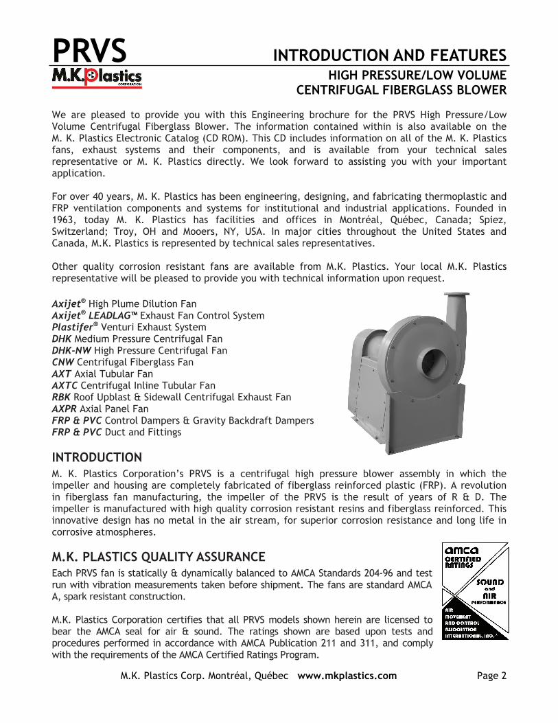
We are pleased to provide you with this Engineering brochure for the PRVS High Pressure/Low Volume Centrifugal Fiberglass Blower. The information contained within is also available on the M. K. Plastics Electronic Catalog (CD ROM). This CD includes information on all of the M. K. Plastics fans, exhaust systems and their components, and is available from your technical sales representative or M. K. Plastics directly. We look forward to assisting you with your important application. For over 40 years, M. K. Plastics has been engineering, designing, and fabricating thermoplastic and FRP ventilation components and systems for institutional and industrial applications. Founded in 1963, today M. K. Plastics has facilities and offices in Montréal, Québec, Canada; Spiez, Switzerland; Troy, OH and Mooers, NY, USA. In major cities throughout the United States and Canada, M.K. Plastics is represented by technical sales representatives. Other quality corrosion resistant fans are available from M.K. Plastics. Your local M.K. Plastics representative will be pleased to provide you with technical information upon request.
Axijet® High Plume Dilution Fan Axijet® LEADLAG™ Exhaust Fan Control System Plastifer® Venturi Exhaust System DHK Medium Pressure Centrifugal Fan DHK-NW High Pressure Centrifugal Fan CNW Centrifugal Fiberglass Fan AXT Axial Tubular Fan AXTC Centrifugal Inline Tubular Fan RBK Roof Upblast & Sidewall Centrifugal Exhaust Fan AXPR Axial Panel Fan FRP & PVC Control Dampers & Gravity Backdraft Dampers FRP & PVC Duct and Fittings
INTRODUCTION M. K. Plastics Corporation’s PRVS is a centrifugal high pressure blower assembly in which the impeller and housing are completely fabricated of fiberglass reinforced plastic (FRP). A revolution in fiberglass fan manufacturing, the impeller of the PRVS is the result of years of R & D. The impeller is manufactured with high quality corrosion resistant resins and fiberglass reinforced. This innovative design has no metal in the air stream, for superior corrosion resistance and long life in corrosive atmospheres. M.K. PLASTICS QUALITY ASSURANCE Each PRVS fan is statically & dynamically balanced to AMCA Standards 204-96 and test run with vibration measurements taken before shipment. The fans are standard AMCA A, spark resistant construction. M.K. Plastics Corporation certifies that all PRVS models shown herein are licensed to bear the AMCA seal for air & sound. The ratings shown are based upon tests and procedures performed in accordance with AMCA Publication 211 and 311, and comply with the requirements of the AMCA Certified Ratings Program.
M.K. Plastics Corp. Montréal, Québec www.mkplastics.com Page 2
PRVS DESIGN AND CONSTRUCTION HIGH PRESSURE/LOW VOLUME
CENTRIFUGAL FIBERGLASS BLOWER
M.K. Plastics Corp. Montréal, Québec www.mkplastics.com Page 3
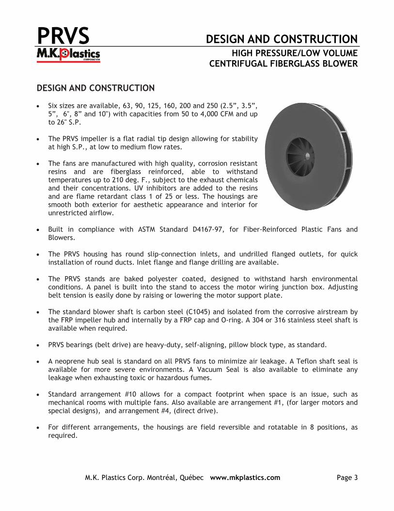
DESIGN AND CONSTRUCTION Six sizes are available, 63, 90, 125, 160, 200 and 250 (2.5”, 3.5”,
5”, 6", 8” and 10") with capacities from 50 to 4,000 CFM and up to 26" S.P.
The PRVS impeller is a flat radial tip design allowing for stability
at high S.P., at low to medium flow rates. The fans are manufactured with high quality, corrosion resistant
resins and are fiberglass reinforced, able to withstand temperatures up to 210 deg. F., subject to the exhaust chemicals and their concentrations. UV inhibitors are added to the resins and are flame retardant class 1 of 25 or less. The housings are smooth both exterior for aesthetic appearance and interior for unrestricted airflow.
Built in compliance with ASTM Standard D4167-97, for Fiber-Reinforced Plastic Fans and
Blowers. The PRVS housing has round slip-connection inlets, and undrilled flanged outlets, for quick
installation of round ducts. Inlet flange and flange drilling are available. The PRVS stands are baked polyester coated, designed to withstand harsh environmental
conditions. A panel is built into the stand to access the motor wiring junction box. Adjusting belt tension is easily done by raising or lowering the motor support plate.
The standard blower shaft is carbon steel (C1045) and isolated from the corrosive airstream by
the FRP impeller hub and internally by a FRP cap and O-ring. A 304 or 316 stainless steel shaft is available when required.
PRVS bearings (belt drive) are heavy-duty, self-aligning, pillow block type, as standard. A neoprene hub seal is standard on all PRVS fans to minimize air leakage. A Teflon shaft seal is
available for more severe environments. A Vacuum Seal is also available to eliminate any leakage when exhausting toxic or hazardous fumes.
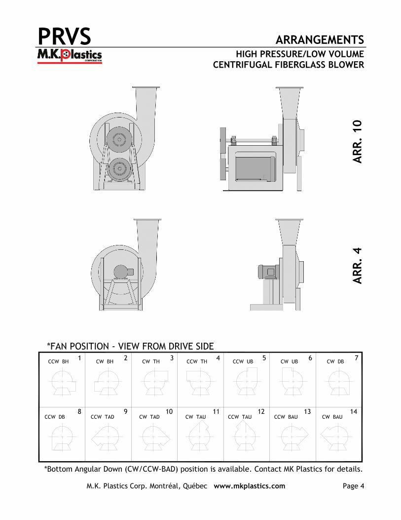
Standard arrangement #10 allows for a compact footprint when space is an issue, such as
mechanical rooms with multiple fans. Also available are arrangement #1, (for larger motors and special designs), and arrangement #4, (direct drive).
For different arrangements, the housings are field reversible and rotatable in 8 positions, as
required.
PRVS ARRANGEMENTS HIGH PRESSURE/LOW VOLUME
CENTRIFUGAL FIBERGLASS BLOWER
M.K. Plastics Corp. Montréal, Québec www.mkplastics.com Page 4
AR
R.
10
AR
R.
4
PRVS PRVS 63 PERFORMANCE HIGH PRESSURE/LOW VOLUME
CENTRIFUGAL FIBERGLASS BLOWER
M.K. Plastics Corp. Montréal, Québec www.mkplastics.com Page 5
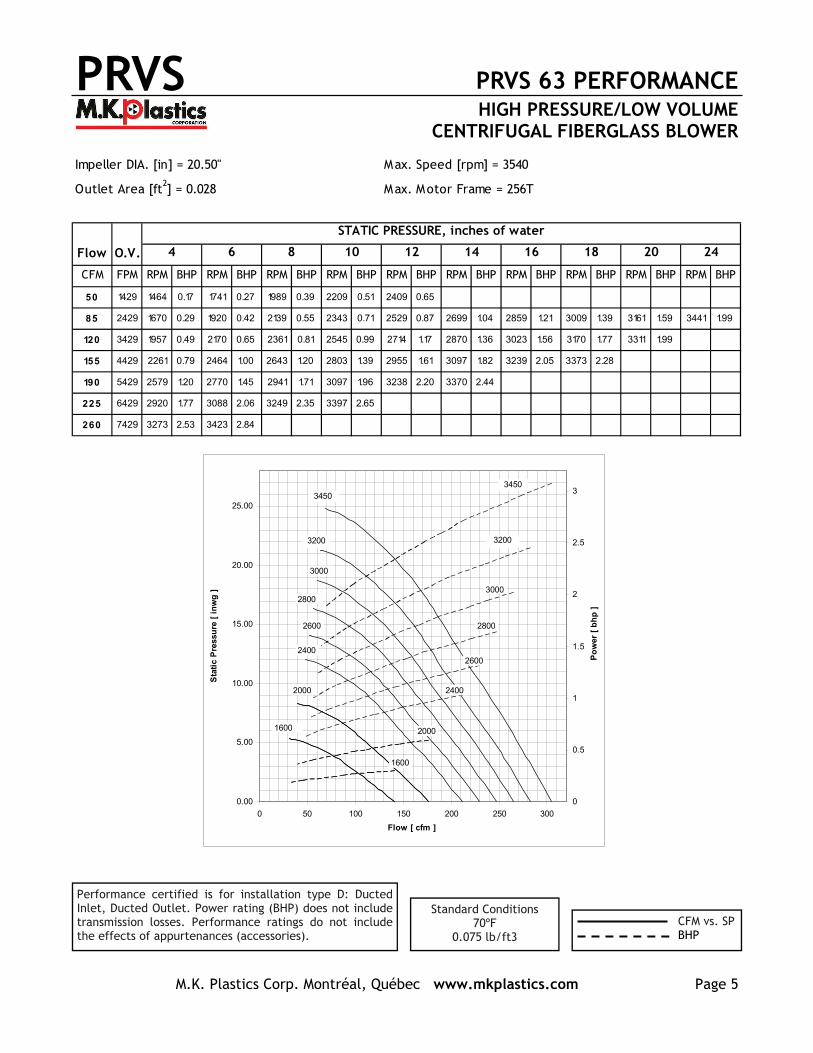
Impeller DIA. [in] = 20.50" Max. Speed [rpm] = 3540
Outlet Area [ft2] = 0.028 Max. Motor Frame = 256T
Flow O.V.
CFM FPM RPM BHP RPM BHP RPM BHP RPM BHP RPM BHP RPM BHP RPM BHP RPM BHP RPM BHP RPM BHP
50 1429 1464 0.17 1741 0.27 1989 0.39 2209 0.51 2409 0.65
85 2429 1670 0.29 1920 0.42 2139 0.55 2343 0.71 2529 0.87 2699 1.04 2859 1.21 3009 1.39 3161 1.59 3441 1.99
120 3429 1957 0.49 2170 0.65 2361 0.81 2545 0.99 2714 1.17 2870 1.36 3023 1.56 3170 1.77 3311 1.99
155 4429 2261 0.79 2464 1.00 2643 1.20 2803 1.39 2955 1.61 3097 1.82 3239 2.05 3373 2.28
190 5429 2579 1.20 2770 1.45 2941 1.71 3097 1.96 3238 2.20 3370 2.44
225 6429 2920 1.77 3088 2.06 3249 2.35 3397 2.65
260 7429 3273 2.53 3423 2.84
STATIC PRESSURE, inches of water
4 6 8 10 12 14 16 18 20 24
0.00
5.00
10.00
15.00
20.00
25.00
0 50 100 150 200 250 300
Flow [ cfm ]
Sta
tic
Pre
ssu
re [
in
wg
]
0
0.5
1
1.5
2
2.5
3
Po
wer
[ b
hp
]
1600
2600
2800
3000
2800
3000
2000
2400
1600
2000
2400
2600
3200
3450
3200
3450
Performance certified is for installation type D: Ducted Inlet, Ducted Outlet. Power rating (BHP) does not include transmission losses. Performance ratings do not include the effects of appurtenances (accessories).
Standard Conditions 70ºF
0.075 lb/ft3 CFM vs. SP BHP

PRVS PRVS 90 PERFORMANCE HIGH PRESSURE/LOW VOLUME
CENTRIFUGAL FIBERGLASS BLOWER
M.K. Plastics Corp. Montréal, Québec www.mkplastics.com Page 6
Performance certified is for installation type D: Ducted Inlet, Ducted Outlet. Power rating (BHP) does not include transmission losses. Performance ratings do not include the effects of appurtenances (accessories).
Standard Conditions 70ºF
0.075 lb/ft3 CFM vs. SP BHP
Impeller DIA. [in] = 20.50" Max. Speed [rpm] = 3540
Outlet Area [ft2] = 0.054 Max. Motor Frame = 256T
Flow O.V.
CFM FPM RPM BHP RPM BHP RPM BHP RPM BHP RPM BHP RPM BHP RPM BHP RPM BHP RPM BHP RPM BHP
100 1754 1420 0.21 1693 0.33 1935 0.47 2151 0.62 2347 0.77 2527 0.93 2695 1.09 2853 1.27 3003 1.44
150 2632 1588 0.35 1817 0.49 2029 0.64 2226 0.81 2407 0.98 2583 1.18 2749 1.38 2903 1.60 3051 1.82 3393 2.37
200 3509 1799 0.55 2007 0.72 2199 0.90 2370 1.09 2529 1.29 2689 1.50 2841 1.71 2983 1.94 3117 2.16
250 4386 2032 0.83 2226 1.04 2401 1.26 2559 1.47 2711 1.70 2855 1.94 2989 2.18 3114 2.42 3241 2.67
300 5263 2279 1.21 2459 1.46 2620 1.72 2773 1.97 2911 2.22 3045 2.49 3176 2.76 3299 3.04 3417 3.32
350 6140 2535 1.70 2703 2.00 2857 2.30 2997 2.60 3132 2.89 3259 3.19 3379 3.49
400 7018 2797 2.32 2955 2.67 3101 3.01 3235 3.35 3361 3.70
18 20 25
STATIC PRESSURE, inches of water
4 6 8 10 12 14 16
0.00
5.00
10.00
15.00
20.00
25.00
30.00
0 100 200 300 400 500 600
Flow [ cfm ]
Sta
tic
Pre
ssu
re [
in
wg
]
0
0.5
1
1.5
2
2.5
3
3.5
4
4.5
5
Po
wer
[ b
hp
]
1600
2600
2800
3000
2800
3000
2000
2400
1600
2000
2400
2600
3200
3450
3200
3450
PRVS PRVS 125 PERFORMANCE HIGH PRESSURE/LOW VOLUME
CENTRIFUGAL FIBERGLASS BLOWER
M.K. Plastics Corp. Montréal, Québec www.mkplastics.com Page 7
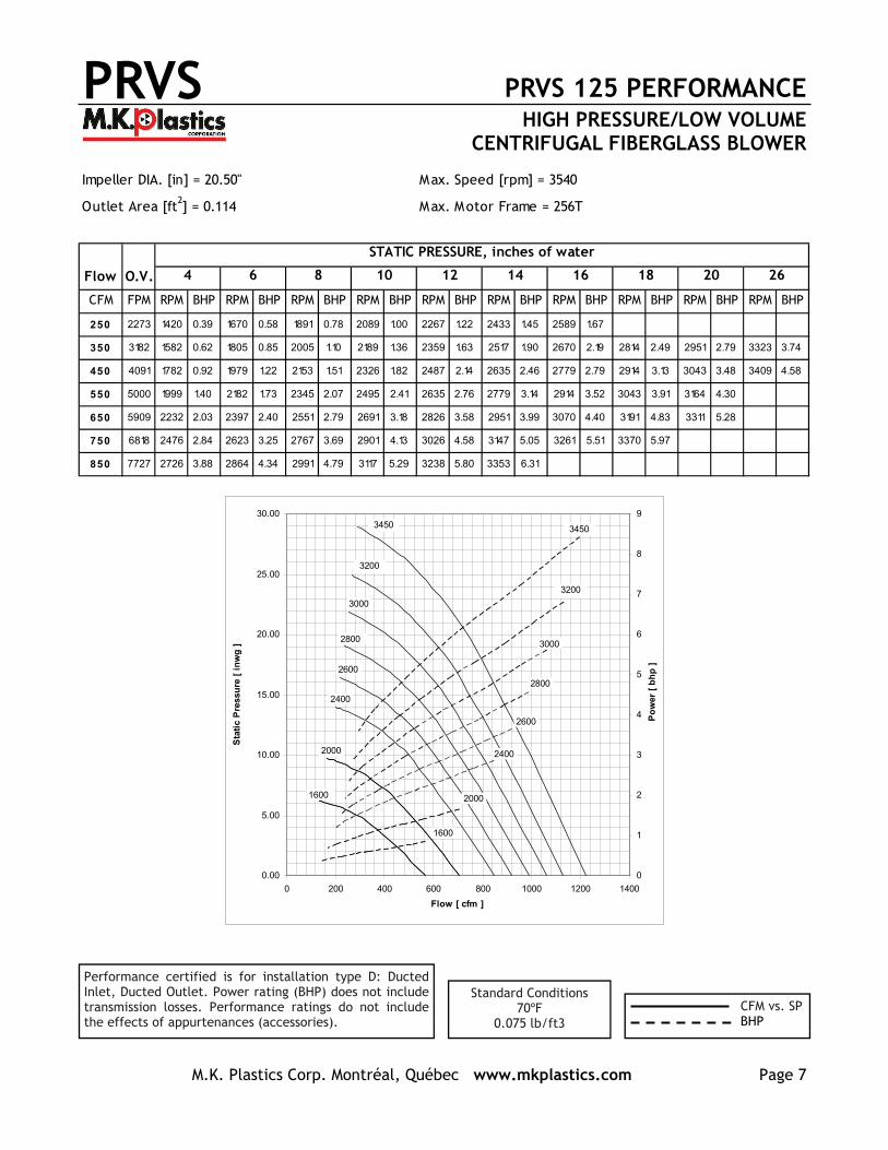
Performance certified is for installation type D: Ducted Inlet, Ducted Outlet. Power rating (BHP) does not include transmission losses. Performance ratings do not include the effects of appurtenances (accessories).
Standard Conditions 70ºF
0.075 lb/ft3 CFM vs. SP BHP
Impeller DIA. [in] = 20.50" Max. Speed [rpm] = 3540
Outlet Area [ft2] = 0.114 Max. Motor Frame = 256T
Flow O.V.
CFM FPM RPM BHP RPM BHP RPM BHP RPM BHP RPM BHP RPM BHP RPM BHP RPM BHP RPM BHP RPM BHP
250 2273 1420 0.39 1670 0.58 1891 0.78 2089 1.00 2267 1.22 2433 1.45 2589 1.67
350 3182 1582 0.62 1805 0.85 2005 1.10 2189 1.36 2359 1.63 2517 1.90 2670 2.19 2814 2.49 2951 2.79 3323 3.74
450 4091 1782 0.92 1979 1.22 2153 1.51 2326 1.82 2487 2.14 2635 2.46 2779 2.79 2914 3.13 3043 3.48 3409 4.58
550 5000 1999 1.40 2182 1.73 2345 2.07 2495 2.41 2635 2.76 2779 3.14 2914 3.52 3043 3.91 3164 4.30
650 5909 2232 2.03 2397 2.40 2551 2.79 2691 3.18 2826 3.58 2951 3.99 3070 4.40 3191 4.83 3311 5.28
750 6818 2476 2.84 2623 3.25 2767 3.69 2901 4.13 3026 4.58 3147 5.05 3261 5.51 3370 5.97
850 7727 2726 3.88 2864 4.34 2991 4.79 3117 5.29 3238 5.80 3353 6.31
26
STATIC PRESSURE, inches of water
4 6 8 10 12 14 16 18 20
0.00
5.00
10.00
15.00
20.00
25.00
30.00
0 200 400 600 800 1000 1200 1400
Flow [ cfm ]
Sta
tic
Pre
ssu
re [
in
wg
]
0
1
2
3
4
5
6
7
8
9
Po
wer
[ b
hp
]
1600
2600
2800
3000
2800
3000
2000
2400
1600
2000
2400
2600
3200
3450
3200
3450
PRVS PRVS 160 PERFORMANCE HIGH PRESSURE/LOW VOLUME
CENTRIFUGAL FIBERGLASS BLOWER
M.K. Plastics Corp. Montréal, Québec www.mkplastics.com Page 8
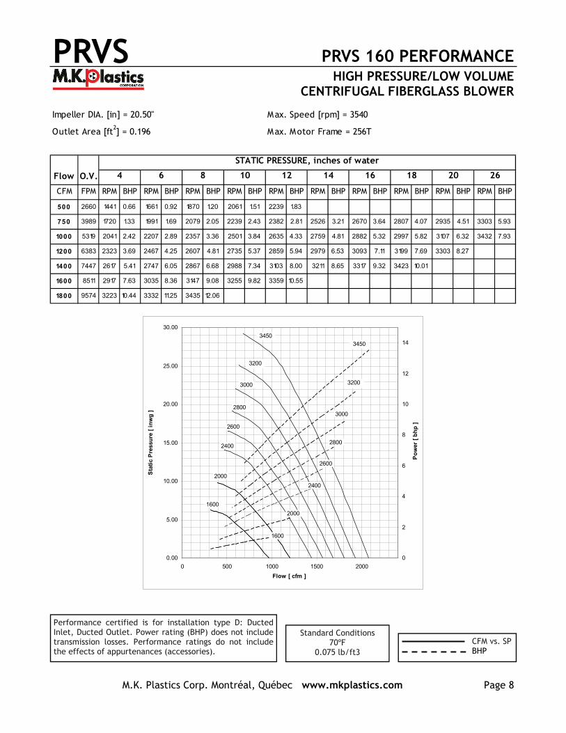
Performance certified is for installation type D: Ducted Inlet, Ducted Outlet. Power rating (BHP) does not include transmission losses. Performance ratings do not include the effects of appurtenances (accessories).
Standard Conditions 70ºF
0.075 lb/ft3 CFM vs. SP BHP
Impeller DIA. [in] = 20.50" Max. Speed [rpm] = 3540
Outlet Area [ft2] = 0.196 Max. Motor Frame = 256T
Flow O.V.
CFM FPM RPM BHP RPM BHP RPM BHP RPM BHP RPM BHP RPM BHP RPM BHP RPM BHP RPM BHP RPM BHP
500 2660 1441 0.66 1661 0.92 1870 1.20 2061 1.51 2239 1.83
750 3989 1720 1.33 1991 1.69 2079 2.05 2239 2.43 2382 2.81 2526 3.21 2670 3.64 2807 4.07 2935 4.51 3303 5.93
1000 5319 2041 2.42 2207 2.89 2357 3.36 2501 3.84 2635 4.33 2759 4.81 2882 5.32 2997 5.82 3107 6.32 3432 7.93
1200 6383 2323 3.69 2467 4.25 2607 4.81 2735 5.37 2859 5.94 2979 6.53 3093 7.11 3199 7.69 3303 8.27
1400 7447 2617 5.41 2747 6.05 2867 6.68 2988 7.34 3103 8.00 3211 8.65 3317 9.32 3423 10.01
1600 8511 2917 7.63 3035 8.36 3147 9.08 3255 9.82 3359 10.55
1800 9574 3223 10.44 3332 11.25 3435 12.06
26
STATIC PRESSURE, inches of water
4 6 8 10 12 14 16 18 20
0.00
5.00
10.00
15.00
20.00
25.00
30.00
0 500 1000 1500 2000
Flow [ cfm ]
Sta
tic
Pre
ssu
re [
in
wg
]
0
2
4
6
8
10
12
14
Po
wer
[ b
hp
]
1600
2600
2800
3000
2800
3000
2000
2400
1600
2000
2400
2600
3200
3450
3200
3450

PRVS PRVS 200 PERFORMANCE HIGH PRESSURE/LOW VOLUME
CENTRIFUGAL FIBERGLASS BLOWER
M.K. Plastics Corp. Montréal, Québec www.mkplastics.com Page 9
Performance certified is for installation type D: Ducted Inlet, Ducted Outlet. Power rating (BHP) does not include transmission losses. Performance ratings do not include the effects of appurtenances (accessories).
Standard Conditions 70ºF
0.075 lb/ft3 CFM vs. SP BHP
Impeller DIA. [in] = 20.50" Max. Speed [rpm] = 3540
Outlet Area [ft2] = 0.307 Max. Motor Frame = 256T
Flow O.V.
CFM FPM RPM BHP RPM BHP RPM BHP RPM BHP RPM BHP RPM BHP RPM BHP RPM BHP RPM BHP RPM BHP
1000 3257 1623 1.54 1835 2.03 2029 2.55 2209 3.12 2373 3.70 2523 4.29 2664 4.89 2805 5.53 2939 6.18 3305 8.18
1300 4235 1861 2.56 2044 3.15 2214 3.76 2376 4.41 2523 5.05 2673 5.79 2811 6.52 2943 7.27 3067 8.03 2411 10.36
1600 5212 2123 4.04 2288 4.77 2438 5.49 2579 6.21 2714 6.95 2849 7.75 2976 8.56 3095 9.35 3217 10.24
1900 6189 2400 6.06 2547 6.92 2685 7.78 2817 8.65 2938 9.49 3057 10.35 3170 11.21 3285 12.14 3399 13.12
2100 6840 2591 7.77 2729 8.72 2857 9.66 2982 10.61 3101 11.57 3211 12.50 3320 13.45 3426 14.41
2400 7818 2882 10.92 3009 12.02 3129 13.11 3238 14.15 3351 15.26
2700 8795 3185 14.93 3297 16.13 3407 17.36
STATIC PRESSURE, inches of water
4 6 8 10 12 14 16 18 20 26
0.00
5.00
10.00
15.00
20.00
25.00
30.00
0 500 1000 1500 2000 2500 3000 3500
Flow [ cfm ]
Sta
tic
Pre
ssu
re [
in
wg
]
0
5
10
15
20
Po
wer
[ b
hp
]
1600
2600
2800
3000
2800
3000
2000
2400
1600
2000
2400
2600
3200
3450
3200
3450

PRVS PRVS 250 PERFORMANCE HIGH PRESSURE/LOW VOLUME
CENTRIFUGAL FIBERGLASS BLOWER
M.K. Plastics Corp. Montréal, Québec www.mkplastics.com Page 10
Performance certified is for installation type D: Ducted Inlet, Ducted Outlet. Power rating (BHP) does not include transmission losses. Performance ratings do not include the effects of appurtenances (accessories).
Standard Conditions 70ºF
0.075 lb/ft3 CFM vs. SP BHP
Impeller DIA. [in] = 20.50" Max. Speed [rpm] = 3540
Outlet Area [ft2] = 0.479 Max. Motor Frame = 256T
Flow O.V.
CFM FPM RPM BHP RPM BHP RPM BHP RPM BHP RPM BHP RPM BHP RPM BHP RPM BHP RPM BHP RPM BHP
1500 3132 1682 2.34 1895 3.06 2085 3.76 2255 4.45 2420 5.20 2570 5.96 2714 6.74 2857 7.61 2993 8.50 3364 11.25
2000 4175 1964 4.10 2147 5.03 2320 5.98 2476 6.93 2626 7.88 2764 8.79 2897 9.73 3020 10.64 3145 11.65
2500 5219 2276 6.73 2435 7.87 2585 9.01 2726 10.18 2864 11.36 2997 12.58 3120 13.77 3238 14.94 3353 16.10
3000 6263 2609 10.47 2747 11.79 2876 13.11 3009 14.53 3132 15.92 3249 17.31 3367 18.76
3400 7098 2882 14.36 3011 15.89 3132 17.40 3244 18.88 3361 20.46
3750 7829 3132 18.60 3244 20.19 3361 21.91
4000 8351 3311 22.11 3414 23.76
STATIC PRESSURE, inches of water
4 6 8 10 12 14 16 18 20 26
0.00
5.00
10.00
15.00
20.00
25.00
30.00
0 500 1000 1500 2000 2500 3000 3500 4000 4500 5000
Flow [ cfm ]
Sta
tic
Pre
ssu
re [
in
wg
]
0
5
10
15
20
25
30
Po
wer
[ b
hp
]
1600
2600
2800
3000
2800
3000
2000
2400
1600
2000
2400
2600
3200
3450
3200
3450
PRVS SOUND PERFORMANCE HIGH PRESSURE/LOW VOLUME
CENTRIFUGAL FIBERGLASS BLOWER
M.K. Plastics Corp. Montréal, Québec www.mkplastics.com Page 11
PRVS 63Sp LwA
RPM inwg 63 125 250 500 1000 2000 4000 8000 dB1600 0.25 96 91 97 88 78 70 62 55 91
1.50 96 89 98 89 78 70 62 54 912.25 95 89 98 89 78 71 64 56 91
2000 0.25 104 97 98 99 85 78 70 62 972.25 105 94 97 99 85 78 70 62 97
3.50 104 95 98 100 85 78 71 63 982400 0.25 111 102 99 107 91 84 76 68 104
3.50 113 99 97 108 91 84 76 68 1055.00 112 99 98 108 91 84 77 69 105
2600 0.25 113 104 101 110 94 86 78 70 1074.00 115 102 98 111 94 86 78 70 108
6.00 114 102 99 111 95 86 80 72 1082800 0.25 114 107 103 111 97 89 81 73 108
4.50 117 105 100 112 97 89 81 73 1097.00 115 105 101 112 98 89 82 74 109
3000 0.25 115 109 104 112 100 91 83 75 1105.00 118 108 102 113 101 91 83 75 110
8.00 117 108 103 113 101 91 84 77 1113200 0.25 116 112 106 113 103 93 85 77 111
6.00 119 111 103 113 104 93 85 77 1119.00 118 110 104 113 104 93 86 79 111
3450 0.25 118 114 108 113 107 95 88 80 1127.00 120 114 105 113 107 95 88 80 112
11.00 119 113 106 113 108 96 89 81 113
Frequency[Hz]PRVS 90
Sp LwA
RPM inwg 63 125 250 500 1000 2000 4000 8000 dB1600 0.25 92 88 95 85 74 69 62 55 88
2.50 93 86 94 83 73 67 60 53 874.50 91 85 92 81 72 66 59 52 85
2000 0.25 98 94 96 95 81 75 70 63 944.50 99 93 93 94 79 74 67 60 92
6.50 98 91 92 93 78 74 66 59 912400 0.25 103 99 97 104 87 81 76 69 101
6.50 104 98 93 103 84 80 73 66 1019.00 104 97 92 102 83 80 72 65 99
2600 0.25 105 101 98 107 90 83 78 71 1047.50 106 101 94 106 87 83 76 69 103
12.00 106 99 94 104 85 82 75 67 1012800 0.25 106 103 100 108 93 85 80 74 105
8.50 108 103 97 108 91 85 78 71 10514.00 108 101 96 105 89 84 77 70 103
3000 0.25 107 105 102 109 97 87 82 76 1079.50 109 106 99 109 95 87 80 73 106
16.00 109 104 98 107 93 86 79 72 1043200 0.25 108 107 103 110 100 89 84 78 108
11.00 110 107 101 109 98 88 82 75 10718.00 110 106 100 107 96 87 81 74 105
3450 0.25 110 109 105 110 103 92 86 80 10913.00 111 110 103 109 102 90 85 78 107
21.00 111 108 102 107 100 89 84 76 106
Frequency[Hz]
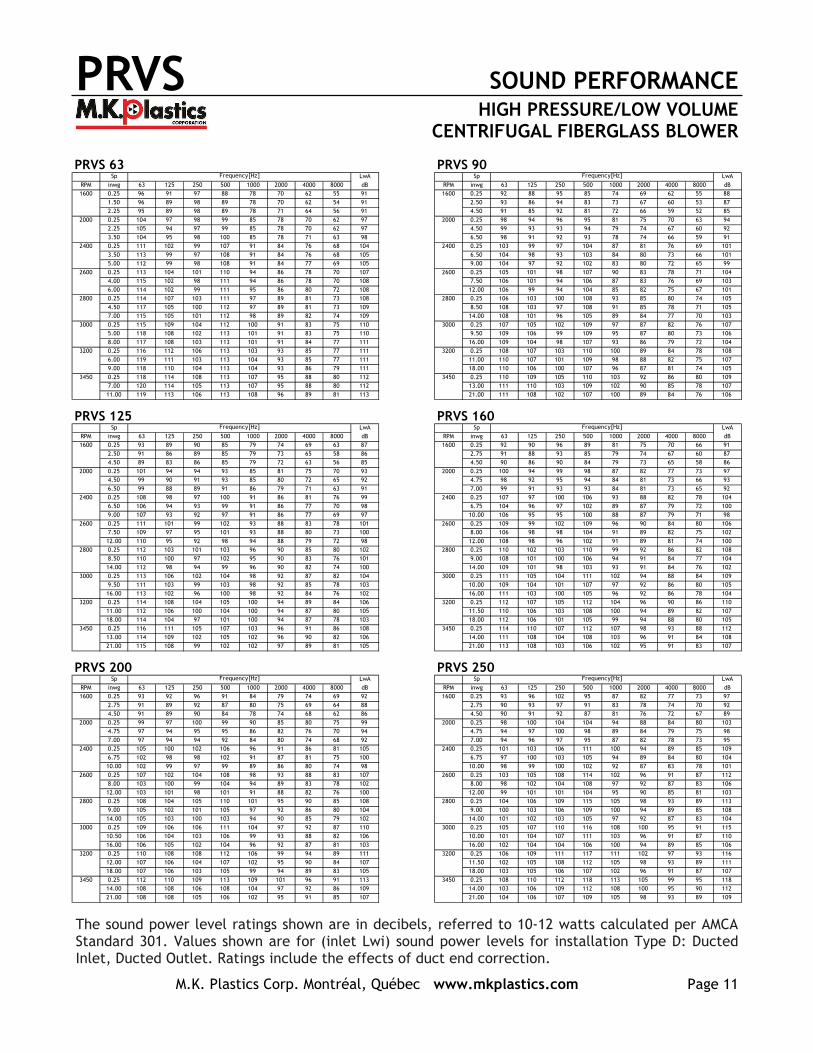
PRVS 125Sp LwA
RPM inwg 63 125 250 500 1000 2000 4000 8000 dB1600 0.25 93 89 90 85 79 74 69 63 87
2.50 91 86 89 85 79 73 65 58 864.50 89 83 86 85 79 72 63 56 85
2000 0.25 101 94 94 93 85 81 75 70 934.50 99 90 91 93 85 80 72 65 92
6.50 99 88 89 91 86 79 71 63 912400 0.25 108 98 97 100 91 86 81 76 99
6.50 106 94 93 99 91 86 77 70 989.00 107 93 92 97 91 86 77 69 97
2600 0.25 111 101 99 102 93 88 83 78 1017.50 109 97 95 101 93 88 80 73 100
12.00 110 95 92 98 94 88 79 72 982800 0.25 112 103 101 103 96 90 85 80 102
8.50 110 100 97 102 95 90 83 76 10114.00 112 98 94 99 96 90 82 74 100
3000 0.25 113 106 102 104 98 92 87 82 1049.50 111 103 99 103 98 92 85 78 103
16.00 113 102 96 100 98 92 84 76 1023200 0.25 114 108 104 105 100 94 89 84 106
11.00 112 106 100 104 100 94 87 80 10518.00 114 104 97 101 100 94 87 78 103
3450 0.25 116 111 105 107 103 96 91 86 10813.00 114 109 102 105 102 96 90 82 106
21.00 115 108 99 102 102 97 89 81 105
Frequency[Hz]PRVS 160
Sp LwA
RPM inwg 63 125 250 500 1000 2000 4000 8000 dB1600 0.25 92 90 96 89 81 75 70 66 91
2.75 91 88 93 85 79 74 67 60 874.50 90 86 90 84 79 73 65 58 86
2000 0.25 100 94 99 98 87 82 77 73 974.75 98 92 95 94 84 81 73 66 93
7.00 99 91 93 93 84 81 73 65 922400 0.25 107 97 100 106 93 88 82 78 104
6.75 104 96 97 102 89 87 79 72 10010.00 106 95 95 100 88 87 79 71 98
2600 0.25 109 99 102 109 96 90 84 80 1068.00 106 98 98 104 91 89 82 75 102
12.00 108 98 96 102 91 89 81 74 1002800 0.25 110 102 103 110 99 92 86 82 108
9.00 108 101 100 106 94 91 84 77 10414.00 109 101 98 103 93 91 84 76 102
3000 0.25 111 105 104 111 102 94 88 84 10910.00 109 104 101 107 97 92 86 80 105
16.00 111 103 100 105 96 92 86 78 1043200 0.25 112 107 105 112 104 96 90 86 110
11.50 110 106 103 108 100 94 89 82 10718.00 112 106 101 105 99 94 88 80 105
3450 0.25 114 110 107 112 107 98 93 88 11214.00 111 108 104 108 103 96 91 84 108
21.00 113 108 103 106 102 95 91 83 107
Frequency[Hz]
PRVS 200Sp LwA
RPM inwg 63 125 250 500 1000 2000 4000 8000 dB1600 0.25 93 92 96 91 84 79 74 69 92
2.75 91 89 92 87 80 75 69 64 884.50 91 89 90 84 78 74 68 62 86
2000 0.25 99 97 100 99 90 85 80 75 994.75 97 94 95 95 86 82 76 70 94
7.00 97 94 94 92 84 80 74 68 922400 0.25 105 100 102 106 96 91 86 81 105
6.75 102 98 98 102 91 87 81 75 10010.00 102 99 97 99 89 86 80 74 98
2600 0.25 107 102 104 108 98 93 88 83 1078.00 103 100 99 104 94 89 83 78 102
12.00 103 101 98 101 91 88 82 76 1002800 0.25 108 104 105 110 101 95 90 85 108
9.00 105 102 101 105 97 92 86 80 10414.00 105 103 100 103 94 90 85 79 102
3000 0.25 109 106 106 111 104 97 92 87 11010.50 106 104 103 106 99 93 88 82 106
16.00 106 105 102 104 96 92 87 81 1033200 0.25 110 108 108 112 106 99 94 89 111
12.00 107 106 104 107 102 95 90 84 10718.00 107 106 103 105 99 94 89 83 105
3450 0.25 112 110 109 113 109 101 96 91 11314.00 108 108 106 108 104 97 92 86 109
21.00 108 108 105 106 102 95 91 85 107
Frequency[Hz]PRVS 250
Sp LwA
RPM inwg 63 125 250 500 1000 2000 4000 8000 dB1600 0.25 93 96 102 95 87 82 77 73 97
2.75 90 93 97 91 83 78 74 70 924.50 90 91 92 87 81 76 72 67 89
2000 0.25 98 100 104 104 94 88 84 80 1034.75 94 97 100 98 89 84 79 75 98
7.00 94 96 97 95 87 82 78 73 952400 0.25 101 103 106 111 100 94 89 85 109
6.75 97 100 103 105 94 89 84 80 10410.00 98 99 100 102 92 87 83 78 101
2600 0.25 103 105 108 114 102 96 91 87 1128.00 98 102 104 108 97 92 87 83 106
12.00 99 101 101 104 95 90 85 81 1032800 0.25 104 106 109 115 105 98 93 89 113
9.00 100 103 106 109 100 94 89 85 10814.00 101 102 103 105 97 92 87 83 104
3000 0.25 105 107 110 116 108 100 95 91 11510.00 101 104 107 111 103 96 91 87 110
16.00 102 104 104 106 100 94 89 85 1063200 0.25 106 109 111 117 111 102 97 93 116
11.50 102 105 108 112 105 98 93 89 11118.00 103 105 106 107 102 96 91 87 107
3450 0.25 108 110 112 118 113 105 99 95 11814.00 103 106 109 112 108 100 95 90 112
21.00 104 106 107 109 105 98 93 89 109
Frequency[Hz]
The sound power level ratings shown are in decibels, referred to 10-12 watts calculated per AMCA Standard 301. Values shown are for (inlet Lwi) sound power levels for installation Type D: Ducted Inlet, Ducted Outlet. Ratings include the effects of duct end correction.
PRVS DIMENSIONS HIGH PRESSURE/LOW VOLUME
CENTRIFUGAL FIBERGLASS BLOWER
M.K. Plastics Corp. Montréal, Québec www.mkplastics.com Page 12
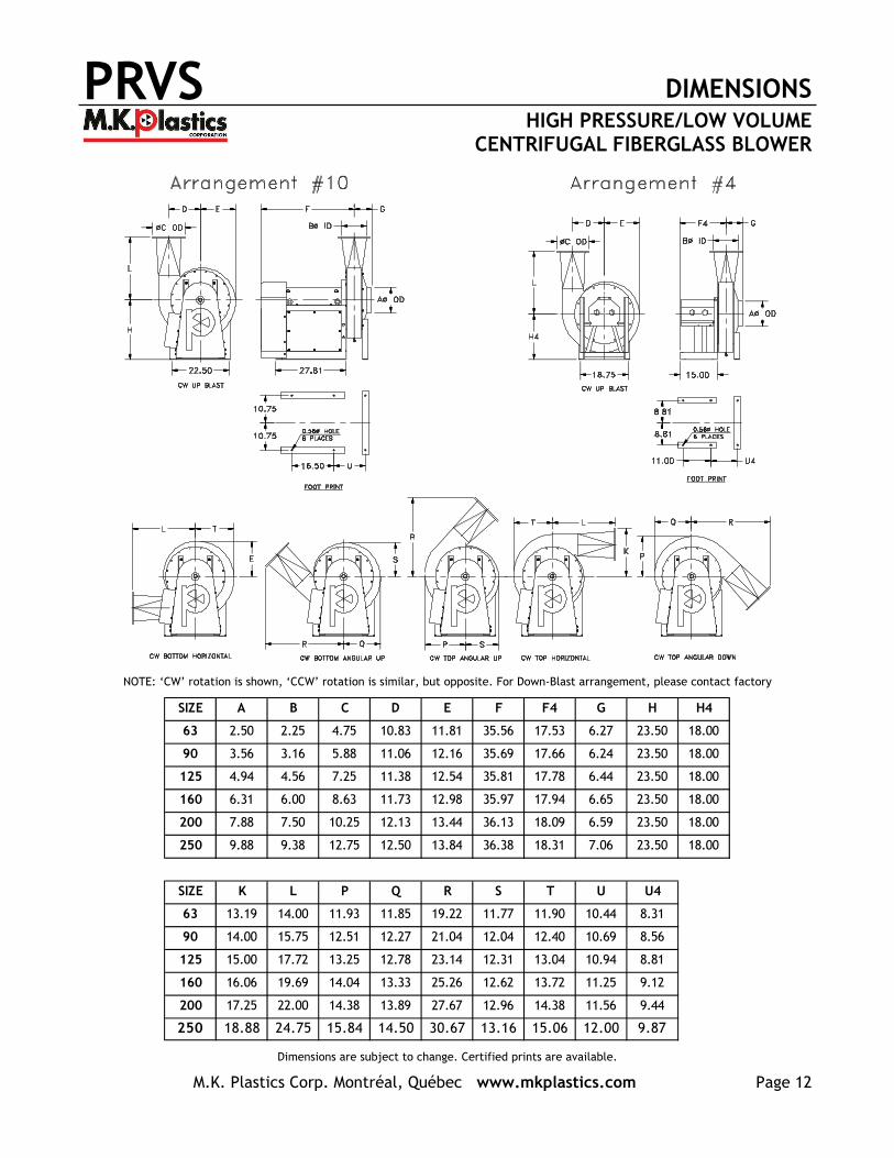
SIZE A B C D E F F4 G H H4
63 2.50 2.25 4.75 10.83 11.81 35.56 17.53 6.27 23.50 18.00
90 3.56 3.16 5.88 11.06 12.16 35.69 17.66 6.24 23.50 18.00
125 4.94 4.56 7.25 11.38 12.54 35.81 17.78 6.44 23.50 18.00
160 6.31 6.00 8.63 11.73 12.98 35.97 17.94 6.65 23.50 18.00
200 7.88 7.50 10.25 12.13 13.44 36.13 18.09 6.59 23.50 18.00
250 9.88 9.38 12.75 12.50 13.84 36.38 18.31 7.06 23.50 18.00
SIZE K L P Q R S T U U4
63 13.19 14.00 11.93 11.85 19.22 11.77 11.90 10.44 8.31
90 14.00 15.75 12.51 12.27 21.04 12.04 12.40 10.69 8.56
125 15.00 17.72 13.25 12.78 23.14 12.31 13.04 10.94 8.81
160 16.06 19.69 14.04 13.33 25.26 12.62 13.72 11.25 9.12
200 17.25 22.00 14.38 13.89 27.67 12.96 14.38 11.56 9.44
250 18.88 24.75 15.84 14.50 30.67 13.16 15.06 12.00 9.87
NOTE: ‘CW’ rotation is shown, ‘CCW’ rotation is similar, but opposite. For Down-Blast arrangement, please contact factory
Dimensions are subject to change. Certified prints are available.
PRVS CORROSION RESISTANCE GUIDE HIGH PRESSURE/LOW VOLUME
CENTRIFUGAL FIBERGLASS BLOWER
M.K. Plastics Corp. Montréal, Québec www.mkplastics.com Page 13
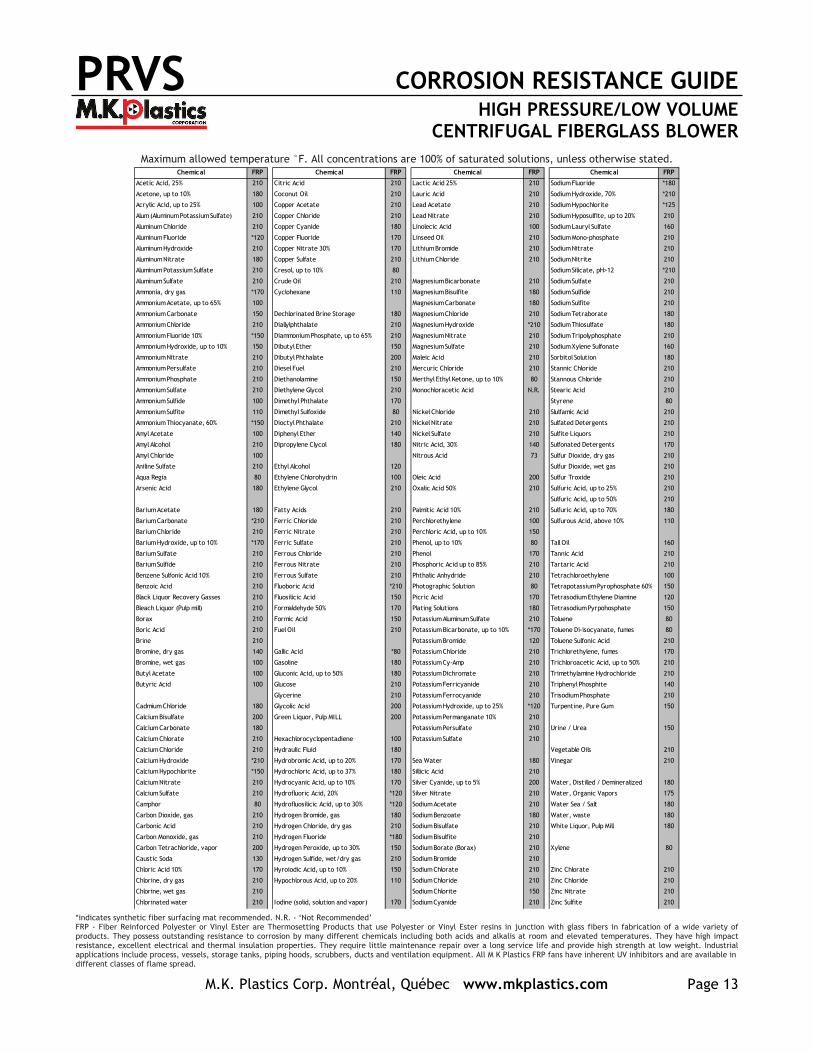
Maximum allowed temperature °F. All concentrations are 100% of saturated solutions, unless otherwise stated.
*indicates synthetic fiber surfacing mat recommended. N.R. - ‘Not Recommended’ FRP - Fiber Reinforced Polyester or Vinyl Ester are Thermosetting Products that use Polyester or Vinyl Ester resins in junction with glass fibers in fabrication of a wide variety of products. They possess outstanding resistance to corrosion by many different chemicals including both acids and alkalis at room and elevated temperatures. They have high impact resistance, excellent electrical and thermal insulation properties. They require little maintenance repair over a long service life and provide high strength at low weight. Industrial applications include process, vessels, storage tanks, piping hoods, scrubbers, ducts and ventilation equipment. All M K Plastics FRP fans have inherent UV inhibitors and are available in different classes of flame spread.
FRP FRP FRP FRP
Acetic Acid, 25% 210 Citric Acid 210 Lactic Acid 25% 210 Sodium Fluoride *180
Acetone, up to 10% 180 Coconut Oil 210 Lauric Acid 210 Sodium Hydroxide, 70% *210
Acrylic Acid, up to 25% 100 Copper Acetate 210 Lead Acetate 210 Sodium Hypochlorite *125
Alum (Aluminum Potassium Sulfate) 210 Copper Chloride 210 Lead Nitrate 210 Sodium Hyposulfite, up to 20% 210
Aluminum Chloride 210 Copper Cyanide 180 Linolecic Acid 100 Sodium Lauryl Sulfate 160
Aluminum Fluoride *120 Copper Fluoride 170 Linseed Oil 210 Sodium Mono-phosphate 210
Aluminum Hydroxide 210 Copper Nitrate 30% 170 Lithium Bromide 210 Sodium Nitrate 210
Aluminum Nitrate 180 Copper Sulfate 210 Lithium Chloride 210 Sodium Nitrite 210
Aluminum Potassium Sulfate 210 Cresol, up to 10% 80 Sodium Silicate, pH>12 *210
Aluminum Sulfate 210 Crude Oil 210 Magnesium Bicarbonate 210 Sodium Sulfate 210
Ammonia, dry gas *170 Cyclohexane 110 Magnesium Bisulfite 180 Sodium Sulfide 210
Ammonium Acetate, up to 65% 100 Magnesium Carbonate 180 Sodium Sulfite 210
Ammonium Carbonate 150 Dechlorinated Brine Storage 180 Magnesium Chloride 210 Sodium Tetraborate 180
Ammonium Chloride 210 Diallylphthalate 210 Magnesium Hydroxide *210 Sodium Thiosulfate 180
Ammonium Fluoride 10% *150 Diammonium Phosphate, up to 65% 210 Magnesium Nitrate 210 Sodium Tripolyphosphate 210
Ammonium Hydroxide, up to 10% 150 Dibutyl Ether 150 Magnesium Sulfate 210 Sodium Xylene Sulfonate 160
Ammonium Nitrate 210 Dibutyl Phthalate 200 Maleic Acid 210 Sorbitol Solution 180
Ammonium Persulfate 210 Diesel Fuel 210 Mercuric Chloride 210 Stannic Chloride 210
Ammonium Phosphate 210 Diethanolamine 150 Merthyl Ethyl Ketone, up to 10% 80 Stannous Chloride 210
Ammonium Sulfate 210 Diethylene Glycol 210 Monochloracetic Acid N.R. Stearic Acid 210
Ammonium Sulfide 100 Dimethyl Phthalate 170 Styrene 80
Ammonium Sulfite 110 Dimethyl Sulfoxide 80 Nickel Chloride 210 Slulfamic Acid 210
Ammonium Thiocyanate, 60% *150 Dioctyl Phthalate 210 Nickel Nitrate 210 Sulfated Detergents 210
Amyl Acetate 100 Diphenyl Ether 140 Nickel Sulfate 210 Sulfite Liquors 210
Amyl Alcohol 210 Dipropylene Clycol 180 Nitric Acid, 30% 140 Sulfonated Detergents 170
Amyl Chloride 100 Nitrous Acid 73 Sulfur Dioxide, dry gas 210
Aniline Sulfate 210 Ethyl Alcohol 120 Sulfur Dioxide, wet gas 210
Aqua Regia 80 Ethylene Chlorohydrin 100 Oleic Acid 200 Sulfur Troxide 210
Arsenic Acid 180 Ethylene Glycol 210 Oxalic Acid 50% 210 Sulfuric Acid, up to 25% 210
Sulfuric Acid, up to 50% 210
Barium Acetate 180 Fatty Acids 210 Palmitic Acid 10% 210 Sulfuric Acid, up to 70% 180
Barium Carbonate *210 Ferric Chloride 210 Perchlorethylene 100 Sulfurous Acid, above 10% 110
Barium Chloride 210 Ferric Nitrate 210 Perchloric Acid, up to 10% 150
Barium Hydroxide, up to 10% *170 Ferric Sulfate 210 Phenol, up to 10% 80 Tall Oil 160
Barium Sulfate 210 Ferrous Chloride 210 Phenol 170 Tannic Acid 210
Barium Sulfide 210 Ferrous Nitrate 210 Phosphoric Acid up to 85% 210 Tartaric Acid 210
Benzene Sulfonic Acid 10% 210 Ferrous Sulfate 210 Phthalic Anhydride 210 Tetrachloroethylene 100
Benzoic Acid 210 Fluoboric Acid *210 Photographic Solution 80 Tetrapotassium Pyrophosphate 60% 150
Black Liquor Recovery Gasses 210 Fluosilicic Acid 150 Picric Acid 170 Tetrasodium Ethylene Diamine 120
Bleach Liquor (Pulp mill) 210 Formaldehyde 50% 170 Plating Solutions 180 Tetrasodium Pyrpohosphate 150
Borax 210 Formic Acid 150 Potassium Aluminum Sulfate 210 Toluene 80
Boric Acid 210 Fuel Oil 210 Potassium Bicarbonate, up to 10% *170 Toluene Di-isocyanate, fumes 80
Brine 210 Potassium Bromide 120 Toluene Sulfonic Acid 210
Bromine, dry gas 140 Gallic Acid *80 Potassium Chloride 210 Trichlorethylene, fumes 170
Bromine, wet gas 100 Gasoline 180 Potassium Cy-Amp 210 Trichloroacetic Acid, up to 50% 210
Butyl Acetate 100 Gluconic Acid, up to 50% 180 Potassium Dichromate 210 Trimethylamine Hydrochloride 210
Butyric Acid 100 Glucose 210 Potassium Ferricyanide 210 Triphenyl Phosphite 140
Glycerine 210 Potassium Ferrocyanide 210 Trisodium Phosphate 210
Cadmium Chloride 180 Glycolic Acid 200 Potassium Hydroxide, up to 25% *120 Turpentine, Pure Gum 150
Calcium Bisulfate 200 Green Liquor, Pulp MILL 200 Potassium Permanganate 10% 210
Calcium Carbonate 180 Potassium Persulfate 210 Urine / Urea 150
Calcium Chlorate 210 Hexachlorocyclopentadiene 100 Potassium Sulfate 210
Calcium Chloride 210 Hydraulic Fluid 180 Vegetable Oils 210
Calcium Hydroxide *210 Hydrobromic Acid, up to 20% 170 Sea Water 180 Vinegar 210
Calcium Hypochlorite *150 Hydrochloric Acid, up to 37% 180 Sillicic Acid 210
Calcium Nitrate 210 Hydrocyanic Acid, up to 10% 170 Silver Cyanide, up to 5% 200 Water, Distilled / Demineralized 180
Calcium Sulfate 210 Hydrofluoric Acid, 20% *120 Silver Nitrate 210 Water, Organic Vapors 175
Camphor 80 Hydrofluosilicic Acid, up to 30% *120 Sodium Acetate 210 Water Sea / Salt 180
Carbon Dioxide, gas 210 Hydrogen Bromide, gas 180 Sodium Benzoate 180 Water, waste 180
Carbonic Acid 210 Hydrogen Chloride, dry gas 210 Sodium Bisulfate 210 White Liquor, Pulp Mill 180
Carbon Monoxide, gas 210 Hydrogen Fluoride *180 Sodium Bisulfite 210
Carbon Tetrachloride, vapor 200 Hydrogen Peroxide, up to 30% 150 Sodium Borate (Borax) 210 Xylene 80
Caustic Soda 130 Hydrogen Sulfide, wet/dry gas 210 Sodium Bromide 210
Chloric Acid 10% 170 Hyroiodic Acid, up to 10% 150 Sodium Chlorate 210 Zinc Chlorate 210
Chlorine, dry gas 210 Hypochlorous Acid, up to 20% 110 Sodium Chloride 210 Zinc Chloride 210
Chlorine, wet gas 210 Sodium Chlorite 150 Zinc Nitrate 210
Chlorinated water 210 Iodine (solid, solution and vapor) 170 Sodium Cyanide 210 Zinc Sulfite 210
Chemical Chemical Chemical Chemical
PRVS ACCESSORIES HIGH PRESSURE/LOW VOLUME
CENTRIFUGAL FIBERGLASS BLOWER
M.K. Plastics Corp. Montréal, Québec www.mkplastics.com Page 14
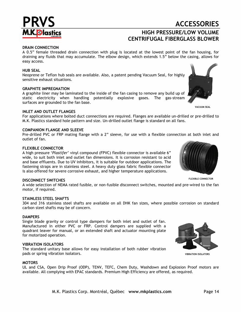
DRAIN CONNECTION A 0.5” female threaded drain connection with plug is located at the lowest point of the fan housing, for draining any fluids that may accumulate. The elbow design, which extends 1.5” below the casing, allows for easy access. HUB SEAL Neoprene or Teflon hub seals are available. Also, a patent pending Vacuum Seal, for highly sensitive exhaust situations. GRAPHITE IMPREGNATION A graphite liner may be laminated to the inside of the fan casing to remove any build up of static electricity when handling potentially explosive gases. The gas-stream surfaces are grounded to the fan base. INLET AND OUTLET FLANGES For applications where bolted duct connections are required. Flanges are available un-drilled or pre-drilled to M.K. Plastics standard hole pattern and size. Un-drilled outlet flange is standard on all fans. COMPANION FLANGE AND SLEEVE Pre-drilled PVC or FRP mating flange with a 2” sleeve, for use with a flexible connection at both inlet and outlet of fan. FLEXIBLE CONNECTOR A high pressure ‘Plastifer’ vinyl compound (FPVC) flexible connector is available 6” wide, to suit both inlet and outlet fan dimensions. It is corrosion resistant to acid and base effluents. Due to UV inhibitors, it is suitable for outdoor applications. The fastening straps are in stainless steel. A heavy duty glass fabric flexible connector is also offered for severe corrosive exhaust, and higher temperature applications. DISCONNECT SWITCHES A wide selection of NEMA rated fusible, or non-fusible disconnect switches, mounted and pre-wired to the fan motor, if required. STAINLESS STEEL SHAFTS 304 and 316 stainless steel shafts are available on all DHK fan sizes, where possible corrosion on standard carbon steel shafts may be of concern. DAMPERS Single blade gravity or control type dampers for both inlet and outlet of fan. Manufactured in either PVC or FRP. Control dampers are supplied with a quadrant leaver for manual, or an extended shaft and actuator mounting plate for motorized operation. VIBRATION ISOLATORS The standard unitary base allows for easy installation of both rubber vibration pads or spring vibration isolators. MOTORS UL and CSA, Open Drip Proof (ODP), TENV, TEFC, Chem Duty, Washdown and Explosion Proof motors are available. All complying with EPAC standards. Premium High Efficiency are offered, as required.
VIBRATION ISOLATORS
VACUUM SEAL
FLEXIBLE CONNECTOR
PRVS SPECIFICATIONS HIGH PRESSURE/LOW VOLUME
CENTRIFUGAL FIBERGLASS BLOWER
M.K. Plastics Corp. Montréal, Québec www.mkplastics.com Page 15
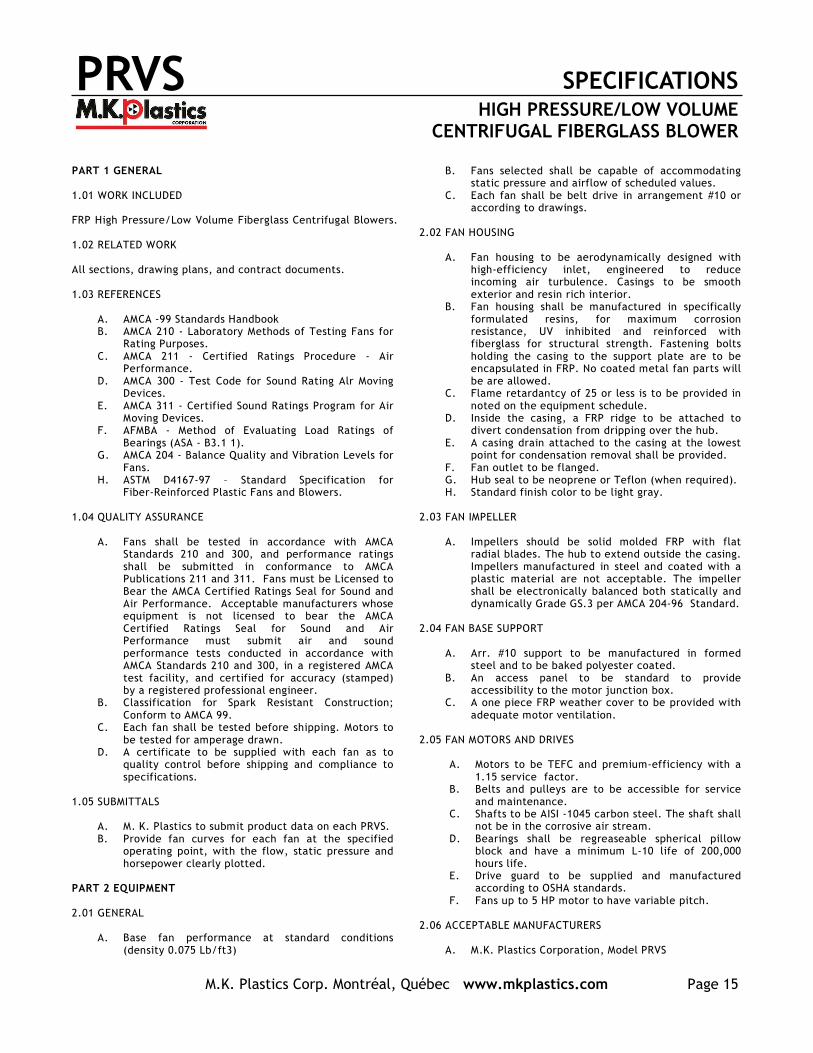
PART 1 GENERAL 1.01 WORK INCLUDED FRP High Pressure/Low Volume Fiberglass Centrifugal Blowers. 1.02 RELATED WORK All sections, drawing plans, and contract documents. 1.03 REFERENCES
A. AMCA -99 Standards Handbook B. AMCA 210 - Laboratory Methods of Testing Fans for
Rating Purposes. C. AMCA 211 - Certified Ratings Procedure - Air
Performance. D. AMCA 300 - Test Code for Sound Rating Alr Moving
Devices. E. AMCA 311 - Certified Sound Ratings Program for Air
Moving Devices. F. AFMBA - Method of Evaluating Load Ratings of
Bearings (ASA - B3.1 1). G. AMCA 204 - Balance Quality and Vibration Levels for
Fans. H. ASTM D4167-97 – Standard Specification for
Fiber-Reinforced Plastic Fans and Blowers. 1.04 QUALITY ASSURANCE
A. Fans shall be tested in accordance with AMCA Standards 210 and 300, and performance ratings shall be submitted in conformance to AMCA Publications 211 and 311. Fans must be Licensed to Bear the AMCA Certified Ratings Seal for Sound and Air Performance. Acceptable manufacturers whose equipment is not licensed to bear the AMCA Certified Ratings Seal for Sound and Air Performance must submit air and sound performance tests conducted in accordance with AMCA Standards 210 and 300, in a registered AMCA test facility, and certified for accuracy (stamped) by a registered professional engineer.
B. Classification for Spark Resistant Construction; Conform to AMCA 99.
C. Each fan shall be tested before shipping. Motors to be tested for amperage drawn.
D. A certificate to be supplied with each fan as to quality control before shipping and compliance to specifications.
1.05 SUBMITTALS
A. M. K. Plastics to submit product data on each PRVS. B. Provide fan curves for each fan at the specified
operating point, with the flow, static pressure and horsepower clearly plotted.
PART 2 EQUIPMENT 2.01 GENERAL
A. Base fan performance at standard conditions (density 0.075 Lb/ft3)
B. Fans selected shall be capable of accommodating static pressure and airflow of scheduled values.
C. Each fan shall be belt drive in arrangement #10 or according to drawings.
2.02 FAN HOUSING
A. Fan housing to be aerodynamically designed with high-efficiency inlet, engineered to reduce incoming air turbulence. Casings to be smooth exterior and resin rich interior.
B. Fan housing shall be manufactured in specifically formulated resins, for maximum corrosion resistance, UV inhibited and reinforced with fiberglass for structural strength. Fastening bolts holding the casing to the support plate are to be encapsulated in FRP. No coated metal fan parts will be are allowed.
C. Flame retardantcy of 25 or less is to be provided in noted on the equipment schedule.
D. Inside the casing, a FRP ridge to be attached to divert condensation from dripping over the hub.
E. A casing drain attached to the casing at the lowest point for condensation removal shall be provided.
F. Fan outlet to be flanged. G. Hub seal to be neoprene or Teflon (when required). H. Standard finish color to be light gray.
2.03 FAN IMPELLER
A. Impellers should be solid molded FRP with flat radial blades. The hub to extend outside the casing. Impellers manufactured in steel and coated with a plastic material are not acceptable. The impeller shall be electronically balanced both statically and dynamically Grade GS.3 per AMCA 204-96 Standard.
2.04 FAN BASE SUPPORT
A. Arr. #10 support to be manufactured in formed steel and to be baked polyester coated.
B. An access panel to be standard to provide accessibility to the motor junction box.
C. A one piece FRP weather cover to be provided with adequate motor ventilation.
2.05 FAN MOTORS AND DRIVES
A. Motors to be TEFC and premium-efficiency with a 1.15 service factor.
B. Belts and pulleys are to be accessible for service and maintenance.
C. Shafts to be AISI -1045 carbon steel. The shaft shall not be in the corrosive air stream.
D. Bearings shall be regreaseable spherical pillow block and have a minimum L-10 life of 200,000 hours life.
E. Drive guard to be supplied and manufactured according to OSHA standards.
F. Fans up to 5 HP motor to have variable pitch. 2.06 ACCEPTABLE MANUFACTURERS
A. M.K. Plastics Corporation, Model PRVS
4955 De Courtrai Ave., Montreal, Quebec H3W 1A6Trimex Building, Route 11, Mooers, NY 12958
Spiez, Switzerland tel: (514) 871-9999 / (888) 278-9988
fax: (514) 871-1753www.mkplastics.com25-01-MARCH 2008
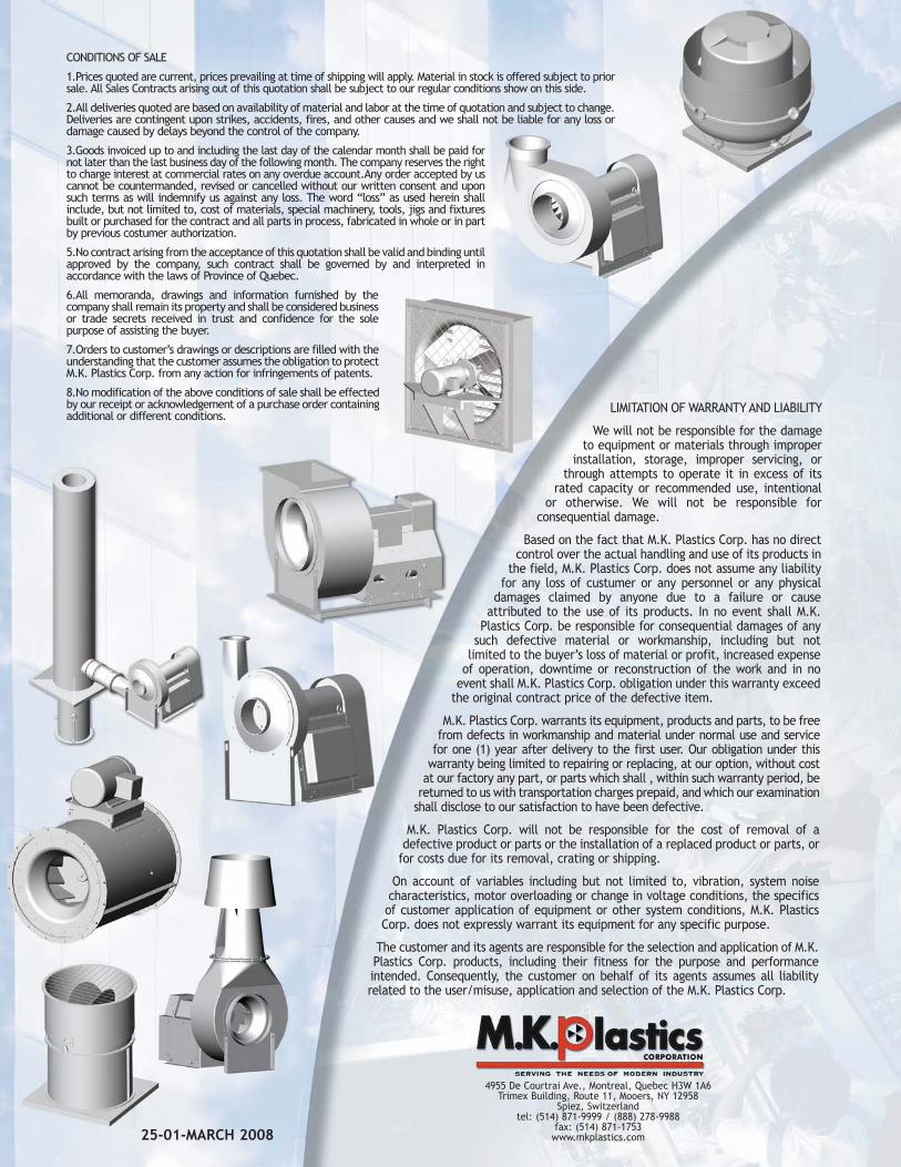
LIMITATION OF WARRANTY AND LIABILITY
We will not be responsible for the damageto equipment or materials through improper
installation, storage, improper servicing, orthrough attempts to operate it in excess of its
rated capacity or recommended use, intentionalor otherwise. We will not be responsible for
consequential damage.
Based on the fact that M.K. Plastics Corp. has no directcontrol over the actual handling and use of its products in
the field, M.K. Plastics Corp. does not assume any liabilityfor any loss of custumer or any personnel or any physical
damages claimed by anyone due to a failure or causeattributed to the use of its products. In no event shall M.K.
Plastics Corp. be responsible for consequential damages of anysuch defective material or workmanship, including but not
limited to the buyer’s loss of material or profit, increased expenseof operation, downtime or reconstruction of the work and in no
event shall M.K. Plastics Corp. obligation under this warranty exceedthe original contract price of the defective item.
M.K. Plastics Corp. warrants its equipment, products and parts, to be freefrom defects in workmanship and material under normal use and service
for one (1) year after delivery to the first user. Our obligation under thiswarranty being limited to repairing or replacing, at our option, without cost
at our factory any part, or parts which shall , within such warranty period, bereturned to us with transportation charges prepaid, and which our examination
shall disclose to our satisfaction to have been defective.
M.K. Plastics Corp. will not be responsible for the cost of removal of adefective product or parts or the installation of a replaced product or parts, or
for costs due for its removal, crating or shipping.
On account of variables including but not limited to, vibration, system noisecharacteristics, motor overloading or change in voltage conditions, the specificsof customer application of equipment or other system conditions, M.K. PlasticsCorp. does not expressly warrant its equipment for any specific purpose.
The customer and its agents are responsible for the selection and application of M.K.Plastics Corp. products, including their fitness for the purpose and performanceintended. Consequently, the customer on behalf of its agents assumes all liabilityrelated to the user/misuse, application and selection of the M.K. Plastics Corp.
CONDITIONS OF SALE
1.Prices quoted are current, prices prevailing at time of shipping will apply. Material in stock is offered subject to priorsale. All Sales Contracts arising out of this quotation shall be subject to our regular conditions show on this side.
2.All deliveries quoted are based on availability of material and labor at the time of quotation and subject to change.Deliveries are contingent upon strikes, accidents, fires, and other causes and we shall not be liable for any loss ordamage caused by delays beyond the control of the company.
3.Goods invoiced up to and including the last day of the calendar month shall be paid fornot later than the last business day of the following month. The company reserves the rightto charge interest at commercial rates on any overdue account.Any order accepted by uscannot be countermanded, revised or cancelled without our written consent and uponsuch terms as will indemnify us against any loss. The word “loss” as used herein shallinclude, but not limited to, cost of materials, special machinery, tools, jigs and fixturesbuilt or purchased for the contract and all parts in process, fabricated in whole or in partby previous costumer authorization.
5.No contract arising from the acceptance of this quotation shall be valid and binding untilapproved by the company, such contract shall be governed by and interpreted inaccordance with the laws of Province of Quebec.
6.All memoranda, drawings and information furnished by thecompany shall remain its property and shall be considered businessor trade secrets received in trust and confidence for the solepurpose of assisting the buyer.
7.Orders to customer’s drawings or descriptions are filled with theunderstanding that the customer assumes the obligation to protectM.K. Plastics Corp. from any action for infringements of patents.
8.No modification of the above conditions of sale shall be effectedby our receipt or acknowledgement of a purchase order containingadditional or different conditions.