design and simulation of centrifugal blower using ...ijpres.com/pdf16/8.pdf · design and...
TRANSCRIPT
INTERNATIONAL JOURNAL OF PROFESSIONAL ENGINEERING STUDIES Volume V /Issue 3 /AUG 2015
IJPRES
DESIGN AND SIMULATION OF CENTRIFUGAL BLOWER USING COMPOSITE
MATERIALS
1 SAI RAGHU VEMURI, 2 P.V VISWANATH
1 PG Scholar, Department of MECH, Vidya Jyothi Institute of Technology, RangaReddy, Telangana, India. 2 Associate Professor, Department of MECH, Vidya Jyothi Institute of Technology, RangaReddy, Telangana, India.
Abstract— Centrifugal blowers are used in
naval applications and motors. The Contemporary blades
in Centrifugal Blower used in naval applications are
made up of Aluminum or Steel. It is proposed to design a
blower using Computer Aided Design (CAD) software
with various metal alloys and Non-Metallic composite
materials, analyze its strength and deformation using
simulation software. In order to evaluate the
effectiveness of Metal Alloys and Non-Metallic
composites.
The present work aim is to change the material and
performing the different analysis like Static, Dynamic,
Flow Simulation & Cost Analysis to find the best
material to decrease the weight and increase its efficiency
by using the software SOLID WORKS.
Key Words:
Centrifugal Blower, Computer Aided Design (CAD), Metal Alloys, Non-Metallic Composite Materials, SOLIDWORKS, Simulation Analysis.
I INTRODUCTION
A centrifugal blower is a mechanical device for moving air
or other gases. The terms "blower" and "squirrel cage fan"
(because it looks like a hamster wheel) are frequently used
as synonyms. Rotating impellers increase the speed of the
air blowing from other end.
They use the kinetic energy of the rotating blade or
impeller to increase the pressure and tends to slightly
decrease velocity of the air/gas stream which in turn moves
them against, dampers and other components which causes
the resistance. Centrifugal fans accelerate air radically,
changing the direction (typically by 90°) of the airflow.
They are quiet, sturdy, capable, and reliable of operating
over a wide range of critical conditions.
Centrifugal blowers are constant volume or displacement
devices, at a constant fan speed, centrifugal blowers will
pump a volume of air constantly irrespective with the
constant mass rate. This means that the air velocity in a
system is fixed even though mass flow rate through the fan
is not.
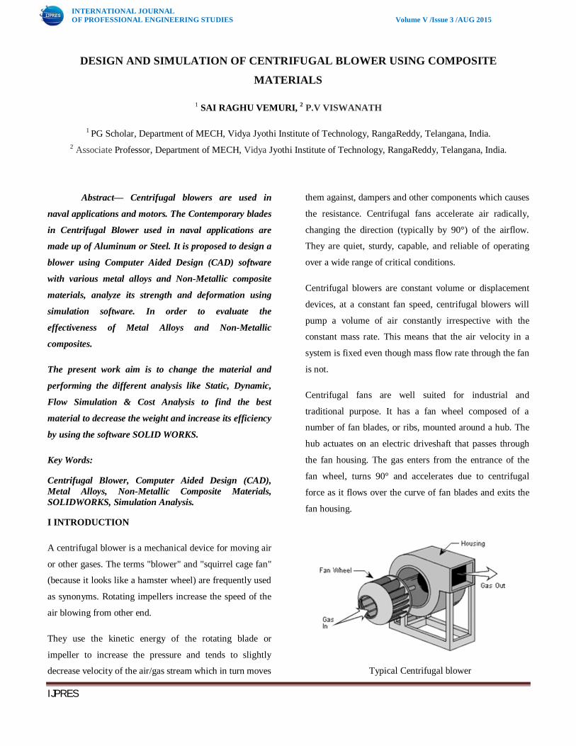
Centrifugal fans are well suited for industrial and
traditional purpose. It has a fan wheel composed of a
number of fan blades, or ribs, mounted around a hub. The
hub actuates on an electric driveshaft that passes through
the fan housing. The gas enters from the entrance of the
fan wheel, turns 90° and accelerates due to centrifugal
force as it flows over the curve of fan blades and exits the
fan housing.
Typical Centrifugal blower

INTERNATIONAL JOURNAL OF PROFESSIONAL ENGINEERING STUDIES Volume V /Issue 3 /AUG 2015
IJPRES
Types of blowers Blowers can achieve much higher pressures than fans and
also produce negative pressures for industrial vacuum
systems. Main types of blowers ,which are described
below.
a) Centrifugal blower
b) Positive-Displacement Blower
Blower efficiency and performance:
Blower efficiency is the ratio between the power
transferred to the airstream and the power delivered by
the motor to the Blower. The power of the air flow is the
product of the pressure and the flow, corrected for unit
consistency.
Another term for efficiency that is often used with fans
is static efficiency, which uses static pressure instead of
total pressure in estimating the efficiency. When
evaluating fan performance, it is important to know
which efficiency term is being used.
The Blower efficiency depends on the type of fan and
impeller. As the flow rate increases, the efficiency
increases to certain height (“peak efficiency”) and then
decreases with further increasing flow rate. The peak
efficiency ranges for different types of centrifugal and
axial fans are given
Efficiency of Various Fans
Centrifugal Blower working principle
Centrifugal force is used as a main principle for the kinetic
energy produced by the impeller to the air/gas which is
used as a fluent. By this principle the gas enters in to the
impeller and thrown off by creating kinetic energy at the
exit. As a result, the pressure is measured in terms of
kinetic energy because of casting and duct which offers
system resistance. The gas is then guided to the exit via
outlet ducts. The gas pressure in the middle region of the
impellers decreases after it is thrown off. The cycle repeats
when the gas from the impeller eye rushes and therefore
the same volume of gas can be continuously transferred.
Velocity triangle: A diagram called a velocity triangle helps us in
determining the flow geometry at the entry and exit of a
blade. A minimum number of data are required to draw a
velocity triangle at a point on blade. Some component of
velocity varies at different point on the blade due to
changes in the direction of flow. Hence an infinite number
of velocity triangles are possible for a given blade. In order
to describe the flow using only two velocity triangles we
define mean values of velocity and their direction.
Velocity triangle of any turbo machine has three
components as shown.

INTERNATIONAL JOURNAL OF PROFESSIONAL ENGINEERING STUDIES Volume V /Issue 3 /AUG 2015
IJPRES
Velocity triangle for forward facing blade
These velocities are related by the triangle law of vector
addition: V= U+Vr
Where U= Blade velocity
Vr= Relative Velocity
V= Absolute velocity
Scope and objective of present work:
The Contemporary blades in Centrifugal Blower used in
naval applications are made up of Aluminum or Steel. The
objective of present work is to design a Impeller of a
Centrifugal blower with four materials, which are:
(a) Aluminum Alloy 1060
(b) Graphite
(c) Titanium
(d) E-glass/Epoxy
To analyze which material made impeller gives
better results in terms weight, Output pressure, Out-put
velocity, Breaking point, efficiency and cost-friendly.
These results can be obtained by performing the following
analysis on each material type.
(a) Static Analysis.
(b) Dynamic Analysis.
(c) Computational fluid dynamic (CFD)
Analysis.
(d) Cost analysis.
(e) Weight Analysis.
The modeling of the impeller and the above
mentioned analyses will be done by Solidworks software.
In addition to that a method to fabricate the Impeller with
E-glass/Epoxy is studied for realization of product.
LITERATURE REVIEW
(Dr). M.L Kulkarni has developed strategy and design procedure for blower which is expected to bring down the lead time during designing through the Reverse Engineering approach. The different dimensions & geometry of parts of the existing blower were found out by obtaining the Cartesian coordinates of various identified points. Thereafter the required profile and models were developed using this data with the help of CATIA V5 modeler. The Suction condition and other related data’s such as “inlet & outlet diameter”, “inlet & outlet vane angles” & “vane width” at the inlet and outlet were used to calculate specific data’s such as “Absolute velocity of the jet”, “velocity at the inlet and outlet”, “whirl velocity at outlet” and “exit angle of jet at the vane”. The project also covers areas of Geometric Analysis, Fluid Dynamics and Concept of Curve Generation
THEORITICAL CALCULATION:
Attempts are made to address this issue through considering the input values as below. Sl. No. Parameters Values
1 θ 40o 2 ф 50o 3 N 1300 rpm 4 b1 53.4 mm 5 b2 58.4 mm 6 r1 16.25 mm 7 r2 295 mm 8 R 381 mm 9 Blade curve Parabolic
ଵݑ = ଵݎ × ߱

INTERNATIONAL JOURNAL OF PROFESSIONAL ENGINEERING STUDIES Volume V /Issue 3 /AUG 2015
IJPRES
ଶݑ = ଶݎ × ߱
tan θ = v1/u1, v1 = vf1
Q = 2πr1b1v1
Vf2 = Q/2πr2b2
By using the above mentioned equations and input values, the following values were calculated:
Angular velocity ߱ = 136.13 rad/sec
Vane velocity at inlet u1 = 2.212 m/s
Vane velocity at outlet u2 = 29.4 m/s
Velocity of flow at inlet vf1 = v1 =292 m/s
Velocity of flow at outlet vf2 = 26.17 m/s
Discharge Q = 1.592 m/s
Whirl velocity at outlet Vw2= 12.47
ANALYSIS & DATA COLLECTION:
Material properties:
MODELLING AND SIMULATION:
Static Analysis on impeller of Al Alloy 1060:
Model with volumetric properties of AA1060
Applying Loads and fixtures
Applying Loads and Fixtures on impeller of AA1060

INTERNATIONAL JOURNAL OF PROFESSIONAL ENGINEERING STUDIES Volume V /Issue 3 /AUG 2015
IJPRES
Meshing:
Mesh information of AA1060
Meshed model of AA 1060
Static stress, Strain and total deformation values
Static stress result table of AA1060
Strain result of AA 1060
Total deformation table of AA1060
Dynamic Analysis
Dynamic Analysis on impeller of Al Alloy 1060:
Applying Loads and fixtures
Applying Loads and Fixtures on impeller of Al Alloy 1060 Dynamic Stress, Total deformation and Mass participation:
Dynamic stress result table of Al Alloy 1060
INTERNATIONAL JOURNAL OF PROFESSIONAL ENGINEERING STUDIES Volume V /Issue 3 /AUG 2015
IJPRES
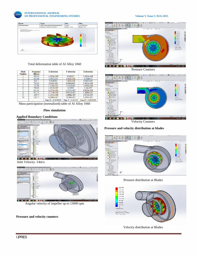
Total deformation table of Al Alloy 1060
Mass participation (normalized) table of Al Alloy 1060
Flow simulation
Applied Boundary Conditions
Inlet Velocity -14m\s
Angular velocity of impeller up to 13000 rpm
Pressure and velocity counters
Pressure Counters
Velocity Counters
Pressure and velocity distribution at blades
Pressure distribution at Blades
Velocity distribution at Blades

INTERNATIONAL JOURNAL OF PROFESSIONAL ENGINEERING STUDIES Volume V /Issue 3 /AUG 2015
IJPRES
Pressure and velocity flow trajectories:
Pressure flow trajectories
Velocity flow trajectories
As we observe the pressure counters, it is shown that the pressure is slightly decreased at the outlet due to the peek efficiency reached by the flow rate.
Cost analysis:
RESULTS, DISCUSSIONS AND CONCLUSIONS
Static Stress analysis results
Load applied on each material was 1500N
Minimum stress (N/M2) Vs. Material
Maximum stress (N/M2) Vs. Material
Deformation (Mm) Vs. Material
Dynamic analysis Results
Load applied on each material was 1500N

INTERNATIONAL JOURNAL OF PROFESSIONAL ENGINEERING STUDIES Volume V /Issue 3 /AUG 2015
IJPRES
Minimum stress (N/M2) Vs. Material
Maximum stress (N/M2) Vs. Material
Deformation (Mm) Vs. Material
Flow Analysis Result
It is observed that the Velocity at out let is decreased
compared to inlet and Pressure increases at the outlet, due
to the peek effect.
Cost Analysis Result:
Material Cost
Manufacturing Costs
Total Costs

INTERNATIONAL JOURNAL OF PROFESSIONAL ENGINEERING STUDIES Volume V /Issue 3 /AUG 2015
IJPRES
Weight Analysis Result:
Weight Density Vs. Material
CONCLUSION
Modeling and simulation of centrifugal blower fan has done using Solid Works software.
After observing the static and dynamic analysis values we can conclude that e-epoxy has the better stress bearing capacity compared with the other materials except titanium deformation values by showing its better strength values to the applied loads.
During Flow simulation at impeller output velocity is decreased compared to inlet velocity, where as output pressure is increased compared to inlet pressure.
By using cost analysis methods, the material cost of each metal is noted shown in graphs and we can observe that cost of e-epoxy is slightly more than aluminum and this can be reduced in long run of manufacturing.
E-glass/Epoxy material is non metallic component so, the chattering noise will be low compared to other materials during the functioning process.
For manufacturing the centrifugal blower impeller we can proceed with Epoxy/E-glass material because it has high stress bearing capacity and reasonable manufacturing cost. FUTURE SCOPE:
CFD analysis of different types of impellers with change of RPM
The composition of e-epoxy can be changed with optimum composition of the resin and hardeners, So that the maximum stress acting on the material may reduce which proportionally decreases the deformation.
REFERENCES [1] S.Rajendran and Dr.K.Purushothaman, “Analysis of a centrifugal pump impeller using ANSYS-CFX,” International Journal of Engineering Research & Technology, Vol. 1, Issue 3, 2012.
[2] S R Shah, S V Jain and V J Lakhera, “CFD based flow analysis of centrifugal pump,” Proceedings of the 37th National & 4th International Conference on Fluid Mechanics and Fluid Power, IIT Madras, Chennai, 2010.
[3] P.Usha Shri ans C.Syamsundar, “computational analysis on performance of a centrifugal pump impeller,” Proceedings of the 37th National & 4th International Conference on Fluid Mechanics and Fluid Power, IIT Madras, Chennai, 2010.
[4] E.C. Bacharoudis, A.E. Filios, M.D. Mentzos and D.P. Margaris, “Parametric Study of a Centrifugal Pump Impeller by Varying the Outlet Blade Angle,” The Open Mechanical Engineering Journal, no 2, 75-83, 2008.
[5] Marco Antonio Rodrigues Cunh and Helcio Francisco Villa Nova, “Cavitation modelling of a centrifugal pump impeller,” 22nd International Congress of Mechanical Engineering, Ribeirao Petro, Sao Paulo, Brazil, 2013.
[6] Mohammed Khudhair Abbas, “cavitation in centrifugal pumps,” Diyala Journal of Engineering Sciences, pp. 170-180, 2010.
[7] Abdulkadir Aman, Sileshi Kore and Edessa Dribssa, “Flow simulation and performance prediction of centrifugal pumps using cfd-tool,” Journal of EEA, Vol. 28, 2011.
[8] Erik Dick, Jan Vierendeels, Sven Serbruyns and John Vande Voorde, “Performance prediction of centrifugal pumps with cfd-tools,” Task Quarterly 5, no 4, 579–594, 2001.
[9] S. C. Chaudhari, C. O. Yadav and A. B. Damo, “A comparative study of mix flow pump impeller cfd analysis and experimental data of submersible pump,” International Journal of Research in Engineering & Technology, Vol. 1, Issue 3, 57-64, 2013.
[10] D. Somashekar and Dr. H. R. Purushothama, “Numerical Simulation of Cavitation Inception on Radial Flow Pump,” IOSR Journal of Mechanical and Civil Engineering, Vol. 1, Issue 5, pp. 21-26, 2012.
[11] Liu Houlin, Wang Yong, Yuan Shouqi, Tan Minggao and Wang Kai, “Effects of Blade Number on Characteristics of Centrifugal Pumps,” Chinese journal of mechanical engineering, Vol. 23, 2010.
[12] Myung Jin Kim, Hyun Bae Jin, and Wui Jun Chung, “A Study on Prediction of Cavitation for Centrifugal Pump,” World Academy of Science, Engineering and Technology, Vol. 6, 2012.