high-pressure, high-temperature well construction - schlumberger
TRANSCRIPT

36 Oilfield Review
High-Pressure, High-Temperature Well Construction
Keelan AdamsonGeorge BirchErhu GaoSteve HandColin MacdonaldDavid MackAnver QuadriAberdeen, Scotland, UK
For help in preparation of this article, thanks to JohnOliver, Dowell, Sugar Land, Texas, USA; and DemosPafitis, Anadrill, Sugar Land, Texas.CemCADE, DensCRETE, FMP (Drilling fluids monitoringpackage), MudCADE, MUDPUSH, PRISM (precisionrecording for job supervision and monitoring) andULTIDRILL are marks of Schlumberger.
Drilling and completing wells in HPHT environments is difficult and dangerous. But as
activity in these areas expands, transfering experience, expertise and knowledge
about the best techniques from person to person and well to well is essential to
reduce risks, increase safety and efficiency, and ultimately, improve financial returns.

Summer 1998 37
The principles of well construction in high-pressure, high-temperature (HPHT) wells arenot significantly different from those used inless demanding wells, but challenges remainbecause of conditions that limit the range ofsuitable materials and affect equipmentperformance. The margins for error are small and the potential consequences of fail-ure are great.
Despite the challenges, interest in thesewells has remained high and the number ofHPHT wells has grown steadily. Reservoirpressures in excess of 10,000 psi [68.9 MPa]have been exploited in many parts of theworld, particularly in the search for gas.High-temperature wells have been success-fully drilled into reservoirs where tempera-tures exceed 300°F [149°C] in Qatar, Ras alKhaimah, Sudan and elsewhere. In Chinaexploitation of 500°F [260°C] reservoirs isbeing planned for 1998.
Even more challenging conditions existwhere high pressures and temperatures arepresent together as in Angola, the USA,Yemen and the North Sea. In these regions itis not uncommon for well temperaturesexceeding 350°F [177°C] to coexist withpressure gradients requiring mud weights inexcess of 16 ppg [1.9 g/cm3]. The mostextreme wells in the North Sea (Ranger well29/5B-4), Yemen (Shell Abbass 1 well) and the USA (Sohio M.E. Coward well) have temperatures above 400°F [204°C]drilled with muds of up to 18.5 ppg [2.22 g/cm3] (above).
Even with growing experience, manyaspects of drilling and completing HPHTwells continue to demand special attention.For example, secondary well control relies on
surface equipment being able to function reli-ably under extreme conditions. Blowout pre-venter (BOP) elastomers and flexible hosesmust be rated to withstand the temperaturesand pressures for long enough to evacuate arig during the worst-case scenario (often con-sidered to be complete expulsion of drillingfluid from the well after loss of well control).
Evaluating HPHT wells requires speciallogging and testing tools, with downholemechanical and electrical equipmentcapable of withstanding harsh conditions ofelevated temperature and pressure, high-temperature explosives for perforating, andprocedures for their successful operation.These aspects of exploiting HPHT wells areaddressed elsewhere in this issue (see “High-Pressure, High-Temperature WellLogging, Perforating and Testing,” page 50).
Oilfield Review first evaluated HPHTdrilling in 1993.1 Much progress has beenmade in the last five years. This article exam-ines recent advances in HPHT well construc-tion, drilling fluids and cementing techniques,with examples of procedures and guidelinesfor routine and contingency actions. We eval-uate current well-control practices thatemphasize the application of computer simu-lations to model downhole temperatures anddrilling fluid properties. When combined withsophisticated hydraulic models, these simula-tions help well engineers reliably predictdownhole pressures to within 1% of theactual conditions. Techniques for measure-ment of drilling fluid parameters at surface tothe same accuracy complement the models,permitting control of fluid properties and ulti-mately downhole pressures. Finally, wereview new cementing practices developedspecifically for HPHT wells.
Planning for SuccessMost of the hazards of drilling HPHT wellsare related to overpressured formations.Ideally, such wells would be drilled withhigh enough mud weight to give a comfort-able safety margin over pore pressure. Themud engineer’s job in formulating the mudwould then be relatively straightforward:minimize formation damage and maximizerate of penetration.
An overpressured formation becomes amajor problem when the formation fracturepressure is close to that in the overpressuredzone. This results in drilling conditionswhere kicks are easily taken, and wherefractures can be inadvertently initiated,resulting in drilling fluid losses that are diffi-cult to control.
These problems are clearly illustrated in theElgin and Franklin fields, operated by ElfExploration UK Plc, in the North Sea approx-imately 240 km [150 miles] east of Aberdeen,Scotland.2 Reservoirs in the Upper JurassicFranklin sands and the Middle JurassicPentland sands are hot (up to 392°F [200°C])and deep (18,370 ft [5600 m]). The pressuregradient exhibits a marked increase below the
■HPHT well locationsworldwide. HPHT wellsare concentrated in theUS Gulf Coast and theNorth Sea, where reser-voir pressures of 16,000psi and bottomholetemperatures of 350°Fare common. In Thai-land, more than 45high-temperature wellshave been drilled.
1. MacAndrew R, Parry N, Prieur J-M, Wiggelman JH,Diggins E, Guichency P, Cameron D and Stewart A:“Drilling and Testing Hot, High-Pressure Wells,”Oilfield Review 5, no. 2/3 (April/July 1993): 15-32.
2. Gibson MT, Bergerot J-L and Humphreys A:“Developing a Greater Understanding of the WellHydraulics in HP/HT Wells: An Updated Study of the Wells in the Elgin/Franklin Fields,” presented atDrilling ‘96: The 4th Annual Industry Forum,Aberdeen, UK, March 27-28, 1996.Houwen OH and Geehan T: “Rheology of Oil-BaseMuds,” paper SPE 15416, presented at the 61st SPEAnnual Technical Conference and Exhibition, NewOrleans, Louisiana, USA, October 5-8, 1986.

1000
2000
3000
4000
5000
Formation pressure, psiFormation
1.0 Formation pressure gradient, psi/ft
Formation pressure gradient, MPa
1.5 2.0 2.5
NO
RD
LAN
D
Vert
ical
dep
th, m
EO
CE
NE
PAL
UP
PE
R C
RE
TAC
EO
US
LCU
. JU
RA
SS
ICM
J
FRA
NK
LIN
PE
NTL
AN
D
CLA
YS
TON
ES
DS
T
4000
4500
5000
5500
Pressure, psi
Pressure, MPa
Transition Zone Pressures
Formation
Hydrostatic
Fracture
Unconformity
0 1450 2900 4350 5800 7250 8700 10,150 11,600 13,050
0 10 20 30 40 50 60 70 80 90
0 10 20 30 40 50 60 70 80 90
1450 4350 7250 10,150
Vert
ical
dep
th, m
CH
ALK
GR
OU
P (L
MS
T)C
LST
HO
RD
LAN
DB
ALD
ER
ME
KO
FIS
KTO
RH
OD
HE
RR
HID
KIM
M
38 Oilfield Review
Kimmeridge claystone with reservoir pressureof 16,330 psi [112.5 MPa] (below). These con-siderable drilling challenges are compoundedby the small margin—approximately 1400 psi[9650 kPa]—between fracture and pore pres-sure in the lowermost intervals. A 1400-psihydrostatic pressure window at 15,000 ft[4750 m] corresponds to a small increment inmud weight of 1.8 ppg [0.22 g/cm3]. Similarconditions—with even smaller margins—exist in other North Sea wells, such as those inthe Heron project operated by Shell Expro,and in other HPHT fields around the world.
Above all other considerations, risk reduc-tion drives the planning needed to overcomethese challenges. Given the potential haz-
ards and costs, experience gained in previ-ous operations must be channeled into max-imizing safety, eliminating unproductivetime and increasing efficiency. With HPHTwell costs of $20 million becoming relativelycommon, and with HPHT rig rates amongthe highest in the industry, time spent cor-recting well-control problems is expensive.
The cornerstone of this preventive planningis the transfer of HPHT experience, capturedin guidelines, procedures and checklists.Some countries have legislation or govern-ment recommendations to guide operators;other procedures are based on industry bestpractices. An example is the UK Institute ofPetroleum “Model Code of Safe Practice” forHPHT wells.3 In addition to formal guide-lines, North Sea operators usually seek inputfrom contractors and others experienced inHPHT well construction.
Shell Expro, and its lead contractor SedcoForex, adopted the policy of mobilizingexperienced crews in advance of particularlychallenging projects, such as their North SeaMallard and Heron field developments. Thispolicy ensures that HPHT crews have hadprevious experience working as a team onless challenging wells, which is seen as asound investment in achieving a satisfactoryoutcome on subsequent HPHT wells.
In planning the detailed program for theMallard wells, Sedco Forex, Shell Expro andother subcontractors met to work through
procedures for all critical eventualities andproduced a comprehensive, practical HPHTmanual.4 Open communication throughoutthe discussions helped to achieve a consensuson best practices. One- and two-day trainingcourses familiarized personnel with the pro-cedures, along with refresher sessions on therig. Feedback during the training sessions andas actual operations progress results in refine-ments and improvements to procedures.
Much of the Mallard HPHT manual com-prises procedures for drilling, well control,suspension or abandonment, and emergencyplanning—along with descriptions of person-nel responsibilities. For example, the manualspells out the need for skilled personnel toensure continuous and diligent monitoring ofkey parameters when drilling the reservoirsection. Another requirement to minimize the number of unnecessary personnel onboard is common to most HPHT operations.A balance is needed. Equally important is the description of communications. “Non-routine” operations meetings, for example,are required to discuss any nonstandardoperations and ensure that all parties clearlyunderstand the program and their roles in it.
During routine drilling operations thehand-over between crew shifts must becontrolled, because any small change in observed drilling parameters might indi-cate a large potential problem. In addition to specifying a routine pretour meeting, the HPHT manual provides checklists toensure that essential information and trends
■Elgin pressure gradient. Overpressured intervals are char-acteristic of HPHT wells. The formation pressure gradient(left) is from the Elgin field in the Central Graben area ofthe UK Sector of the North Sea. The top of the overpressuredgas/condensate reservoirs of the Upper Jurassic Franklinsands and Middle Jurassic Pentland sands reaches 380°Fwith absolute static pressures greater than 16,000 psi. Anunconformity at the base of the Lower Cretaceous (LC) for-mation coincides with the shale that is responsible for theoverpressure. The inset shows the predicted hydrostaticpressure near TD as well depth increases. A large increasein mud weight is needed at 5100 m to control formationpressure. However, hydrostatic pressure then approachesfracture pressure. Achieving adequate hydrostatic pressurewhile avoiding fracturing the formation is a challenge forthe HPHT mud engineer.
Summer 1998 39
are communicated. An example is thedriller’s “Tour Checklist,” which requires thedriller to carry out a physical check of muddensity, viscosity and temperature every 15 minutes up to the tour change, and com-municate this information to the mud engi-neer, mud logger and drillers, as well as tothe new crew. Frequent checks of thesecritical parameters may reveal any earlysigns of potential trouble.
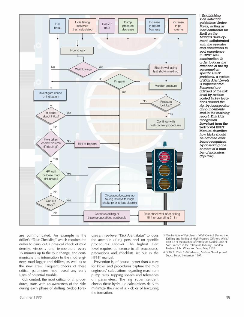
Kick control, the most critical of all proce-dures, starts with an awareness of the risksduring each phase of drilling. Sedco Forex
uses a three-level “Kick Alert Status” to focusthe attention of rig personnel on specificprocedures (above). The highest alert level requires adherence to all procedures,precautions and checklists set out in theHPHT manual.
Prevention is, of course, better than a curefor kicks, and procedures capture the mudengineers’ calculations regarding maximumpump rates, tripping speeds and toleranceson parameters. The rig superintendentchecks these hydraulic calculations daily tominimize the risk of a kick or of fracturingthe formation.
Drillbreak
Hole takingless mud
than calculated
Gas cutmud
Pumppressuredecrease
Increasein returnflow rate
Increasein pit
volume
Shut in well usingfast shut-in method
Continue withwell-control procedures
Continue drilling ortripping operations cautiously
Circulating bottoms uptaking returns through
choke prior to bubblepoint
Investigate causeof indication
Monitor pressure
RIH to bottom
Flow check
Pressurebuildup?
In doubtabout influx?
Hole takencorrect volume
(if tripping)?
HP well oil-base muddrill break?
Gas cutmud?
Well flowing?Yes
Yes
Yes
Yes
No
No
Yes
Yes
Yes
No
No
No
No
NoPit gain?
Flow check well after drilling15 ft or operating 5min
■Establishingkick detectionguidelines. SedcoForex, acting aslead contractor forShell on the Mallard develop-ment, collaboratedwith the operatorand contractors topool experience in HPHT well construction. Inorder to focus the attention of the rigpersonnel on specific HPHT problems, a systemof Kick Alert Levelsis implemented.Personnel areadvised of the risklevel by noticesposted in key loca-tions around therig, by loudspeakerannouncementsand in the morningreport. This kickrecognitionflowchart from theSedco 704 HPHTManual describeshow kicks shouldbe handled afterbeing recognizedby observing oneor more of a num-ber of indicators(top row).
3. The Institute of Petroleum: “Well Control During theDrilling and Testing of High Pressure Offshore Wells,”(Part 17 of the Institute of Petroleum Model Code ofSafe Practice in the Petroleum Industry), London,England: John Wiley and Sons, May 1992.
4. SEDCO 704 HP/HT Manual, Mallard Development.Sedco Forex, November 1997.
40 Oilfield Review
Similar procedures were in place duringthe recent drilling of three Heron wells forShell Expro. Not a single kick was takenwhen drilling the reservoir sections, and thissuccess was largely attributed to the thor-oughness of the procedures established tocontrol drilling parameters, such as trippingspeeds. On the one occasion that a kick wastaken when drilling above the reservoir in aMallard well, it was detected after only 8 bbl[1.3 m3] flowed, allowing prompt action to control it.
In some cases, the conflicting demands of pore pressure and fracture pressure aredifficult to reconcile, and a risk analysis maybe needed to determine which one is moreimportant to address. An informed decisionmight be made to risk fracturing the forma-tion, rather than take a kick, based on the rel-ative ease with which fractures can beplugged or cemented.
Drilling Fluid PropertiesHole cleaning and control of formation pres-sures are critical functions of the drilling fluid.These are achieved when the mud pressure issufficient to hold back pore pressure and theviscosity is sufficient to transport cuttings fromthe bit to surface. Viscosity must also be suffi-cient to hold mud solids in suspension.5
Conventional calculations of downholepressure, which assume constant drillingfluid properties, are both practical for day-to-day use and accurate enough for routinewells. Downhole static pressures are easy to calculate from mud weight measured atsurface, while additional pressures due tocirculation can be calculated using estab-lished relationships between pump rate anddrilling fluid rheological properties.
Errors that result from ignoring variations inmud properties are small in relatively shal-low wells. In these settings, mud engineerscan concentrate on formulating drilling fluidproperties for maximum rates of penetrationand optimal hole condition. Formations cancommonly withstand moderate overpressurebefore being fractured, which permits mudengineers to add a comfortable safety marginwhen weighting the mud.
However, mud properties do vary withdownhole pressure and temperature, affect-ing the accuracy of both surface measure-ments and downhole estimations of mudweight and viscosity. In HPHT wells thesevariations can be significant because of thelimited safety margins available.
Clearly the ability to predict these effects iscritical to the successful drilling of HPHTwells. Small but serious errors in computingthe drilling fluid pressure at the reservoirmay result from ignoring uncertainties due toeither temperature or fluid properties.Simulation of downhole temperature profilesat all phases of the drilling operation is there-fore the key to understanding the behavior ofHPHT drilling fluids.
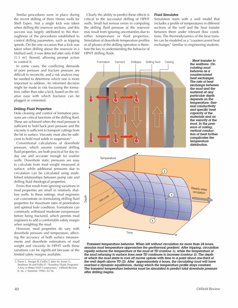
Fluid SimulatorSimulation starts with a well model thatincludes a profile of temperatures in differentsections of the well and the heat transferbetween them under relevant flow condi-tions. The thermodynamics of the heat trans-fer can be modeled as a “countercurrent heatexchanger,” familiar to engineering students.
Drilling fluidFormation Cement CasingDrillpipe ■Heat transfer tothe wellbore. Cir-culating mudbehaves as acountercurrentheat exchanger.The rate of heatexchange betweenthe mud and thematerial at anyparticular depthdepends on thetemperature, ther-mal conductivityand specific heatcapacity of thematerials and onthe velocity of themud. In the pres-ence of casing,vertical conduc-tion of heat furthercomplicates thetemperature distribution.
Time
Temperature
Dep
th
Steady-statecirculation
Static profile
1
2
3
■Transient temperature behavior. When left without circulation for more than 24 hours,annulus mud temperature approaches the geothermal gradient. After tripping, circulationrapidly reduces the temperature of the mud at TD (contour 1), while the temperature of the mud returning to surface from near TD continues to increase (contour 2). The depth at which the mud starts to cool off moves uphole with time to a point about one-third of the well depth above TD (3). After approximately 6 hours, the circulating mud will havereached a dynamic equilibrium, during which the temperature profile stays constant. The transient temperature behavior must be simulated to predict total downhole pressureafter drilling begins.
5. Fraser L, Stanger B, Griffin T, Jabri M, Sones G,Steelman M and Valkó P: “Seamless Fluids Programs:A Key to Better Well Construction,” Oilfield Review8, no. 2 (Summer 1996): 42-56.
Summer 1998 41
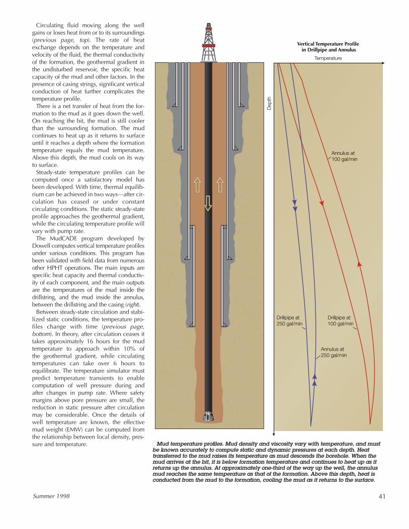
Circulating fluid moving along the wellgains or loses heat from or to its surroundings(previous page, top). The rate of heatexchange depends on the temperature andvelocity of the fluid, the thermal conductivityof the formation, the geothermal gradient inthe undisturbed reservoir, the specific heatcapacity of the mud and other factors. In thepresence of casing strings, significant verticalconduction of heat further complicates thetemperature profile.
There is a net transfer of heat from the for-mation to the mud as it goes down the well.On reaching the bit, the mud is still coolerthan the surrounding formation. The mudcontinues to heat up as it returns to surfaceuntil it reaches a depth where the formationtemperature equals the mud temperature.Above this depth, the mud cools on its wayto surface.
Steady-state temperature profiles can becomputed once a satisfactory model hasbeen developed. With time, thermal equilib-rium can be achieved in two ways—after cir-culation has ceased or under constantcirculating conditions. The static steady-stateprofile approaches the geothermal gradient,while the circulating temperature profile willvary with pump rate.
The MudCADE program developed byDowell computes vertical temperature profilesunder various conditions. This program hasbeen validated with field data from numerousother HPHT operations. The main inputs arespecific heat capacity and thermal conductiv-ity of each component, and the main outputsare the temperatures of the mud inside thedrillstring, and the mud inside the annulus,between the drillstring and the casing (right).
Between steady-state circulation and stabi-lized static conditions, the temperature pro-files change with time (previous page,bottom). In theory, after circulation ceases ittakes approximately 16 hours for the mudtemperature to approach within 10% of the geothermal gradient, while circulatingtemperatures can take over 6 hours toequilibrate. The temperature simulator mustpredict temperature transients to enablecomputation of well pressure during andafter changes in pump rate. Where safetymargins above pore pressure are small, thereduction in static pressure after circulationmay be considerable. Once the details ofwell temperature are known, the effectivemud weight (EMW) can be computed fromthe relationship between local density, pres-sure and temperature.
Temperature
Vertical Temperature Profile in Drillpipe and Annulus
Dep
th
Annulus at100 gal/min
Drillpipe at250 gal/min
Drillpipe at100 gal/min
Annulus at250 gal/min
■Mud temperature profiles. Mud density and viscosity vary with temperature, and mustbe known accurately to compute static and dynamic pressures at each depth. Heattransferred to the mud raises its temperature as mud descends the borehole. When themud arrives at the bit, it is below formation temperature and continues to heat up as itreturns up the annulus. At approximately one-third of the way up the well, the annulusmud reaches the same temperature as that of the formation. Above this depth, heat isconducted from the mud to the formation, cooling the mud as it returns to the surface.
42 Oilfield Review
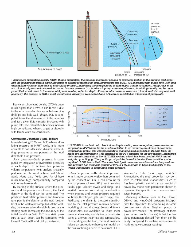
Equivalent circulating density (ECD) is oftenmuch higher than EMW in HPHT wells dueto the small annular clearances between thedrillpipe and hole wall (above). ECD is com-puted from the dimensions of the annulusand, for a given fluid viscosity, increases withpump rate. The calculation becomes increas-ingly complicated when changes of viscositywith temperature are considered.
Computing Downhole Fluid PressureInstead of using EMW and ECD when calcu-lating pressure in HPHT wells, it is moreaccurate to consider static, dynamic and cut-tings pressures as components of the totaldownhole fluid pressure.
Static pressure—Static pressure is com-puted by integration of hydrostatic pressuresat each depth. To achieve this, pressure-volume-temperature (PVT) analysis is usuallyperformed on the mud or base fluid (aboveright). Many base fluids used for oil-basemuds have high compressibility comparedwith water-base muds.
By starting at the surface where the pres-sure and temperature are known, the localdensity of the fluid can be computed. Thepredicted hydrostatic pressure and tempera-ture permit the density at the next deeperlevel in the well to be computed. At the well-site, the measured mud weight is used as thestarting point, increasing the accuracy of theinitial conditions. With PVT data, static pres-sure at each depth can be computed withDowell MudCADE and DSHyd software.
Dynamic pressure—The dynamic pressureterm is more comprehensive than permittedby the concept of ECD. It can account forannular pressure losses (APL) due to movingfluids, pipe velocity (swab and surge) andinertial pressure from string accelerationwhen tripping and excess pressure requiredto break thixotropic gels (next page, top).Predicting the dynamic pressure contribu-tion to the total pressure requires accuratemodeling of mud rheology. Several differentrelationships are available to relate shearstress to shear rate, and define dynamic vis-cosity at a given shear rate and temperature.
Depending on the fluid, the mud engineerselects an appropriate rheological model onthe basis of fitting a curve to data from HPHT
viscometer tests (next page, middle).Alternatively, the mud properties may con-form to established relationships, such asBingham plastic model or an empiricalpower law model with parameters chosen torepresent the specific mud behavior (nextpage, bottom).
Modeling software such as the DowellDSHyd and MudCADE programs incorpo-rates the algorithms for computing dynamicpressure from either Bingham plastic orpower law models. The advantage of these(over more complex models) is that the rhe-ology parameters derived from them can beeasily compared to wellsite measurementsmade using viscometer readings.
Depth
Pressure
Circulatingpressures
Fracturepressure
Equivalentcirculating
pressure
Staticpressure
Increasing pump rate
Annularpressureloss tosurface
Annular pressure lossesStatic
pressure at TDCirculatingpressure at TD
■Equivalent circulating density (ECD). During circulation, the pressure increment needed to overcome friction in the annulus and circu-late the drilling fluid from a particular depth to surface represents an annular pressure loss (APL). APL increases with pump rate (left), anddrilling fluid viscosity, and adds to hydrostatic pressure, increasing the total pressure at total depth during circulation. Pump rates mustnot allow mud pressure to exceed formation fracture pressure (right). At each pump rate an equivalent circulating density can be com-puted that would result in the same total pressure at a particular depth. Since annular pressure losses are a function of viscosity and wellgeometry, the concept of ECD is most useful when viscosity is well-defined and APL can be modeled as a function of pump rate.
0.9
0.8
0.7
0.6
0.5
Spe
cific
gra
vity
Pressure, MPa
T = 17.2˚C
T = 100˚C
T = 140˚C
T = 170˚C
T = 205˚C
0 20 40 60 80 100 120
■ULTIDRILL base fluid data. Prediction of hydrostatic pressure requires pressure-volume-temperature (PVT) data for the mud in addition to an accurate simulation of downholetemperature profile. The compressibility of a drilling fluid depends on its base fluid; thesolids are incompressible. This example is the PVT diagram for the low-toxicity, biodegrad-able organic base fluid of the ULTIDRILL system, which has been used at 395°F and atweights up to 19 ppg. The specific gravity of the base fluid under these conditions at adepth of 16,000 feet, is 0.68. The same fluid (gold arrow) returned to surface temperatureand pressure has a specific gravity of 0.79, a 14% decrease in base fluid density at TD,which is important in computing static pressure.
Summer 1998 43
Cuttings pressure—An additional compo-nent of the total pressure is from cuttingsaccumulation, known as the cuttings pres-sure. Although high-density muds used inHPHT wells tend to reduce cuttings accu-mulation, their contribution to total mudpressure cannot be ignored. As cuttings aremore dense than mud, any accumulation ofcuttings in the wellbore will increase themud pressure acting on the borehole. Theadditional pressure from cuttings is affectedby rate of penetration (ROP), pump rate, cut-tings size and distribution.
High ROP increases accumulation of cut-tings, and creates large cuttings, which havea higher settling velocity. Although boththese effects can be reduced by increasingpump rate, they increase dynamic circulat-ing pressure at the bit. Therefore, duringdrilling there is a limit to how much thedynamic pressure can be reduced beforebenefits are overcome by increased cuttingspressure. When cuttings pressure becomessignificant at maximum pump rates, it can becontrolled by reducing ROP.
∆Phydrostatic
(b) (c)(a)
∆Pdynamic +∆Phydrostatic
∆PAPL +∆Phydrostatic
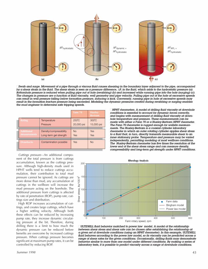
■Swab and surge. Movement of a pipe through a viscous fluid causes shearing in the boundary layer adjacent to the pipe, accompaniedby a shear strain in the fluid. The shear strain is seen as a pressure difference, ∆P, in the fluid, which adds to the hydrostatic pressure (a).Bottomhole pressure is reduced when pulling pipe out of hole (swabbing) (b) and increased while running pipe into the hole (surging) (c).The changes in pressure are a function of fluid viscosity, well geometry and pipe velocity. Pulling pipe out of the hole at excessive speedscan result in well pressure falling below formation pressure, inducing a kick. Conversely, running pipe in hole at excessive speeds mayresult in the formation fracture pressure being exceeded. Modeling the dynamic pressures created during swabbing or surging enablesthe mud engineer to determine safe tripping speeds.
250˚C
20,000 psi
Temperature
Pressure
Rating
Fann 70
300˚C
15,000 psi
No
Yes
Density/compressibility
Long-term gel strength
Additionalmeasurements
Yes
Yes
YesContamination possibleDrawbacks No
Huxley-Bertram
■HPHT rheometers. A model of drilling fluid viscosity at downholeconditions is essential to account for dynamic forces correctly,and begins with measurement of drilling fluid viscosity at down-hole temperature and pressure. These measurements can bemade with either a Fann 70 or a Huxley-Bertram HPHT rheometer.The Fann 70 rheometer is rugged enough for wellsite measure-ments. The Huxley-Bertram is a coaxial cylinder laboratoryrheometer in which an outer rotating cylinder applies shear stressto a fluid that, in turn, directly transmits measurable shear to aninner stationary probe. Temperature and pressure may be variedindependently, permitting modeling of most wellbore conditions.The Huxley-Bertram rheometer has five times the resolution at thelower end of the shear stress range and can measure density,compressibility and long-term gel strength under HPHT conditions.
200
150
100
50
00 100 200 300 400 500 600
Fann rotary speed, rpm
Rheology Analysis
She
ar s
tres
s, lb
f/100
ft2
Fann dataBingham modelPower law model
■ULTIDRILL fluid behavior matched to power law model. A model of the relationshipbetween shear stress and shear rate can be chosen after establishing the relationship at a given set of downhole conditions (using an HPHT rheometer). In this example, ULTIDRILLfluid behaves according to the power law model, so its viscosity can be predicted across arange of shear rates for the given conditions. Occasionally, drilling fluids may demonstratebehavior similar to more than one model under different conditions. By making a series oflaboratory tests, it is possible to predict viscosity across a range of downhole conditions.
44 Oilfield Review
Total pressure—The total pressure is thesum of static, dynamic and cuttings pressure.Expressing the downhole pressure in thisgeneral form covers all phases of the opera-tion. The total pressure can be balancedbetween the lowest safe static pressure andthe highest acceptable circulating pressureby achieving a compatible balance of thedifferent terms. The lowest pressures areachieved while accelerating the pipe duringpulling out of hole (swabbing) after circulat-ing bottoms up. The highest pressures occurwhile drilling with high pump and penetra-tion rates, while breaking circulation orwhile the pipe is accelerating during runningin through gelled fluid.
During drilling, mud properties may varywith time to such an extent that the rheologi-cal model might need to be changed.Temporary variations in mud properties cancause the same fluid to behave as a power lawfluid at one time and as a Bingham plasticfluid at another time, even in the same holesection. The ability to compare actual behav-
ior to both models at the wellsite, and toselect the appropriate one, is of great benefitin accurately predicting APL. In practice, theDSHyd program routinely achieves averagedifferences of less than 2% between predictedand measured standpipe pressures (above).
Pressure Control Drillers try to avoid fracturing the formation,but at critical depths the difference betweenthe pore pressure and the fracture pressure—mud pressure margin—is very small in somewells, on the order of 500 psi [3.4 MPa]. Iftotal pressure approaches fracture pressure,the first option is to reduce the dynamic pres-sure. Control of downhole pressure withinthe mud pressure window can be achieved inmany ways. Viscosity, mud weight, mudsolids content, pump rate and ROP can bemanipulated to change the various terms inthe total pressure expression.
Updated pressure predictions, based onwellsite measurements, can aid in decidingwhich parameters need to be changed to
retain the desired downhole fluid properties.Reducing pump rate or mud viscosity whilemaintaining the pump rate high enough toclean the hole and prevent excessive cut-tings pressure can help. The objective is tofind a pump rate that minimizes the contri-butions from dynamic and cuttings pressure.
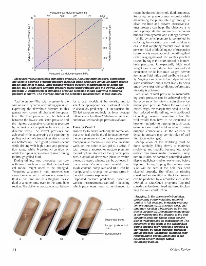
While dynamic pressure is controlled byreducing the viscosity, care must be taken toensure that weighting material stays in sus-pension. Mud solids falling out of suspensioncause density segregation of the drilling fluidcalled sagging (below). The greatest problemcaused by sag is the poor control of bottom-hole pressures. Unexpectedly high mudweight can cause induced fractures and lostcirculation while low mud weight permitsformation fluid influx and wellbore instabil-ity. Sagging can occur in both dynamic andstatic conditions but is most likely to occurunder low shear-rate conditions before staticviscosity is achieved.
Reduction of total pressure by manipulat-ing static pressure can be achieved only atthe expense of the safety margin above for-mation pore pressure. When the well is at acritical stage, this margin may need to be fur-ther reduced while drilling, with additionalcirculating pressure preventing influx. Thewell would then have to be circulated toheavier mud prior to tripping. In such cases,extreme care must be taken when makingdrillpipe connections, as the absence ofdynamic pressure may permit influx of wellfluid (connection gas).
Manipulation of the drillstring must bedone carefully, lifting slowly to minimizeswabbing, and steadily, because low accel-eration minimizes inertial pressures. Pumprate must also be carefully controlled whendisplacing lighter mud to heavier mud beforetripping. During tripping the cuttings pres-sure will be zero if the hole has beencleaned properly. The effects of trippingspeed and acceleration on the total pressurecan be predicted by a simulator such as theDSHyd or MudCADE programs. Optimalspeeds can be determined and used in plan-ning the well construction.
Measured standpipe pressure, MPa
Measured standpipe pressure, psi
Pre
dict
ed s
tand
pipe
pre
ssur
e, M
Pa
Pre
dict
ed s
tand
pipe
pre
ssur
e, p
si
10
8
6
4
2
0
1450
1160
870
580
290
00 2 4 6 8 10
0 290 580 870 1160 1450
■Measured versus predicted standpipe pressure. Accurate mathematical expressionsare used to describe dynamic pressure losses in fluids described by the Bingham plasticmodel and other models. After making wellsite viscosity measurements to define themodel, mud engineers compute pressure losses using software like the Dowell DSHydprogram. A comparison of standpipe pressure predicted in this way with measured pressure is shown. The average error in the predicted measurement is less than 2%.
Low-density fluid
(a) (b) (c) (d)
Suspended barite
Sagged (sedimented)barite
Slumped barite
■Sagging. In the absence of circulation,gravity may cause weighting material(barite) to fall, resulting in density segrega-tion or sagging (a). In deviated wells, sag-ging may result in a barite bed on the lowside of the hole (b). Depending on the angleof the wellbore and the strength of the bed,the barite beds can slump down the lowside of wellbores like an avalanche (c). Themovement of the solids in the drilling fluidduring sagging may result in a lowering ofthe viscosity by shear thinning, accelerat-ing the process. Ultimately, slumping mayresult in barite accumulation and a pro-nounced density change within the drilling fluid (d).

Summer 1998 45
Choosing Oil- or Water-Base MudThe decision to drill with oil- or water-basemud is likely to be made before detailedanalysis of the mud properties is attempted.Water-base muds (WBM) include conven-tional bentonite muds and polymer systems,while oil-base mud can be an invert emul-sion, all-oil system, or synthetic oil-base.Each has advantages in cost, environmentalimpact and drilling performance.
The stability—as defined by rheology and fluid-loss control—of oil-base muds athigh temperatures is a clear advantage in HPHT wells. Most are stable to at least450°F [230°C] in 16-hour laboratory tests.However, oil-base muds do have some sig-nificant disadvantages under HPHT condi-tions. Possibly the greatest of these is thesolubility of gas in the base fluid, whichmakes kick detection more difficult. A gasinflux while drilling will go into solution andremain there without causing a significantincrease in mud volume until it is relativelynear the surface. On coming out of solution,the gas rapidly increases in volume, requir-ing quick reactions to control the well. Also,the thermal expansion of oil-base muds ishigher than water-base muds, which canlead to pressurization of the annulus.
The conventional advantages and disad-vantages of oil-base mud also apply to HPHTwells: good protection against differentialsticking, reservoir protection and wellborestability in shales, claystones and salt.ULTIDRILL synthetic oil-base mud isbiodegradable and has low toxicity, reducingthe potential for environmental damage dur-ing its use. It has been successfully used attemperatures up to 395°F [202°C].
Optimizing HPHT Drilling Careful engineering and monitoring areneeded to reconcile the demands made ofmud systems (above right). Procedures forusing the mud must be consistent withpractical tripping speeds while ensuringpreservation of safety margins under allconditions.
Mud engineering—Consideration must begiven to maintaining the drilling fluid ingood condition through efficient solids con-trol, minimization of dilution requirementsand the reduction of fluid retention by cut-tings (right). Although many criteria must beconsidered when designing HPHT drilling
Drilling Fluid Property Required Performance in HPHT Wells
Plastic viscosity As low as reasonably possible to minimize ECD
Yield stress and gels Sufficient to prevent sag, but not so high as tocause gelation, or high surge and swab pressures
HPHT fluid loss As low as reasonably possible to prevent formationdamage and risk of differential sticking
HPHT rheology Predictable in order to control sag, gelation and ECD
Stability tocontaminants
Stable in the presence of gas, brine and cement
Gas solubility Needed for accurate kick detection and modeling
Stability to aging Properties do not change over time under eitherstatic or dynamic conditions
Solids tolerance Properties insensitive to drilling solids
Weighting Must be able to be weighted up rapidly if a kickis taken
Compressibility Must be known to estimate downhole pressuresand ECD
■Key drilling fluidproperties. Mudengineers mustconsider manyaspects of mudperformancewhen designingan HPHT drillingfluid system. Thetable shows theeffect of severalkey drilling fluidproperties on mudperformance.
High pump rate
Low pump rate Low mud weight
High mud weight
Differential sticking minimizedHigh rate of penetration
Good hole stability;washouts minimized
Low conditioning requirements
Low ECD and risk of fracture
Increased hydraulichorsepower at bit
Sagging minimized
Good hole cleaning
Maximum kick prevention
Fluid behavior
Hig
h vi
scos
ityan
d ge
lLo
wvi
scos
ity a
nd g
el
1
2
2
3
3
4
4
5
5
6
6
7
7
8
8
9
9
1
■Optimizing drilling fluid properties. Three mainvariables can be manipulated to achieve satisfac-tory drilling fluid performance: viscosity, mudweight and pump rate. The illustration shows howdifferent optimizations of these variables lead to different properties of the drilling fluid system. For example, a low risk of fracture (low ECD) isachieved with low mud weight, low viscosity andgel concentration, and low pump rate.

46 Oilfield Review
fluid, often one desirable property will beachieved only at the expense of another. Tosolve this problem, Dowell has developed amethod to optimize formulation propertiesuntil all criteria can be met to the satisfac-tion of the mud engineer (above).
Weighting up—Once the base fluid hasbeen selected, PVT data provide the basis forlocal density modeling. The static pressurewill already have been computed so as toexceed formation pore pressure by a mini-mum safety margin at all depths. Althoughthis seems straightforward, variations in muddensity due to temperature and pressuremust be considered in determining the staticpressure. Further complications may beencountered offshore where the minimumstatic pressure is required to overcome pore
pressure when the marine riser is discon-nected. The “riser margin” is a safety marginneeded when moving off a well in an emer-gency, and increases the minimum dynamicpressures used while drilling—especially indeep water where the additional pressurewith the riser connected is high.
Weighting material is chosen to achieve therequired mud weight based on offset wellpressures and factors such as sag and gellingbehavior of the mud. Barite, milled toachieve desired particle size (typically lessthan 75 �m), is a common weighting agent.6
High-quality barite is essential for HPHT mudbecause impurities or poor particle size dis-tribution may result in problems that are mag-nified in the HPHT environment (below left).The presence of clay impurities in barite canresult in gelation at 275°F [135°C] as theclays “burn out.” Carbonate and iron miner-als also cause changes in the mud as theirsolubility with changing mud temperaturecauses flocculation. Other chemical residueslead to severe foaming problems at high tem-perature. Sagging problems can be reducedby specifying ultrafine particle size (less than15 �m).
In high-density mud systems, barite canaccount for up to 78% by mass and up to45% by volume. When high mud weightsare required, the solids ratio may reach apoint where the mud becomes susceptible togelling in the event of fluid loss. The solidsratio can be reduced by using high-densityweighting agents such as hematite. In anycase, the mud engineer routinely measuressolids content and fluid loss during mudchecks to ensure they do not exceed designparameters during drilling.
Problematic gels—Gels and high-viscosityfluids have considerable effects on the mudpressure acting on the formation when trip-ping in or out of the hole. They are controlledby varying the appropriate mud additives toprevent excessive gelation while ensuringthat weighting agents stay in suspension. Ifthe gel strength and viscosity can be deter-
mined at downhole conditions, their effectson dynamic pressure can be simulated.When influx cannot be prevented by restrict-ing tripping speed and acceleration, specialprocedures are needed to permit operationsto continue. The simplest procedure is toincrease the mud weight before pulling out,but other techniques are possible.
If the predicted swab pressure is greaterthan the trip margin, the pumps can be oper-ated while tripping out. The additionaldynamic pressure resulting from maintainingcirculation can be made sufficient to achievethe desired margin above pore pressure.Alternatively, a heavy-weight slug can bespotted to minimize the risk of a kick. Withcareful design of both the volume andweight of the slug, a hydrostatic pressureprofile is achieved that avoids fracturing theformation while maintaining the desiredoverbalance for tripping.
Excessive swabbing is not the only problemassociated with high gel strength. The pres-sure increment needed to “break” (initiate)circulation in the presence of gels can bemuch higher than circulating pressures. Inthe worst case, the formation fracture pres-sure can be reached before the gel is broken.Gel strength needs to be sufficient to supportthe heavy particles in the mud but no more,otherwise excessive pressures may beneeded to break the gel. The pressuresneeded to break circulation can be modeledat the design stage, and the implications of these additional dynamic pressuresaccounted for in the design.
Excessive gel strength can result in a furtherhazard—trapped pressure (next page, top).An influx of formation fluid below a gel willnot be observed as a flow at surface until thegel is broken, by which time a large influxmay have occurred, resulting in a rapidlydeteriorating well-control situation. The prob-lem is magnified by the ability of gas influx to
Holecleaning
Input parameters
Pumppressure
Baritesagging
ECD and bithydraulics
Othercriteria
no no no no no
yes yes yes yesyes
Achievable? Achievable? Tolerable? Achievable? All met?Optimum
designparameters
Modify parameters
■Dowell muddesign flow chart.Dowell has devel-oped a standardprocedure to opti-mize mud rheologyand hydraulics.Starting with holecleaning perfor-mance, a range ofproperties of theproposed mud arechecked by model-ing. Parameterchanges are madeas required until theproperties and per-formance of the pro-posed mud systemmeet specifications.
Barite sample
Specific gravitySurface area, m2/g
Results in standard bentonite WBM after hotrolling 16 hours at 400˚F
PV, cpYP, lbf/100ft2
API fluid loss, mLSuspensionproperties
A
4.251.3
B
4.231.1
C
4.274.1
D
4.221.7
E
4.300.4
311611.5
VG
34 4 6.0
P
342014.0
VG
38 011.5
G
34 0 2.5
G
■Effects of barite quality. Susceptibility to sagging in a drilling fluid is greatlyaffected by the particle size of the weight-ing material. The smaller the particle size,the slower the speed with which it fallsthrough a static fluid, and static sag is less likely to occur. The effects of baritequality are summarized in the table,which shows the plastic viscosity (PV),yield point (YP), API fluid loss and quali-tative particle suspension of a water-basebentonite mud recipe made up with fivedifferent barite samples. Suspensionproperties have been rated as follows: VG = very good, G = good, P = poor. Thebarite particle size is reflected by the sur-face area (m2/g). The smaller the particles,the greater their surface area per gram, so the finer barite has a larger surface area (as in sample C).

Summer 1998 47
cause gelling in water-base muds under cer-tain conditions. If the gas contains carbondioxide [CO2], the pH is reduced, causingdispersants to become less effective, and thecarbonate and bicarbonate ions in the mud tocontinue promoting gelation. Freshwater gelmuds with high solids contents are particu-larly susceptible to this effect. To minimizetrapped pressure, the gel content must bekept as low as practically possible.
Controlling mud density—Frequent checksof mud density are essential to maintainingdownhole pressures within the mud pressureoperating window. Recently a technique hasbeen developed to correct surface measure-ments of mud density for temperature effectsand has been used by Shell UK and Dowellin drilling Heron and Shearwater HPHT wellsin the UK sector of the North Sea.7 Thedrilling program for these wells specified thatthe overbalance should be limited to 200 psi[1.4 MPa]. Based on the conventional proce-dure for measuring the mud weight, the errorin mud-pressure gradient resulting from atemperature that was 5°F to 15°F [3°C to 8°C]different from the assumed temperature wasestimated at 1.5 pptf (psi per thousand ft) to4.5 pptf [0.0035 SG to 0.0104 SG]. With truevertical depths (TVD) in excess of 15,000feet, the errors in downhole pressure wereestimated at up to 67 psi [460 kPa], far greaterthan what was acceptable with such a small
planned overpressure. By modifying the pro-cedure for taking the mud sample tempera-ture during measurement of the mud weight,such errors have been largely eliminated.
Pump rates—Minimum pump rates toclean the well are usually low due to thebuoyancy of cuttings in high-density drillingfluids. Therefore, in vertical boreholes, holecleaning is not usually a big concern inHPHT wells, and pump rates in HPHT wellsare more likely to be decided by other fac-tors. Although low pump rates help maintainlow ECD, the well program may call forhigher rates to reduce bottom-up time andpermit timely analysis of drilled cuttingslithology, background or connection gas,and mud solids. It is good practice to design
for pump pressures below rig capacity toenable dynamic kill, the intentional increaseof dynamic pressure by increasing annularflow rates, to be used when attempting tocontrol the well.
Controlling sag—If hole cleaning is not aconcern, the mud engineer can focus onassessing the possibility and effects of sag-ging. Modeling sagging behavior is difficult,and is usually empirically assessed in labexperiments and minimized as far as possi-ble. Schlumberger Cambridge Research,Cambridge, England has conducted ambienttemperature and pressure experiments with adynamic sag tester from which guidelines onthe effects of the type of weighting agents,sag mechanisms and low-sag additives havebeen derived. Procedures written into wellprograms for mud conditioning, monitoringof mud weight and tripping can all help min-imize the effects of sagging.
At the wellsite, the amount of sag occurringin a mud can be quantified from the heaviestand the lightest components of the circulat-ing mud. After assessment of the amount ofsag of the circulating mud, appropriate pro-cedures are used to minimize it. In particu-lar, if changes in mud weight indicatedensity segregation is occurring, laminarshear at low pump rates (which promotessag) should be avoided (below). Similarly,circulation at low pump rates prior tocementing should be minimized.
Once sag behavior is defined, the hydraulicproperties of the mud formulation can beconsidered in the design process. The goal ofthe mud engineer is to design a mud that willcontinue to function between pore pressureand fracture pressure at all times. These pres-sure limits define the critical mud pressureoperating window and must include marginsto account for dynamic pressure resultingfrom swab and surge when tripping.
Dep
thPressure
Gel GelFluidinflux
Pressure
Gel
■Gel support of pressure differentials. Absence of movement within a drilling fluid canresult in the formation of gels, which act as weak elastic solids. When breaking circula-tion, some of the pressure beneath the gel will be taken by the pipe or borehole walls(left). This pressure could be high depending on the gel strength and can result in forma-tion fracture. In the case of an influx of formation fluid beneath a gel, the influx cannot bedetected unless the differential pressure is high enough to break the gel. A significantwell-control hazard exists when the gel is eventually broken down during circulation,resulting in a kick being taken (right).
Mud specific gravity
Dep
th, m
1.90
1000
2000
3000
4000
5000
6000
2.00 2.10 2.20 2.30 2.40 2.50 2.60
Losses
■Density segregation due tosagging. The graph shows thelocal mud weight recorded atthe end of recording a suite oflogs 67 hours after circulationin a North Sea HPHT well.After extensive sagging, theweighting medium slumped to4000 m and deeper. The mudspecific gravity was nominally2.15. However, after the den-sity segregation occurred, theminimum recorded was 1.89,and the maximum 2.45. Theincrease in local density nearTD resulted in wellbore insta-bility followed by losses,although the situation wascontrolled. [Adapted from Gib-son, Bergerot and Humphreys,reference 2.]
6. API specification for barite is that residue greater than75 �m is a maximum of 3.0% by weight.

48 Oilfield Review
Mud StabilityIn HPHT wells, the temperature stability ofthe mud is a key consideration in completingthe mud design. The degradation of mudproducts is temperature and time dependentand can affect all mud properties. Both oil-base and water-base muds can suffer fromhigh-temperature gelation, though the mech-anisms are different. Fluid loss increases withtemperature and is affected by both productdegradation and gelation. Finally, smallchanges in solids content that result fromfluid loss can have a significant impact onviscosity in the high-solids muds typical ofHPHT applications.
Temperature stability is tested by hot-rolling mud samples in the lab. Samples areplaced in pressure vessels known as bombsand heated to test temperature in an ovenwhile being continuously agitated by rolling.A cycle of temperatures and pressures withperiodic assessment of properties tests theability of a mud formulation to withstanddrilling conditions. In some cases, samplesmay be intentionally contaminated to test forpotential adverse interactions.
Quality control of raw materials is essentialif the drilling fluid is to behave as expected.Particle size is important in defining saggingand rheology, so it is critical that laboratorytests be carried out on representative sam-ples. Batch numbers and mixing proceduresensure that the mud that goes in the well isas close as possible to the proposed formula-tion and to that tested in the lab.
After establishing test results and optimiz-ing the drilling fluid, the formulation of thedrilling fluid can be recorded for mixing inbulk. In particularly sensitive conditions, theformulation includes batch numbers forproducts to permit traceability. Proceduresfor mixing and remixing the mud after agingaccompany the formulation to ensure con-sistent performance in the field.
Data logger for mud control—To monitormud continuously during HPHT operations,Dowell has developed a data logger calledthe FMP drilling fluids monitoring package(above). The FMP data logger records muddensity, temperature, rheology (yield pointand plastic viscosity at a given temperature)and, in water-base mud, pH typically at 10-minute intervals.
The mud data are analyzed by PRISM pre-cision recording for job supervising andmonitoring software, and presented as a logof fluid parameters against time. The abilityto see trends in these data is of great value incross-checking other measurements andalerting the crew to changing conditions. Forexample, the mud balances used on HPHTwells comprise matched components,which, if accidentally mixed between sets,could result in uncalibrated readings. Aninconsistent reading from such a balancecould be seen quickly, and corrective actiontaken immediately.
CementingAfter casing is set, the final step in constructinga new well is sealing the annulus betweenthe casing and borehole with cement. One ofthe objectives of the cementing design is toremove the mud from the annulus with aspacer and then to displace the spacerentirely with cement, leaving no channels orother flaws. To achieve this, the spacer and
cement are formulated with a hierarchy ofboth density and viscosity: the spacer shouldbe more viscous and more dense than themud it displaces, and the cement more vis-cous and dense than the spacer.
The normally preferred turbulent flow tech-nique for mud removal is impractical forHPHT applications due to the high viscosityand density of both spacer and cement. Flowrates in excess of 20 bbl/min [3.2 m3/min]would be needed to achieve turbulent flow. In practice only 3 to 5 bbl/min [0.48 to0.79 m3/min] is achievable, before thedynamic pressure generated would lead tothe bottomhole pressures exceeding theformation fracture pressure.
Modeling hydraulic flow during HPHTcementing is essential to achieve the highestpractical annular flow rates. Software, suchas the Dowell CemCADE program, simulatesthe job based on well geometry, reservoirpore and fracture pressures, fluid densitiesand rheology and casing strength. Severalcombinations of pump rate, fluid densitiesand rheology are modeled with manual iter-ation to find the widest possible pump raterange, the shortest time to complete the jobwith the best chance of mud removal.Temperatures after circulating and duringcementing are also computed by CemCADEsoftware for use in judging the slurry retarda-tion needed.
Spacer design becomes more challengingwith oil-base mud. The spacer must be com-patible with both the mud and cement whileremaining stable at high temperature, retain-ing high viscosity and preventing excessivefluid loss. Spacer and slurry must also becompatible with downhole elastomers. Oil-water emulsions, such as the Dowell MUD-PUSH-XEO spacer are being successfullyused to tackle these demands in HPHT wells.
Three rheology flow loops
Densitometer
FMP Drilling Fluids Monitoring Package
Airsupply
pH as read by FMP package, varying inversely with temperature
Plastic viscosity, cp
Yield point, lbf/100ft2
PRISM Output of Computed FMP Measurements
Inlet strainer pressure, psi
Temperature, ˚F, reducing due to pumps off, then cold mud in riser
690
680
670
660
650
640
100
90
80
70
60
50
40
30
20
10
0
140
120
100
80
60
50
40
30
20
10
0
12.0
11.8
11.6
11.4
11.2
11.0
10.8
(2)
(2)
(1)
(1)
(3)
(3)
(5)
(5)
(4)
(4)
0 am 2 am 4 am 6 amTime of day
8 am 10 am 0 am
Mud weight, pptf50
40
30
20
10
0
(6)
(6)
■FMP equipment. The FMPdrilling fluids monitoring pack-age is an online unit developedby Dowell for measurement ofdrilling fluid temperature, den-sity, rheology and pH of thewater-base mud (left). All mea-surements are sampled for anal-ysis using a PC running PRISMsoftware (right). The nonradioac-tive densitometer measures theresonant frequency of a U-tubecontaining mud. Rheology ismeasured by recording the pres-sure drop across three rheologyflow loops of different diametersat a constant flow rate. Observa-tion of trends and the interdepen-dence of parameters help distin-guish potentially hazardousconditions from normal varia-tions, which might not be possi-ble with infrequent sampling byhand. In the example shown,small variations in yield point(YP), plastic viscosity (PV) andpH have been caused by achange in mud temperature.Conventional sampling couldhave resulted in unnecessaryadjustment of mud parameters ifthe FMP data logger had notbeen available.
Summer 1998 49
Cement slurry design—Slurry design gener-ally consists of formulating cement additivesto give the desired density, fluid-loss control,rheology while pumping, the appropriatesetting time and adequate strength when set.Slurry properties must ensure solids stay insuspension, just as barite must be suspendedin mud. Failure to do so can result in loss ofwell control and channeling on the high sideof deviated holes. As cement particles settleto the low side, a continuous water channelmay form on the upper side of the hole, cre-ating a path for gas migration.8
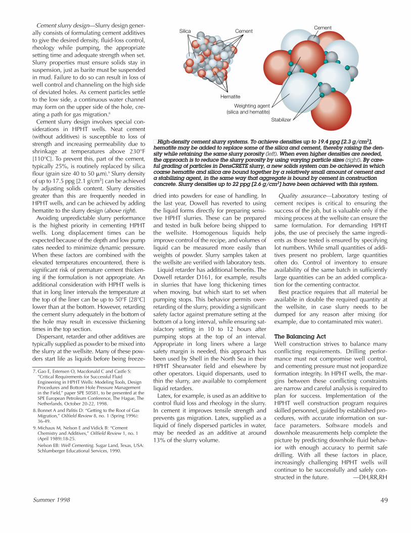
Cement slurry design involves special con-siderations in HPHT wells. Neat cement(without additives) is susceptible to loss ofstrength and increasing permeability due toshrinkage at temperatures above 230°F[110°C]. To prevent this, part of the cement,typically 25%, is routinely replaced by silicaflour (grain size 40 to 50 �m).9 Slurry densityof up to 17.5 ppg [2.1 g/cm3] can be achievedby adjusting solids content. Slurry densitiesgreater than this are frequently needed inHPHT wells, and can be achieved by addinghematite to the slurry design (above right).
Avoiding unpredictable slurry performanceis the highest priority in cementing HPHTwells. Long displacement times can beexpected because of the depth and low pumprates needed to minimize dynamic pressure.When these factors are combined with theelevated temperatures encountered, there issignificant risk of premature cement thicken-ing if the formulation is not appropriate. Anadditional consideration with HPHT wells isthat in long liner intervals the temperature atthe top of the liner can be up to 50°F [28°C]lower than at the bottom. However, retardingthe cement slurry adequately in the bottom ofthe hole may result in excessive thickeningtimes in the top section.
Dispersant, retarder and other additives aretypically supplied as powder to be mixed intothe slurry at the wellsite. Many of these pow-ders start life as liquids before being freeze-
dried into powders for ease of handling. Inthe last year, Dowell has reverted to using the liquid forms directly for preparing sensi-tive HPHT slurries. These can be preparedand tested in bulk before being shipped to the wellsite. Homogenous liquids helpimprove control of the recipe, and volumes ofliquid can be measured more easily thanweights of powder. Slurry samples taken atthe wellsite are verified with laboratory tests.
Liquid retarder has additional benefits. TheDowell retarder D161, for example, resultsin slurries that have long thickening timeswhen moving, but which start to set whenpumping stops. This behavior permits over-retarding of the slurry, providing a significantsafety factor against premature setting at thebottom of a long interval, while ensuring sat-isfactory setting in 10 to 12 hours afterpumping stops at the top of an interval.Appropriate in long liners where a largesafety margin is needed, this approach hasbeen used by Shell in the North Sea in theirHPHT Shearwater field and elsewhere byother operators. Liquid dispersants, used tothin the slurry, are available to complementliquid retarders.
Latex, for example, is used as an additive tocontrol fluid loss and rheology in the slurry.In cement it improves tensile strength andprevents gas migration. Latex, supplied as aliquid of finely dispersed particles in water,may be needed as an additive at around 13% of the slurry volume.
Quality assurance—Laboratory testing ofcement recipes is critical to ensuring thesuccess of the job, but is valuable only if themixing process at the wellsite can ensure thesame formulation. For demanding HPHTjobs, the use of precisely the same ingredi-ents as those tested is ensured by specifyinglot numbers. While small quantities of addi-tives present no problem, large quantitiesoften do. Control of inventory to ensureavailability of the same batch in sufficientlylarge quantities can be an added complica-tion for the cementing contractor.
Best practice requires that all material beavailable in double the required quantity atthe wellsite, in case slurry needs to bedumped for any reason after mixing (forexample, due to contaminated mix water).
The Balancing ActWell construction strives to balance manyconflicting requirements. Drilling perfor-mance must not compromise well control,and cementing pressure must not jeopardizeformation integrity. In HPHT wells, the mar-gins between these conflicting constraintsare narrow and careful analysis is required toplan for success. Implementation of theHPHT well construction program requiresskilled personnel, guided by established pro-cedures, with accurate information on sur-face parameters. Software models anddownhole measurements help complete thepicture by predicting downhole fluid behav-ior with enough accuracy to permit safedrilling. With all these factors in place,increasingly challenging HPHT wells willcontinue to be successfully and safely con-structed in the future. —DH,RR,RH
CementCement
Hematite
Weighting agent(silica and hematite)
Stabilizer
Silica
■High-density cement slurry systems. To achieve densities up to 19.4 ppg [2.3 g/cm3],hematite may be added to replace some of the silica and cement, thereby raising the den-sity while retaining the same slurry porosity (left). When even higher densities are needed,the approach is to reduce the slurry porosity by using varying particle sizes (right). By care-ful grading of particles in DensCRETE slurry, a new solids system can be achieved in whichcoarse hematite and silica are bound together by a relatively small amount of cement anda stabilizing agent, in the same way that aggregate is bound by cement in constructionconcrete. Slurry densities up to 22 ppg [2.6 g/cm3] have been achieved with this system.
7. Gao E, Estensen O, Macdonald C and Castle S:”Critical Requirements for Successful FluidEngineering in HPHT Wells: Modeling Tools, DesignProcedures and Bottom Hole Pressure Managementin the Field,” paper SPE 50581, to be presented at theSPE European Petroleum Conference, The Hague, TheNetherlands, October 20-22, 1998.
8. Bonnet A and Pafitis D: “Getting to the Root of GasMigration,” Oilfield Review 8, no. 1 (Spring 1996):36-49.
9. Michaux M, Nelson E and Vidick B: “CementChemistry and Additives,” Oilfield Review 1, no. 1(April 1989):18-25.Nelson EB: Well Cementing. Sugar Land, Texas, USA:Schlumberger Educational Services, 1990.