high-performance portable pcb inspection system vt-rns-pt · 2 software option simplified initial...
TRANSCRIPT

The Advanced Portable PCB Inspection System: Easier Operation and Superior Performance
High-performance Portable PCB Inspection System
VT-RNS-pt

2
Software option
Patent pendingSimplified Initial Program Creatione-iT (easy-image Teaching)
● Simply select a visual image and the Module Library function of e-iT helps in the setting of complex solder shapes.
● This dramatically speeds up the creation of inspection programs, both for beginners and for persons experienced in AOI operation.
PCB design
NEW
2. CAD mode uses CAD data in OMRON's standard format.
Note 1. The CTS (concurrent teaching system) is software for tuning or for creating initial programs. e-iT (easy-image Teaching) runs on CTS.
CTS
PCB dataPCB size, rail width
Library browserSelect several PCB colors or component colors from the choices.
Inspectiondata
Conversion dataComponent data
Coordinate data
Inspection standard, Color parametersModule library
(PCB-CAD)
CAD mode
Inspection program
Existing product
CAD system
CAD dataMounter data
e-iT
Inspection data creation technology
e-iT

3
Module LibraryThis library simplifies the parts that need the most know-how for beginners.
Simply select component creation, and the color parameters and inspection standards are automatically set. This lets you create initial programs quickly and easily.
Adjust the inspection standard and color parameter per
component type (variation).
Parameters to meet conditions are entered by simply selecting
the options including component color, solder shape and so on.
(CTS Screen) (Library browser screen)
Set the inspection standard and color parameter
Select component creation condition
From To

4
Highly Precise Inspection of Lead Floating in Mini-mold Components
Lead floating in mini-mold components can be more precisely
inspected by using a combination of color highlight illumination and
newly developed lead extraction logic.
OK product image
NG product image
NEW Patent pending
Character Inspection
Automatic binarization enables stable inspection even for characters that are distorted, blurred, thin, or thick. A block division system increases the number of image divisions so that it's possible to inspect in greater detail.
Note: Effective for polarity and flip inspection of mini molds.
Multi-block PCBs (e.g., Modules)
Block Units can be just a few millimeters in size (up to 1,200 block units).
TeachingInspection Tact Time
Several blockunits
1 field
High-speed inspections are achieved with no waste. Several block unit images are placed on one screen when the screen is rearranged.
Easily copy block unit data by specifying the number and pitch in each direction.

5
Mounting block unit PCBs
Status for inspection
Actual inspection
Land auto extraction
Block unit θ adjustment
Supports PCBs on Carrier Boards (Flexible PCBs)
Individual θ adjustment and inspection are possible for each block unit. And this function can be used together with OMRON's land auto-extraction technology for even greater precision.
Carrier board
Carrier board
Jig for loading
Inspection flow Flexible PCB Production
PCB θ adjustmentNote: Effective for inspections of PCBs on carrier boards.
Block unit PCBs
Pre-mounting Inspections of ICs and CSPs (Foreign Object Inspection)
Inspections can be performed for foreign objects in the component mounting field for IC and CSP pre-mounting inspection.
Note: Good models are registered in advance. This makes teaching easy.
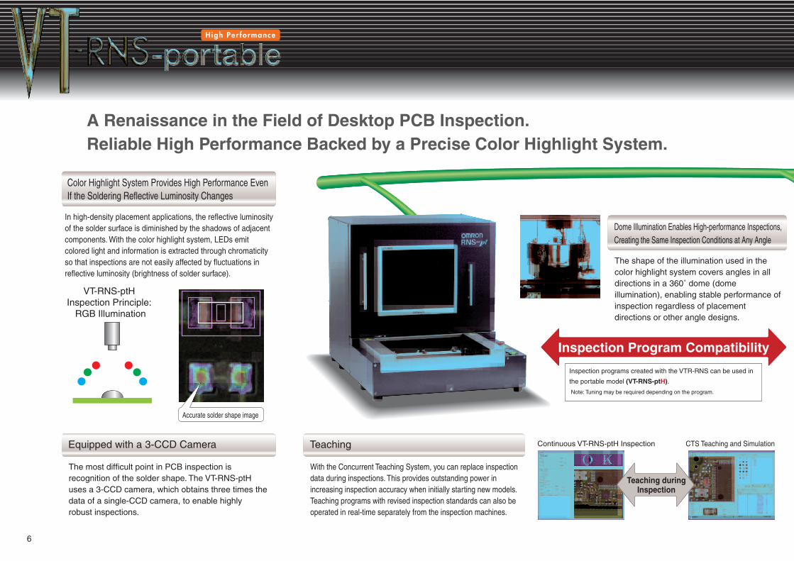
A Renaissance in the Field of Desktop PCB Inspection.Reliable High Performance Backed by a Precise Color Highlight System.
Teaching duringInspection
Inspection Program Compatibility
Continuous VT-RNS-ptH Inspection CTS Teaching and Simulation
Color Highlight System Provides High Performance Even If the Soldering Reflective Luminosity Changes
In high-density placement applications, the reflective luminosity of the solder surface is diminished by the shadows of adjacent components. With the color highlight system, LEDs emit colored light and information is extracted through chromaticity so that inspections are not easily affected by fluctuations in reflective luminosity (brightness of solder surface).
Equipped with a 3-CCD Camera
The most difficult point in PCB inspection is recognition of the solder shape. The VT-RNS-ptH uses a 3-CCD camera, which obtains three times the data of a single-CCD camera, to enable highly robust inspections.
Dome Illumination Enables High-performance Inspections, Creating the Same Inspection Conditions at Any Angle
The shape of the illumination used in the color highlight system covers angles in all directions in a 360˚ dome (dome illumination), enabling stable performance of inspection regardless of placement directions or other angle designs.
Teaching
With the Concurrent Teaching System, you can replace inspection data during inspections. This provides outstanding power in increasing inspection accuracy when initially starting new models.Teaching programs with revised inspection standards can also be operated in real-time separately from the inspection machines.
Accurate solder shape image
VT-RNS-ptH Inspection Principle:
RGB Illumination
Inspection programs created with the VTR-RNS can be used in
the portable model (VT-RNS-ptH).
Note: Tuning may be required depending on the program.
6
Color EnhancingWith lead-free solder, there are inconsistencies in the reflective luminosity of the surface of the solder. With the VT-RNS-ptH, LEDs emit colored light and information is extracted in the form of chromaticity, so no inconsistencies are caused in the reflective luminosity. Accordingly, stable inspection can be performed even for lead-free solder.
Auto TeachingThe components are extracted automatically based on model pattern data, and an initial teaching program is created.
Integrated User InterfaceA consistent user interface is used for all VT-RNS-ptH models.There is no longer a need to learn many different operations. This makes operation efficient even for operators handling the VT-RNS-ptH for a variety of different applications.
Logic CustomizationThe VT-RNS-ptH is equipped with a logic customization function supporting flexible application to future changes in placement trends, such as lead-free soldering or new component types.
Multi-languageDuring any operation, the display language can be switched between English, Chinese, Korean, and Japanese with one touch.
Concurrent Teaching System (CTS): In-line Teaching (Same for P, Z, S Models)
Real-time View Station Batch Checking (RSV-B: Batch Checking)
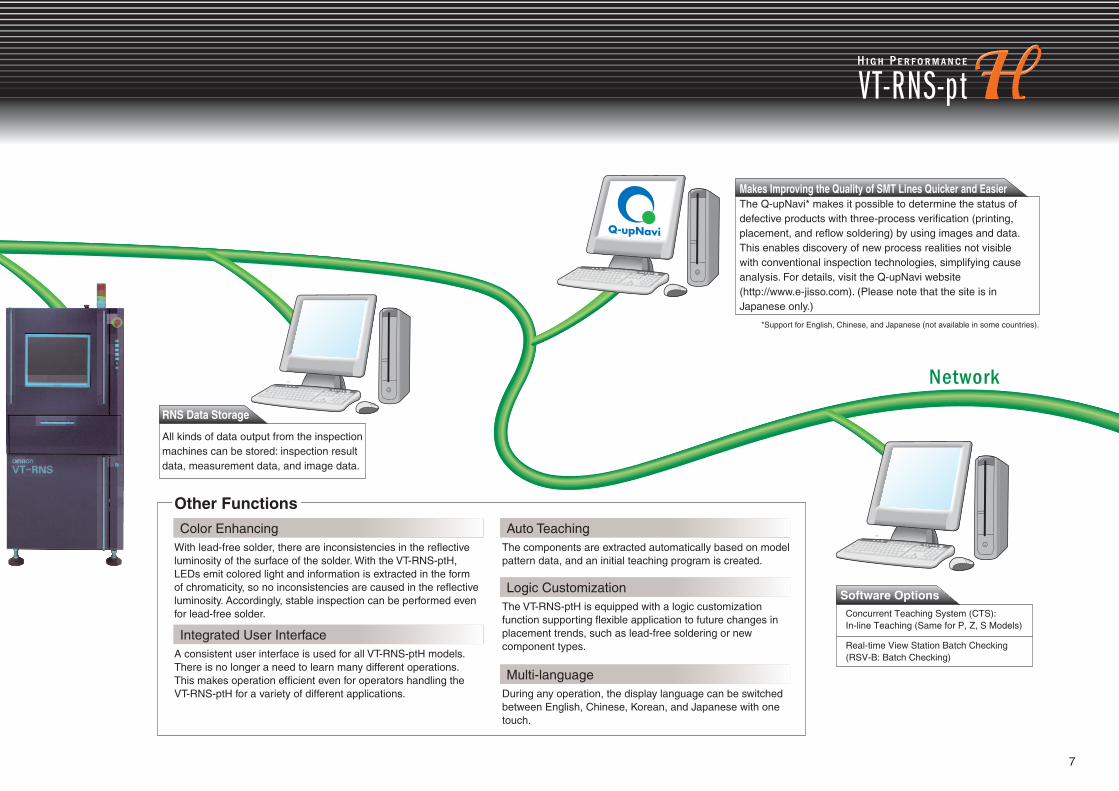
Makes Improving the Quality of SMT Lines Quicker and EasierThe Q-upNavi* makes it possible to determine the status of defective products with three-process verification (printing, placement, and reflow soldering) by using images and data. This enables discovery of new process realities not visible with conventional inspection technologies, simplifying cause analysis. For details, visit the Q-upNavi website (http://www.e-jisso.com). (Please note that the site is in Japanese only.)
*Support for English, Chinese, and Japanese (not available in some countries).
RNS Data Storage
All kinds of data output from the inspection machines can be stored: inspection result data, measurement data, and image data.
Software Options
Other Functions
7

Hardware Configuration Functional Specifications
Configuration and Specifications
Model
Type M size L size
Camera
Illumination
Image resolution
Main unit PCB carrier
width adjustment
PCB fixing method
Power supply
Ambient operating temperature 10 to 35˚C (50 to 95˚F)
Ambient operating humidity 35 to 80% (with no condensation)
Weight
Dimensions
Model VT-RNS-ptH
Type
Type Post-printing Post-placement Post-reflow
Dimensions
Thickness
Weight
Number of inspection points 40,000 lands/PCB max. 10,000 components/PCB max.
Data storage Computer hard disk
Component-specific inspection data library Component types, groups, variations
Inspection result output PCB name, PCB ID, component name, type of fault, PCB graphic, etc.
Communications Ethernet, RS-232C
Presence of solder, insufficient/excessive solder, solder shifting, grazing, bridging, spreading
Component shifting, polarity error, missing components, wrong components, solder balls, skewing, bridging, foreign objects
Presence of solder, wrong components, missing components, bridging, tombstones, lifting, component shifting, fillet, wettability, lead bending, adhesive, solder balls
Above PCB: 20 mm (0.79 in) (standard), 40 mm (1.57 in) (optional)Below PCB: 75 mm (2.95 in)
Image signal input unit
688 W × 905 D × 720 H mm(27.09 W × 35.63 D × 28.35 H in)
InspectablePCBs
Clearance
Inspection items
110 kg (242.5 lbs) max.
100 to 230 VAC ±10%,
single phase
100 to 240 VAC ±10%,
single phase
VT-RNS-ptH
3-CCD color camera
Ring-shaped LED (R, G, B)
10, 15, 20 µm
Manual
Outer frame
180 kg (396.8 lbs) max.
1,070 W × 1,458 D × 490 H mm(42.13 W × 57.40 D × 19.29 H in)
50 × 50 to 255 × 333 mm
(1.97 × 1.97 to 10.04 × 13.11 in)
0.3 to 2.5 mm (0.01 to 0.1 in)/0.3 to 3.0 mm (0.01 to 0.12 in)
1.0 kg (2.2 lbs) max./3.0 kg (6.6 lbs) max.
M size/L size
50 × 50 to 550 × 650 mm
(1.97 × 1.97 to 21.65 × 25.59 in)
Cat. No. Q307-E1-04 Printed in Japan1007-5M (0905) (H)
Authorized Distributor:
Note: Specifications subject to change without notice.
OMRON CorporationIndustrial Automation Company Sales & Marketing Division HQIT Solution DivisionSMT-Solution DepartmentSales Section No.1/No.2/No.3Engineering Group
1-11-1, Ohsaki, Shinagawa-ku, Tokyo,141-0032 JapanTel: Sales Section No.1: (81)-3-3779-9046No.2: (81)-52-561-0156No.3: (81)-6-6347-5830Engineering Group: (81)-3-3779-9046
OMRON INDUSTRIAL AUTOMATION (CHINA)CO., LTD.RM2211, Bank Of China TowerNo.200 Yin Cheng Road (M)Shanghai China 200120Tel: (86)-21-50372522/Fax: (86)-21-50372244
OMRON ASIA PACIFIC PTE. LTD.55 Ubi Avenue 1, #05-01Singapore 408935Tel: (65)-6547-6789/Fax: (65)-6547-6766
OMRON ELECTRONICS LTD.Opal Drive, Fox Milne, Milton KeynesMK15 0DG, UKTel: (44)-1908-258258/Fax: (44)-1908-258158
OMRON ELECTRONICS LLC1 East Commerce Drive, Schaumburg,IL 60173-5302, U.S.A.Tel: (1)847-843-7900/Fax: (1)847-843-7787
This document provides information mainly for selecting suitable models. Please read the Instruction Sheet carefully for information that the user must understand and accept before purchase, including information on warranty, limitations of liability, and precautions.
OMRON ELECTRONICS KOREA CO.,LTD.2F,Young Poong Bldg.,142,Nonhyeon-Dong,Gangnam-Gu,Seoul,135-749,KoreaTel: (82)-2519-3977/Fax: (82)-2519-3976