high-lift research for future transport aircraft · high-lift research for future transport...
TRANSCRIPT

HIGH-LIFT RESEARCH FOR FUTURE TRANSPORT AIRCRAFT
R. Radespiel, W. Heinze, L. Bertsch, Technische Universität Braunschweig, Hermann-Blenk-Str. 37, 38108 Braunschweig,
Germany
Abstract Careful analysis of long-term objectives of air transport indicates that the needed progress in vehicle perfor-mance cannot be achieved by following the current, evolutionary technology development. Particular exam-ples are noise reduction and high-lift performance at take-off and landing. The long-term objectives call for research on the fundamentals for a new segment of commercial low-noise transport aircraft with short take-off and landing capability, which allows a much better integration into the metropolitan areas of the industrial-ised society. Such research is in the focus of the Collaborative Research Centre CRC 880. The Centre aims at drastic reductions of airframe noise by developing the fundamentals of noise reducing surfaces in aero-acoustic and aerodynamic design. A promising approach towards reducing engine noise shields the noise by suited configuration design. Improving the efficiency of active high lift requires reducing the flow actuation power. For this objective the benefits of form-variable leading edges, by exploiting the synergies of suction and blowing in active high-lift flaps with spanwisely distributed compressor units, and finally the potentials of dynamic flow control are explored. The advances obtained in noise reductions and in effective high-lift tech-nologies are assessed using fully iterated aircraft designs. The Centre also seeks new knowledge on the dynamic behaviour of aircraft with active high lift during flight in the atmospheric boundary layer. Therefore, the flight mechanics of critical landing manoeuvers is analysed along with exploring the fundamentals of un-steady flow around active high-lift wings and the aero-elastic reactions of the wing structure on flight loads.
1. INTRODUCTION
The mobility needs of industrialized countries have gener-ated significant growth in aviation, bringing the air transport system closer to its limits. Aviation adds signifi-cantly to CO2 emissions, perceived noise and land usage of the developed industrial countries, and the used air-space has increased up to capacity limitations in some areas. These issues are reflected in the ‘‘Vision Flightpath 2050—Strategic Research and Innovation Agenda’’ [1]. According to these long-term objectives of the major Eu-ropean aviation stakeholders, new technological ap-proaches can only be successful if they address simulta-neously environment protection, drastic energy savings, improved flight safety, and reductions in door-to-door travel times.
A more detailed analysis of technologies for future com-mercial transport reveals the strong impact that the high-lift system of the aircraft has on the aircraft operating cost, the usage of carbon-based fuels, aircraft emissions, and flight safety. Multi-element high lift systems in use on present aircraft have a multitude of effects on aircraft performance. While their manufacture and maintenance affect aircraft operation cost, the capabilities of these systems to generate lift allow overall wing design for opti-mum cruise efficiency and enable aircraft service to a prescribed class of airport infrastructures. However, pre-sent high lift systems exhibit limited flexibility to extend their performance once wing sizing and detailed design of the leading edge and trailing edge devices for take-off and landing are completed. This leaves little design options to adapt high-lift performance later on, i.e. due to growing aircraft weight or for adapting to configuration changes. Furthermore, conventional leading edge devices such as slats or Kruger present a severe difficulty for introducing
laminar flow on the wing, as envisaged for significant cruise drag reductions. Finally, conventional high-lift de-vices are a major source of airframe noise of current air-craft. Note that the performance of the high-lift system also determines the air speed at take-off and approach conditions and affects all sources of airframe noise, as these sources scale with the 5th to 6th power of flow speed.
The Collaborative Research Centre CRC 880 located in Braunschweig, Germany, combines the competencies of Technische Universität Braunschweig, Universität Hanno-ver and the German Aerospace Center, DLR, for perform-ing fundamental and applied research in high lift of future commercial aircraft. The overall working hypothesis of the Research Centre states that active high-lift systems with high aerodynamic efficiency add significant value to future civil transport. These active systems can provide higher flexibility in the generation of high lift for aircraft families and aircraft upgrades, allow significant reductions of air-frame noise emissions, and finally provide a technically feasible and economically viable path towards short take-off and landing capabilities. The latter route of research aims at a new transport aircraft segment for operation on airports with shorter runway length presently not consid-ered in commercial air transport [2].
New aircraft of this segment would be equipped with ad-vanced technologies for drastic airframe and engine noise reduction. They would represent a community-friendly aircraft designed for operations much closer to the home of passengers than possible today, operating effectively in point-to-point services between metropolitan areas. The Research Centre CRC 880 has therefore devised a range of technology projects, aiming at drastic noise reductions and at the generation of efficient and flexible high lift. The

research also addresses flight dynamics of aircraft at take-off and landing. Technology assessment plays an integrated part in coordinating the Research Centre. For this purpose, the Centre defines reference aircraft config-urations using fully iterated preliminary aircraft designs. The reference configurations represent the state of the art in CO2 reductions, low noise, and STOL for efficient point-to-point service. The reference aircraft allow assessing the individual impact that the various research projects on aeroacoustics, aerodynamics, advanced wing materials and structures, and aircraft flight mechanics have. While detailed research objectives and the general layout of the CRC 880 research program were outlined in Ref. [3], recent technical progress within the three research areas of the Centre, i.e. aeroacoustics, efficient high lift, and flight dynamics was presented at the 2017 AIAA Aviation conference [4],[5],[6]. The present paper gives an overall status of the Centre’s technology advancements and knowledge gain, along with examples of assessing these advances on aircraft level.
2. REFERENCE CONFIGURATIONS FOR
TECHNOLOGY ASSESSMENT
The importance and possible benefits of research on noise reduction and high lift can only be assessed by taking its impact and complex interactions on overall air-craft level into account. The Research Centre CRC 880 therefore operates a central project on preliminary aircraft design with the goal of quantifying these effects. The central project supplies aircraft design requirements to the other research projects, thereby providing a suited frame-work for consistent simulations, experiments and analysis. The research projects, in return, provide geometry de-scriptions, power usage, noise sources and cost data for further use in technology assessments studies by the central project. This Chapter describes the aircraft design methods as used in the Research Centre, and character-izes the present reference configurations employed for technology assessment.
2.1. Aircraft design
2.1.1. Preliminary aircraft design using PrADO
The Research Centre uses the simulation tool Preliminary Aircraft Design and Optimisation, PrADO. PrADO simu-lates the iterative overall design process for a broad range of aircraft concepts [7]. The software core contains design and analysis modules, each of which provide a subtask of the overall design process. These modules mostly use physics-based models that are not restricted by the statis-tics of specific aircraft configurations. Examples of em-ployed fidelity are potential flow / boundary-layer models in aerodynamics and FEM for structure design and weight computation. The design iteration is completed, if im-portant calculated parameters show convergence. The modules communicate with each other through a data management system. This provides flexibility for adapting PrADO simulations to new design problems.
Aircraft with active high-lift systems show significant vis-cous interactions in lift and drag. PrADO models the spe-cial behaviour of wings with internally blown flaps by em-ploying a multiple-lifting-line method for 3D induced flow angles along with 2D RANS airfoil data to represent the
effect of blowing on airfoil lift and drag [8]. Lift increases due to propeller slipstream are taken into account by increments from RANS simulations as well. More recently, an extended aerodynamic model of active high-lift, propel-ler slipstream and all other aircraft components has been set up using the Panel Code VSAEROTM and automated geometry modules [9]. Aircraft system design for active high lift follows the system model of Koeppen [10]. The extended module calculates the masses and centre of gravity positions of the pipes, valves, and distribution elements including the necessary flow properties (flow mass rate, temperature and total pressure) at the engine bleed port in the case of a pure pneumatic Coanda sys-tem. PrADO also considers power generators attached to the aero engine that power electrically driven compres-sors as an alternative solution for providing compressed air to the high-lift flaps. These distributed systems are modelled following preliminary design studies of Ref. [11].
These system data are used for engine sizing and for the calculation of the engine off-design behaviour with or without operation of the internally blown flap system. For engine design and analysis, a thermodynamic engine model based on Mattingly [12] is available in PrADO. Further necessary data for propeller engine design, in-cluding the propeller size and mass, gear-box mass, and propeller efficiency factor, are taken from detailed NASA studies [13]. The design of reference aircraft with Ultra High Bypass Ratio Engine (UHBR) made detailed engine design studies necessary. These studies used extensive engine-cycle analyses [14] performed by a dedicated CRC 880 research project, and they resulted in well bal-anced design trades [15]. This provided the necessary input for the PrADO engine model using for the overall assessment tasks.
2.1.2. Robust optimisation
Reliable assessment of technology requires that incre-mental design changes should represent technological progress in a smooth and reliable manner. This is not achieved when the basic design is directly located on design boundaries or close to regions with steep gradients of the design object function. An incremental design change would then release snowball effects that introduce much larger design changes, thereby misleading engi-neering judgement on technology impact. Therefore, PrADO has been extended to allow numerical assessment of uncertain design data. The extension allows computa-tions of probabilistic density functions based on samples of deterministic aircraft design. This results in the need to provide a large number of designs, leading to massive computational efforts. For this purpose PrADO was inte-grated in a distributed component-based software system for the simulation of probabilistic models [16]. The system has multithreading and multitasking capability for distrib-uting the computational effort. The new probabilistic PrA-DO model with Monte Carlo sampling served to quantify the transmission of uncertain design parameters through the design process and to identify suited design parame-ters for robust aircraft design [16].
Optimising an aircraft configuration with both, a large number of uncertain aircraft parameters and a large num-ber of design parameters require extremely large numbers of model calls. Therefore, an efficient surrogate model is employed for robust aircraft optimisation. The present

surrogate model uses a variational framework, where least-square fits with multivariate polynomials approxi-mate the aircraft design data [17]. Typically, in the order of 1000 PrADO runs are needed to determine the weight factors of surrogate model basis functions.
Once the surrogate model is determined, the optimiser searches design solutions with minimum direct operation costs (DOC), while a number of design constraints must be satisfied. The constraints of importance concern the centre of gravity range, the runway length, and the al-lowed maximum lift coefficient during cruise to prevent buffeting. Present optimisations use seven design param-eters, i.e. wing area, wing aspect ratio, wing sweep angle, cruising altitude, cruising Mach number, engine bypass ratio for UHBR engines and overall pressure ratio. In total, 29 uncertain parameters in aircraft structure, aerodynam-ics, electrical systems, and aero engine are associated with prescribed uncertainty intervals, which were defined using expert knowledge. An optimum deterministic design provides an aircraft with minimal DOC at the middle point of the given uncertainty intervals, while a robust optimisa-tion finds the configuration with the minimum mean DOC of all probabilistic samples while all of these samples fulfil the design constraints.
2.1.3. Aircraft system noise prediction
Using overall aircraft design data as input, system noise predictions quantify the joint impact that technologies for efficient high-lift and for reducing flow noise have on noise on the ground. For this purpose, the Research Centre CRC 880 applies the Parametric Aircraft Noise Analysis Module PANAM of DLR [19]. PANAM runs integrated with PrADO, with all input provided by PrADO [20]. The noise prediction approach assumes that the overall aircraft noise emissions can be approximated as the sum of the most relevant, individual aircraft noise sources. The tool predicts ground noise using a suited propagation model, and accounts for aircraft-specific flight trajectories. PANAM employs physics-based, semi-empirical models for the relevant aircraft noise sources. These are airframe noise [21],[22], noise of propulsive jet [23] and fan noise [24]. The models include effects of relevant flow interac-tions between aircraft components. The shielding effects, for instance on engine fan noise, are considered using the DLR ray-tracing tool SHADOW [25],[26]. The rather short computation times of PANAM allow for direct integration into preliminary aircraft design studies.
As the Research Centre focuses on new high-lift technol-ogies for STOL aircraft, new or largely changed noise sources appeared. These sources are UHBR engine noise, propeller noise, and noise generated by high-lift flaps with active blowing. PANAM predicts propulsion noise using semi-empirical source models for jet and fan, respectively. It models jet noise originating from the core jet and bypass jet with Stone's model [23]. An updated model according to Heidmann [24] represents fan broad-band, discrete-tone, and combination-tone noise using an empirical database [19], which received a recent update for covering UHBR engines also. The analytical propeller noise model follows the parametric model of Hanson [27], valid for propellers in uniform inflow. Tractor propellers generate significant acoustic interactions with wing lead-ing edge and flaps. As PANAM presently has no physical-ly sound general model for these interactions, the current
predictions use scaled measured data from recent wind tunnel tests of a high-lift propeller-wing configuration [28]. A general noise model of active high-lift systems suitable for parametric noise prediction is unknown in the relevant literature. Hence, a parametric model requires numerical and experimental sensitivity studies of the noise sources involved. These studies are underway as part of the aero-acoustics research of the Centre. Until conclusive results of these studies are available, aircraft noise assessment must be based on suited assumptions. As described in Ref. [29] a Fowler flap model serves as an initial guess.
For evaluation and selection of promising aircraft con-cepts and technologies based on noise prediction results of parametric semi-empirical tools, it is essential to be aware of uncertainties associated with the underlying prediction process. Therefore, DLR has initiated uncer-tainty assessment of noise prediction for conventional transport aircraft [30]. Three sources of uncertainty are accounted for, i.e. the input data uncertainty, the noise modelling uncertainty, and the propagation uncertainty. A dedicated uncertainty module was implemented into PANAM to yield uncertainty intervals for predicted noise levels. Initial application is promising. The new tool identi-fies both, temporal and spatial distributions of uncertainty. This concept will be advanced to ultimately provide relia-ble uncertainties for the technologies and configurations as selected for the CRC 880.
2.2. CRC 880 reference configurations
The reference aircraft configurations used for technology assessment in CRC 880 represent the long-term vision of cruise-efficient low-noise transport with STOL capability. Top-down requirements are 2,000km range with 100 pas-sengers and 2,500kg freight. Details of economic as-sumptions are given in Ref. [17]. The aircraft mission requirements resulted in two basic layouts of reference aircraft. The first layout is a conventional turboprop air-craft. This choice is based on the assumption, that ad-vanced propellers yield very low operation cost and rea-sonably low noise emissions. This is the basis for configu-rations REF0 and REF2.
FIG 1. Turboprop reference aircraft REF2
While REF0 employs a trailing edge flap with internal blowing from engine bleed as the only high-lift device, the more advanced configuration REF2 adds a shape-adaptive droop nose, and distributed compressors located in the wing feed the active high-lift flap. This allows for sucking in the mass flow for internal flap blowing from a suited wing location, thereby improving the boundary layer behaviour of the upper wing surface. Both measures im-

prove maximum lift, increase significantly the stall angles and reduce the power extraction from the engines. There-fore, the turboprop engine needed to comply with 900 m runway is significantly smaller for REF2 compared REF0.
FIG 2. Variant REF0-CW of turboprop reference aircraft with channel wing for shielding propeller noise
FIG 1 displays the turboprop aircraft REF2, while TAB 1 documents important aircraft design parameters. REF2 represents the status of knowledge on efficient high lift, as obtained by CRC 880 at the end of the year 2014. The aircraft displayed in FIG. 2 is an intermediate configura-tion designed for shielding the propeller noise by the wing.
Therefore, the wing forms a partial channel, in which the propeller is embedded [31]. The channel leads to early wing stall at its centre line, for engine-out conditions. This explains the relatively low maximum lift coefficient of REF0-CW.
FIG 3. UHBR engine reference aircraft, REF3-BASIS
Moreover, the cruise configuration shows early onset of transonic flow in the channel [32], which limits cruise Mach number to values around 0.6, leading to rather high DOC due a loss of transport performance. The Centre concluded that the Channel Wing is a design option for aircraft with very short flight ranges only.
aBLC system off, bflaps in landing configuration; (..) with propeller effects, caccording to cruise conditions, daccording to EASA CS-25/FAR 25, sea level & wet runway, esafety factor 1.429, fengines, nacelles & pylons, gdesign mission, hcalculated for 14 operation years
TAB 1. Aircraft design data of reference aircraft of CRC 880

FIG 3 displays an alternate configuration that CRC 880 investigates in its search for design solutions with STOL capability, low noise and efficient cruise. The configuration employs UHBR-engines for large static thrust, low fuel consumption and flexibility in cruise Mach number. It has the engine over the wing’s trailing edge, for reducing cruise wave drag [33] and for shielding engine fan noise. This configuration has three different variants, according to TAB 1. The first design, REF3-BASIS, is the result of the deterministic PrADO code without accounting for un-certainties. It has a prescribed Mach number of 0.78, leading to a swept-back wing. It is heavier than REF2, due to its wing sweep, its unfavourable pylon geometry, and the higher resulting engine mass. This leads to aircraft growth and consequently, DOC of REF3-BASIS are al-most 5% higher than of REF2. REF3-BASIS provides the geometry for current aerodynamic and acoustic research, see Chapter 3.1. The second design allowed the flight Mach number to vary, while prescribing the runway length of 900m. The design process ended up with a lower Mach number and a non-swept wing, resulting in lower DOC. This is the result of the adverse effects of wing sweep on high-lift performance and weight, which must be compen-sated by a larger engine. The third design accounts for uncertainties, as described in Chapter 2.1.2.
The results of PrADO designs yield important insight into design sensitivities, as FIG 4 shows. PrADO identifies a significant effect of the prescribed runway length on most of the aircraft design parameters, for runway lengths be-low 1200m. Designs with uncertainty have a larger wing with a lower wing sweep for short runways. The results of direct operation cost, DOC, display deterministic designs without uncertainties close to the lower left boundary of the cloud of valid PrADO solutions, yielding a safety mar-gin to fulfil the design requirements even with significant uncertainties.
FIG 4. Effect of runway length on UHBR aircraft design parameters and resulting DOC with and without uncertain-ties
3. CRC 880 RESEARCH AREAS
The research of the CRC 880 aims at drastic reductions of aircraft noise, at a new level of flexibility in providing the aircraft with high lift coefficients for take-off and landing, and at new knowledge on the dynamics of commercial transport with STOL capabilities. These objectives lead to three research areas of CRC 880. This chapter outlines the logic of defining the research directions within these areas and describes important research results.
3.1. Fundamentals of Low Noise Take-Off and
Landing
While reduced flight speeds at take-off and landing gen-erally open way to reduced airframe noise, active high-lift systems and configurations designed for utilizing high-lift coefficients bear the risk of new sources dominating the overall noise. These are noise from the interaction of local high-velocity air streams with trailing edges and propul-sion noise. The Research Centre therefore pursues two fundamental approaches for noise reduction, as FIG. 5 shows. These are reductions of the sources of airframe noise by tailored porous surface materials and reduction of propulsion sound radiation by configuration design [4].
FIG 5. Overview of research in aeroacoustics
The first objective of reductions of airframe noise is ap-proached by enhancing physical understanding of noise sources through high-fidelity flow simulation, and by providing computation-efficient flow models to be used in aero-acoustic design cycles. FIG. 5 shows that two suited computational high-fidelity models generate data for fun-damental understanding. Large-Eddy Simulations (LES) using a lattice Boltzmann approach [34] enable the resolu-tion of individual pores of technical materials suited for acoustic treatment. The simulations of material probes provide closure coefficients of permeability and Forchhei-mer terms to be used in computationally faster volume-averaging approaches. Also, lattice Boltzmann simula-tions of turbulent channel flows yield flow data, from which numerical jump models in the volume-averaged ap-proaches are calibrated by Bayesian updates [35].
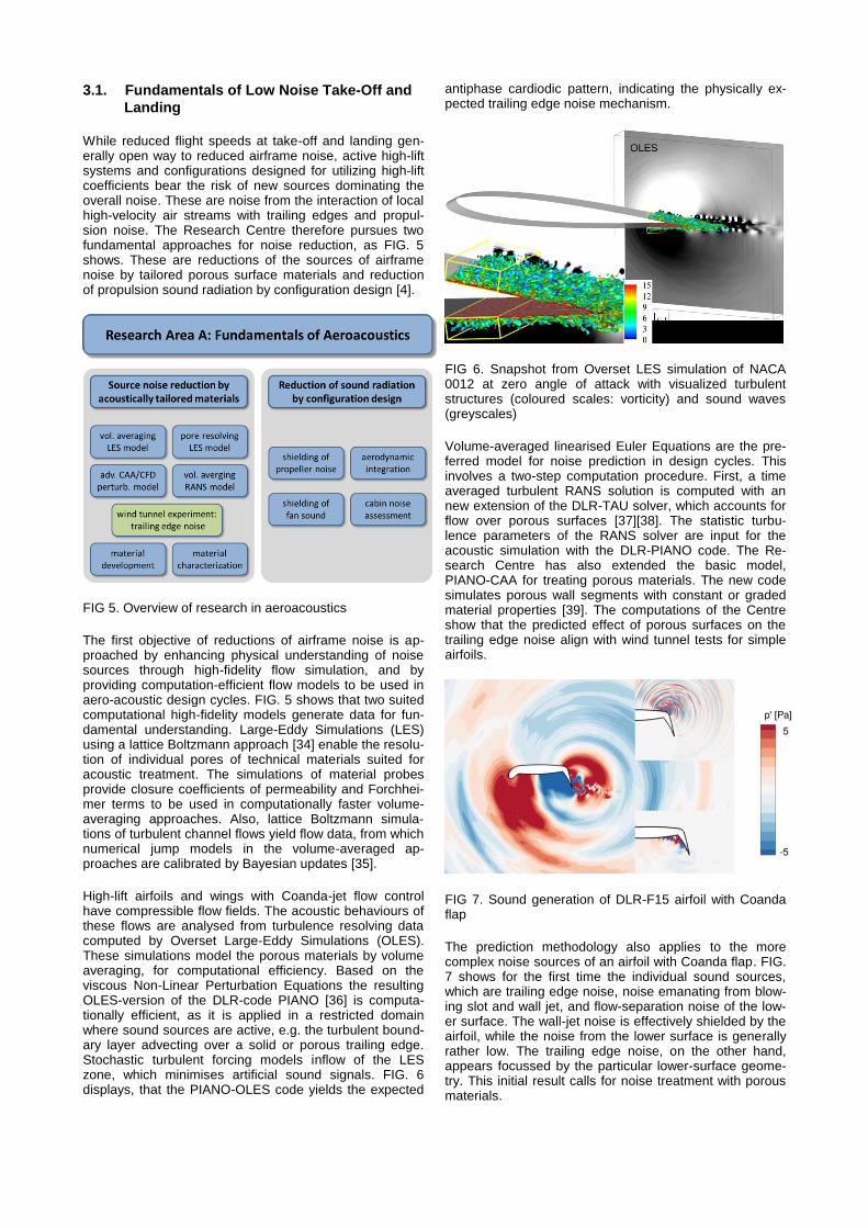
High-lift airfoils and wings with Coanda-jet flow control have compressible flow fields. The acoustic behaviours of these flows are analysed from turbulence resolving data computed by Overset Large-Eddy Simulations (OLES). These simulations model the porous materials by volume averaging, for computational efficiency. Based on the viscous Non-Linear Perturbation Equations the resulting OLES-version of the DLR-code PIANO [36] is computa-tionally efficient, as it is applied in a restricted domain where sound sources are active, e.g. the turbulent bound-ary layer advecting over a solid or porous trailing edge. Stochastic turbulent forcing models inflow of the LES zone, which minimises artificial sound signals. FIG. 6 displays, that the PIANO-OLES code yields the expected
antiphase cardiodic pattern, indicating the physically ex-pected trailing edge noise mechanism.
FIG 6. Snapshot from Overset LES simulation of NACA 0012 at zero angle of attack with visualized turbulent structures (coloured scales: vorticity) and sound waves (greyscales)
Volume-averaged linearised Euler Equations are the pre-ferred model for noise prediction in design cycles. This involves a two-step computation procedure. First, a time averaged turbulent RANS solution is computed with an new extension of the DLR-TAU solver, which accounts for flow over porous surfaces [37][38]. The statistic turbu-lence parameters of the RANS solver are input for the acoustic simulation with the DLR-PIANO code. The Re-search Centre has also extended the basic model, PIANO-CAA for treating porous materials. The new code simulates porous wall segments with constant or graded material properties [39]. The computations of the Centre show that the predicted effect of porous surfaces on the trailing edge noise align with wind tunnel tests for simple airfoils.
FIG 7. Sound generation of DLR-F15 airfoil with Coanda flap
The prediction methodology also applies to the more complex noise sources of an airfoil with Coanda flap. FIG. 7 shows for the first time the individual sound sources, which are trailing edge noise, noise emanating from blow-ing slot and wall jet, and flow-separation noise of the low-er surface. The wall-jet noise is effectively shielded by the airfoil, while the noise from the lower surface is generally rather low. The trailing edge noise, on the other hand, appears focussed by the particular lower-surface geome-try. This initial result calls for noise treatment with porous materials.

Initial experiments in the acoustic wind tunnel DLR-AWB proved significant noise reduction potentials for porous aluminium mate-rials produced using a salt infiltration technique. How-ever, full exploitation of tese potentials must avoid additional noise due to rough surface and the edges introduced by pores. Therefore, the material research of the Research Centre investigates cold rolling processes for elongating the pores in the direction of rolling. Present investigations address flow resistance and mechanical properties resulting from varied rolling processes [40]. The structural and mechanical results indicate the material to be well suited for porosity adjust-ment in a cold rolling process.
The research configuration REF3-BASIS promises fan-noise shielding and low transonic cruise drag, as outlined in Chapter 2.2. While some evidence exists for the latter claim [33], cruise drag and high-lift performance need quantification, by detailed knowledge of design sensitivi-ties. The Research Centre aims to establish such knowledge by investigating two engine integration con-cepts. These are the podded engine and full geometrical integration with the wing trailing edge. FIG 9 displays pressure contours and near-wall wing streamlines for a podded design variant at constant lift coefficient of 0.46. The engine position has obviously a strong effect on the transonic flow field of the wing. Note that unwanted flow separations can easily occur, if wing boundary layers interact with pylon and nacelle.
FIG 9. Transonic wing flow of REF3-BASIS design vari-ants: wing-body alone and podded engine [4]
While the use of UHBR engines reduces the jet noise, its effect on cabin noise for REF3 is unknown, as engine position, jet noise spectrum, and jet diameter differ largely from conventional design experience. The Research Cen-tre addresses this question by computing jet noise impact on the outer fuselage contour with the CAA solver PIANO, and by simulating transmission through the fuselage structure with the FE solver ELPASO. The structural mod-el uses PrADO aircraft design data for modelling the pri-mary structure (outer shell, frames, floor, bulk head) and secondary structure (cabin linings). ELPASO also repre-sents fuselage inside fluid regions (insulation and cabin) with strong coupling to the structure. The computation chain is now established and first results indicate physi-cally sound predictions [41].
Finally, the prediction tool PANAM assesses the relative ground noise impact of the two CRC 880 Reference Con-figurations, REF2 and REF3-BASIS. These aircraft differ by their design data according to TAB 1. The noise simu-lations employ individual approach and departure trajecto-ries, according to aircraft flight performance. FIG 10 shows trajectory details and noise data for the departure case. Noise metric for the comparison is the Effective Perceived Noise Level (EPNL). While the larger static thrust of REF2 leads to a generally steeper climb path, the ground noise levels are around 6dB larger, compared to REF3, as the configuration of REF3-BASIS effectively shields engine noise.
FIG 10. Noise prediction of REF2 and REF3-BASIS con-figurations: trajectory data (REF2 top left and REF3- BASIS top right), noise nuisance on ground for REF2 (middle) and REF3-BASIS (bottom)
FIG 8. Material reconstruc-tion from 3D X-ray scans

3.2. Efficient high lift
The Research Centre CRC 880 pursues the concept of active flow control for achieving high-lift performance beyond the capabilities of classical mechanical multi-element solutions. Employing active flow control on com-mercial transport aircraft, however bears the risk that the systems used for power supply to the active high-lift de-vices and their power consumption introduce too high costs on the overall aircraft level and render active high-lift uncompetitive. The research of the Centre therefore fo-cuses on technologies that yield compliance of active high-lift with overall design of commercial aircraft [5]. FIG 11 displays the schematic of the research efforts. Crucial is the choice of the aerodynamic approach for active flow control. The Centre employs internal blowing over careful-ly designed flap surfaces to achieve control authority for flow turning, hence making use of the Coanda effect.
FIG 11. Overview of research in efficient active high-lift
The interdisciplinary work of the CRC 880 explores four routes towards improved exploitation of the blowing pow-er:
- Reducing boundary layer losses upstream of the Coanda flap by a morphing droop nose.
- Using the benefits of boundary layer suction offered by installing distributed compressors along the wing span.
- Improving blowing efficiency by pulsed blowing. - Exploring the benefits offered by closed loop control
of wall-jet blowing.
Aerodynamic exploitation of the first two concepts as-sumed constant tangential blowing through a carefully designed blowing slot. The 2D morphing droop nose ge-ometry, as displayed in FIG 13, evolved from extensive sensitivity studies [42], while 3D flow simulations revealed its suitability for application on finite-span wings [43]. The design brought about significant gains in the ratio of max-imum lift increase over blowing momentum. The gain is expressed by the lift-gain-factor, LGF = (cLmax - cLmax,reference) / cμ, which improved by around 35% for the droop nose. Taking advantage of the combined benefits of droop nose and suction improves LGF by 55% [44]. These initial aerodynamic results, obtained at typical flight Reynolds numbers, justified in-depth research on shape-
adaptive leading edges and compact electric compres-sors, as shown below.
More recently, aerodynamic research has focused on unsteady actuation. The strategy is to gain lift by actuation of partially separated flow fields present at rather low blowing coefficients. However, reliable simulations of the flow dynamics of partially separated flows require turbu-lence resolving simulation with large computational ef-forts. On the other hand, dynamic flow actuation involves a large number of parameters of onset flow and actuation. Therefore, numerical simulation served for verifying the physical effect of dynamic actuation as displayed in FIG. 12, while experimental testing provided coverage of the parameter space.
Static blowing, cL=3.51
Dynamic 2D actuation by varying blowing slot width of +/-25%, cL=3.59, F+=0.5
FIG 12. Visualized flow structures in the wake of high-lift flap, Re = 2 · 106, α=5°, Cµ=0.02
The tests in the water tunnel employed a 2D wing section with a 25% high-lift flap, deflected by 65°, and with inter-nal blowing from a 0.07% slot [45]. Two blowing feed lines integrated custom-made electro-magnetic valves with maximum actuation frequencies of 30Hz. This allowed testing of non-dimensional actuation frequencies, F+, based on flap chord and freestream velocity, of up to 0.8. The actuation is uniform along the wingspan, providing 2D flow control. The open-loop experiments conducted so far varied Reynolds number, angle of attack, averaged mo-mentum coefficient of blowing, dynamic actuation ampli-tude, frequency, and duty cycle. The results confirmed the expectation, that dynamic actuation is effective for partial-ly separated flap flow, while no lift gains are found for mean blowing rates with fully attached flap. Fig 13 dis-plays a sample result, where dynamic blowing yields an increased Lift Gain Factor over static blowing of around 16%.

FIG 13. Effect of static and dynamic blowing on lift curves from water tunnel experiments, Re = 1.5 · 106
The results justify further experimental efforts, aiming at three-dimensional, unsteady actuation, and at closed-loop control. For this purpose, the Research Centre developed a range of sensors for flow monitoring and adaptive blow-ing slots for unsteady, segmented control of blowing mo-mentum. As useful flow information for closed-loop control include time-resolved pressure and near-wall velocity data, the objective was to develop integrated sensor sys-tems for simultaneous measurements of velocity and pressure. For pressure sensing a piezo-resistive approach is applied: a thin silicon membrane seals a pressure ref-erence chamber against the fluid. The external pressure deflects the membrane, sensed by piezo-resistive paths. The intended integration in the wet environment of water tunnel experiments and size requirements lead to rather non-conventional design solutions [46]. Eventually, the pressure sensor measures only 2.8x2.8x0.25 mm3. The hot-film sensor consists of two nickel sensing elements with sensor fabrication on a very thin spin-on polymide substrate. The thin substrate allows an upside-down ap-plication, converting the polymide foil into a protective layer [47]. Both sensors are combined with amplification electronics, forming a waterproof sensor system. After assembly, the sensor system is embedded in epoxy resin and thus waterproof shielded [48]. The sensor systems are mounted in model grooves.
The design of actuated slot-lips for controlling the blowing rates depend strongly on the model size and the intended flow environment. Water tunnel applications for small model sizes face high mechanical loads, while actuation frequencies are moderate. Screening of possible design solutions showed that trimorphic bending is a suited actu-ation principle. The advantage of this configuration is the ability to actuate in both directions. One challenging task is the sealing of piezo-ceramic and electrical connections against the ingress of moisture. Extensive screening of different materials identified a combination of an inner layer from two-component tar-epoxy resin with an outer metal foil with sputtered gold coating as suited to generate a diffusion barrier [49]. However, fatigue tests revealed that all designs have a limited lifetime, placing tight time limits on actuator operation in the water tunnel. Therefore, development and testing of lip actuators for wind tunnel models with a chord length of 600mm is currently under-way as an alternative.
The shape-adaptive droop nose provides the high-lift system with a useful angle-of-attack range before wing stall, and it eases power requirements of the blowing
system. The structural challenge lies in designing a manu-facturable structure with a suited balance between bal-ance and stiffness, withstanding stresses due to extreme deformation whilst supporting aerodynamic loads. CRC880 introduced a new skin concept featuring a cen-tral fiberglass laminate and a hybrid combination of fibre reinforced plastic stiffeners in ethylene propylene diene monomer elastomeric material [50]. The concept yields low stiffness in chord-wise direction and high stiffness along the wingspan to counter spar-bending loads [51]. Mechanical analysis addresses buckling of composite bundles [52], and more recently, crack initiation.
A practical skin faces additional challenges, which con-cern abrasion resistance, de-icing, and lightning strike protection. For lightning strike protection, an aviation-certified copper-mesh is added to the skin composite. The mesh structure allows deformation in the range nec-essary for nose drooping. Testing has shown that melting two layers of ultra-high-molecular-weight polyethylene around the copper mesh creates a hybrid material, which also suits as an outer abrasive layer. Moreover, the cen-tral part of the skin structure can be functionalised to provide skin heating, by replacing the embedded glass fibres with an electrically conductive material such as carbon fibres. Recent tests and corresponding thermal skin simulations verified the novel function-integration concept.
Determining skin ply geometries, layout of internal actua-tion mechanisms so that the leading edge precisely con-forms to cruise and high-lift target shapes is the challenge of further research. One approach considers the flexible skin supported by conventional pin-jointed linkages at predefined spanwise stations. The design process opti-mizes the skin parameters in the first design stage, fol-lowed by optimising the best location of pin joints and connections to the stringers. Input are 3D target geome-tries and loads, stacking ply sequences and material properties of the skin. Present applications address a 2.1m span droop-nose segment of the REF2 wing at mid span. FIG 14 displays strain results with maximum values in the fibreglass layers of approximately 1.5%, which result from straightening the clean wing leading edge during droop. Following manufacture and testing of a 2D function model [53], manufacture of the 3D model is now underway.
FIG 14. Results of 3D kinematics optimisation algorithm for the shape-adaptive droop nose

An alternate design approach based on Load Path Repre-sentation optimises skin and internal substructure concur-rently as opposed to sequentially. The method features a globally searching genetic algorithm for identifying the best geometry, actuation-skin load paths and thicknesses [54]. The method is still under development, as empirical input has strongly affects on the resulting designs, and the large number of design variables makes it difficult to find optimal design-space regions.
The active high-lift system requires pressurised air. An alternative to using engine bleed air is to install a number of electrically driven compressors into the wings of the aircraft. These systems consist of a transonic compressor, an electric drive and power electronics, which are inte-grated to a single unit [55]. The overall research objective is to evaluate the potentials of a joint optimisation of this unit. The design process uses aircraft wing-design data for required mass flow and pressure ratio as its input. Six compressor units are distributed within both wings, ac-cording to FIG 1. Particular challenging is the outer flap, due to space limitation of its shroud and the high pres-sure-ratio to comply with the aileron function. Hence this unit serves for integrated design studies and prototyping. An automated aero-mechanical design process was set up for the compressor, making use of multi-objective optimisation [56]. The resulting design for prototype test-ing is a mixed-flow compressor, as FIG 15 shows. This allows high pressure-ratios with a polytropic efficiency of 84.5% at its design point.
The demand for high power density lead to a permanent magnet synchronous machine for direct drive of the turbo compressor. The design methodology incorporates the interdependencies between electromagnetic design, thermal evaluation and mechanical stress analysis [58]. Thermal analysis of the final design indicates that cooling by the compressor air stream is sufficient for complying with winding isolation limits of 180°C, as the system runs only for rather short periods during take-off and landing. The loss computations predict an efficiency of 97.3% at 60,000rpm and 80kW power output.
Spatial limitations of the shroud behind the wing box also drive the design of the power electronics. The design employs unipolar silicon carbide metal oxide semiconduc-tor field-effect transistor, which feature low conduction losses. This improves inverter efficiency and reduce the necessary cooling effort. The final setup of power mod-ules is extremely compact around the compressor inlet flow with heatsink and heat exchanger. Prototype testing confirmed the thermal behaviour of the subsystem.
The Research Centre evaluated the technology impact of the shape-adaptive leading edge and of the wing shroud with distributed, compact compressors and boundary layer suction by applying overall aircraft design. This re-sulted in a comparison of the reference configurations REF2 versus the earlier design, REF0, which has no leading edge device and uses engine bleed air for blowing over the high-lift flap. Both designs accounted for one-engine-out failures. FIG 16 provides an illustration of that comparison. While the aerodynamic gains in maximum lift coefficients yield significant reductions of landing dis-tance, the use of generators and electric compressors for feeding the blown high-lift flaps result in a much smaller engine size, at only moderate weight increases of related
system mass. It is interesting that REF2 achieves the same take-off distance as REF0 (845 m BFL at sea level) with 10% less maximum thrust. This is also the conse-quence by the change to electrical power extract for the active flap system. All together reduces the relevant air-craft masses (e.g. maximum take-off mass, maximum landing mass) and, in the end, the direct operation cost, DOC.
Further research of the Research Centre addresses the compliance of engine inlets with high local angles of inci-dence at the inlet and possible non-homogeneities result-ing from large turning angles of high-lift flow. The research considers turboprop inlets of REF2 and UHBR engines of REF3. The turboprop engine features a scoop-type S-duct inlet, for which shaft penetration and wrap-around designs are scrutinised for the resulting distortions at the com-pressor location [59]. Current simulations aim at quantify-ing inlet pressure recovery and fan-plane non-homogeneities in the presence of nacelle with boundary-layer diverter and wing. First computation results indicate complex interdependencies of boundary-layer diverter and inlet shape [5].
Research on UHBR engines for wings with extremely high lift coefficients aims at identifying loss mechanisms and aerodynamic interactions of inlet and propulsor. Work began with preliminary engine design and cycle analysis. The engine design covered a number of operating points, i.e. cruise, top of climb, take-off and landing cases includ-ing power off-take for the active high-lift system and one-engine-inoperative conditions. Assuming a technology level of the year 2015 for materials and engine subcom-ponents the engine design lead to selecting a bypass ratio (BPR) of 17, which results in about 18% reduced specific fuel consumption at cruise conditions over conventional engine designs with BPR of 5 [15].
The preliminary UHBR-engine design serves as a data-base for two further lines of research. The first approach aims at knowledge of the large propulsor’s aerodynamic response to inflow non-homogeneities at high lift. The geometry of the UHBR transonic fan stage is currently determined by state-of-the-art design approaches, fol-lowed by simulations of the effect of inflow distortion oc-curring due to the over-wing mount.
The second approach models the dynamic behaviour of the rotating UHBR parts. The hybrid approach represents the flexible shafts by a finite-element formulation that allows for modal reduction. The reduced shaft models then becomes part of a multi-body representation of en-gine, pylon and wing, which allows eigenvalue analysis. The aim of this analysis is the determination whether the components have a mutual coupling, since this is a possi-ble way for energy transfer [60]. Currently, severity of coupling of UHBR-modes is analysed by unbalance exci-tation.

FIG 15. Prototype design of the electrical compressor system for mass flow rate 1.11kg/s, pressure ratio 2.33, outer diameter without flanges around 200mm [57]
FIG 16. Impact of shape-adaptive droop nose and distributed compressors on reference aircraft design
3.3. Flight dynamics
FIG 17. Schematics of research in flight dynamics
Low-speed flight of future commercial transport with short take-off and landing capabilities according to TAB 1
means flying at a much higher lift coefficient as common in present aircraft. This opens up a number of research questions in aircraft aerodynamics, aero-elasticity, and flight dynamics. FIG 17 sketches the Centre’s approach to generating new knowledge in these fields [6]. Basis for analysing flight-dynamical phenomena are the aircraft aerodynamics and structural wing design. The next step involves building of aero-elastic aircraft models and flight-mechanical models. These models serve for analysis of aero-elastic phenomena and for studies of controlling the aircraft in typical flight manoeuvres.
Reference aircraft REF2 represents the current state of technologies for efficient high-lift, as described in Chapter 3.2. While aerodynamic simulations of aircraft REF2 demonstrate an impressive gain in terms of high-lift per-formance, they also reveal severe problems of directional stability and moment balancing in failure cases. A major concern is the one engine inoperative (OEI) case. An OEI does not only generate large yawing moments, but also significant lift losses and rolling moments due to propeller-slipstream interactions with the wing. The main lift loss arises from the loss lift augmentation by the slipstream.

Furthermore, a negative engine integration effect occurs on the wing with engine off due to nacelle-induced vorti-ces, which impair the flow of high-lift flaps. FIG 18 visual-ises the adverse flow effect leading to premature wing stall. Using nacelle strakes (not shown) can reduce the strength of the nacelle vortices and delay the accompa-nied wake burst.
FIG 18. Nacelle vortex evolution at engine out for REF2 aircaft, M=0.15, α=10°
FIG 19. Slipstream-fuselage interaction for REF2 aircraft, M=0,15, α=0°, β=0°
Similarly critical is the resulting yawing moment at OEI conditions. The interaction of propeller slipstream and the high-lift wing leads to a strongly asymmetrical, aerody-namic interference of propeller wake and rear fuselage, as displayed in FIG 19. This creates significantly larger yaw-ing moments compared to the asymmetric thrust [61], [62]. The aerodynamic simulations also reveal strong couplings of thrust setting and sideslip on pitching mo-ment, leading to trim deviations.
Sizing of the wing structure based on detailed structural models generates structure data needed for analysing aero-elastic effects. The structural composite wing model represents the wing with its high-lift devices, the engine with nacelle and propeller, as well as fuel and subsys-tems, as FIG 20 shows. The model uses detailed repre-sentation of layered composite materials for shell and beam elements. Wing sizing follows a fully stressed ap-proach covering 12 load cases from relevant ground and
flight cases. Shell and beam dimensions derive from structural failing indices, which respect the relevant com-posite failure cases. It turns out that the detailed structure sizing leads to comparable mass to the PrADO design module for preliminary aircraft design.
FIG 20. FEM wing model of REF2 in landing configuration
The detailed wing structure forms the basis for the re-search on aero-elastic wing behaviours. Firstly, it serves for studying compliance of the elastic structure under aerodynamic loads with geometry requirements on blow-ing slots etc. The detailed mass distribution of the wing is further the input for modal reduction needed for flutter analysis.
The flutter behaviour of wings with active circulation con-trol can deviate significantly from the behaviour of conven-tional wings [64], due the nonlinear response of forces and moments to onset flow parameters. Since parameter studies with three-dimensional aerodynamic models and active high-lift flaps are very expensive, the Research Centre developed a reduced-order model for representing the aero-elastic stability over the whole range of flight. The reduced model represents the dynamic structure by modal reduction of the detailed FEM wing model as de-scribed above. The aerodynamic forces and moments due to local plunging and rotation are determined by the re-sults of RANS-solutions for 2D wing sections, yielding the aerodynamic load vector. This model identifies circulation control flutter as the result of wing bending modes and nonlinear aerodynamic response [65]. Further develop-ment of the reduced aerodynamic model considers 3D corrections for induced downwash based on lifting-line theory [66]. Therefore, the extended model represents the evolution of nonlinear aerodynamics over the wingspan better.
The history of STOL aircraft research shows that flying with active high-lift systems can lead to unfavourable handling qualities and even unstable states with particular problems occurring in lateral aircraft motion. Flight me-chanical simulations serve for understanding the dynam-ical behaviour of the Centre’s reference aircraft. These simulations require the transfer of high-fidelity CFD data into a capable flight mechanics model, which represents the rather nonlinear effects of engine and control surfac-es, along with the sensitivities to the aircraft flight-state vector [67]. In addition, the flight mechanics model was

extended to represent the aero-elastic degrees of freedom by integrating the reduced order model described above.
The flight dynamical database allowed a range of in-depth analyses. In aircraft performance, steep climb and land-ing trajectories and low approach speeds are possible, but climb rates with OEI are critical, due to the large induced drag [6]. Furthermore, the circulation control system pro-vides the exceptional possibility to uncouple pitch ampli-tude, angle of attack and lift, opening the opportunity to integrate an advanced flight-path control system. Coupling of the flight mechanical modes and aero-elastic modes is generally weak, even though rapid control input can excite structural modes [6]. A major focus of current research are flight-mechanical consequences of the nonlinear in-teraction of propeller slipstream with the aft fuselage, which become an important factor of directional stability. The database reveals a strong dependence of the lateral motion on angle of attack and thrust setting, with varying instability intervals for small yawing angles [68]. There exist flow conditions where the vertical tail even loses its stabilising effect [62]. The interaction of slipstream and fuselage has a strong impact on pitching moment, thereby coupling lateral and longitudinal motions. Further anal-yses screens aircraft eigenmodes with frequency and damping used as criteria for handling quality over air-speed and yaw angle [68]. Six-degrees-of-freedom simu-lations quantify aircraft response to sudden crosswind. Further simulations went into crosswind landings and investigated the use of differential blowing along the span. In conclusion, the aircraft shows an eccentric directional stability, with its equilibrium at sideslip angles of β±10° [68]. It is believed that such aircraft can be stabilized by an adequate control system.
The flight-dynamics input data and flight-mechanical models are not precisely known. Instead, they involve engineering estimates for replacing lack of knowledge and uncertainty due to inherent model errors. The simplest way to quantify uncertainties is the Monte Carlo method; however, this is computationally inefficient. The Centre has access to a number of more efficient numerical meth-ods that range from stochastic collocation, which do not need changes to the physical computation model, up to Stochastic Galerkin formulations, which incorporate the stochastic degrees of freedom into the solver of the physi-cal model [69]. For solving the uncertain flight dynamics equations a number of parameters receive uncertainty intervals, according to expert’s input. FIG 21 presents a sample result of uncertainty transmission through the flight-mechanical simulation. Current work in uncertainties deals with uncertainty quantification of lateral motion and robust controller design.
FIG 21. Sensitivity of phugoid response to uncertainty of aerodynamic parameters for REF0 reference aircraft in landing configuration: mean value and 3σ region [70]
4. CONCLUSIONS
The Collaborative Research Centre CRC 880 combines the competencies of Technische Universität Braun-schweig, Universität Hannover and the German Aero-space Center, DLR, for fundamental and applied research in high lift of future commercial aircraft. The research activities combine the disciplines of aerodynamics, aeroa-coustics, materials, structures, adaptronics, turbomachin-ery, flight mechanics and scientific computing. The Centre has made good progress in methods for aero-acoustic design, in understanding noise sources, in exploring flexi-ble and efficient high-lift systems using active blowing, and in analysing critical dynamic behaviours of future commercial aircraft with STOL capabilities. Future work will validate the new concepts with carefully designed experiments and further investigate multidisciplinary as-pects of design approaches. The Centre welcomes oppor-tunities for new co-operations with other researchers in the field.
Acknowledgement The funding of the Collaborative Research Centre CRC 880 by the German Research Foundation, DFG, is thankfully acknowledged.
References
[1] Flightpath2050 – Europe’s Vision for Aviation, Report on the High Level Group on Aviation Research, ISBN 978-92-79-19724-6, 2011, www.acare4europe.org.
[2] Henke, R., Lammering, T., Anton, E.: Impact of an Innovative Quiet Regional Aircraft on the Air Trans-portation System. Journal of Aircraft, Vol. 47, No. 3, 2010.
[3] Radespiel, R., Heinze, W.: SFB 880 – fundamentals of high-Lift for future commercial aircraft. CEAS Aer-onautical Journal, Vol. 5, No. 3, 2014.
[4] Delfs, J.W., et al: Aircraft and Technology for Low Noise Short Takeoff and Landing, AIAA Applied Aer-odynamics Conference, 5-8 June 2017, AIAA-2017-3558, 2017.
[5] Kauth, F. et al: Progress in Efficient Active High-Lift, AIAA Applied Aerodynamics Conference, 5-8 June 2017, AIAA-2017-3559, 2017.
[6] Horst, P. et al: Flight Dynamics of Transport Aircraft with Active High-Lift, AIAA Applied Aerodynamics Conference, 5-8 June 2017, AIAA-2017-3560, 2017.
[7] Werner-Westphal, C., Heinze, W., and Horst, P.: Multidisciplinary Integrated Preliminary Design Ap-plied to Unconventional Aircraft Configurations. Jour-nal of Aircraft, Vol. 45, No. 2, 2008.
[8] Werner-Spatz, C., Heinze, W., Horst, P., Radespiel, R.: Multidisciplinary Conceptual Design for Aircraft with Circulation Control High-Lift Systems. CEAS Aeronautical Journal, Vol. 3, pp. 145-164, 2012.
[9] Weiss, T.W.: Automated Aerodynamic Model Gener-ation in Preliminary Aircraft Design. Deutscher Luft- und Raumfahrtkongress, 2016.
[10] Koeppen, C.: Method for Model-Based Estimations of System Mass in Aircraft Pre-Design. Proceedings of the 66th Annual Conference of the Society of Al-lied Weight Engineers, SAWE Paper No. 3428, Los An-geles, CA, 2007.
[11] Teichel, S. H., Dörbaum, M., Misir, O., Merkert, A., Mertens, A., Seume, J. R., and Ponick, B., Design considerations for the components of electrically powered active high-lift systems in civil aircraft,"

CEAS Aeronautical Journal, Vol. 6, No. 1, 2015, pp. 49-67.
[12] Mattingly, J. D., Heiser, W. H., and Daley, D.H., Air-craft Engine Design. Appendix H Turboprop Engine, AIAA, New York, 1987, pp. 507-531.
[13] Baum, J. A., Dumais, P. J., Mayo, M. G., Metzger, F. B.,Shenkman, A. M., and Walker, G. G.: Prop-Fan Data Support Study, Technical Report. NASA CR-152141, Moffett Field, CA, Feb. 1978.
[14] Kurzke, J., GasTurb 12 - Design and Off-Design Performance of Gas Turbines, GasTurb GmbH, start-er guide for users, Aachen, Germany, 2015.
[15] Giesecke, D., Lehmler, M., Friedrichs, J., Blinstrub, J., Bertsch, L., Heinze, W.: Evaluation of Ultra-High Bypass Ratio Engines for an Over-Wing Aircraft Con-figuration Design studies, submitted to Journal of the Global Power and Propulsion Society, 2017.
[16] Krosche, M., Heinze, W., Robustness Analysis of an Aircraft Design for Short Takeoff and Landing, Jour-nal of Aircraft, Volume 52, Number 4, 2015, pp 1235-1246.
[17] Rang, J., Heinze, W., Friedmann, N., Optimisation of a CESTOL configuration under consideration of un-certainties. In: Radespiel, R., Semaan, R. (Eds.): SFB 880 – Fundamentals of high-lift for future commercial aircraft. ISBN 978-3-928628-90-7, 2017.
[18] Rang, J., Heinze, W.,An optimal configuration of an aircraft with high lift configuration using surrogate models and optimisation under uncertainties, 12th World Congress on Structural and Multidisciplinary Optimization, Braunschweig, Germany, June 5-9, 2017.
[19] Bertsch, L., Noise Prediction within Conceptual Air-craft Design, DLR Forschungsbericht, ISRN DLR-FB-2013-20, 2013.
[20] Bertsch, L., Heinze, W., Lummer, M.: Application of an Aircraft Design-To-Noise Simulation Process, AIAA-2014-2169, 2014.
[21] Pott-Pollenske, M., Dobrzynski, W., Buchholz, Guérin, H.S., Saueressig, G., and Finke, U., Airframe Noise Characteristics from Flyover Measurements and Predictions, AIAA-2006-2567, 2006.
[22] Dobrzynski, W., Chow, L., Guion, P., Shiells, D., A European Study on Landing Gear Airframe Noise Sources, 6th AIAA/CEAS Aeroacoustics Conference, 12-14 June 2000, La-haina Hawaii/USA.
[23] Stone, J.R., Groesbeck, D.E., Zola, Z.L., Convention-al profile coaxial jet noise prediction", AIAA Journal, vol. 21, No. 3.
[24] Heidmann, M. F.: Interim Prediction Method for Fan and Compressor Source Noise,Technical Memoran-dum X-71763, NASA, 1979.
[25] Lummer, M., Maggi-Rubinowicz Diffraction Correction for Ray-Tracing Calculations of Engine Noise Shield-ing, AIAA-2008-3050, 2008.
[26] Rossignol, K.-S., Pott-Pollenske, M., Delfs, J., Sil-bermann, J., and Pereira Gomes, J., Investigating Noise Shielding by Unconventional Aircraft Configura-tions, AIAA 2017-3195, 2017.
[27] Magliozzi, B., Hanson, D.B., Amiet, R.K., Propeller and Propfan Noise. In: Aeroacoustics of Flight Vehi-cles: Theory and Practice ed. H.H. Hubbard, Chapter 1, NASA, 1991.
[28] Dierke, J. et al.: „Installation Effects of a Propeller Mounted on a High-Lift Wing with a Coanda Flap. Part II: Numerical Investigation and Experimental Val-idation. In: 20th AIAA/CEAS Aeroacoustics Confer-ence. AIAA-2014-3189, 2014.
[29] Blinstrub, J., Heinze, W., Bertsch, L., Simons, D.G., Snellen, M., System noise assessment of an aircraft with Coanda flaps, READ Conference 2016.
[30] Bertsch, L., Schäffer, B., Guerin, S., Herr, M., To-wards an uncertainty analysis for parametric aircraft system noise prediction, 12th ICBEN Congress on Noise as a Public Health Problem, Zürich, 18-22 June, 2017.
[31] Müller, L.; Heinze, W.; Kozulovic, D.; Hepperle, M. Radespiel, R. : Aerodynamic Installation Effects of an Over-the-Wing Propeller Installation Effects on a High-Lift Configuration, AIAA Journal of Aircraft, Vol. 51, No. 1, 2014.
[32] Müller, L., Kozulovic, D., Radespiel, R.: Aerodynamic performance of an over-the-wing propeller configura-tion at increasing Mach number. CEAS Aeronautical Journal, Vol. 5, No. 3, 2014.
[33] Hooker,J.R., Zeune,C. and Agelastos,A., Over Wing Nacelle Installations for Improved Energy Efficiency, 31st AIAA Applied Aerodynamics Conference, San Diego, CA, USA, June 24-27, 2013.
[34] Geier, M. , Schönherr, M., Pasquali, A., Krafczyk, M., The cumulant lattice Boltzmann equation in three di-mensions: Theory and validation, Computers & Math-ematics with Applications, vol. 70, No. 4, 2015.
[35] Kumar P., Friedman, N., Zander, E., Radespiel, R., Bayesian calibration of VRANS model parameters for turbulent flow simulations over porous materials. New Results in Numerical and Experimental Fluid Mechan-ics XI, Springer, 2017.
[36] Bernicke, P., Akkermans, R.A.D., Ewert, R., Dierke, J., Overset LES for Trailing-Edge Noise Computa-tions, AIAA-2017-3170, 2017.
[37] Mößner, M., Radespiel, R., Modelling of turbulent flow over porous media using a volume averaging ap-proach and a Reynolds stress model. Computers & Fluids, Vol. 108, 2015.
[38] Mößner, M., Radespiel, R., Flow Simulations over Porous Media – Comparisons with Experiments, Computers & Fluids, 2017, http://dx.doi.org/10.1016/j.compfluid.2017.03.002.
[39] Rossian, L., Ewert, R., Delfs, J.W., Evaluation of Acoustic Jump Conditions at Discontinuous Porous Interfaces, AIAA-2017-3505, 2017.
[40] Lippitz, N., Maudarbocus, S., and Rösler, J., The influence of cold rolling on the pore morphology and flow resistivity of porous aluminum", Sixth Interna-tional Conference on Porous Media and Its Applica-tions in Science, Engineering and Industry, 2016.
[41] Blech, C., Appel, C. K., Langer, S.C., Delfs, J. W., Numerical prediction of cabin noise due to jet noise excitation of two different engine configurations, Pro-ceedings of ICSV, London, 2017.
[42] Burnazzi, M., Radespiel, R.: Assessment of leading-edge devices for stall delay on an airfoil with active circulation control, CEAS Aeronautical Journal, Vol. 5, No. 4, 2014.
[43] Burnazzi, M., Thiemeier, J., Radespiel, R.: Numerical Stall Behavior Investigation of an Aircraft equipped with Coanda Flap and Droop Nose, Notes on Numer-ical Fluid Mechanics and Multidisciplinary Design, Vol. 133, Springer-Verlag, 2016.
[44] Burnazzi, M., Radespiel, R.: Synergies between suc-tion and blowing for active high-lift flaps, CEAS Aero-nautical Journal, Vol.6, No. 2, 2015.
[45] El Sayed, Y., Semaan, R., Radespiel, R.: Open Loop Control on a Coanda Flap Water Tunnel Model. AIAA-2017-3247, 2017.

[46] Schwerter, M., Gräbner, D., Hecht, L., Vierheller, A., Leester-Schädel, M., and Dietzel, A., Surface-Passive Pressure Sensor by Femtosecond Laser Glass Struc-turing for Flip-Chip-in-Foil Integration," Journal of Mi-croelectromechanical Systems, Vol. 25, No. 3, 2016, pp. 517-523.
[47] Schwerter, M., Hecht, L., Koch, E., Leester-Schädel, M., and Dietzel, A., Liquid polyimide as a substrate for aeronautical sensor systems," Proc. SPIE 9435 Sensors and Smart Structures for Civil, Mechanical, and Aerospace Systems, 2015.
[48] Schwerter, M., Leester-Schädel, M., and Dietzel, A., \Waterproof sensor system for simultaneous pressure and hot-film flow measurements," Sensors and Ac-tuators A: Physical, 2017.
[49] Behr, C., Schwerter, M., Wierach, P., Leester-Schädel, M., Dietzel, A., Büttgenbach, S., and Sinapius, M., Sensor and Actuator Systems for Active Flow Control, NFL-Forschungsbericht 2015-04, ISBN 978-3-928628-67-9, 2015.
[50] Schmitz, A. and Horst, P., A New Curvature Morphing Skin: Manufacturing, Experimental and Numerical In-vestigations, European Conference on Composite Materials, 22-26 June 2014, Seville, Spain, 2014.
[51] Schmitz, A., Horst, P., Numerical modelling of the change in stiffness properties of cross-ply laminates subjected to large bending curvatures. Key Engineer-ing Materials. Vol. 577. Trans Tech Publications, 2014.
[52] Schmitz, A., Horst, P., Buckling of multiple discrete composite bundles in the elastomeric foundation of a curvature-morphing skin, Composite Structures, Vol-ume 134, pp 1014-1023, 2015.
[53] Rudenko, A., Hannig, A., Monner, H. P., Horst, P., Extremely Deformable Morphing Leading Edge: Op-timization, Design and Structural Testing. Journal of Intelligent Material Systems and Structures (accept-ed), 2017.
[54] Vasista, S., Rose, M., and Monner, H. P., Optimiza-tion Tool Assessment for a Large-displacement Compliant Morphing Wing Leading Edge, 27th Inter-national Conference on Adaptive Structures and Technologies ICAST2016, Lake George, NY, 2016.
[55] Teichel, S. H., Dörbaum, M., Misir, O., Merkert, A., Mertens, A., Seume, J. R., and Ponick, B., Design considerations for the components of electrically powered active high-lift systems in civil aircraft, CEAS Aeronautical Journal, Vol. 6, No. 1, 2015.
[56] Teichel, S. H., Verstraete, T., and Seume, J. R., Op-timized Multidisciplinary Design of a Small Transonic Compressor for Active High-Lift Systems, Proceed-ings of International Gas Turbine Congress 2015 To-kyo.
[57] Kauth, F., Narjes, G., Müller, J., Mertens, A., Ponick, B., and Seume, J. R., Highly Integrated Electrically Driven Active High-Lift Compressor Systems for Fu-ture Civil Aircraft, Proceedings of Greener Aviation Conference 2016, 2016.
[58] Narjes, G., Müller, J., Mertens, A., Ponick, B., Kauth, F., and Seume, J. R., Design Considerations for an Electrical Machine Propelling a Direct Driven Turbo Compressor for Use in Active High-Lift Systems, Pro-ceedings of International Conference on Electrical Systems for Aircraft, Railway, Ship Propulsion and Road Vehicles, 2016.
[59] Atalayer, C., Friedrichs, J., and Wulf, D., S-Duct In-take Conguration Sensitivity of a Highly Loaded Tur-
boprop by CFD Methods, ASME Turbo Expo 2015, GT2015-42932, 2015.
[60] Müller. T. S. and Hennings, H., Rotordynamic Valida-tion of a Twin Rotor-bearing System Considering Gy-roscopic Forces and Bearing Dynamics with a Multi-body Formulation: Application to a Geared UHBR Gas Turbine, 65. Deutscher Luft- und Raumfahrtkon-gress, 2016.
[61] Keller, D. and Rudnik, R., Numerical Investigation of Engine Effects on a Transport Aircraft with Circulation Control, Journal of Aircraft, Vol. Vol. 52, No. No. 2, 2015.
[62] Keller, D. and Rudnik, R., Numerical Investigations of Aerodynamic Properties of a Propeller Blown Circula-tion Control System on a High Wing Aircraft, CEAS Aeronautical Journal, Vol. 7, No. 3, 2016.
[63] Sommerwerk, K. and Haupt, M., Design analysis and sizing of a circulation controlled CFRP wing with Coanda flaps via CFD-CSM coupling, CEAS Aero-nautical Journal, Vol. Vol. 5, No. 1, 2014.
[64] Haas, D. J. and Chopra, I., Flutter of circulation con-trol wings, Journal of Aircraft, Vol. 26, No. 4, 1989.
[65] Dinkler, D. and Krukow, I., Flutter of Circulation-Controlled Wings, CEAS Aeronautical Journal, Vol. 6, No. 4, 2015.
[66] Sommerwerk, K., Krukow, I., Haupt, M. C., and Din-kler, D., Investigation of Aeroelastic Effects of a Cir-culation Controlled Wing, Journal of Aircraft, Vol. 53, No. 6, 2016.
[67] Diekmann, J. H. and Hahn, K.-U., Effect of an active high-lift system failure during landing approaches, CEAS Aeronautical Journal, Vol. 6, No. 2, 2015.
[68] Diekmann, J.H., Flight Mechanical Challenges of STOL Aircraft Using Active High-Lift, AIAA-2017-3561, 2017.
[69] Rosic, B. V. and Diekmann, J. H., Methods for the Uncertainty Quantification of Aircraft Simulation Mod-els," Journal of Aircraft, Vol. 52, No. No. 4, 2014.
[70] Friedmann, N., Krosche, M., Rosic, B., Rang, J., Matthies, H.G., Uncertainty Quantification for a High Lift Aircraft Design and its Dynamic Simulation Model. NFL-Forschungsbericht 2015-04, ISBN 978-3-928628-67-9, 2015.