hf communication equipment i9m-65
TRANSCRIPT

tqcq j. tzJeteitt,
HF COMMUNICATION EQUIPMENT I9M-65
ti!!!lioul Inn Hu
W&11, iittIIl4?III! !ti#
lippii1:111111111iiiii1111111111111 twill ii:11111111itti
1H1 IIHIIiII 1.1.„,„ fifiinittiiiiiinitt!prillip Itt!!!!!!!!!"ffile"
iltwil!!: .

%
-
CONTENTS
Typical Systems page 2
HF COMMUNICATION EQUIPMENT CATALOG
1964-1965
Collins Radio Company, with more than 30 years
of experience in research, development and man-
ufacture of equipment and systems for use in the
HF spectrum, has contributed many distinctive
improvements in HF communication equipment
design. These include automatic tuning systems,
stable frequency sources, Mechanical Filters, lin-
ear power amplifiers, antenna coupling methods,
highly efficient broadband antennas and single
sideband systems for a wide range of applications.
The use of rigid, uncompromising standards of ex-
cellence, beginning in the laboratory and continu-
ing through every production step, assures the cus-
tomer of dependable, high performance equip-
ment of proven quality.
As a result of a continuing development program,
Collins offers a complete line of single sideband
equipment to meet virtually all HF communica-
tion requirements. The equipment and systems are
equally applicable to surface, transportable, air-
borne or marine communication for both civilian
and government needs. Collins' single sideband
systems aid in spectrum conservation and greatly
improve the quality and flexibility of high fre-
quency communication.
Currently in use throughout the world, in such ap-
plications as Strategic Air Command networks,
Naval Tactical Data System, NATO's defense line
in the North Atlantic and Arctic regions, satellite
tracking systems and commercial airlines, Collins
HF systems are providing consistently high per-
formance and outstanding reliability.
e iA mee>1111 CO 1,11 NS
Receivers page 17
Transmitting Equipment page 24
Transceivers page 38
Communication Systems page 59
Universal Radio Group Equipment page 81
Antennas page 92
Antenna Couplers and Accessories page 100
Data and Teletypewriter Equipment page 116
Test Equipment page 129
Amateur Radio Equipment page 133
Tables, Charts and Graphs page 142
Cross Reference of Military Nomenclatures page 153
Index by Type Number page 156
Index by Function page 158
Glossary page 160
O Collins Radio Company 1944
For fast location of equipment, flip the pages until you reach the section where the black marker in the right margin is opposite the appropriate diamond above.

T> ideal 11E Com m n kin t S> stems
EXCITER
TERMINATION EQUIPMENT
Collins Radio Company, a pioneer in high frequency single sideband equip-ment development, offers a wide selec-tion of integrated systems, as well as in-dividual receivers, transmitters and transceivers to greatly improve the qual-ity and flexibility of communication. Outlined in this section are typical sys-tems, together with salient features and characteristics, for airborne, fixed point-to-point, shipboard, mobile, transport-able and tactical military communica-tion applications. Information regard-ing specific units and options are de-tailed on the referenced pages.
POWER AMPLIFIER
RECEIVER
ANTENNA I COUPLER
2
Mobile HF Communication ,Sstems
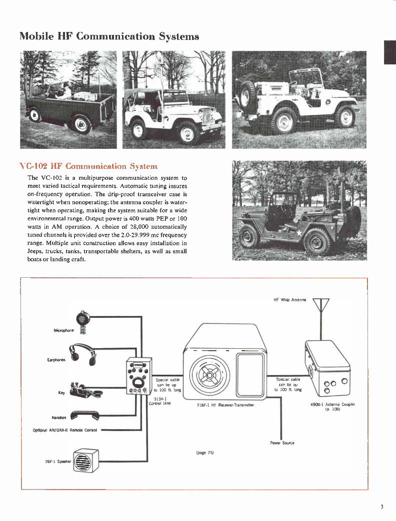
VC-102 11F Communication System
The VC-102 is a multipurpose communication system to
meet varied tactical requirements. Automatic tuning insures
on-frequency operation. The drip-proof transceiver case is
watertight when nonoperating; the antenna coupler is water-
tight when operating, making the system suitable for a wide
environmental range. Output power is 400 watts PEP or 100
watts in AM operation. A choice of 28,000 automatically
tuned channels is provided over the 2.0-29.999 mc frequency
range. Multiple unit construction allows easy installation in
Jeeps, trucks, tanks, transportable shelters, as well as small
boats or landing craft.
Microphone
Earphones
Key
Handset
o.o.o
Optional AN/GRA-6 Remote Control
76F-1 Speaker
Special cable can be up
to 100 ft. long
313V-1 Control Unit 718F-1 HF Receiver-Transmitter
(Page 75)
VHF Whip Antenna
Special cable can be up
to 100 ft. long
Power Source
49013-1 Antenna Coupler (p. 108)
3

Mobile HF Communication Systems
3\1S-1 B 100 VS all Mobile Transeeker
The 32MS- I B is a compact 100 watt PEP SSB transceiver
with a choice of single sideband or compatible AM on any of
four preset frequencies in the 1.6-15.0 mc range. Plug-in
power supplies permit operation from either 12 I/ dc, 28 y dc
or 115 y or 230 v, 50-400 cps sources. Three optional control
unit styles will meet most installation requirements.
32MS-18 100 Watt Mobile Transceiver
(p 39)
Optional Remote Control Power Source
180V-2 Antenna Coupler
(p. 43)
tniNersal Radio Group
The Collins Universal Radio Group equipment provides a
mobile HF system of extreme installation flexibility. Specific
system components can he selected to meet individual needs.
Equipment can he chosen for a receiver, transmitter or trans-
Optional 70013-2 Teletypewriter Converter
(p. 122)
RTTY
Earphones
Microphone
Handset
ceiver to operate on either 28,000 or 280,000 automatically
tuned channels in the 2.0-29.9999 mc frequency range. Mode
choice includes USB, LSB, ISB, AM, optional FSK. Primary
power can be 27.5 y dc or 120 y or 208 v, 400 cps, 3 phase.
6718-1 Receiver-Exciter
(p. 46)
714Y-1, -2 Control Unit (p. 90)
Power Source
4901 1 Antenna Coupler
(p. 109)
4

Mobile HF Communication Systems
YC-104 Vehicular IIF-UHF Communication System
The VC-I04 HF-UHF System is normally installed in a
standard M38A 4 x 4 Vs -ton military vehicle. It provides 400
watts PEP or 100 watts in AM, CW and FSK on 28,000 au-
tomatically tuned channels in the 2.0-29.999 mc range. In
UHF, output power is 20 watts in AM on any of 1750 100
kc increments in the 225.0-399.9 mc frequency range.
VC-106 Vehicular 11F-L IIF Communication System
The VC-106 HF-UHF System is designed for installation in
a 4 x 4 Vs -ton M151 military vehicle. It provides 400 watts
PEP or 100 watts in AM, CW or FSK on 28,000 automati-
Microphone
Earphones
Key
Handset
OPtional AN/GRA-6 Remote Control
76F-1 Speaker
Microphone
Earphones
Optional AN/GRA-6 Remote Control
HF Whip Antenna
Special cable can be up
to 100 ft. long
Power Source
cally tuned channels in the 2.0-29.999 mc range. In UHF
operation, it has 20 watts AM power output on any of 1750
100 kc channel increments in the 225.0-399.9 mc range.
Special cable can be up
to 100 ft. long
313V-1 Control Unit
Power Source
111
718F-1 HF Receiver-Transmitter
(VC-104 p. 77)
(VC-106 p 79)
718M-1 UHF Receiver-Transmitter
VC-104 or VC-106 Vehicular HF-UHF Communication System
4908-1 Antenna Coupler (p. 108)
AS-390
UHF Discone
Antenna
5

Airborne Systems
AJN/A RC-80 ‘irix)rne I 1 F Communication S" stein
The AN/ARC-80 is an airborne single sideband system espe-
cially suited for data handling, as well as voice or CW com-
munication. It offers a choice of LSB. USB or ISB modes on
channels spaced I kc throughout the 2.0-29.999 mc range.
\L I Transmitter
Microphone
Speaker
Earphones
Data
\
RF Amplifier
Amplifier-Control
Antenna Coupler
Transmit power is 900 watts PEP. An efficient trailing wire
antenna for speeds up to 300 knots is adjusted automatically
to the correct frequency. Frequency variation can be man-
ually adjusted to zero with a received standard signal.
Low Pass Filter
Radio Set Control
(page 49)
Receiver
6

Airborne Systems
Universal Radio Group
The Collins Universal Radio Group offers a choice of oper-
ating modes and installation flexibility for airborne applica-
tions in the 2.0-29.9999 mc frequency range. A choice of
either 1.0 kc or 0.1 kc channel increments is available. Modes
of operation, implemented by plug-in circuit cards, include
USB, LSB with 3 kc or 6 kc bandwidths, or AM. Power out-
Earphone
Speaker
Microphone
Power Source
6718-1 Receiver-Exciter (p. 46)
RTTY
Control Unit
618T Transceiver
The versatile 618T provides 1 kc channel increments
throughout the 2.0-29.999 mc range with 400 watts PEP out-
put is 1 kw PEP. Individual units are housed in ATR,
ARINC Specification 404 cases. System control mounts in
standard aircraft console. Primary power source can be
27.5 y dc; or 120 y or 208 v, 400 cps, 3 phase. Receive-only
or transmit-only systems can be selected, as well as the trans-
ceiver shown below.
548L-4 1 KW Power Amplifier Antenna
(p. 37) 180R-6
Antenna Coupler (p. 102)
309A-213 Coupler Control (p. 102)
put on single sideband or 100 watts on AM, CW or FSK. A
teletypewriter can be used with an optional converter.
7
Fixed Station HF Communication Systems
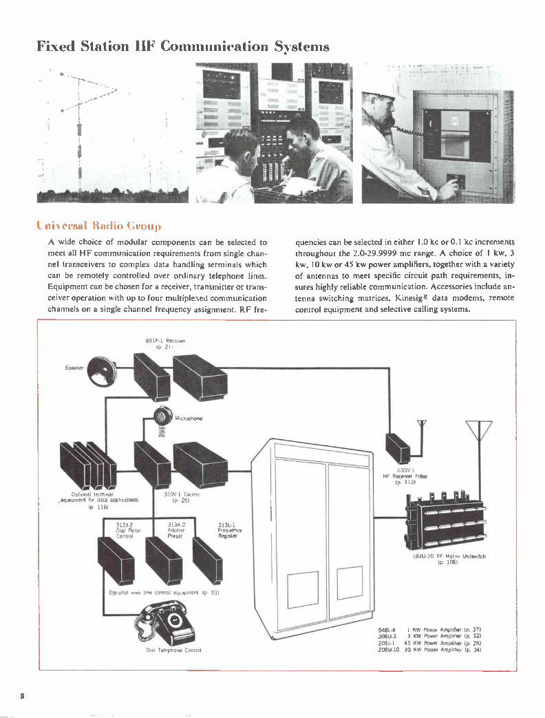
ni N ersal Radio Croup
A wide choice of modular components can be selected to
meet all HF communication requirements from single chan-
nel transceivers to complex data handling terminais which
can be remotely controlled over ordinary telephone lines.
Equipment can be chosen for a receiver, transmitter or trans-
ceiver operation with up to four multiplexed communication
channels on a single channel frequency assignment. RF fre-
quencies can be selected in either 1.0 kc or 0.1 kc increments
throughout the 2.0-29.9999 mc range. A choice of 1 kw, 3
kw, I 0 kw or 45 kw power amplifiers, together with a variety
of antennas to meet specific circuit path requirements, in-
sures highly reliable communication. Accessories include an-
tenna switching matrices, Kinese data modems, remote
control equipment and selective calling systems.
Speaker
Optional terminal ,equipment for data applications
116)
651F-I Receive, 1P 21)
Microphone
310V•1 Exciter (P. 251
313L-1 Frequency Register
Optional wire line ..inent 1p 83)
Dial Telephone Lontrol
635V-1 HF Receiver Filter
(p. 113)
184U 10 RF Matrix Uniswitch (p. 106)
548L-4 I KW Power Amplifier (p. 37) 208(3-3 3 KW Power Amplifier (p. 32) 205J-1 45 KW Power Amplifier (p. 28) 208U-10 10 KW Power Amplifier (P. 34)
8
Fixed Station HF Communication Systems
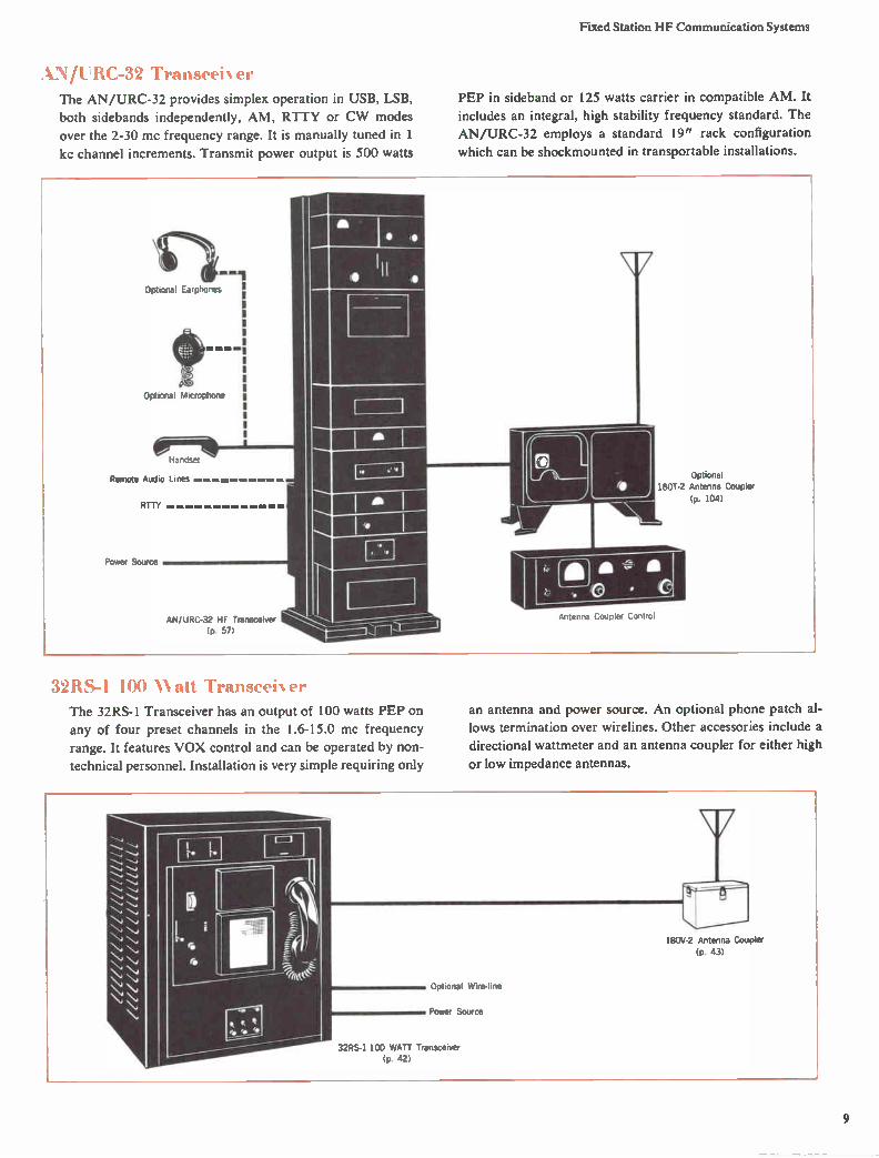
‘N/UTRC-32 Transeeher
The AN/URC-32 provides simplex operation in USB, LSB,
both sidebands independently, AM, RTTY or CW modes
over the 2-30 mc frequency range. It is manually tuned in 1
kc channel increments. Transmit power output is 500 watts
PEP in sideband or 125 watts carrier in compatible AM. It
includes an integral, high stability frequency standard. The
AN/URC-32 employs a standard 19" rack configuration
which can be shockmounted in transportable installations.
Optional Earphones
N :•••: • .1.•11.111M
Optional Microphone
Handset
Remote Audio Lines
RTTY
Power Source
AN/URC-32 HF Transceiver (p 57)
32RS-1 100 Watt Transceher The 32RS-1 Transceiver has an output of 100 watts PEP on
any of four preset channels in the 1.6-15.0 mc frequency
range. It features VOX control and can be operated by non-
technical personnel. Installation is very simple requiring only
Optional 180T-2 Antenna Coupler
(p. 104)
Antenna Coupler Control
an antenna and power source. An optional phone patch al-
lows termination over wirelines. Other accessories include a
directional wattmeter and an antenna coupler for either high
or low impedance antennas.
180V-2 Antenna Coupler
(p. 43)
Optional Wire-line
Power Source
32RS-1 100 WATT Transceiver (p. 42)
9

Transportable HF Communication Systems ‘YN. :..-I .1ir 'Transportable IIF Communication Sstem The ANNA-I is a complete air transportable HF communi-
cation terminal, including a maintenance facility, housed in
two S-141 A/G style shelters. It provides either simplex or
full duplex operation on two independent radio circuits,
which are automatically tuned in 0.1 kc channel increments
throughout the 2.0-29.9999 mc frequency range. Choice of
modes includes USB, L.SB. ISB or AM. Voice frequency tele-
graph facilities may be employed. Basic system units are of
the highly reliable Universal Radio Group type. Power is
supplied by a 30 kw diesel generator.
789R-1
IF Translator
(p 88)
Aucho RTTY Inputs
6182-4
RF Translator
(p 87)
635V-1
HF Recelver F,Iter
(p. 112)
789R-1 IF Translator 618Z-4 RF Translator 635V-1 I-IF Recenrer Filter
(p 88) (p. 87) (p. 112)
789T-1
IF Translator
(p. 89)
789T-1
IF Translator
(p. 89)
Operator Console
618Z-4
RF Translator
(p 87)
6I8Z-4
RF Translator
(p. 871
548L-4
1 KW Power AmpIdler
(p 371
548L-4
1 KW Power AmpIdler
(p. 37)
Page 6,;)
Patch Pane,
309A-2D
Coupler Control
(p. 102)
180R-6 Antenna Coupler
(p. 102)
309A-2D
Coupler Control
(p. 102)
-s1N/TSC-38 Transportable IIF Connnunication Central
The AN/TSC-38 is a transportable HF terminal housed in
two mobile units. One S-141 shelter houses all radio equip-
ment, and the second unit carries generators, antennas and
ancillary equipment. It offers two simultaneous communica-
tion circuits with a 10 kw power output level which will han-
dle 16 TTY and 3 voice channels, together with a 1 kw cir-
cuit for two TTY and three voice channels. The system can
be automatically -tuned to a new operating frequency in a
maximum interval of 30 seconds. The 2.0-29.9999 mc fre-
quency range is covered in 280,000 channel increments.
Primary power is supplied by two 45 kw, 400 cps generator
sets. Twelve 2- or 4-wire external subscriber circuits can
also be accommodated. AN/TSC-38 radio system can be
controlled from a remote location.
10

Transportable HF Communication Systems
TCS-110-1 HF Communication Terminal
The TCS-110-1, easily transported by fixed-wing aircraft,
helicopter or truck, is a full duplex HF terminal with crypto-
graphic and limited message center capabilities. It is auto-
matically tuned in 0.1 kc tuning increments over the 2.0-
29.9999 mc frequency range. Transmit power output is 1 kw
PEP average in SSB, CW, RTTY and compatible AM oper-
ational modes. It is housed in an S-144/G size shelter and
operates from an external 120 v, 1 phase, or 208 v, 3 phase,
50-60 cps or 400 cps power source. Optional remote control
facility by means of FSK dial pulses over a 2-wire or 4-wire
telephone line. Five 2- or 4-wire external telephone lines or
eight 4-wire, 60 ma neutral TTY lines can be accommodated. When used in duplex operation the receiver can be operated
with only 10% frequency separation from the transmitter.
The transmitter antenna is mounted on top of the shelter to
minimize transmission line length, which reduces undesired
radiation and loss. The receiving antenna is located at ground
level a short distance from the communication terminal.
Operator Control Console
Up to lour 4.wire FSK Deal FSK PTT phones
2Wrrlw FSK Oral FSK PTT phone
0, 2Wr4W DC Oral phone
or
2-vare Local BAIT Wr20 cycle Ring-clown
Up to eight 4-wire IT( TTY machines
- I 7,ansiator (p 891
,8,11 IF Translator
(p. 89)
RF Translator (p. 87)
RF Translator (p. 87)
54/".• I KW Powe, -••• ,
IP 37,
635V.1 HF Receluer Plter
lp 113)
3131 ,2 3136 2 313L-1 Dial Pulse Control Allotter-Preset Frequency Register
(p. 83) (p. 83) (p 84)
(Page 73)
RF Patch Panel
11

HF Pack Sets
.VN/PRC-38 SSB-FM Man Pack Transceiver The AN/PRC-38 Transceiver, with 40 watts PEP output in
SSB or 20 watts on FM over the 20.0-69.99 mc frequency range, is suitable for man pack, vehicular, aircraft, ship-
board, or semifixed station applications. It fulfills a distinct
need for compatible short range communication. In mobile
installations, it will operate directly from the vehicle battery.
Transcelver
Field Use
(page 531
Primary Power
Mobile Application
12

HF Pack Sets
AN/111C-47 \Ian Paelt IIF Transceiser
The AN/PRC-47 is a two-man pack transportable HF trans-
ceiver providing 100 watts PEP output on any one of the
10,000 channels in the 2.0-11.999 mc frequency range. Mode
choice includes USB-voice, CW or optional FSK RTTY. A
watertight case is available for storage or transit. Accessories
are available for mobile or semifixed installations.
Handset
Transceiver
Battery Pack
Field Use
700C-1 Teletypewriter Adapter Kit
(p. 123)
(page 55)
Mobile Application
13

Shipboard HF Communication S:s stems
Universal Radio Croup
The Collins Universal Radio Group offers an HF communi-
cation system to meet specific operating requirements, to-
gether with flexibility of installation by the selection of mod-
ular components. Equipment can be chosen for receive,
transmit or transceive operation with up to four multiplexed
Optional operators console
audio channels on a single frequency assignment, in the 2.0-
29.9999 mc range. RF channel increments may be spaced
either 1.0 kc or 0.1 kc. A choice of 1 kw, 3 kw or 10 kw pow-
er amplifiers is available. Accessories include switchboards,
antenna switching matrices, racks and RTTY converters.
310V-1 Exciter (p. 25)
Optional operation from shipboard remote control system
635V-1 HF Receiver Filter (p. 112)
548L-4
208U-10
208U-3
•
1 KW Power Amplifier (1). 37)
10 KW Power Amplifier (p. 34)
3 KW Power Amplifier (p. 32)
14

Shipboard HF Communication Systems
AN/SRC-16 Shipboard 11F Communication S)stem
The AN/SRC-16 provides long range, high capacity com-
munication in the 2-30 mc frequency range. Modes of oper-
ation include data, SSB, AM, FSK and CW, any of which
can be used on four independent transmit and receive chan-nels. The system includes two 5 kw power amplifiers which
can be switched into any two channels in lieu of the normally
used 500 watt amplifiers. Tuning is completely automatic in
1 kc channel increments. An independent frequency standard
maintains the system stability at one part in 10 per 30 days.
Integral test facilities simplify system maintenance.
Subscriber Voice
RTTY I FSK Tone
• MI •
Communicat ion. Central Control
Receiver Transmitters
11: 112
; a
Ds liii
Is lull •
gal
Receiver Transmitters
0 0
Power ArnplIflers
(page 64)
GI 0
us
•
11111
me-Power
Amplifiers
II •-:11
Ila••
11°• •
Antenna Couplers 2-6 mc
II • • ... II
le• • .211
11
Antenna Couplers 2-6 roc
2-6 5-15 5-15 10-30 mc mc mc mc
MId
Antenna Couplers 6-30 mc
and Matrix
AN/SRC-23 Shipboard 11F Communication S) stem The AN/SRC-23 is a single channel facility which uses the
same basic subunits as the AN/SRC- I 6 system. It provides
reliable communication on any of 28,000 automatically
tuned channels in the 2-30 mc range. Output power is 500
watts PEP or 500 watts average. Modes of operation include
data, either SSB or AM and voice, FSK or CW. The AN/
SRC-23 meets all complex data transmission and reception
requirements.
15

Shipboard HF Communication Systems
1 1/1 RC-32 IIF TransceiNer
The AN/URC-32 is well suited to shipboard installation by
use of an optional integral rack shockmount. It provides sim-
plex operation in USB, LSB, both sidebands independently,
AM, RTTY or CW modes over the 2-30 mc frequency range
in 1 kc channel increments. An illuminated, digital dial which
Optional Earphones
Optional Microphone
,andset
Telephone Line
RTTY
Optional Shipboard Radio Control
Power Source
AN/URC-32 HF Transceiver (p. 57)
directly indicates operating frequency greatly simplifies tun-
ing. Transmit power output is 500 watts PEP in sideband, or
125 watts carrier in compatible AM. An integral transis-
torized standard insures excellent frequency stability. A com-
parator permits frequency checks with an external standard.
1IF-105. -106. -107. -HA -109 Shipboard 11F Sreenis
These multiple purpose shipboard systems feature ease of
installation, operation and maintenance with optimum tacti-
cal communication range for small boats, landing craft or
ships. Transmit power is 400 watts in sideband operation or
100 watts in AM, CW or optional FSK, on any of 28,000
Optional 1801-2 Antenna Coupler (p. 1041
Antenna Coupler Control
channels in the 2.0-29.999 mc frequency range. Automatic
tuning is initiated by a separate control unit which indicates
channel frequency directly and can be located in the com-
mand center. Complete operation of the system requires no
technical background.
Optional 7008-2 Teletypewriter Converter
(p. 122)
RTTY
Command-Center Control Group (page 71) Transceiver Junction Box
Antenna Coupler
Motor Generator Of Other Power Source
16

Receive ollins receivers will fulfill most HF
single sideband communication require-ments. The 51S-1 is a lightweight, gen-eral coverage receiver with extreme tuning accuracy. The automatically tuned 651F-1 is part of the Universal Radio Group of building block equip-ments and can be used in fixed station, airborne, mobile, transportable or ship-board applications. A complete line of i accessories allows application flexibility.
r - 1 .4E- RECEIVER BANDPASS'
L FILTER .;

51S-1 Communication Receiver R-1122/GR (51S-1), R-1156/GR (51S-1F)
SIS-1F
Features Applications Ruggedness
Operational Simplicity
Tuning Accuracy
Sensitivity
Selectivity
Stability
SSB
AM
CW
RTTY
Facsimile
Laboratory Measurement
The 51S-1 is a professional single sideband communication
receiver providing continuous coverage from 2-30 megacy-
cles. A high degree of sensitivity, selectivity, stability and
tuning accuracy insures superior performance in SSB, CW,
FSK and AM modes of operation.
The versatile 51S-1 Receiver is installed in a wide variety of
military and commercial applications throughout the world.
Examples of typical installations are:
I. Fixed station communication and monitoring
2. Airborne communication and monitoring
3. Mobile communication (vehicular)
4. Shipboard communication and monitoring
5. Laboratory measurements
There are two configurations of the 51S-1 — one for cabinet
mounting and the other for conventional 19" rack mount-
ing. The rugged, compact, lightweight construction makes it
possible for the receiver to be easily transported in a light-
weight carrying case.
Different versions of the receiver are available for operation
from either ac or dc power sources. The ac version will oper-
ate from 50-400 cycle power. The dc version operates from
26.5 y dc.
51S-I in cabinet
Optional filters are available to suit a variety of bandwidth
requirements. Separate Mechanical Filters for each sideband
eliminate the necessity for oscillator shifting.
Highly selective Q multiplier rejection tuning enhances op-
eration in the presence of interfering signals. Since no crystal
filter is required, the problem of filter ringing is eliminated.
Nominal frequency drift after warm-up is less than 100 cps
per week at normal room temperatures. The 51S-1 can be
used in unattended RTTY operation.
The 2-30 mc range is covered in 1 mc bands. The tuning dial
mechanism has been designed with minimum reflected
torque for smooth, effortless, finger-touch tuning. The
counter-type dial indicates frequency directly. Linear dial
calibration provides 7.8 ft. of bandspread for each megacycle
18

51S-1 Communication Receiver
of coverage. Band change time is five seconds average and
dial tuning from end to end requires only ten seconds average.
The AGC system uses fast attack and slow release time con-
stants for optimum SSB operation.
In addition to its normal communication functions, the
51S-1 provides coverage from 200 kc to 2 mc. While this
coverage is not considered suitable for communication pur-
poses, it is most useful in laboratory measurements. It is espe-
cially suited for investigation of SSB balanced modulator
outputs, low IF exciter and receiver frequencies and low fre-
quency mixer schemes.
The 51S-1, mounted in a desk top cabinet, operates from 115
y or 230 v, 50-400 cps power source. The 51S-1A is identical
except it is supplied for 26 y dc operation. The 51S-1F, for
mounting in a standard 19" RETMA rack, operates from a
115 y or 230 v, 50-400 cps power source, and the 51S-1AF
from 26 y dc.
Accessories
351R-1 and 351R-2 RACK MOUNTS
The 351R-1 can be used to mount a desk top style 51S-1 in
a standard 19" (48.26 cm) rack. The 351R-2 will accommo-
date a 312B-3 speaker. Each is 83/4 " (22.23 cm) high and
front panels have slotted mounting holes.
312B-3 CABINET SPEAKER
The 312B-3 is housed in an attractively styled cabinet which matches the 51S-1 Receiver. It contains a 5" x 7" speaker
and is complete with connecting cable.
Impedance: 4 ohms. Size: 10" W, 73/4 " H, 8" D (25.4 cm
W, 19.69 cm H, 20.32 cm D). Weight: 4 lbs. (1.81 kg).
3 I 2C-1,-2,-3 PANEL MOUNTED SPEAKERS
For rack mounted receiver assemblies. Single, dual or triple
speaker groupings. Panel size is 19" W, 83/4 " H (48.26 cm
W, 22.23 cm H).
.44411morsznefflummuremrwie
trite
• • • • 351E MOUNTING PLATES
reP4a>1 'See%
e • e •
351E-4 351E-3
The 351E c,an be used to secure the 51S-1 or 312B-3 equip-
ments to bench or table in shipboard, airborne or vehicular
installations. The 351E-3 will mount the 312B-3 Speaker.
The 351E-4 has two snap-in clamps for secure installation of
the 51S-1. The equipment can be easily unclamped for re-
moval without the use of tools. The unit is removed by pulling
forward and lifting.
CC-2 CARRYING CASE
The CC-2 is designed to hold the components of a portable
Collins SSB or CW station. The 51S-1 can be transported in
the case. The CC-2 is adapted from the Samsonite Silhouette
and includes a shock-resistant molded interior for the equip-
ment. The CC-2 weighs 9.5 lbs. (4.31 kg) empty.
HS-1 HEADSET
The model HS-1 is a 600 ohm headset complete with plug
and rubber-cushioned earphones. The color is light gray.
19
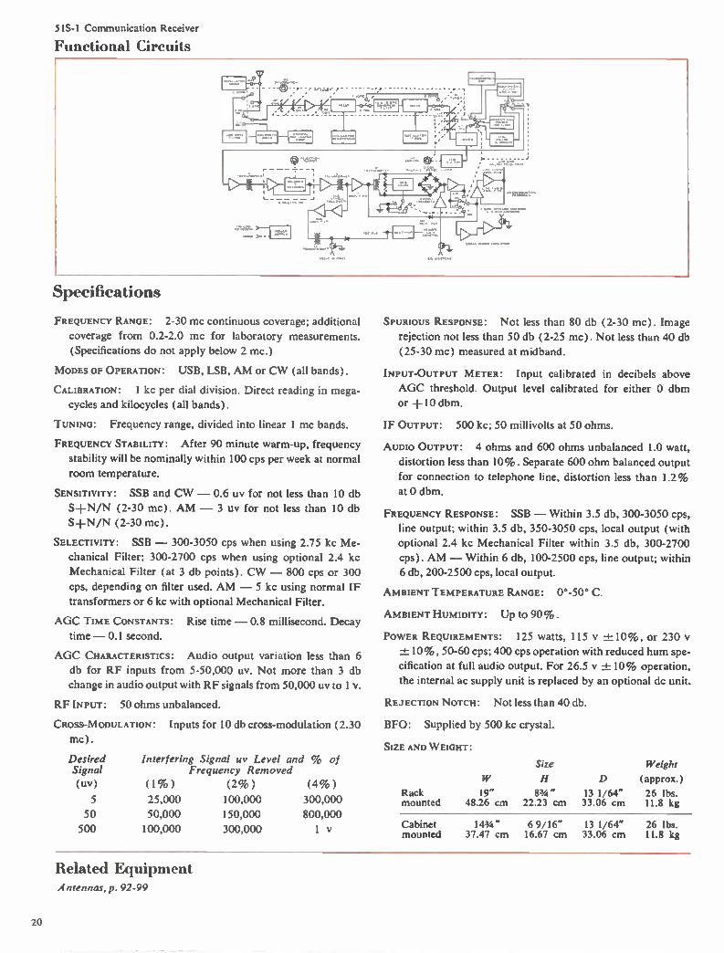
51S-1 Communication Receiver
Functional Circuits
Specifications
FREQUENCY RANGE: 2-30 mc continuous coverage; additional
coverage from 0.2-2.0 mc for laboratory measurements.
(Specifications do not apply below 2 mc.)
MODES OF OPERATION: USB, LSB, AM or CW (all bands).
CALIBRATION: I kc per dial division. Direct reading in mega-
cycles and kilocycles (all bands).
TUNING: Frequency range, divided into linear 1 mc bands.
FREQUENCY STABILITY: After 90 minute warm-up, frequency
stability will be nominally within 100 cps per week at normal
room temperature.
SENSITIVITY: SSB and CW — 0.6 uy for not less than 10 db
SH-N/N (2-30 mc). AM — 3 uy for not less than 10 db
S±N/N (2-30 mc).
SELECTIVITY: SSB — 300-3050 cps when using 2.75 kc Me-
chanical Filter; 300-2700 cps when using optional 2.4 kc
Mechanical Filter (at 3 db points). CW — 800 cps or 300
cps, depending on filter used. AM — 5 kc using normal IF
transformers or 6 kc with optional Mechanical Filter.
AGC TIME CONSTANTS:
time — 0.1 second.
AGC CHARACTERISTICS:
Rise time — 0.8 millisecond. Decay
Audio output variation less than 6
db for RF inputs from 5-50,000 uy. Not more than 3 db
change in audio output with RF signals from 50,000 uy to 1 v.
RF INPUT: 50 ohms unbalanced.
CROSS-MODULATION: Inputs for 10 db cross-modulation (2.30
mc).
Desired Signal (uy)
5
50
500
Interfering Signal uy Level and % of Frequency Removed
(1%) (2%) (4%)
25,000 100,000 300,000
50,000 150,000 800,000
100,000 300,000 1 y
SPURIOUS RESPONSE: Not less than 80 db (2-30 mc). Image
rejection not less than 50 db (2-25 mc). Not less than 40 db
(25-30 mc) measured at midband.
INPUT-OUTPUT METER: Input calibrated in decibels above
AGC threshold. Output level calibrated for either 0 dbm
or +10 dbm.
IF OUTPUT: 500 kc; 50 millivolts at 50 ohms.
AUDIO OUTPUT: 4 ohms and 600 ohms unbalanced 1.0 watt,
distortion less than 10% . Separate 600 ohm balanced output
for connection to telephone line, distortion less than 1.2%
at 0 dbm.
FREQUENCY RESPONSE: SSB — Within 3.5 db, 300-3050 cps,
line output; within 3.5 db, 350-3050 cps, local output (with
optional 2.4 kc Mechanical Filter within 3.5 db, 300-2700
cps). AM — Within 6 db, 100-2500 cps, line output; within
6 db, 200-2500 cps, local output.
AMBIENT TEMPERATURE RANGE: 0°-50° C.
AMBIENT HUMIDITY: Up to 90%.
POWER REQUIREMENTS: 125 watts, 115 y ± 10% , or 230 v
± 10%, 50-60 cps; 400 cps operation with reduced hum spe-
cification at full audio output. For 26.5 y ±10% operation,
the internal ac supply unit is replaced by an optional dc unit.
REJECTION NOTCH: Not less than 40 db.
BFO: Supplied by 500 kc crystal.
SIZE AND WEIGHT:
Rack mounted
19" 48.26 cm
Size
H
83/4 " 22.23 cm
13 1/64" 33.06 cm
Weight
D (approx.)
26 lbs. 11.8 kg
Cabinet 143/4 " 6 9/16" 13 1/64" 26 lbs. mounted 37.47 cm 16.67 cm 33.06 cm 11.8 kg
Related Equipment Antennas, p. 92-99
20
651F-1 universal radio group Receiver
Features
Automatic Tuning
Compact Packaging
Telephone Compatibility
Installation Flexibility
Remote Operation
Applications
Fixed Station
Transportable
Shipboard
Mobile
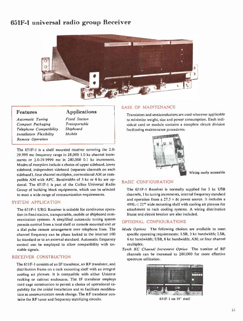
The 651F-1 is a shelf mounted receiver covering the 2.0-
29.999 mc frequency range in 28,000 1.0 kc channel incre-
ments or 2.0-29.9999 mc in 280,000 0.1 kc increments.
Modes of reception include a choice of upper sideband, lower
sideband, independent sideband (separate channels on each
sideband), four channel multiplex, conventional AM or com-
patible AM with AFC. Bandwidths of 3 kc or 6 kc are op-
tional. The 651F-1 is part of the Collins Universal Radio
Group of building block equipments, which can be selected
to meet a wide range of communication requirements.
SYSTEM APPLICATION
The 651F-1 URG Receiver is suitable for continuous opera-
tion in fixed station, transportable, mobile or shipboard com-
munication systems. A simplified automatic tuning system permits control from a local shelf or console mounted unit or
a dial pulse remote arrangement over telephone lines. The
channel frequency can be phase locked to the internal 100
kc standard or to an external standard. Automatic frequency
control can be employed to allow compatibility with un-
stable signals.
RECEIVER CONSTRUCTION
The 651F-1 consists of an IF translator, an RF translator, and
distribution frame on a rack mounting shelf with an integral
cooling air plenum. It is compatible with either Unistrut
racking or cabinet enclosures. The IF translator employs
card cage construction to permit a choice of operational ca-
pability for the initial installation and to facilitate modifica-
tion as communication needs change. The RF translator con-
tains the RF tuner and frequency stabilizing circuits.
EASE OF MAINTENANCE
Transistors and semiconductors are used wherever applicable
to minimize weight, size and power consumption. Each indi-vidual card or module contains a complete circuit division
facilitating maintenance procedures.
Wiring easily accessible
BASIC CONFIGURATION
The 651F-1 Receiver is normally supplied for 3 kc USB
channels, 1 kc tuning increments, internal frequency standard
and operation from a 27.5 y dc power source. It includes a
499L-1 22" wide mounting shelf with cooling air plenum for
attachment to rack cooling systems. A wiring distribution
frame and circuit breaker are also included.
OPTIONAL CONFIGURATIONS
Mode Options The following choices are available to meet
specific operating requirements: LSB, 3 kc bandwidth; LSB,
6 kc bandwidth; USB, 6 kc bandwidth; AM; or four channel
multiplex.
Tenth KC Channel Increment Option The number of RF
channels can be increased to 280,000 for more effective
spectrum utilization.
651F-1 on 19" shelf
21
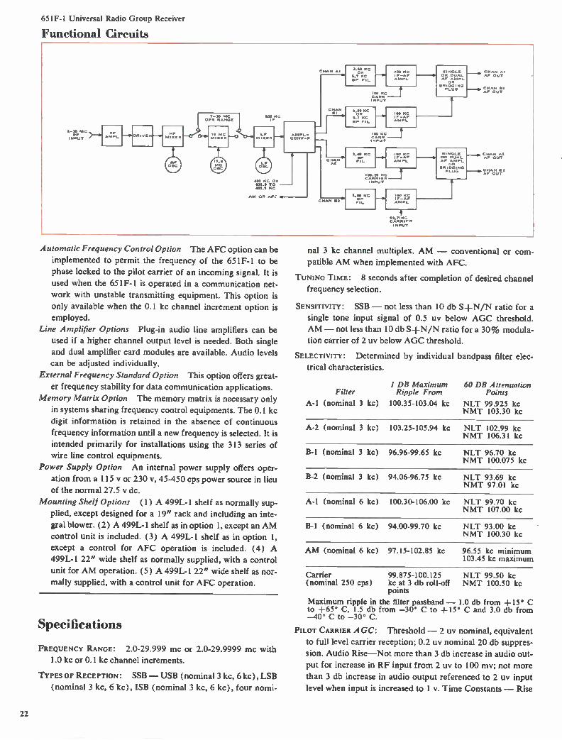
651F-1 Universal Radio Group Receiver
Functional Circuits
-111d DR I VE 1511-*4
,_47,1 OP 14 RANG
500 MC
400 KC OR 400.0 TO 400.9 KC
AM OR AFC 4
10 100 KC I F -AF 4 M PL
100 K CARR INPUT
CHAN BI
r- e11
2.66 KC OR
5.7 KC BP F1L
1,00 KC
45171111'-'
100 .c----T ----
CARR INPUT
2.69 KC BP F IL
100 KC 1F-AF AMPL
106. 19 CARRIER 1 NPUT
CHAN e2
2.69 KC I-411
100 K5
M PL
AF AM PL
BR IDGI NG PLuG
S I NGLE
2; BR In NG PLUG
93.710C CARR IF R INPUT
- C H 44 AI BP OUT
- CHAN *2
Automatic Frequency Control Option The AFC option can be
implemented to permit the frequency of the 651F-1 to be
phase locked to the pilot carrier of an incoming signal. It is
used when the 651F-1 is operated in a communication net-
work with unstable transmitting equipment. This option is
only available when the 0.1 kc channel increment option is
employed.
Line Amplifier Options Plug-in audio line amplifiers can be
used if a higher channel output level is needed. Both single
and dual amplifier card modules are available. Audio levels
can be adjusted individually.
External Frequency Standard Option This option offers great-
er frequency stability for data communication applications.
Memory Matrix Option The memory matrix is necessary only
in systems sharing frequency control equipments. The 0.1 kc
digit information is retained in the absence of continuous
frequency information until a new frequency is selected. It is
intended primarily for installations using the 313 series of
wire line control equipments.
Power Supply Option An internal power supply offers oper-
ation from a 115 y or 230 v, 45-450 cps power source in lieu
of the normal 27.5 y dc.
Mounting Shelf Options (1) A 499L-1 shelf as normally sup-
plied, except designed for a 19" rack and including an inte-
gral blower. (2) A 499L-1 shelf as in option 1, except an AM
control unit is included. (3) A 499L-1 shelf as in option 1,
except a control for AFC operation is included. (4) A
499L-1 22" wide shelf as normally supplied, with a control
unit for AM operation. (5) A 499L-1 22" wide shelf as nor-
mally supplied, with a control unit for AFC operation.
Specifications
FREQUENCY RANGE: 2.0-29.999 mc or 2.0-29.9999 mc with
1.0 kc or 0.1 kc channel increments.
TYPES OF RECEPTION: SSB - USB (nominal 3 kc, 6 kc), LSB
(nominal 3 kc, 6 kc), ISB (nominal 3 kc, 6 kc), four nomi-
nal 3 kc channel multiplex. AM - conventional or com-
patible AM when implemented with AFC.
TUNING TIME: 8 seconds after completion of desired channel
frequency selection.
SENSITIVITY: SSB - not less than 10 db S-l-N/N ratio for a
single tone input signal of 0.5 uy below AGC threshold.
AM - not less than 10 db S±N/N ratio for a 30% modula-
tion carrier of 2 uy below AGC threshold.
SELECTIVITY: Determined by individual bandpass filter elec-
trical characteristics.
I DB Maximum 60 DB Attenuation Filter Ripple From Points
A-1 (nominal 3 kc) 100.35-103.04 kc NLT 99.925 kc NMT 103.30 kc
A-2 (nominal 3 kc) 103.25-105.94 kc NIT 102.99 kc NMT 106.31 kc
B-1 (nominal 3 kc) 96.96-99.65 kc NLT 96.70 kc NMT 100.075 kc
B-2 (nominal 3 kc) 94.06-96.75 kc NLT 93.69 kc NMT 97.01 kc
A-1 (nominal 6 kc) 100.30-106.00 kc NLT 99.70 kc NMT 107.00 kc
B-1 (nominal 6 kc) 94.00-99.70 kc NLT 93.00 kc NMT 100.30 kc
AM (nominal 6 kc) 97.15-102.85 kc 96.55 kc minimum 103.45 kc maximum
Carrier (nominal 250 cps)
Maximum ripple in to +65° C, 1.5 db -40° C to -30° C.
99.875-100.125 NLT 99.50 kc kc at 3 db roll-off NMT 100.50 kc points
the filter passband - 1.0 db from +15° C from -30° C to +15° C and 3.0 db from
PILOT CARRIER AGC: Threshold - 2 uy nominal, equivalent
to full level carrier reception; 0.2 uy nominal 20 db suppres-
sion. Audio Rise-Not more than 3 db increase in audio out-
put for increase in RF input from 2 uy to 100 mv; not more
than 3 db increase in audio output referenced to 2 uy input
level when input is increased to 1 v. Time Constants - Rise
22
651F-1 Universal Radio Group Receiver
time 0.1 second; decay time 1 second. Enabling Method —
A ground on the enable line. Level Control — Choice of three
levels. Two preset levels are available by individual enabling
commands; one preset continuously adjustable and one pre-
set adjustable in 3 db steps for a total of 30 db. Pilot carrier
amplifier is enabled automatically whenever one of the pilot
carrier presets is enabled. A third external control can be
used to continuously vary level from a remote position. (Re-
mote line operation is not terminated when one of the preset
levels is desired.)
AFC OPERATION: Carrier Sensitivity — AFC operation
is possible on pilot carrier signals in the range of 0.5 uy to
0.1 v. Carrier Selectivity and Acquisition — Control is possi-
ble on pilot carrier signals in the frequency range of ± 100
cps from dial frequency. Acquisition covers a ±50 cps fre-quency range and is attained in less than 10 seconds (1 sec-
ond typical). Manual acquisition provided for a z.t-. 1000 cps
frequency range.
Tracking Rate — Automatic frequency control will remain
locked on carrier frequencies which vary up to 10 cps/second
(30 cps/second typical).
Selectivity Range — Automatic frequency control is possible
on pilot carrier signals in the frequency range of ± 1000
cps from dial frequency.
Hold Time — Frequency is maintained within +10 cps for a
minimum of one minute after loss of input signal.
Locking Error — Lock is maintained within less than +1
cps of the received carrier frequency.
Carrier Loss Alarm — Carrier loss is indicated by a ground-
on-line command for operation of an external alarm when the
suppressed carrier fades to a level less than necessary for au-
tomatic frequency control.
Frequency Deviation Meter — External connections for a
0-100 ua meter provide indication of the frequency deviation
corrected by the AFC. The external meter should have two
ranges, 0-1000 cps and 0-100 cps, selected by external shunts.
FREQUENCY CONTROL: All injection sources except channel
A-2 and B-2 multiplex carriers are phase locked to the inter-
nal frequency standard (or to the external standard, if used).
FREQUENCY STABILITY: Internal Standard — 1 part in 10" per day due to aging; rms stability factor does not exceed 1 part
in 10m in any 10 minute period. Multiplex channels A-1 and
B-1 determined by reference sources; A-2 and B-2 have an
additional deviation of ± 2 cps.
Hum AND NOISE: SSB — At least 50 db below rated output.
AM — At least 40 db down. With Fl A noise weighting, at
least 60 db below rated output. SPURIOUS RESPONSE: At least 60 db below response to normal
inband signals.
HARMONIC DISTORTION: SSB — Not more than 1% (2000 uy
CW input, 1500 cps audio output). AM — Not more than
5% (2000 uv, 30% modulation at 1000 cps).
INTERMODULATION DISTORTION: All intermodulation prod-
ucts at audio output are not less than 40 db down from one of
two equal test signals applied to input terminals at 100 uy
level and at +10 dbm audio output level.
QUIETING: For each 10 db increase of input signal, the signal-
to-noise ratio will increase 10 ±1 db up to 30 db above AGC
threshold. Ultimate quieting at +50 db above AGC thresh-
old, at least 50 db.
INTERNAL SPURIOUS: Except for three LFO crossover fre-
quencies, which are not more than 3.0 uy equivalent; not
more than 0.5 uy equivalent at any other frequency.
IMAGE REJECTION: At least 60 db except 55 db at 200 kc
above or below dial frequency.
IF REJECTION: At least 90 db.
AUTOMATIC GAIN CONTROL: Threshold — SSB, 1 UV nominal;
AM, 2 uy nominal. Audio Rise — SSB, not more than 4 db increase in audio output when the RF input is increased from
threshold to 1 v; AM, not more than 6 db increase in audio
output when the RF input is increased from threshold to 100
mv. Time Constants — All times are referred to within 3 db
of equilibrium levels; SSB Voice, rise time 8 milliseconds,
decay time 0.15 second; SSB Data, rise time 0.2 second, de-
cay time 0.15 second; AM, rise and decay time 0.2 second. Control Method — Isolated individual channel control up to
a nominal 60 uy RF input signal with strongest signal channel
controlling common AGC stages above 60 uy signal.
RF INPUT: 0.5 uy to 1.0 y into nominal 50 ohms. AGC
threshold 1.0 uy nominal (2.0 uy on AM).
AF OUTPUT: —10 dbm nominal and can be internally ampli-
fied to +10 dbm nominal into 600 ohms for single tone input
above AGC threshold.
POWER REQUIREMENTS: 24.0-30.25 y dc (27.5 y nominal)
negative ground with no more than 1 I/ peak-to-peak, 200
watts maximum. Can be implemented for ac power, 115 y or
230 v, 45-450 cps.
SIZE: 22 5/16" W, 83/4 " H, 241/2" D (56.67 cm W, 22.23
cm H, 62.23 cm D), including shelf.
WEIGHT: 62 lbs. (28.12 kg), minimum implementation; 80
lbs. (36.29 kg), maximum implementation, including shelf.
Basic Units 789R-1 IF Translator, p. 88-90
618Z-4 RF Translator, p. 87
Related Equipment 313 Series Controls, p. 83-85
Racks and Cabinets, p. 91
Antennas, p. 92-99
635R-1 Bandpass Filter, p. 110, 111
635T-2 Bandpass Filter, p. 111, 112
635V-1 Bandpass Filter, p. 112
23
1
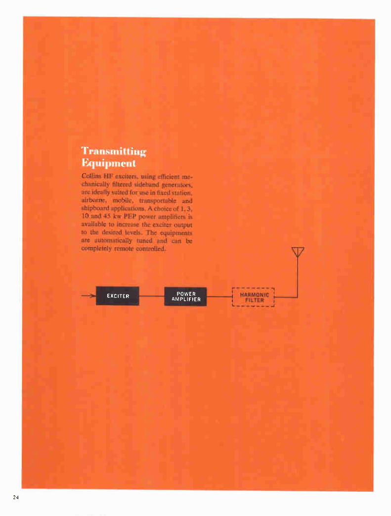
Transmitting Equipment Collins HF exciters, using efficient me-
chanically filtered sideband generators, are ideally suited for use in fixed station, airborne, mobile, transportable and shipboard applications. A choice of 1, 3, 10 and 45 kw PEP power amplifiers is
available to increase the exciter output to the desired levels. The equipments are automatically tuned and can be completely remote controlled.
POWER AMPLIFIER
r -, HARMONIC '
i FILTER i
24

310V-1 universal radio group Exciter
SYSTEM APPLICATION Features Automatic Tuning
Compact Packaging
Telephone Compatibility
Installation Flexibility
Remote Operation
Applications
Fixed Station
Transportable
Shipboard
Mobile
The 310V- l is a shelf mounted HF exciter which, together
with an automatically tuned power amplifier of the desired
level, provides an extremely versatile HF transmitter. It offers
a choice of 0.1 kc or 1.0 kc channel increments over the
2.0-29.9999 mc frequency range.
Modes of operation include upper sideband, lower sideband,
independent sideband (separate channels on each sideband),
or compatible AM with a choice of 3 kc or 6 kc bandwidths.
Four 3 kc SSB multiplex channels may be optionally used.
Power output is 0.4 watt PEP for continuous duty operation.
The 310V-1 is part of the Collins Universal Radio Group of
building block equipments, which can be selected to meet a
wide range of communication requirements.
310V-1 on 19" shelf
The 310V-1 is ideally suited for fixed station, transportable,
shipboard or mobile applications. A simplified automatic
tuning system permits control from a local shelf or console
mounted unit or by a dial pulse remote arrangement over
telephone lines. Audio terminations are compatible with tele-
phone industry standards.
EXCITER CONFIGURATION
The 310V- l consists of an IF translator, an RF translator,
and distribution frame on a rack mounting shelf with an in-
tegral cooling air plenum. It is compatible with either Uni-
strut racking or cabinet enclosures. The IF translator em-
ploys card cage construction to permit a choice of operational
capability for the initial installation and to facilitate modifi-
cation as communication needs change. The RF translator
contains the RF tuner and frequency stabilizing circuits.
FOUR CHANNEL MULTIPLEX
As many as four 3 kc bandwidth audio inputs can be multi-
plexed in the IF translator. The level of each individual chan-
nel is automatically adjusted according to the number in use.
ALC of the multiplex signal is provided by a bias from the
final stage of the associated power amplifier.
EASE OF MAINTENANCE
Transistors and semiconductors are used wherever applica-
ble to reduce size, minimize power consumption and increase
reliability. Each individual card or module contains a com-
plete circuit division, facilitating routine or corrective main-
tenance procedures.
BASIC CONFIGURATIONS
The 310V-1 Exciter is normally supplied for 3 kc USB chan-
nels, 1 kc tuning increments, operation from an internal fre-
25
310V-1 Universal Radio Group Exciter
quency standard and a 27.5 y dc power source. It includes a
499L-2 22" wide mounting shelf with a cooling air plenum
for attachment to rack cooling systems. A wiring distribution
frame and circuit breaker are also included.
OPTIONAL CONFIGURATIONS
Mode Options The following choices are available to meet
specific operating requirements: LSB, 3 kc bandwidth; LSB,
6 kc bandwidth; USB, 6 kc bandwidth; 4-channel multiplex;
and AM modes.
Tenth KC Channel Increment Option The number of RF
channels can be increased to 280,000 for more effective
spectrum utilization.
Line Amplifier Options Plug-in audio line amplifiers can be
used if the audio input level is below the required level. Both
single channel and dual channel amplifier card modules are
available. Individual level adjustments are provided.
External Frequency Standard Option This option offers great-
er frequency stability for data communication application.
Memory Matrix Option The memory matrix is necessary only
in systems sharing frequency control information between
equipments. In installations which share frequency control
equipment, the 0.1 kc digit information is retained in the ab-
sence of continuous frequency information until a new fre-
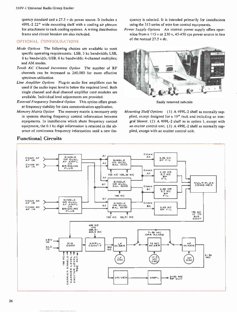
Functional Circuits
quency is selected. It is intended primarily for installations
using the 313 series of wire line control equipments.
Power Supply Options An internal power supply offers oper-
ation from a 115 y or 230 v, 45-450 cps power source in lieu
of the normal 27.5 y dc.
Easily removed subunits
Mounting Shelf Options (1) A 499L-2 shelf as normally sup-
plied, except designed for a 19" rack and including an inte-
gral blower. (2) A 499L-2 shelf as in option 1, except with
an exciter control unit. (3) A 499L-2 shelf as normally sup-
plied, except with an exciter control unit.
CHAN AI AF IN
CHAN BI AF IN
CHAN A2 AF IN
CHAN B2 AF IN
SINGLE OR DUAL AF A MP L
OR BRIDGING PLUG
KEY 1 N
ALC IN
AI
SI NGLE OR DUAL AF A MPL
OR B RI DG I NG PLUG
A2
Al
B I
B 1
SI NGLE OR DUAL BAL MOD
100
CHAN A2
KC 106.29 KC
SI NGLE OR DUAL BAL MOD
100 KC
SI NGLE OR DUAL BAL MOD
CHAN
AI
CHAN
B I
CHAN
B2
2.69 KC BP FIL
2.69 OR 5.7 KC BP FIL
2.69 OR 5.7 KC BP FIL
100 KC 93.71 KC
2.69 KC BP FIL
-^
MULTI PLEX COMB I NE R
100 KC IF TO SI G CONT
400 KC OR
400.0-400.9 KC
2-30 MC RF OUT
2-30 MC
26
310V-1 Universal Radio Group Exciter
Specifications
FREQUENCY RANGE: 2.0-29.999 mc or 2.0-29.9999 mc with
1.0 kc or 0.1 kc channel increments.
TRANSMISSION MODES: SSB — USB, LSB, ISB (3 kc or 6 kc
nominal bandwidths), or four nominal 3 kc channels multi-
plexed. AM — Compatible.
TUNING TIME: Not more than 8 seconds after selection of
frequency.
SELECTIVITY: Determined by individual bandpass filter elec-
trical characteristics.
I DB Maximum 60 DB Attenuation Filter Ripple From Points
A-1 (nominal 3 kc) 100.35-103.04 kc NLT 99.925 kc NMT 103.30 kc
A-2 (nominal 3 kc) 103.25-105.94 kc NLT 102.99 kc NMT 106.31 kc
B-1 (nominal 3 kc) 96.96-99.65 kc NLT 96.70 kc NMT 100.075 kc
B-2 (nominal 3 kc) 94.06-96.75 kc NLT 93.69 kc NMT 97.01 kc
A-1 (nominal 6 kc) 100.30-106.00 kc NLT 99.70 kc NMT 107.00 kc
B-1 (nominal 6 kc) 94.00-99.70 kc NLT 93.00 kc NMT 100.30 kc
Maximum ripple in the filter passband — 1.0 db from +15°C to +65° C; 1.5 db from —30°C to +15° C; 3.0 db from —40° to —30° C.
FREQUENCY CONTROL: All injection sources except A-2 and
B-2 carrier injection are phase locked to a 100 kc standard.
STABILITY: Internal standard — 1 part in 108 per day due to
aging; rms stability factor does not exceed 1 part in 108 in
any 10-minute period. Multiplex channels A- l and B-1 deter-
mined by reference source; channels A-2 and B-2 can have
an additional deviation of -± 2 cps.
RF OUTPUT: 0.4 watt PEP minimum into nominal 50 ohms.
OUTPUT DISTORTION: Third and higher order distortion prod-
ucts are suppressed at least 40 db below 0.4 watt PEP, meas-
ured by the standard two-tone test technique.
HARMONIC EmissioN: At least 50 db below nominal peak en-
velope voltage levels.
INTERMODULATION DISTORTION: Not less than 40 db down.
ADJACENT CHANNEL CROSS-TALK: Not less than 45 db down.
Hum: Not less than 50 db below one tone of a two-tone 0.4
watt PEP test signal.
SPURIOUS EMISSION: 40 db below nominal PEV.
TRANSMIT GAIN CONTROL: In response to dc levels of 4 V or
more derived from the output of the IF translator and the
output of the RF translator or power amplifier, an infinite
memory automatic gain control will maintain the dc levels
proportional within +1 db.
AUTOMATIC CHANNEL LOADING: Single or any combination
of channel inputs maintained at nominal input level will be
controlled automatically to permit minimal excursions above
nominal PEV level or operation into the ALC region.
AUDIO INPUT LEVEL: A —6 dbm, single tone input will pro-
duce maximum RF output with the exciter gain control full
on and no ALC/TGC input. Specified distortion characteris-
tics will be maintained with a two-tone input each having
—6 dbm level with ALC voltage applied to maintain output
level at 0.2 watt PEP. When implemented with the line am-
plifiers, tones at —26 dbm will meet the same specified output
requirements.
AUTOMATIC LOAD CONTROL: Input voltage in the range 0
to —10 y will cause the exciter output to be reduced at least
20 db. Minimum distortion requirements are met with up to
10 db reduction in gain. Application of ALC control will not
affect carrier output in the AM or reduced carrier modes and
will not affect the TGC.
POWER REQUIREMENTS: 24.0-30.25 y dc negative grounded
with no more than 0.5 I/ peak ripple, 170 watts nominal. Can
be implemented for 115 v, 45-450 cps.
SIZE: 22 5/16" W, 83/4 " H, 24 1/2 " D (56.67 cm W, 22.23
cm H, 62.23 cm D), including shelf.
W EIGHT: 62 lbs. (28.12 kg) minimum implementation; 80
lbs. (36.29 kg) maximum, including shelf.
Basic Units 789T-I IF Translator, p. 88-90
618Z-4 RF Translator, p. 87
Related Equipment Power Amplifiers, p. 28-37
426U-2 Power Supply, p. 86
313 Series Controls, p. 83-85
Racks and Cabinets, p. 91
Antennas, p. 92-99
635W-1 Harmonic Filter, p. 113
184U-10 RF Matrix Uniswitch, p. 106, 107
27
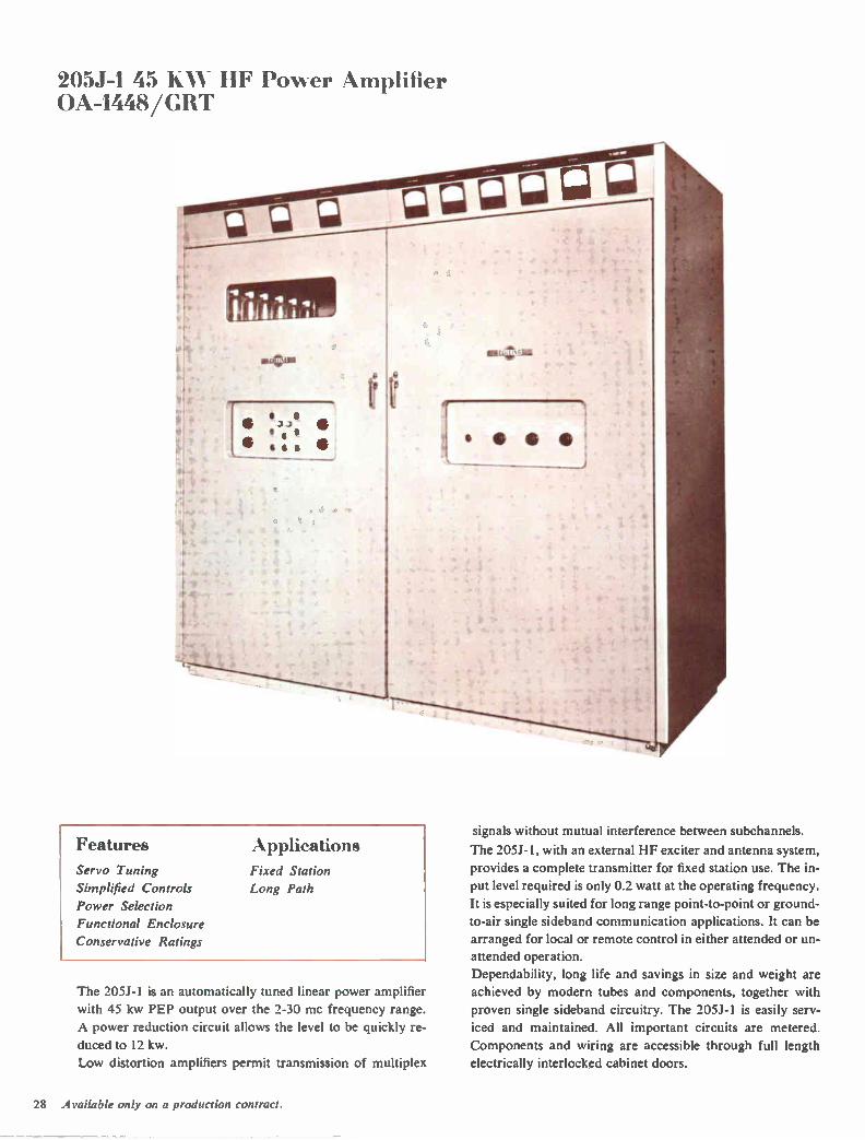
205J-I 45 KM HF Power Amplifier OA-1448/GRT
Features Applications Servo Tuning
Simplified Controls
Power Selection
Functional Enclosure
Conservative Ratings
Fixed Station
Long Path
The 205J-1 is an automatically tuned linear power amplifier
with 45 kw PEP output over the 2-30 mc frequency range.
A power reduction circuit allows the level to be quickly re-
duced to 12 kw.
Low distortion amplifiers permit transmission of multiplex
signals without mutual interference between subchannels.
The 205J-1, with an external HF exciter and antenna system,
provides a complete transmitter for fixed station use. The in-
put level required is only 0.2 watt at the operating frequency.
It is especially suited for long range point-to-point or ground-
to-air single sideband communication applications. It can be
arranged for local or remote control in either attended or un-
attended operation.
Dependability, long life and savings in size and weight are
achieved by modern tubes and components, together with
proven single sideband circuitry. The 205J-1 is easily serv-
iced and maintained. All important circuits are metered.
Components and wiring are accessible through full length
electrically interlocked cabinet doors.
28 Available only on a production contract.

205J-1 45 KW HF Power Amplifier
AUTOMATIC PLATE DISSIPATION CONTROL AUTOMATICALLY TUNED
RF and prepositioning information for the tuned circuits of
the power amplifier is supplied by an external exciter. Prepo-
sitioning information can also be obtained from an internal
control panel. Phase discriminator servo systems within the
equipment automatically complete the tuning and loading of
the three amplifier stages. A pi-L network is used for output
coupling. A directional coupler measures the forward and re-
flected power in the output transmission line.
LOW DISTORTION
Reduced distortion and improved linearity are achieved by
the use of approximately 10 db of negative over-all RF feed-
back in the power amplifier.
AUTOMATIC GAIN CONTROL
Transmitter gain control circuitry permits adjustment of the
signal level to operate the power amplifier near its maximum
power capability without the possibility of it being overdriven
on peaks. Rectified voltage derived from the signal peaks is
used to control circuitry in the associated exciter, reducing
the excitation level on signal peaks.
Design highlights
I. Separate shielded compartments for each RF stage.
2. Simplified operating controls are located on recessed panels.
3. Conservatively rated power supplies have excellent dynamic regulation.
4. Ceramic tetrode tubes provide high gain with few amplifier stages.
5. All components and wiring are ac-cessible through full length doors.
Automatic plate dissipation control circuits allow the power
amplifier to operate at full input during the tuning cycle and
remove the requirements of high/low power switching with
its accompanying problems.
CONSERVATIVELY RATED SUPPLIES
Efficient three-phase, full-wave rectifier circuits are used in
both plate and screen supplies. The screens of the tubes in the output stage are connected directly to ground to give maxi-
mum effectiveness to the screen grid shielding. The PA
cathodes are operated 700 y below ground, making the total
final amplifier plate supply voltage 7,500 v.
The negative side of the PA plate supply is grounded through
the primary of a thyratron trigger transformer. In the event
of a high voltage arc to ground, the initial surge of current in
the negative return fires a thyratron. This action effectively
shorts the high voltage supply to ground.
The low voltage plate and screen supply also use a three-
phase, full-wave rectifier. Mercury vapor rectifier tubes are
temperature-controlled allowing operation of the power am-
plifier at low ambient temperatures.
29
205J-1 45 KW HF Power Amplifier
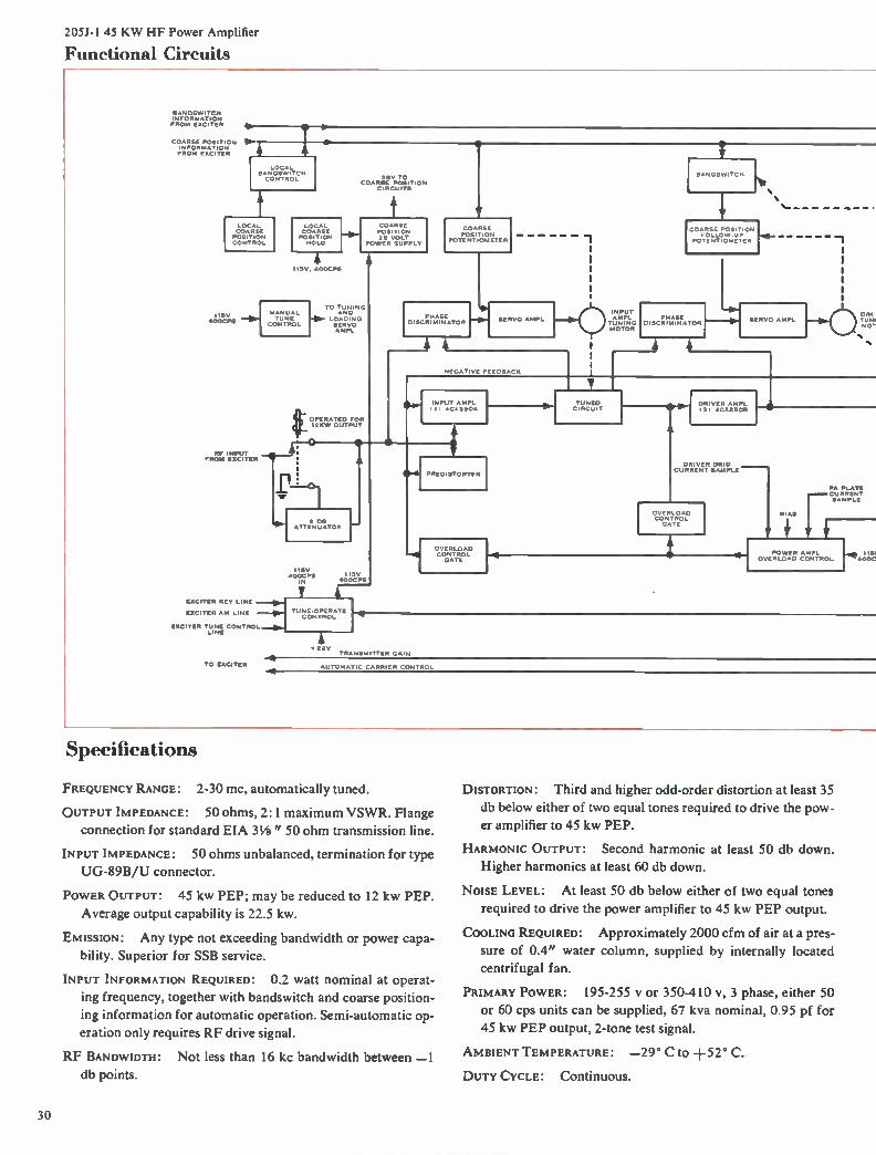
Functional Circuits
SANDSWITCH INFORMATION FROM EXCITER 4,
COARSE POSITION IN FROM EXCITER
LOCAL COARS POSITION CONTROL
LOCAL BANDSWITCH CONTROL
II5V ACKICPS
RF INPUT FROM EXCITER
LOCAL COARSE POSITION HOLD
II5V 400CPS
20V TO COARSE POSITION
CIRCUITS
COARSE POSITION 28 VOLT
POWER SUPPL
TO TUNING AND
LOADING SERVO AMPL
eOPERATED FOR I2KW OUTPUT
4-
COARSE POSITION
POTENTIOMETER
PHASE DISCRIMINATOR
SERVO AMPL
NEGATIVE FEEDBACK
1
INPUT AMPL TUNING MOTOR
BANDSW,TcH
COARSE POSITION FOLLOW LIP
POTENTIOMETER
PHASE DISCRIM/NATOR
INPUT AMPL .1 4C1(350A
115V 400CPS
ATTeNUTOR
II5V 400CPS
EXCITER KEY LINE
EXCITER AM LINE TUNE•OPERATE CONTROL
EXCITER TUNE CONTROL LINE
TO EXCITER
PRED .STORTER
OVERLOAD CONTROL GATE
TUNED CIRCUIT
SERVO AMPL
4
DRIVER AMPL .3 ACX25013
DRIVER GRID CURRENT
OVE LOAD CONTROL GATE
DRI TLIN. MO -
K.
K.
BIAS
PA PLATE
[CURRENT SAMPLE
POWER AMPL OVERLOAD CONTROL
F. 1151 400C
*28V TRANSMITTER GAIN
AUTOMATIC CARRIER CONTROL
Specifications
FREQUENCY RANGE: 2-30 RIC, automatically tuned.
OUTPUT IMPEDANCE: 50 ohms, 2:1 maximum VSWR. Flange
connection for standard EIA 3¼" 50 ohm transmission line.
INPUT IMPEDANCE: 50 ohms unbalanced, termination for type
UG-89B/U connector.
POWER OUTPUT: 45 kw PEP; may be reduced to 12 kw PEP.
Average output capability is 22.5 kw.
EMISSION: Any type not exceeding bandwidth or power capa-
bility. Superior for SSB service.
INPUT INFORMATION REQUIRED: 0.2 watt nominal at operat-
ing frequency, together with bandswitch and coarse position-
ing information for automatic operation. Semi-automatic op-
eration only requires RF drive signal.
RF BANDWIDTH: Not less than 16 kc bandwidth between —1 db points.
DISTORTION: Third and higher odd-order distortion at least 35
db below either of two equal tones required to drive the pow-
er amplifier to 45 kw PEP.
HARMONIC OUTPUT: Second harmonic at least 50 db down. Higher harmonics at least 60 db down.
NOISE LEVEL: At least 50 db below either of two equal tones
required to drive the power amplifier to 45 kw PEP output.
COOLING REQUIRED: Approximately 2000 cfm of air at a pres-
sure of 0.4" water column, supplied by internally located
centrifugal fan.
PRIMARY POWER: 195-255 y or 350-410 v, 3 phase, either 50
or 60 cps units can be supplied, 67 kva nominal, 0.95 pf for
45 kw PEP output, 2-tone test signal.
AMBIENT TEMPERATURE: —29° C to +52° C.
DUTY CYCLE: Continuous.
30
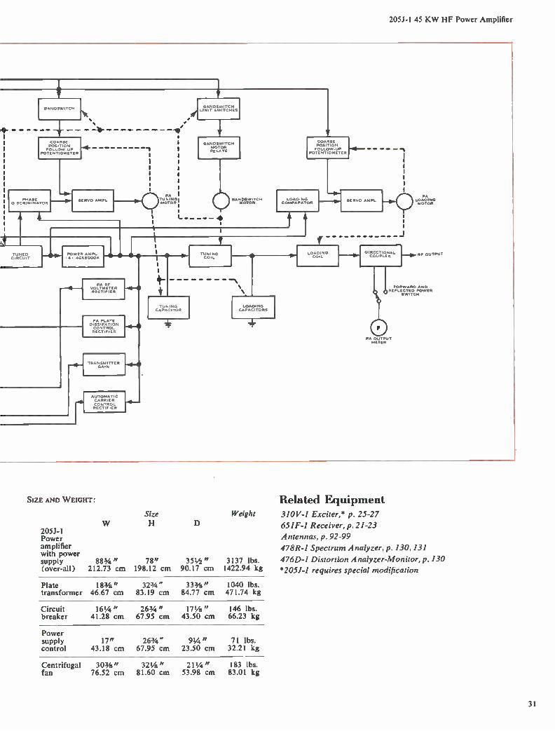
205J-1 45 KW HF Power Amplifier
BANDS ,,TcH
COARSE POSITION FOLLOW UP
POTENTIOMETER
-4.
PHASE DISCRIMINATO
SERVO AMPL
1
SANDSWITCH le LIMIT SWITCHES
BANDSWITCH MO OR RELAYS
PA TUNING1 BAN.DSr0 1,;ECH MOTOR . ,
TuNED CIRCUIT
POVvER AMPL ACX5000A
COARSE POSITION FOLLOW UP — — —
POTENTIOMETER
LOADING COMPARATOR
PA G F oie vOLTmFIETER RECTIFIER
PA PLATE D,SSiPAT1ON CONTROL RECTèFIER
HRANGSZN1TTER
AUTOMATiC CARRIER
TUNING C0,1_
SERVO AMP
APACITOR
—"\
LOADING CAPACITORS
LOADING COIL
Leae
1.111111e RF OUTPUT
FORWARD AHD 3 1) °REFLECTED POWER
SWITCH
PA OUTPUT METER
SIZE AND W EIGHT: Related Equipment Size Weight 310V-1 Exciter,* p. 25-27
W H D 651F-1 Receiver, p.21-23 205J-1 Power Antennas, p.92-99
amplifier 478R-1 Spectrum Analyzer, p. 130, 131 with power supply 883/4 " 78" 35 1/2 " 3137 lbs. 476D-1 Distortion Analyzer-Monitor, p. 130 (over-all) 212.73 cm 198.12 cm 90.17 cm 1422.94 kg *205.1-1 requires special modification
Plate 183/8" 323/4 " 33 3/8" 1040 lbs. transformer 46.67 cm 83.19 cm 84.77 cm 471.74 kg
Circuit 161/4 " 263/4 " 17 1/8" 146 lbs. breaker 41.28 cm 67.95 cm 43.50 cm 66.23 kg
Power supply 17" 263/4 " 91/4 " 71 lbs. control 43.18 cm 67.95 cm 23.50 cm 32.21 kg
Centrifugal 303/8" 321/8" 21 1/4 " 183 lbs. fan 76.52 cm 81.60 cm 53.98 cm 83.01 kg
31
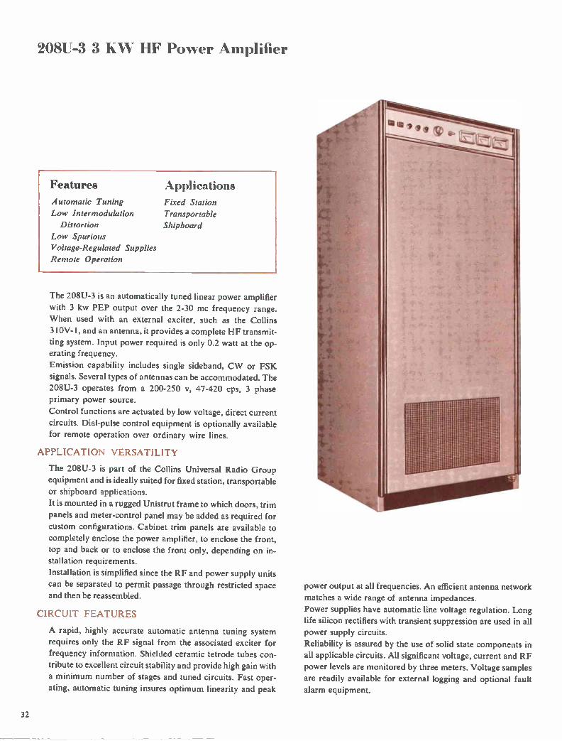
208U-3 3 10,% ELF Power Amplifier
Features
Automatic Tuning
Low Intermodulation
Distortion
Low Spurious
Voltage-Regulated Supplies
Remote Operation
Applications
Fixed Station
Transportable
Shipboard
The 208U-3 is an automatically tuned linear power amplifier
with 3 kw PEP output over the 2-30 mc frequency range.
When used with an external exciter, such as the Collins 310V-1, and an antenna, it provides a complete HF transmit-
ting system. Input power required is only 0.2 watt at the op-
erating frequency.
Emission capability includes single sideband, CW or FSK
signals. Several types of antennas can be accommodated. The 208U-3 operates from a 200-250 v, 47-420 cps, 3 phase
primary power source.
Control functions are actuated by low voltage, direct current
circuits. Dial-pulse control equipment is optionally available for remote operation over ordinary wire lines.
APPLICATION VERSATILITY
The 208U-3 is part of the Collins Universal Radio Group
equipment and is ideally suited for fixed station, transportable
or shipboard applications.
It is mounted in a rugged Unistrut frame to which doors, trim
panels and meter-control panel may be added as required for
custom configurations. Cabinet trim panels are available to
completely enclose the power amplifier, to enclose the front,
top and back or to enclose the front only, depending on in-stallation requirements.
Installation is simplified since the RF and power supply units
can be separated to permit passage through restricted space
and then be reassembled.
CIRCUIT FEATURES
A rapid, highly accurate automatic antenna tuning system
requires only the RF signal from the associated exciter for
frequency information. Shielded ceramic tetrode tubes con-
tribute to excellent circuit stability and provide high gain with
a minimum number of stages and tuned circuits. Fast oper-
ating, automatic tuning insures optimum linearity and peak
power output at all frequencies. An efficient antenna network
matches a wide range of antenna impedances.
Power supplies have automatic line voltage regulation. Long
life silicon rectifiers with transient suppression are used in all
power supply circuits.
Reliability is assured by the use of solid state components in
all applicable circuits. All significant voltage, current and RF
power levels are monitored by three meters. Voltage samples
are readily available for external logging and optional fault
alarm equipment.
32

208U-3 3 KW HF Power Amplifier
Functional Circuits
DPI
...el ____________ - •"' «ENLOE _ „.__,...P.
COIWitITTEN r CLOSED
CONTEL Er
'OPTIONAL', DORM. 00•ITSE POSITION
PEES 0IIICE
PHASE DISC»
'OS MOT
Pm/ SIE
DISC«
1010•011.101
IOC DC Mel
ONIKE
•ceIOOP
PIUS
COMM
LONDON, COUP
HH CUMENT SNIPE
TIZONACTI
esil Du, Cz1000P
CLEITIENT VON
PI. TE DISSIPET I ON L 'NIUE
Ut DETECT-
TIC DC TIC TOI
a MOVE DETECTOR ALAINA
OWECTIONAL COUPLER ASSUAN,
.--1 . 1EPLOCTIO PONES
POMPANO 'MOON
AL
IINCYONANO ANTENNA 1 SO 0.0à OUTPUT)
50' \Me
ANTINNA
NATTMITME
Specifications FREQUENCY RANGE: 2-30 mC.
POWER OUTPUT: 3 kw PEP or average.
DRIVE POWER: 0.2 watt PEP.
INPUT IMPEDANCE: 50 ohms.
OUTPUT IMPEDANCE: 50 ohms. Will accommodate up to 3:1
SWR. Will match at 32 ft. whip with accessory items.
OUTPUT INTERMoDULATION DISTORTION: Third and higher
order products at least 40 db below either of two equal test
tones which drive the power amplifier to rated output.
OUTPUT HARMONIC CONTENT: All harmonic output is not
less than 80 db below the fundamental power output meas-
ured on a 50 ohm load at any level up to rated power output.
TUNING TIME: Maximum, 10 seconds; nominal, 5 seconds.
Tune failure information is provided if equipment should
fail to tune within 15 seconds.
POWER SOURCE: 200-250 v, line to line, 3 phase, 47-420 cps.
A primary power regulator automatically maintains the input
voltage at 225 v.
POWER CONSUMPTION: Single tone CW at rated power, 7.5
kva. Two-tone at rated power, 4.3 kva. Power factor not less
than 0.9.
AMBIENT HUMIDITY: 0%-95%.
ALTITUDE: 0-10,000 ft. operating; 0-50,000 ft. nonoperating.
VIBRATION: 5-15 cps 0.03" double amplitude; 16-55 cps
0.02" double amplitude or 1 g, whichever is less.
SHOCK: Each individual unit (RF and power supply subunits),
when mounted in a suitable test frame, shall be capable of ac-
cepting 3 blows each direction in each of three planes for a
total of 18 blows and each impact shall be 15 g maximum, 11
milliseconds in duration.
SIZE: 31 9/16" W, 69" H, 223/4 " D (80.17 cm W , 175.26 cm
H, 56.83 cm D).
W EIGHT: Approx. 750 lbs. (340.2 kg).
Related Equipment 310V-1 Exciter, p. 25-27
313 Series Controls, p. 83-85
Antennas, p. 92-99
476D-1 Distortion Analyzer-Monitor, p. 130
478R-I Spectrum Analyzer, p. 130, 131
184U-10 RF Matrix Uniswitch, p. 106, 107
651F-I Receiver, p. 21-23
33

208U-10 10 KW Power Amplifier
Features Applications Automatic Tuning Fixed Station
Integral Shielding Transportable
Efficient Cooling Shipboard
Unattended Operation
Front Accessibility
Application Groups
The 208U- 10 is an automatically tuned, 10 kw HF linear
power amplifier which covers the 2-30 mc frequency range.
It will linearly amplify SSB, AM, CW, FSK or any other type
of signal within the specified bandwidth and power capabili-
ties. Tuning is normally completed within 10 seconds and
never exceeds 25 seconds. The 208U-10 will tune into a 50
ohm broadband antenna without an antenna coupler. Drive
power required from an associated exciter is only 0.2 watt
PEP. The 208U-10 is part of the Collins Universal Radio
Group equipment which can be selected to meet a wide
range of communication requirements.
The 208U-10 is equally well suited for fixed station, trans-
portable or shipboard installations. Heavy components are
mounted on a solid aluminum base-casting to give superior
structural characteristics under shock and vibration condi-
tions. The AN/TSC-38 HF Communication System is a typi-
cal transportable application of the 208U- 10 Power Ampli-
fier. Optional cabinet styles, cooling and input power require-
ments permit its use in a wide range of applications without
degradation of performance.
AUTOMATIC TUNING
A rapid, highly accurate automatic tuning system requires
only the RF signal from the associated exciter for frequency
information. Reliability is increased by the use of solid state
servo amplifiers.
CERAMIC TETRODE TUBES
Compact, well shielded ceramic tetrode tubes provide high
gain with a minimum number of stages and contribute to ex-
cellent circuit stability.
DC REMOTE CIRCUITS
Function control circuits employ low voltage direct current
and can be used with telephone type termination facilities
for unattended remote operation.
INTEGRAL SHIELDING
Very low conducted and radiated interference levels have
been achieved by the use of integral shielded compartments
and adequate filtering for each RF stage.
EXTENDED RELIABILITY
Simplified circuitry with a minimum number of stages and
tuned circuits increases reliability. Solid state components
are used wherever applicable to insure reliability. Long life
silicon rectifiers, together with efficient transient suppression
circuits, are employed in power supplies. All components are
rated for continuous operation at the highest specified tem-
peratures. A high capacity blower insures adequate cooling
even in high altitude environments.
CUSTOM CONFIGURATIONS
The 208U-10 is mounted in a rugged Unistrut frame with re-
movable exterior panels to facilitate use in custom configura-
tions and to simplify installation in transportable shelters or
in shipboard radio rooms. In shipboard applications the final
34
208U-10 10 KW HF Power Amplifier
RF amplifier can be separated from the power supply to fa-
cilitate handling through a restricted passage, and it can then
be quickly reassembled.
APPLICATION GROUPS
The following application groups are available: trim panels
for single or multiple installation, modified location of cool-
ing-air inlet and exhaust, a choice of primary power sources, automatic filament voltage regulation, primary power line
filters and automatic RF voltage control.
Trim Options The exterior cabinet panels and meter panel
snap or bolt on and can be installed initially or added later to
provide integrated styling with other related equipments.
Trim panels are not supplied with the basic power amplifier;
instead, optional application groups are selected to meet in-
dividual customer requirements.
Cabinet trim is available to completely enclose the power
amplifier, to enclose the front, top and back, or to enclose the
front only. Partial enclosure of the front, top and back is
for the middle units of a multiple power amplifier installa-
tion. The front trim group is for transportable hut or van
installations where the top, back and sides of the power am-
plifier are adjacent to other equipment, walls or ceiling.
Each of the trim groups is available with either a meter-con-
trol panel or a styled blank panel to complete the front enclo-
sure. The meter-control panel is for applications that require
local operational adjustments and power-level control, while
the blank panel is used in remotely controlled installations.
Cooling Air Options The 208U-10, as supplied, has a front air
inlet with filter and a top air outlet. A rear air intake applica-
tion group with external filtering is available for installations
where the ambient room air cannot be used for cooling. In
transportable installations with low ceilings, an application
group allows air to be exhausted from the top-rear without
extension of the power amplifier height.
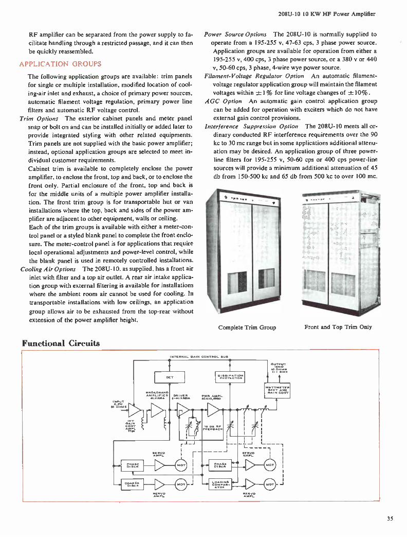
Functional Circuits
Power Source Options The 208U-10 is normally supplied to
operate from a 195-255 1/, 47-63 cps, 3 phase power source.
Application groups are available for operation from either a
195-255 v, 400 cps, 3 phase power source, or a 380 y or 440
v, 50-60 cps, 3 phase, 4-wire wye power source.
Filament-Voltage Regulator Option An automatic filament-
voltage regulator application group will maintain the filament
voltages within -± 1% for line voltage changes of -± 10 % .
AGC Option An automatic gain control application group
can be added for operation with exciters which do not have
external gain control provisions.
Interference Suppression Option The 208U-10 meets all or-
dinary conducted RF interference requirements over the 90
kc to 30 mc range but in some applications additional attenu-
ation may be desired. An application group of three power-
line filters for 195-255 v, 50-60 cps or 400 cps power-line
sources will provide a minimum additional attenuation of 45
db from 150-500 kc and 65 db from 500 kc to over 100 mc.
Complete Trim Group Front and Top Trim Only
INPUT 0.3W
50 OHMS
I NT GAI N COST
.. rTraL
INTERNAL GAIN CONTROL BUS
9
DEY
BROADBAND AMPLIFIER ACBMA
SERVO ANIPL
m‘e
DRIVE R 2-:1C X 350A
D I SSI PA TION PROTECTOR
PWR ANIPL ¿C St O. 000D
—É 15 DB RF FE E 1313ACIt
r -4
COARSE DISCR
SERVO AMPL
- -
PHASE DISCO
LOADING 0—
SE RVO AMPL
SE 13V0 AMP,-
OUTPUT 1010/1/
50 OHMS 3: I SWR
WATTMETER SECT. AND GAIN CONY
35

208U-10 10 KW HF Power Amplifier
Design highlights
! Centralized System Connections
2 Ceramic Tetrode Tubes
.3 Excellent RF Shielding
High Capacity Blower
Simplified Controls
f) Aluminum Base Casting
Specifications
FREQUENCY RANGE: 2-30 mc.
POWER OUTPUT: 10 kw PEP or average.
DRIVE POWER: 0.2 watt PEP.
INPUT IMPEDANCE: 50 ohms.
OUTPUT IMPEDANCE: 50 ohms, with up to 3:1 SWR (2.5-30.0
mc); 2:1 SWR (2.0-2.5 mc).
INTERMODULATION DISTORTION: All odd order distortion
products at least 35 db below one of two equal tones which
drive the power amplifier to 10 kw PEP.
HARMONIC CONTENT: Second harmonic at least 55 db down.
Higher order harmonics at least 60 db down.
TUNING TIME: Less than 25 seconds.
POWER CONSUMPTION: Single tone CW at rated power — 22
kva; two-tone test-20 kva. Power factor not less than 0.9.
POWER SOURCE: 195-255 y with 2% regulation, 47-63 cps, 3
phase. Taps provided for line voltage compensation. Avail-
able for operation from 380 y or 440 v, 50-60 cps, 4-wire wye
connection, or 200-250 v, 380-420 cps, 3 phase power
sources on special order.
AMBIENT HUMIDITY: 0%-95%.
ALTITUDE: 0-10,000 ft. operating; 0-50,000 ft. nonoperating.
VIBRATION: 5-15 cps 0.03" durable amplitude. 16-55 cps
0.02" double amplitude or 1 g whichever is less.
SHOCK: Each individual unit, when mounted in suitable test
frame, shall be capable of accepting 3 blows each direction in
each of 3 planes for a total of 18 shocks, and each impact in
the vertical plane shall be 30 g, 11 milliseconds in duration,
and each impact in the horizontal plane shall be 15 g, 11 milli-
seconds in duration.
SIZE: Without trim — 393/4 " W, 69" H, 27 1/4 " D (1.01 me-
ters W, 1.75 meters H, 0.69 meter D).
W EIGHT: Approx. 1650 lbs. (748.44 kg).
Related Equipment 310V-1 Exciter, p. 25-27
635W-1 Harmonic Filter, p. 113
313 Series Controls, p. 83-85
A ntennas, p.92-99
476D-1 Distortion A naly zer-M onit or , p. 130
478R-1 Spectrum Analyzer, p. 130, 131
184U-I 0 RF Matrix Uniswitch, p. 106, 107
651F-1 Receiver, p. 21-23
36

548L-4.1 KW HF Power Amplifier
Features
Automatic Tuning
Low Spurious
Compact Packaging
Maximum Accessibility
Applications
Fixed Station
Mobile
Transportable
Airborne
Shipboard
The 548L-4 is a compact power amplifier with a 1 kw PEP
or average output in the 2.0-29.9999 mc range.
It features automatic tuning, using tuning information in
0.1 kc increments. Tuning time is 2-3 seconds nominal, 10
seconds maximum.
Required drive is 0.2 watt PEP maximum on the channel
frequency. Over-all gain is within 3 db over the operating
range and within 1 db for a signal bandwidth of not less than
±7 kc of the center frequency. When used with an exciter,
such as the Collins 310V-1, and an antenna, it provides a
complete HF transmitter. The 548L-4 is part of the Collins
Universal Radio Group of building block equipments, which
can be selected to meet a wide range of communication sys-
tem requirements.
ADVANCED CIRCUITRY
The RF circuits consist of a two-stage amplifier with over-all
inverse feedback. Two 7551 tubes are used to drive four par-
allel 4CX350F's. The output passes through a directional
wattmeter circuit for transmission line VSWR indication.
FLEXIBLE INSTALLATION
The 548L-4 is housed in an ARINC 404 1 ATR size case
which can be easily mounted in a Unistrut or other type rack
for flexibility in configuration. Forced air cooling permits it
to be used over a wide range of ambient temperatures.
The 548L-4 Power Amplifier is equally applicable to fixed
station, shipboard, airborne and surface or air transportable
systems. It can be used in continuous duty applications with
either attended or unattended operation through local, re-
mote or telephone dial control. All frequency control func-
tions are accomplished by grounds on wires using a two-out-
of-five frequency code.
The 548L-4 is available with either an ac or dc power supply
and with or without a transmit-receive relay.
Functional Circuits
OR OR
r"- 71 ,7 ";;; L .r-117,r7;14 LR 1. 4 _< c SUPPLY I .
L - L.
IKW RF OUTPUT
Specifications
FREQUENCY RANGE: 2.0-29.9999 mc.
TUNING: Automatic, continuous coverage.
TYPES OF SIGNALS: Any, within bandwidth capability.
RF INPUT: 0.2 watt PEP maximum for rated PEP output.
TUNING TIME: Not more than 10 seconds maximum.
OUTPUT DISTORTION: Third and higher order distortion down
at least 35 db from either tone in a standard two-tone test.
HARMONIC EMISSION:
output level.
OUTPUT IMPEDANCE:
Suppressed at least 35 db below PEP
50 ohms unbalanced.
OUTPUT LEVEL:
input level.
1000 watts ±2 db PEP or average with rated
COOLING REQUIREMENTS: Forced air with 460 lbs. per hour at
1" water pressure minimum.
POWER REQUIREMENTS: 22.0-30.25 y dc (27.5 y nominal)
negative grounded with no more than 0.5 y ripple, 450 watts
standby and 3000 watts maximum keyed; also available for
operation with 120 y or 208 y power source, 400 cps, 3 phase.
SizE: 101/2 " W, 7% " H, 19 9/16" D (25.72 cm W, 19.37 cm
H, 49.69 cm D).
WEIGHT: 52 lbs. (23.6 kg).
Related Equipment
310V-I Exciter, p.25-27 Antennas, p. 92-99
426U-2 Power Supply, p. 86
37

A complete line of HF single sideband transceivers for both general purpose requirements and specialized needs is
available from Collins. Equipment for airborne, fixed station, mobile, trans-portable and military field pack applica-
tions is included. Each transceiver is especially designed for the intended en-vironment and will provide consistently high performance and reliability.
TRANSCEIVER
r 1
ANTENNA i COUPLER L _
38

32MS-1B 100 Watt Mobile Transceiver
Features
Four Pretuned Channels
Stable Signals
Simplified Controls
Power Source Options
Applications
Petroleum
Lumbering
Maritime Service
Highway Construction
Civil Defense
A ircraf t
Vehicle Fleet
The 32MS-1B Mobile Transceiver, with an output power of
100 watts PEP, provides SSB voice communication on four
channels which can be preset to any frequency in the
1.6-15.0 mc range. All functions, including pushbutton chan-
nel selection, are controlled from a small remote unit. The
32MS-1B is especially suited for use in private autos, trucks,
military vehicles, aircraft and marine installations.
SIMPLIFIED OPERATION
Proven SSB circuitry with a minimum number of controls fa-
cilitates use by nontechnical personnel. Each channel fre-
quency employs separate sets of inductors to insure optimum
selectivity.
Speech clipping is used on both positive and negative peaks to
provide increased effective modulation. RF feedback is used
in the RF amplifier section to maintain high linearity.
EASILY MAINTAINED
All tubes and controls for initial adjustments and tuning are
reached by removing the top and bottom cover. Tune-up re-
quires no external test equipment. The technician is not di-
rectly exposed to any high voltage circuits while maintaining
the equipment.
High stability frequency generation circuits, common to the
transmitter and receiver sections, simplify over-all circuitry
and operation, and insure transmission and reception of sig-
nals on identical frequencies, with no manual adjustment.
OPTIONAL POWER SUPPLY
Plug-in supplies permit operation from 12 y dc, 28 y dc or
115 y or 230 v, 50-400 cps, single phase sources, and facilitate
use of the 32MS-IB in land or maritime mobile, fixed station
or airborne applications.
ADEQUATE COOLING
The 32MS-1B is housed in a welded aluminum case. Cooling
is by convection. When transmitting, a blower forces air di-
rectly on the PA tubes and effects general air circulation
throughout the cabinet. Additional forced air can be employed in accordance with
ARINC standards for installations where normal ambient air
circulation is restricted.
39
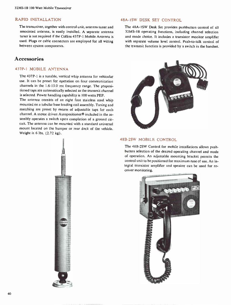
32MS-1B 100 Watt Mobile Transceiver
RAPID INSTALLATION
The transceiver, together with control unit, antenna tuner and
associated antenna, is easily installed. A separate antenna
tuner is not required if the Collins 437P-1 Mobile Antenna is
used. Plugs or cable connectors are employed for all wiring
between system components.
Accessories
437P-1 MOBILE ANTENNA
The 437P-1 is a tunable, vertical whip antenna for vehicular
use. It can be preset for operation on four communication channels in the 1.6-15.0 mc frequency range. The preposi-
tioned taps are automatically selected as the transmit channel
is selected. Power handling capability is 100 watts PEP.
The antenna consists of an eight foot stainless steel whip
mounted on a tubular base loading coil assembly. Tuning and
matching are preset by means of adjustable taps for each
channel. A motor driven Autopositionere included in the as-
sembly operates a switch upon completion of a ground cir-
cuit. The antenna can be mounted with a standard universal
mount located on the bumper or rear deck of the vehicle. Weight is 6 lbs. (2.72 kg).
48A-1SW DESK SET CONTROL
The 48A-1SW Desk Set provides pushbutton control of all 32MS-1B operating functions, including channel selection
and mode choice. It includes a transistor monitor amplifier
with separate volume level control. Push-to-talk control of
the transmit function is provided by a switch in the handset.
48B-2SW MOBILE CONTROL
The 48B-2SW Control for mobile installations allows push-
button selection of the desired operating channel and mode
of operation. An adjustable mounting bracket permits the
control unit to be positioned for maximum ease of use. An in-
tegral transistor amplifier and speaker can be used for re-
ceiver monitoring.
40
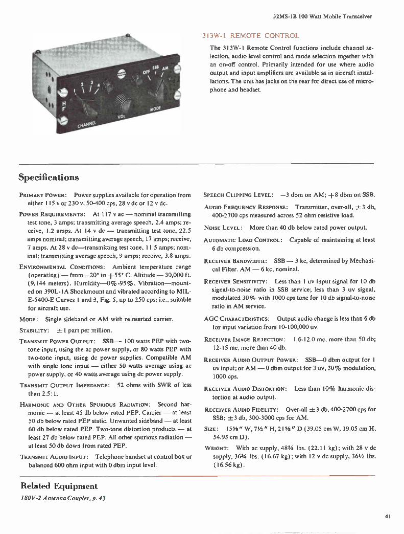
32MS-1B 100 Watt Mobile Transceiver
313W -1 REMOTE CONTROL
The 313W-1 Remote Control functions include channel se-
lection, audio level control and mode selection together with
an on-off control. Primarily intended for use where audio
output and input amplifiers are available as in aircraft instal-
lations. The unit has jacks on the rear for direct use of micro-
phone and headset.
Specifications
PRIMARY POWER: Power supplies available for operation from
either 115 y or 230 v, 50-400 cps, 28 v dc or 12 v dc.
POWER REQUIREMENTS: At 117 v ac — nominal transmitting
test tone, 3 amps; transmitting average speech, 2.4 amps; re-
ceive, 1.2 amps. At 14 y dc — transmitting test tone, 22.5
amps nominal; transmitting average speech, 17 amps; receive,
7 amps. At 28 y dc—transmitting test tone, 11.5 amps; nom-
inal; transmitting average speech, 9 amps; receive, 3.8 amps.
ENVIRONMENTAL CONDITIONS: Ambient temperature range
(operating) — from —20° to +55° C. Altitude — 30,000 ft.
(9,144 meters). Humidity-0% -95%. Vibration—mount-
ed on 390L-1A Shockmount and vibrated according to MIL-
E-5400-E Curves 1 and 3, Fig. 5, up to 250 cps; i.e., suitable
for aircraft use.
MODE: Single sideband or AM with reinserted carrier.
STABILITY: ± 1 part per million.
TRANSMIT POWER OUTPUT: SSB — 100 watts PEP with two-
tone input, using the ac power supply, or 80 watts PEP with
two-tone input, using dc power supplies. Compatible AM
with single tone input — either 50 watts average using ac
power supply, or 40 watts average using dc power supply.
TRANSMIT OUTPUT IMPEDANCE: 52 ohms with SWR of less
than 2.5: 1.
HARMONIC AND OTHER SPURIOUS RADIATION: Second har-
monic — at least 45 db below rated PEP. Carrier — at least
50 db below rated PEP static. Unwanted sideband — at least
60 db below rated PEP. Two-tone distortion products — at
least 27 db below rated PEP. All other spurious radiation —
at least 50 db down from rated PEP.
TRANSMIT AUDIO INPUT: Telephone handset at control box or
balanced 600 ohm input with 0 dbm input level.
SPEECH CLIPPING LEVEL: —3 dbm on AM; +8 dbm on SSB.
AUDIO FREQUENCY RESPONSE: Transmitter, over-all, ±3 db,
400-2700 cps measured across 52 ohm resistive load.
NOISE LEVEL: More than 40 db below rated power output.
AUTOMATIC LOAD CONTROL: Capable of maintaining at least
6 db compression.
RECEIVER BANDWIDTH: SSB — 3 kc, determined by Mechani-
cal Filter. AM — 6 kc, nominal.
RECEIVER SENSITIVITY: Less than 1 uy input signal for 10 db
signal-to-noise ratio in SSB service; less than 3 uy signal,
modulated 30% with 1000 cps tone for 10 db signal-to-noise
ratio in AM service.
AGC CHARACTERISTICS: Output audio change is less than 6 db
for input variation from 10-100,000 uy.
RECEIVER IMAGE REJECTION: 1.6-12.0 mc, more than 50 db;
12-15 mc, more than 40 db.
RECEIVER AUDIO OUTPUT POWER: SSB-0 dbm output for 1
uy input; or AM — 0 dbm output for 3 uy, 30% modulation,
1000 cps.
RECEIVER AUDIO DISTORTION: Less than 10% harmonic dis-
tortion at audio output.
RECEIVER AUDIO FIDELITY: Over-all -±3 db, 400-2700 cps for
SSB; ±3 db, 300-3000 cps for AM.
SizE: 153/8" W, 71/2 " H, 21341" D (39.05 cm W, 19.05 cm H,
54.93 cm D).
WEIGHT: With ac supply, 483/4 lbs. (22.11 kg); with 28 v dc
supply, 363/4 lbs. (16.67 kg); with 12 y dc supply, 36 1/2 lbs.
(16.56 kg).
Related Equipment
180V-2 Antenna Coupler, p. 43
41

32RS-1 100 Watt Transceiver
Features
Four Pretuned Channels
Stable Signals
Simplified Controls
Voice Operation (VOX)
Applications
Petroleum
Lumbering
Maritime Service
Highway Construction
Civil Defense
ining
Widespread Business
The 32RS-1 is a compact SSB voice transmitter-receiver for
fixed base industrial use. It has 100 watt PEP output on any
of four pretuned channels in the 1.6-15.0 mc frequency
range. Seven basic operating controls permit operation by
nontechnical personnel. A front panel meter indicates trans-
mitter output and incoming signal strength.
CIRCUIT FEATURES
Each communication channel employs separate sets of in-ductors to insure optimum frequency selectivity. RF feed-
back maintains high RF amplifier linearity. Automatic load
control circuitry provides a high level of "talking power" by
compensating for changes in voice levels. High stability fre-
quency generation circuits, common to both transmitter and
receiver, achieve circuit simplification and eliminate the
need for frequency trimming adjustments.
VOICE OPERATE CONTROL
An integral voice operated relay (VOX) automatically
switches the unit from receive function to transmit whenever
the operator speaks into the handset. If desired, VOX can be
over-ridden by depressing a push-to-talk button in the hand-
set or by grounding the key terminal.
The VOX control facilitates operation with ordinary tele-
phone extensions or through a telephone switchboard. An ac-
cessory "hybrid" termination unit is available for convenient
connection of the 32RS-1 Transceiver to existing 2-wire tele-
phone circuits.
EASY TUNE-UP
The panel meter can be employed for transmitter tuning
functions and a self-contained audio oscillator permits rapid
set up of new operating channels. All adjustments are con-
tinuous and the technician is protected from high voltage.
SIMPLE INSTALLATION
The 32RS- 1, together with associated antenna and optional
antenna tuner, is interconnected by plug-in cables. An ac-
cessory panel, located at the top of the transceiver, will ac-
commodate the 152J-1 Phone Patch or 302E-2 Directional
Wattmeter, as well as other switches and controls.
Accessories
302E-2 DIRECTIONAL WATTMETER
The 302E-2 can be mounted directly in the 32RS-1 acces-
sory panel. It can be easily removed for use at the antenna
site. A direct reading 0-200 watt scale indicates either for-
ward or reflected power.
Size: 5" W, 3" H, 5¼" D ( 12.7 cm W, 7.62 cm H, 13.34 cm
D). Weight: 3 lbs. (1.36 kg).
152J-1 PHONE PATCH
The 152J-1 uses a resistance hybrid circuit to match a 600
ohm telephone line to the unbalanced transmit and receive
audio terminations. It effectively isolates receiver and trans-
mitter functions.
When the phone patch is in operation, the 32RS- I handset is
left on its cradle and the station telephone is used. The line
42

32RS-1 100 Watt Transceiver
level is monitored using the station phone. A position is pro-
vided to "disconnect" the 32RS-1 when only telephone usage
is desired.
The station operator has complete supervisory control by
means of a switch which allows either transmit, receive or
VOX operation.
Size: 5" W, 3" H, 65/8" D (12.7 cm W, 7.62 cm H, 16.83 cm
D). Weight: 3 lbs. (1.36 kg).
180V-2 ANTENNA COUPLER
The 180V-2 will load single wire or whip antennas longer
than 50 ft. over the 1.6-15.0 mc range or longer than 30 ft.
over the 2.5-15.0 mc range. The circuit design is a modified
reversible "L" type matching network, which allows the use
of either low or high impedance antennas.
The 302E-2 Directional Wattmeter can be used directly at
the coupler site to facilitate adjustment for minimum re-
flected power. A remote key-switch allows operation of the
transmitter during tuning.
The 180V-2 is weatherproof. permitting installation at the
base of the antenna for maximum RF radiation efficiency.
Size: 12" W, 71/2 " H, 12" D (30.48 cm W, 19.05 cm H,
30.48 cm D). Weight: 15 lbs. (6.80 kg). 180V-2 Antenna Coupler
artimenit tosionflott;iilibtth
111 ..101%1111eXelOil:',VY'Cr
Specifications
GENERAL CHARACTERISTICS
FREQUENCY RANGE: 1.6-15.0 mc.
CHANNEL SELECTION: 4 crystal-controlled channels chosen
by channel selector switch.
FREQUENCY STABILITY: 1 part in 108 (0.0001%).
AMBIENT TEMPERATURE RANGE: —15° C to +55° C.
AMBIENT HUMIDITY RANGE: 0%-90%.
POWER SOURCE: 115 y or 230 v, 50-60 cps, single phase.
POWER REQUIREMENTS: 175 watts, receive only; 230 watts,
standby; 350 watts for full power transmit (average speech)
and 450 watts for full power transmit (2-tone test).
SIZE: 22" W, 241/2 " H, 143/4 " D (55.88 cm W, 62.23 cm H,
37.47 cm D).
WEIGHT: 97 lbs. (44 kg).
TRANSMITTING CHARACTERISTICS
POWER OUTPUT: 100 watts PEP.
OPERATING MODES: Either upper sideband or lower sideband
voice operation can be specified (USB is standard); R'TTY
by means of optional FSK keyer-converter.
OUTPUT IMPEDANCE: 52 ohms, capable of tuning a VSWR
of 2.5: I.
HARMONIC AND OTHER SPURIOUS SUPPRESSION: Carrier — at
least 50 db below peak output. Unwanted sideband — at
least 50 db below peak output. Second harmonic — at least
45 db below peak output into 52 ohm load. Spurious radia-
tion — 1.6-9.0 mc, down 60 db; 9-12 mc, down 45 db; 12-15
mc, transmit image down 40 db.
AUDIO INPUT: Telephone handset with provision for external
4-wire telephone connection, or with accessory hybrid, 2-
wire telephone connection.
OVER-ALL RESPONSE: zi_z 3 db, 350-3000 cps.
AUDIO FREQUENCY DISTORTION: Less than 6% with 100
watt PEP output.
AUTOMATIC LOAD CONTROL: Capable of at least 6 db com-
pression level.
RECEIVING CHARACTERISTICS
SELECTIVITY: 3 kc nominal, determined by the Mechanical
Filter.
SENSITIVITY: Less than 1 uy for 10 db signal-to-noise ratio.
IMAGE REJECTION: —50 db, 1.6-12.0 mc; —40 db, 12-13 mc;
—30 db, 13-15 mc.
AUDIO OUTPUT POWER: 2 watts maximum, undistorted. More
than 50 mw output for a 1 uy input signal, 1.6-12.0 mc.
More than 25 mw output for a 1 uy signal 12-15 mc.
OVER-ALL RESPONSE: ±3 db, 350-3000 cps.
RECEIVER DISTORTION: Less than 10% harmonic distortion
and —30 db intermodulation distortion at 0.5 watt audio
output level.
43

618T HF Transceiver including HF-I01, HF-102, HF-103, AN/ARC-94 and AN/ARC-IO2 Systems
Features Automatic Tuning
Frequency Accuracy
SELC A L Monitoring
Teletypewriter Capability
Modular Construction
Applications Airborne
Transportable
Mobile
Shipboard
Fixed Station
The 618T is a compact HF single sideband transceiver for
voice, CW, data or compatible AM communication in the
2.0-29.999 mc frequency range. It is automatically tuned in
28,000 1 kc channel increments by means of an operator's control unit.
The operating frequency is indicated directly in a digital-
type presentation. Nominal transmit power is 400 watts PEP in SSB or 100 watts in compatible AM.
APPLICATIONS
A choice of optional accessory antenna tuners permits its
use in a wide range of aircraft with peak performance at all
frequencies. A retrofit adapter is available to facilitate instal-
lation in an airframe which has been wired for a Collins 618S HF AM system.
The 618T, while primarily designed as an airborne trans-
ceiver, is ideally suited for transportable, mobile, shipboard
and semifixed station applications. Simplified automatic tun-
ing permits it to be operated by nontechnical personnel. In-
stant on-frequency operation is assured by a temperature-
compensated frequency standard with a stability of 0.8 part
per million per month.
Mission performance under a wide range of environments
has been greatly enhanced by an extensive reliability testing
program. It is housed in a 1 ATR case and weighs only 52
lbs., simplifying installation requirements.
DATA TRANSMISSION
For voice transmission, a very minute frequency error can
be allowed. Accurate reproduction of the transmitted fre-
quency components for data and signaling systems is either
unnecessary for 100 word per minute teletypewriters or can
be accommodated by accessory units. This concept results in
simplicity for the voice transceiver and adds automatic fre-
quency control complexity only when required by high speed
data systems.
SELECTIVE CALLING
The use of a selective calling (SELCAL) system on AM is
facilitated by a special audio output, which allows signals to be monitored regardless of the mode selection switch setting.
COOLING OPTIONS
Filtered air from a front panel blower is distributed to all
portions of the transceiver requiring forced air cooling. The
air is metered by vents of the proper size in the main chassis.
An exhaust port is provided for use with central cooling sys-
tems in accordance with ARINC Specification 404, if desired.
EASY MAINTENANCE
Low maintenance costs are achieved by the use of plug-in
modular assemblies. Transistor circuitry employed wherever
applicable results in a high degree of reliability, together with
minimum weight and power consumption.
TRANSCEIVER SYSTEMS
The 618T Transceiver is available in the following system
configurations for airborne applications:
HF-101 — 618T-1 Transceiver and 714E-2 Control with ex-
H • 0 2 . 0 '0 0 Al USA Lee m off DATA
c. RT SENS •t*.
7 14E-3 Control Unit
44
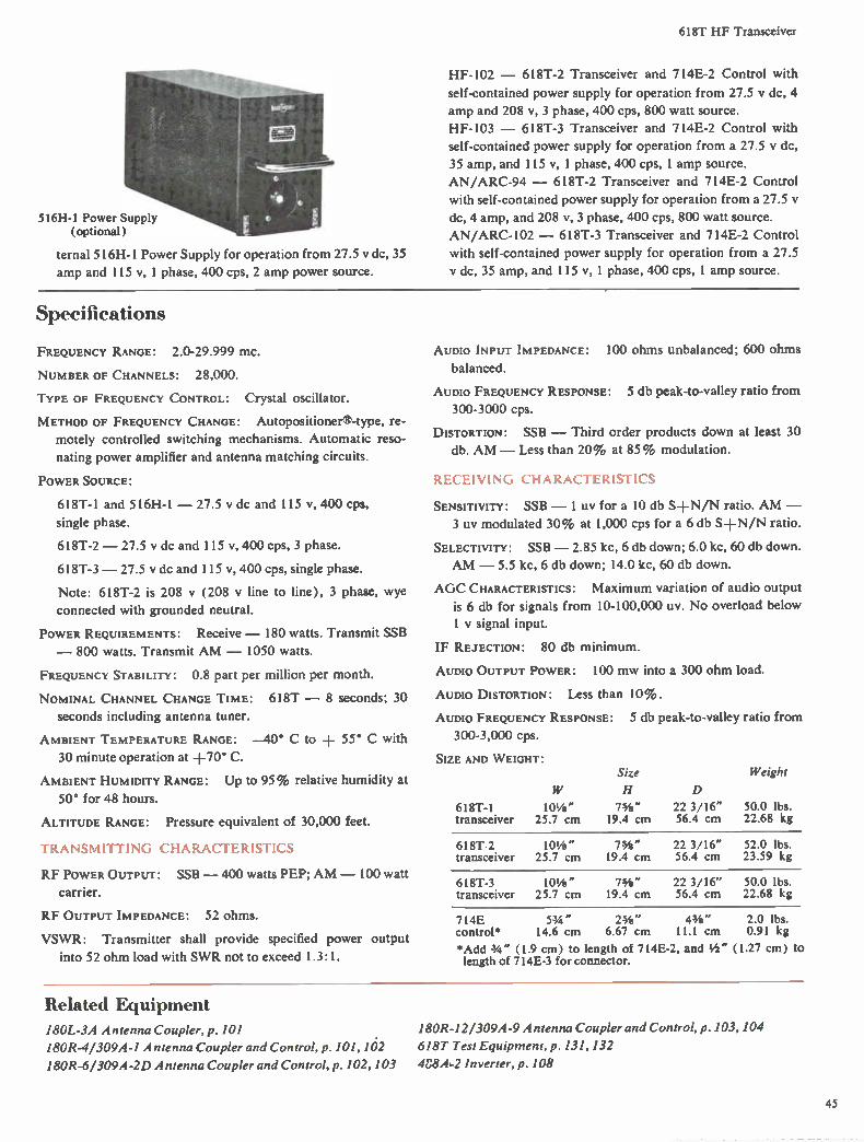
618T HF Transceiver
516H-1 Power Supply (optional)
ternal 516H-1 Power Supply for operation from 27.5 v dc, 35
amp and 115 v, 1 phase, 400 cps, 2 amp power source.
HF-102 - 618T-2 Transceiver and 714E-2 Control with
self-contained power supply for operation from 27.5 y dc, 4
amp and 208 v, 3 phase, 400 cps, 800 watt source.
HF-103 - 618T-3 Transceiver and 714E-2 Control with
self-contained power supply for operation from a 27.5 y dc,
35 amp, and 115 v, 1 phase, 400 cps, 1 amp source.
AN/ARC-94 - 618T-2 Transceiver and 714E-2 Control
with self-contained power supply for operation from a 27.5
dc, 4 amp, and 208 v, 3 phase, 400 cps, 800 watt source.
AN/ARC-102 - 618T-3 Transceiver and 714E-2 Control
with self-contained power supply for operation from a 27.5
dc, 35 amp, and 115 v, 1 phase, 400 cps, 1 amp source.
Specifications
FREQUENCY RANGE: 2.0-29.999 mc.
NUMBER OF CHANNELS: 28,000.
TYPE OF FREQUENCY CONTROL: Crystal oscillator.
METHOD OF FREQUENCY CHANGE: AUtOpOSitiOrler8-type, re-
motely controlled switching mechanisms. Automatic reso-
nating power amplifier and antenna matching circuits.
POWER SOURCE:
618T- l and 516H-1 - 27.5 v dc and 115 v, 400 cps,
single phase.
618T-2 - 27.5 v dc and 115 v, 400 cps, 3 phase.
618T-3 -27.5 y dc and 115 v, 400 cps, single phase.
Note: 618T-2 is 208 y (208 y line to line), 3 phase, wye
connected with grounded neutral.
POWER REQUIREMENTS: Receive - 180 watts. Transmit SSB
- 800 watts. Transmit AM - 1050 watts.
FREQUENCY STABILITY: 0.8 part per million per month.
NOMINAL CHANNEL CHANGE TIME: 618T - 8 seconds; 30
seconds including antenna tuner.
AMBIENT TEMPERATURE RANGE: -40° C to + 55° C with
30 minute operation at +70° C.
AMBIENT HUMIDITY RANGE: Up to 95% relative humidity at
50° for 48 hours.
ALTITUDE RANGE: Pressure equivalent of 30,000 feet.
TRANSMITTING CHARACTERISTICS
RF POWER OUTPUT: SSB -400 watts PEP; AM - 100 watt
carrier.
RF OUTPUT IMPEDANCE: 52 ohms.
VSWR: Transmitter shall provide specified power output
into 52 ohm load with SWR not to exceed 1.3:1.
AUDIO INPUT IMPEDANCE: 100 Ohms unbalanced; 600 ohms
balanced.
AUDIO FREQUENCY RESPONSE: 5 db peak-to-valley ratio from
300-3000 cps.
DISTORTION: SSB - Third order products down at least 30
db. AM - Less than 20% at 85% modulation.
RECEIVING CHARACTERISTICS
SENSITIVITY: SSB - 1 uy for a 10 db S+N/N ratio. AM -
3 uy modulated 30% at 1,000 cps for a 6 db S+N/N ratio.
SELECTIVITY: SSB - 2.85 kc, 6 db down; 6.0 kc, 60 db down.
AM - 5.5 kc, 6 db down; 14.0 kc, 60 db down.
AGC CHARACTERISTICS: Maximum variation of audio output
is 6 db for signals from 10-100,000 uy. No overload below
1 y signal input.
IF REJECTION: 80 db minimum.
AUDIO OUTPUT POWER: 100 mw into a 300 ohm load.
AUDIO DISTORTION: Less than 10%.
AUDIO FREQUENCY RESPONSE: 5 db peak-to-valley ratio from
300-3,000 cps.
SIZE AND WEIGHT: Size Weight
H D
618T-1 101/4 " 73/4 " 22 3/16" 50.0 lbs. transceiver 25.7 cm 19.4 cm 56.4 cm 22.68 kg
618T-2 101/4 " 73/4 " 22 3/16" 52.0 lbs. transceiver 25.7 cm 19.4 cm 56.4 cm 23.59 kg
618T-3 101/4 " 73/4 " 22 3/16" 50.0 lbs. transceiver 25.7 cm 19.4 cm 56.4 cm 22.68 kg
714E 53/4 " 23/4 " 43/4 " 2.0 lbs. control* 14.6 cm 6.67 cm 11.1 cm 0.91 kg
*Add 3/4 " (1.9 cm) to length of 714E-2, and 1/2 " (1.27 cm) to length of 714E-3 for connector.
Related Equipment
180L-3A Antenna Coupler, p. 101
180R-4/309A-1 Antenna Coupler and Control, p. 101, 102
180R-6/309A-2D A ntenna Coupler and Control, p. 102, 103
180R-12/309A-9 Antenna Coupler and Control, p. 103, 104
618T Test Equipment, p. 131, 132
4S8A.-2 Inverter, p. 108
45

671B-1 universal radio group Receiver-Exciter
Features Automatic Tuning
Installation Flexibility
Compact Packaging
Telephone Compatibility
Remote Operation
Applications Fixed Station
Transportable
Shipboard
Mobile
The 671B-1 is a shelf mounted receiver-exciter, covering the
2.0-29.9999 mc frequency range in either 28,000 1.0 kc or
280,000 0.1 kc channel increments. It is part of the Collins
Universal Radio Group of building block equipments which
can be selected to meet a wide range of communication re-
quirements. A complete HF transceiver consists of a 671B-1
and an automatically tuned linear amplifier of the desired
power level. Mode choice includes upper sideband, lower
sideband, or independent sideband with nominal 3 kc or 6
kc bandwidths. Compatible AM is available with 3 kc or 6 kc
bandwidth in transmit and 3 kc in receive.
SYSTEM APPLICATION
The URG receiver-exciter is suitable for continuous opera-
tion in fixed station, transportable or shipboard applications.
Either local or remote telephone-dial control systems can be
used. Audio terminations are compatible with telephone in-
dustry standards, allowing control of all necessary functions
over ordinary wire lines.
HIGH STABILITY
An internal frequency standard offers stability of one part
in 108 per day; however, an optional external standard is
available for applications which require extreme accuracy.
CONTROLS
A simplified control system uses ground-on-line command
in a two-out-of-five coding system for frequency selection.
EASE OF MAINTENANCE
Transistor and semiconductor circuitry is used wherever ap-
plicable to reduce size, minimize power consumption and in-
crease reliability. Unit construction and circuit modules per-
mit maximum accessibility for routine maintenance and sim-
plify spare parts logistics in larger communication systems.
Easily removed subunits
MECHANICAL CONFIGURATIONS
The basic receiver-exciter consists of an IF translator unit,
RF translator unit and mounting shelf.
The IF translator, containing the IF and audio circuits, em-
ploys card cage construction to permit a choice of modes and
audio requirements by plug-in circuit cards. This arrange-
ment also facilitates modification as communication needs
change. In receive, it converts the 500 kc signal from the RF
translator to audio, and functioning as an exciter, it converts
the audio input to a 500 kc signal for the RF translator.
The RF translator contains the RF tuner frequency generat-
ing circuits, frequency stabilization circuit, voltage regulator
and power supply. In receive function, the RF translator ac-
cepts the RF signal and converts it to the 500 kc frequency
required by the IF translator. As an exciter, it converts the
500 kc signal from the IF translator to the desired RF output
frequency. An integral mounting shelf with wiring distribu-
tion frame and a cooling air plenum is compatible with both
Unistrut racking and attractive cabinet enclosures. A modi-
fied shelf is also available for use in standard 19" racks.
BASIC CONFIGURATION
The 671B-1 is normally supplied with an internal frequency
standard, upper sideband 3 kc bandwidth and 1 kc RF chan-
nel increments for operation from a 27.5 y dc power source.
Also included is the 499L-3 Mounting Shelf with cooling air
plenum, distribution frame and circuit breaker.
46

671 B-1 Universal Radio Group Receiver-Exciter
OPTIONAL CONFIGURATIONS
Mode Options The following choices are available to meet
other specific operating requirements: LSB, 3 kc bandwidth;
LSB, 6 kc bandwidth; USB, 6 kc bandwidth; and AM.
Tenth KC Channel Increment Option The number of RF
channels can be increased to 280,000, allowing more effec-
tive utilization of the RF spectrum allocation.
Line Amplifier Options Plug-in audio line amplifiers can be
used on the incoming line in transmit and the audio output
in receive if higher levels are needed. Single input or output
line amplifiers for one channel systems, as well as dual ampli-
fiers for systems using channels on both USB and LSB, are
available.
External Frequency Standard Option This option offers ex-
tremely high frequency stability when a standard such as the
Collins 40N- l is used.
Functional Circuits
Memory Matrix Option The memory matrix is necessary only
in systems using 0.1 kc tuning option which share frequency
control information between equipments. The 0.1 kc digit
information is retained in the absence of continuous informa-
tion after tuning is completed until a new frequency is se-
lected. It is primarily intended for installations using the 313
series of wire line control equipments.
Power Supply Option An internal power supply enables oper-
ation from 115 y or 230 v, 45-450 cps power sources in lieu
of the standard 27.5 y dc.
Mounting Shelf Options A 499L-3 22" (55.25 cm) wide shelf
with distribution frame and local control unit and cooling air
plenum for central rack cooling; 499L-3 19" (48.34 cm)
wide shelf with distribution frame and blower in lieu of
plenum; or a 499L-3 19" (48.26 cm) wide shelf with distri-
bution frame, blower and control unit.
CHAH nl/AM
CNAN
AI IN
ete,
>-•
44_
011-9
100 KC F TM
SINGLE OR OUAL SAL MOO
100 KC
AMPL 100 KC
BRIT:LNG AMPLIFIER PLUG
<KAM
2,72e FIL
. 1
•-•
7-30 MC OPR RANGE
ORIVIER AIMPL 2-1,e,MC
Specifications
FREQUENCY RANGE: 2.0-29.999 mc or 2.0-29.9999 mc with
1.0 kc or 0.1 kc channel increments.
TYPES OF EMISSION: SSB — USB, LSB, ISB (3 kc or 6 kc
nominal bandwidths) or conventional AM in receive and
compatible AM in transmit.
TUNING TIME: Not more than 8 seconds after selection of
channel frequency.
STABILITY: Internal standard — 1 part in 108 per day due to
aging; rms stability factor does not exceed 1 part in 108 in any
10 minute period.
FREQUENCY CONTROL: All injection sources are phase locked
to an internal standard (or external standard, if used).
POWER REQUIREMENTS: 24.0-30.25 v dc negative ground with
no more than 0.5 y peak ripple; 170 watts nominal. Can be
implemented for 115 y or 230 v, 45-450 cps.
SELECTIVITY:
Filter
A-1 (nominal 3 kc)
-±1 DB Maximum Ripple From
100.35-103.04 kc
60 DB Attenuation Points
NLT 99.925 kc NMT 103.30 kc
B-1 (nominal 3 kc)
96.96-99.65 kc NLT 96.70 kc NMT 100.075 kc
A-1 (nominal 6 kc)
100.30-106.00 kc NLT 99.70 kc NMT 107.00 kc
B-1 (nominal 6 kc)
94.00-99.70 kc NLT 93.00 kc NMT 100.30 kc
AM (nominal 6 kc)
97.15-102.85 kc NLT 96.55 kc NMT 103:45 kc
Filter passband response — 1.0 db from +15° C to +65° C;
1.5 db from —30° C to +15° C; 3.0 db from —40° C to
—30° C.
47

671B-1 Universal Radio Group Receiver-Exciter
RECEIVING CHARACTERISTICS
RF INPUT: 0.5 UV ID 1 V.
AF OUTPUT: Nominal —10 dbm; can be amplified internally
to +10 dbm nominal into 600 ohms for single tone input
above AGC threshold.
SENSITIVITY: SSB — Not less than 10 db S-EN/N ratio for a
standard test signal of 0.5 us', single tone signal-on to signal-
off. AM — Not less than 10 db S±N/N ratio for a standard
30% modulated test signal of 2 uy, modulation-on to modu-
lation-off.
SPURIOUS RESPONSE: Not less than 60 db below response to
inband signals.
INTERMODULATION DISTORTION: All intermodulation prod-
ucts at audio output are not less than 40 db down from one
of two equal test signals applied to input terminals at 1000
uy level and at +10 dbm audio output level.
AUDIO OUTPUT: Nominal —10 dbm and can be amplified in-
ternally to +10 dbm with a single tone RF input above AGC
threshold. Optional +10 dbm line amplifiers when imple-
mented in IF translator.
Hum AND NOISE: For each 10 db increase of input signal the
S±N/N ratio increases 10 ± 1 db up to not less than 50 db
below rated SSB output and not less than 40 db below rated
AM output; with FIA noise filter weighting on SSB, not less
than 60 db below rated output.
HARMONIC DISTORTION: Not more than 1% (2000 UV CW
input, 1500 cps audio output).
AGC THRESHOLD: SSB — 1 uy nominal. AM — 2 uy nominal.
AGC AUDIO RISE: SSB — not more than 4 db increase in au-
dio output when the RF input is increased from threshold to
1 v. AM — not more than 6 db increase in audio output when
the RF input is increased from threshold to 200 mv.
AGC TIME CONSTANTS: All times are referred to within 3 db
of equilibrium levels. SSB — rise time 8 milliseconds; decay
time 0.15 second.
TRANSMITTING CHARACTERISTICS
RF OUTPUT: 0.4 watt PEP minimum.
AF INPUT: Test tone level — 26 dbm, nominal on 600 ohms
each channel; —6 dbm nominal on 600 ohms when not im-
plemented with line amplifiers. Voice —34 VU nominal each
channel; —14 VU when not implemented with line amplifiers.
CARRIER SUPPRESSION: Electrically controlled (both stepped
and continuous) from 0-30 db, below PEV as measured by
standard two-tone test; carrier leak suppression not less than
55 db in SSB.
HARMONIC EMISSION: At least 50 db below PEV level.
TRANSMIT GAIN CONTROL: In response to dc levels of 4 y or
more derived from the output of the IF translator and the
output of the RF translator or power amplifier, an infinite
memory AGC will maintain the dc levels proportional within
-±- 1 db by bias control of the RF translator gain.
Hum: Not less than 50 db below one tone of a two-tone 0.4
watt PEP test signal.
AUTOMATIC LOAD CONTROL: Input voltage in the range 0 to
—10 y will cause the exciter output to be reduced at least 20
db. Minimum distortion requirements are met with up to 10
db reduction in gain. Application of ALC will not affect car-
rier output in the AM or reduced carrier modes and will not
affect the TGC.
SPURIOUS EMISSIONS: 40 db below nominal PEV.
AUDIO INPUT: A-6 dbm, single tone input will produce max-
imum RF output with the exciter gain control full on and no
ALC/TGC input. Specified distortion characteristics are
maintained with a two-tone input each having —6 dbm level
with ALC voltage applied to maintain output level at 0.2 watt
PEP. ' /ith the addition of line amplifiers, tones at —26 dbm
will meet the same output requirements.
SIZE:
Cabinet shelf 21 3/4 " 55.25 cm
H D
91/2 " 23 1/2 " 24.13 cm 59.69 cm
Standard 19" shelf
19 1/32" 9 7/16" 48.34 cm 23.97 cm
25 9/16" 64.93 cm
W EIGHT: 72 lbs. (32.66 kg) minimum implementation; 95 lbs.
(43.09 kg) maximum implementation, including shelf.
Basie Units 789X-1 IF Translator, p. 88-90
618Z-4 RF Translator, p. 87
Related Equipment Power Amplifiers, p. 28-37
313 Series Controls, p. 83-85
Racks and Cabinets, p.91
48

AN/ARC-80 Airborne HF Communication S>stem
Amplifier Control RF Amplifier Transmitter
Pete" b're
Control Indicator
or.1 gift
Trailing Wire Antenna
Pilot Control
Features :Applications
Automatic Tuning Airborne
Data Capability
Frequency Calibration
Simplified Maintenance
Reduced Weight
The AN/ARC-80 HF Airborne Communication System is
especially suited for data handling. It consists of a transmit-
ter. RF amplifier, receiver, antenna coupler with shock-
mount, trailing wire antenna, amplifier control unit, and line
and harmonic filters. Mode and frequency selectors are on the
radio set control unit, while PA plate power and trailing wire
antenna controls are located on the control indicator unit.
The system provides I kc channel increments over the 2.0-
29.999 mc frequency range with 900 watts PEP output under
normal conditions.
Data communication can be used in upper sideband, lower sideband or independent sideband, and voice in upper side-
band mode. Other modes available with a minor change in
Zkif
rf
RF Filter
Receiver
Antenna Coupler
LP Filter Coupler Mount
the amplifier-control unit include CW, AM, FSK/teletype-
writer and voice on lower sideband.
Frequency variations can be adjusted to zero with a received
standard signal by means of a front panel control.
TRAILING WIRE ANTENNA AND
ANTENNA COUPLER
A trailing wire antenna is automatically positioned to the re-quired length for the frequency selected. It can be operated
at aircraft speeds up to 300 knots. The associated antenna
coupler requires no cooling in environments up to 55° C.
Forward and reflected output power is monitored by a meter
located on the control-indicator unit. Indicator lights denote
antenna wire torque limits. Interlocks prevent transmission at full power during tuning
cycle. The normal 30 second tuning sequence is indicated by a flashing lamp that remains lighted when tuning operation
is completed.
SIMPLIFIED INSTALLATION
Mounting plenums are available for the transmitter, RF am-
Available only on a production contract. 49

AN/ARC•80 Airborne HF Communication System
plifier, receiver group and the amplifier-control and any as-
sociated equipment. The mountings provide shock and vibra-
tion isolation together with distribution of cooling air to the
equipment. Cable ducts are included for installation of inter-
connecting wiring. These mounts are normally not supplied
with the AN/ARC-80 system but are available for custom
requirements.
M ODULAR CONSTRUCTION
The units employ modular construction to simplify mainte-
nance and to facilitate upgrading of the equipment as dic-
tated by future technical advances. Self-test and fault isola-
tion features permit monitoring of in-flight performance and
rapid determination of a malfunctioning unit or module.
CIRCUIT PROTECTION
Protective features include devices to guard against cooling
air loss, excessively high or low voltages, an open or short in
the RF amplifier output circuits, unretracted trailing wire
antennas as landing gear is lowered or landing hook is down,
and snagged antenna or loss of drogue. The antenna protec-
tive devices are optional.
Specifications
FREQUENCY RANGE: 2.0-29.999 mc.
NUMBER OF CHANNELS: 28,000.
MODES: LSB, USB, ISB, data and voice.
POWER REQUIREMENTS: 208 y, 380-420 cps, 3 phase, wye
connected. Standby - 609 va. Receive - 667 va continuous,
1069 va tune. Transmit - 2520 va continuous, 2626 va
tune. 25-29 y dc. Tune only - 15 amps. Antenna-jettison
only - 28 amps. Panel illumination - 5.0 y at 3 amps.
AMBIENT TEMPERATURE RANGE: Data mode - -12° C to
+55° C. Voice mode - -28° C to +55° C.
SERVICE CONDITIONS: MIL-E-5400.
ALTITUDE: 15,000 ft., operating; 50,000 ft., nonoperating.
TRANSMITTING CHARACTERISTICS
RF POWER OUTPUT: 900 watts PEP standard conditions; 800
watts, minimum power.
FREQUENCY STABILITY: 5 parts in 10"' per 7 hr. period.
AUDIO INPUT: 3.0 PEV, 600 ohms.
VOICE INPUT: 0.25 v, carbon microphone.
INTERMODULATION DISTORTION: 36 db below PEP.
SPURIOUS OUTPUT: 0.15-2.0 mc, +5 dbm; 2-40 mc, +17
dbm; 40-60 mc, -10 dbm; 60-100 mc, -5 dbm; 100-225 mc,
+5 dbm; 225-450 mc, -50 dbm; 450-1000 mc, -23 dbm.
RECEIVING CHARACTERISTICS
SENSITIVITY: 2 us' for 10 db S+N/N.
INTERMODULATION DISTORTION: 46 db below PEV.
FRONT END REJECTION: 80 db or greater.
AUDIO OUTPUT: 3 PEV, 600 ohms.
VOICE OUTPUT: 12 PEV, 600 ohms.
DYNAMIC RANGE: 100 db.
FREQUENCY STABILITY: 5 parts in 10" per 7 hr. period.
SIZE AND W EIGHT:
Unit Size H D
Weight
AM-3536/ 101/4 " 8 43/64" 20 25/64" 51 lbs. URC RF 27.62 cm 22.03 cm 51.79 cm 23.14 kg amplifier
R-1153/ URC receiver
101/4 " 8 43/64" 20 25/64" 401/2 lbs. 27.62 cm 22.03 cm 51.79 cm 18.38 kg
AM-3535 61/4 " 8 43/64" 20 25/64" 24 lbs. amplifier- 16.19 cm 22.03 cm 51.79 cm 10.89 kg control
AS-1331 14" 11" 50" 38 lbs. trailing 35.56 cm 27.94 cm 127.0 cm 17.24 kg wire antenna
CU-I094 71/2 " 8 11/32" 21 1/2 " 27 1/2 lbs. antenna 18.10 cm 21.20 cm 54.61 cm 12.47 kg coupler
T-899/ 107/3" 8 43/64" 20 25/64" 41 lbs. URC transmitter
27.62 cm 22.03 cm 51.79 cm 18.60 kg
C-4368 534" 21/4 " 4 13/16" 21/4 lbs. control 14.61 cm 6.67 cm 12.22 cm 1.02 kg unit
ID-1066 53/4 " 51/4 " 5 3/16" 3 lbs. control- 14.61 cm 13.34 cm 13.18 cm 1.36 kg indicator
F-775 RF 41/2 " 31/4 " 61/4 " 2 lbs. interference 11.43 cm 8.26 cm 15.88 cm 0.91 kg filter
F-776 10 3/16" 2" 4" 4 lbs. low-pass 25.88 cm 5.08 cm 10.16 cm 1.81 kg filter
MT-290 71/4 " 2" 17" 13/4 lbs. mounting, 18.10 cm 5.08 cm 43.18 cm 0.79 kg antenna coupler
50
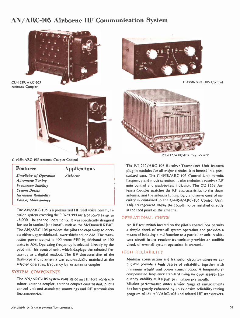
AN/ARC-105 Airborne HF Communication System
CU- 1239/ARC-105 Antenna Coupler
C-4959/ARC-I05 Antenna Coupler Control
Features Applications Simplicity of Operation Airborne
Automatic Tuning
Frequency Stability
System Design
Increased Reliability
Ease of Maintenance
The AN/ARC-105 is a pressurized HF SSB voice communi-
cation system covering the 2.0-29.999 mc frequency range in
28,000 1 kc channel increments. It was specifically designed for use in tactical jet aircraft, such as the McDonnell RF4C.
The AN/ARC-105 provides the pilot the capability to oper-
ate either upper sideband, lower sideband, or AM. The trans-
mitter power output is 400 watts PEP in sideband or 100
watts in AM. Operating frequency is selected directly by the
pilot with his control unit, which displays the selected fre-
quency as a digital readout. The RF characteristics of the
flush-type shunt antenna are automatically matched at the
selected operating frequency by an antenna coupler.
SYSTEM COMPONENTS
The AN/ARC-105 system consists of an HF receiver-trans-
mitter, antenna coupler, antenna coupler control unit, pilot's
control unit and associated mountings and RF transmission
line accessories.
C-4958/ARC-105 Control
•
RT-7 I 2/ ARC-105 Transceiver
The RT-712/ARC- 105 Receiver-Transmitter Unit features
plug-in modules for all major circuits. It is housed in a pres-
surized case. The C-4958/ARC-105 Control Unit permits
frequency and mode selection. It also includes a receiver RF
gain control and push-to-test indicator. The CU-1239 An-
tenna Coupler matches the RF characteristics to the shunt
antenna, and the antenna tuning logic and servo control cir-
cuitry is contained in the C-4959/ARC-105 Control Unit.
This arrangement allows the coupler to be installed directly
at the feed point of the antenna.
OPERATIONAL CHECK
An RF test switch located on the pilot's control box permits
a simple check of over-all system operation and provides a
means of isolating a malfunction to a particular unit. A side-
tone circuit in the receiver-transmitter provides an audible
check of over-all system operation in transmit.
HIGH RELIABILITY
Modular construction and transistor circuitry wherever ap-
plicable provide a high degree of reliability, together with
minimum weight and power consumption. A temperature-
compensated frequency standard using no oven assures fre-
quency stability at 0.8 part per million per month.
Mission performance under a wide range of environments
has been greatly enhanced by an extensive reliability testing
program of the AN/ARC-105 and related HF transceivers.
Available only on a production contract. 5 I
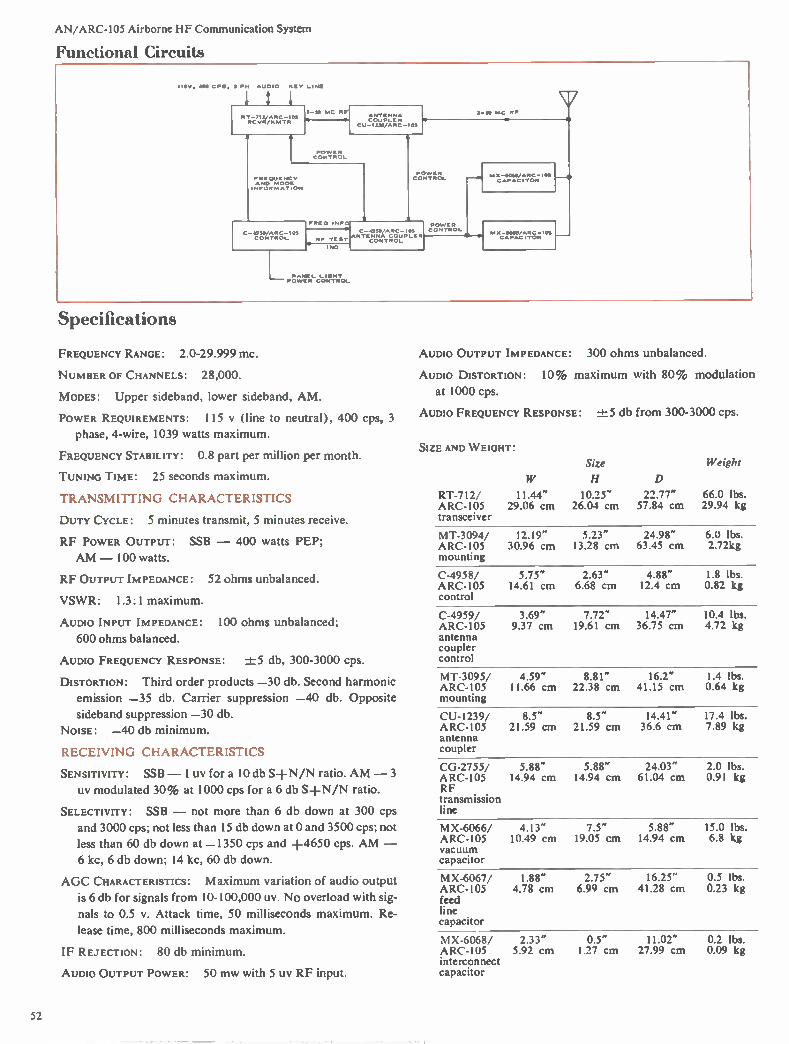
AN/ARC-105 Airborne HF Communication System
Functional Circuits
I I 5V . 400 CPS. 3 PH AUDIO KEY LI NE
1 R T-712,/ARC -1 05 RC VR/XINTR
2-30 MC RR
PO‘VE R CONTROL
tt1,1'V,ree, CU-I230/ARC- lo!
FREQUENCY AND MODE
I NFOR MATION
C.»49511/ARC -103 CONTROL
FRED I NF
Z-110 MC MF
POWER CONTROL
RF
o , ANT Eeetr.C.gt1 PLE R
NO
POWER CONTROL
M X-31065/ AR C - I OS H CAPACITOR
- CONTROL
"t,C7,S;'"H
Specifications
FREQUENCY RANGE: 2.0-29.999 mc.
NUMBER OF CHANNELS: 28,000.
MODES: Upper sideband, lower sideband, AM.
POWER REQUIREMENTS: 115 y (line to neutral), 400 cps, 3
phase, 4-wire, 1039 watts maximum.
FREQUENCY STABILITY: 0.8 part per million per month.
TUNING TIME: 25 seconds maximum.
TRANSMITTING CHARACTERISTICS
DUTY CYCLE: 5 minutes transmit, 5 minutes receive.
RF POWER OUTPUT: SSB - 400 watts PEP;
AM - 100 watts.
RF OUTPUT IMPEDANCE: 52 ohms unbalanced.
VSWR: 1.3:1 maximum.
AUDIO INPUT IMPEDANCE: 100 Ohms unbalanced;
600 ohms balanced.
AUDIO FREQUENCY RESPONSE: ±5 db, 300-3000 cps.
DISTORTION: Third order products -30 db. Second harmonic
emission -35 db. Carrier suppression -40 db. Opposite
sideband suppression -30 db.
NOISE: -40 db minimum.
RECEIVING CHARACTERISTICS CG-2755/ 5.88" 5.88" 24.03" 2.0 lbs.
SENSITIVITY: SSB - 1 uv for a 10 db S+N/N ratio. AM - 3 ARC-105 14.94 cm 14.94 cm 61.04 cm 0.91 kg uy modulated 30% at 1000 cps for a 6 db S+N/N ratio. RF
transmission SELECTIVITY: SSB - not more than 6 db down at 300 cps line
and 3000 cps; not less than 15 db down at 0 and 3500 cps; not MX-6066/ 4.13" 7.5" 5.88" 15.0 lbs. less than 60 db down at -1350 cps and +4650 cps. AM - ARC-105 10.49 cm 19.05 cm 14.94 cm 6.8 kg
vacuum 6 kc, 6 db down; 14 kc, 60 db down. capacitor
AUDIO OUTPUT IMPEDANCE: 300 ohms unbalanced.
AUDIO DISTORTION: 10% maximum with 80% modulation
at 1000 cps.
AUDIO FREQUENCY RESPONSE: ±5 db from 300-3000 cps.
SIZE AND WEIGHT:
Size
H D
Weight
RT-712/ 11.44" 10.25" 22.77" 66.0 lbs. ARC-105 29.06 cm 26.04 cm 57.84 cm 29.94 kg transceiver
MT-3094/ 12.19" 5.23" 24.98" 6.0 lbs. ARC-105 30.96 cm 13.28 cm 63.45 cm 2.72kg mounting
C-4958/ 5.75" 2.63" 4.88" 1.8 lbs. ARC-105 14.61 cm 6.68 cm 12.4 cm 0.82 kg control
C-4959/ 3.69" 7.72" 14.47" 10.4 lbs. ARC-105 9.37 cm 19.61 cm 36.75 cm 4.72 kg antenna coupler control
MT-3095/ 4.59" 8.81" 16.2" 1.4 lbs. ARC-105 11.66 cm 22.38 cm 41.15 cm 0.64 kg mounting
CU-I239/ 8.5" 8.5" 14.41" 17.4 lbs. ARC-105 21.59 cm 21.59 cm 36.6 cm 7.89 kg antenna coupler
AGC CHARACTERISTICS: Maximum variation of audio output
is 6 db for signals from 10-100,000 uy. No overload with sig-
nals to 0.5 v. Attack time, 50 milliseconds maximum. Re-
lease time, 800 milliseconds maximum.
IF REJECTION: 80 db minimum.
AUDIO OUTPUT POWER: 50 mw with 5 uy RF input.
MX-6067/ 1.88" 2.75" 16.25" 0.5 lbs. ARC-105 4.78 cm 6.99 cm 41.28 cm 0.23 kg feed line capacitor
MX-6068/ 2.33" 0.5" 11.02" 0.2 lbs. ARC-105 5.92 cm 1.27 cm 27.99 cm 0.09 kg interconnect capacitor

AN/PRC-38 40 Watt SSB-FM Man Pack Transceiver
COMMUNICATION COMPATIBILITY
Features Multimode Communication
Simplified Operation
Spectrum Utilization
HP/VHF/SSB or FM
Compatibility
Easily Maintained
Ápplications Man Pack
Vehicular
Aircraft
Shipboard
Setnifixed
The AN/PRC-38 is a man pack transceiver with 40 watts
PEP output and a choice of single sideband or FM modes in
the 20.0-69.99 mc frequency range. Suitable in man pack,
vehicular, aircraft, shipboard or semifixed station applica-
tions, it fulfills a distinct need for compatible SSB or FM
short range military communication. The number of avail-
able channels is increased tenfold using 7.5 kc SSB channels,
spaced 10 kc, compared with conventional FM.
Compatibility with currently used FM modes, as well as
SSB, permits routine communication with activities using
the following equipment: AN/ARC-44, AN/ARC-54, AN/
ARC-58, AN/ARC-94, AN/GRC-3, AN/GRC-5, AN/
GRC-7, AN/MRC-36, AN/MRC-37, AN/MRC-38, AN/
M RC-83, AN/MRC-87, AN/MRC-94, AN/MRC-95, AN/
PRC-8, AN/PRC-9, AN/PRC-10, AN/PRC-25, AN/TRC-
91, AN/TSC-15, AN/TSC-38, AN/URC-20, AN/URC-21,
AN/URC-32, AN/VRC-12 and other military communica-
tion equipment.
SIMPLIFIED OPERATION
A straightforward, digital-type tuning system, with a dial
that indicates frequency directly, reduces the possibility of
operator error. A unique frequency synthesis system gener-
Available only on a production contract. 53
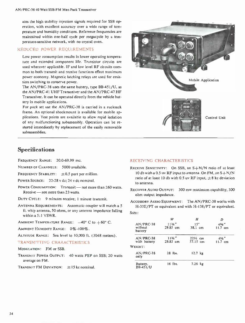
AN/PRC-3840 Watt SSB-FM Man Pack Transceiver
ates the high stability injection signals required for SSB op-
eration, with excellent accuracy over a wide range of tem-
perature and humidity conditions. Reference frequencies are
maintained within one-half cycle per megacycle by a tem-
perature-sensitive network, with no crystal oven.
REDUCED POWER REQUIREMENTS
Low power consumption results in lower operating tempera-
ture and extended component life. Transistor circuits are
used wherever applicable. IF and low level RF circuits com-
mon to both transmit and receive functions effect maximum
power economy. Magnetic latching relays are used for emis-
sion switching to conserve power.
The AN/PRC-38 uses the same battery, type BB-451/U, as
the AN/PRC-41 UHF Transceiver and the AN/PRC-47 HF
Transceiver. It can be operated directly from the vehicle bat-
tery in mobile applications.
For pack set use the AN/PRC-38 is carried in a rucksack
frame. An optional shockmount is available for mobile ap-
plications. Test points are available to allow rapid isolation
of any malfunctioning subassembly. Operation can be re-
stored immediately by replacement of the easily removable
subassemblies.
Mobile Application
Control Unit
Specifications
FREQUENCY RANGE: 20.0-69.99 MC.
NUMBER OF CHANNELS: 5000 available.
FREQUENCY STABILITY: -.±0.5 part per million.
POWER SOURCE: 22-28 y dc; 24 y de nominal.
POWER CONSUMPTION: Transmit — not more than 260 watts.
Receive — not more than 23 watts.
DUTY CYCLE: 9 minutes receive; 1 minute transmit.
ANTENNA REQUIREMENTS: Automatic coupler will match a 5
ft. whip antenna, 50 ohms, or any antenna impedance falling
within a 5:1 VSWR.
AMBIENT TEMPERATURE RANGE: —40° C to +60° C.
AMBIENT HUMIDITY RANGE: 0%-100%.
ALTITUDE RANGE: Sea level to 10,000 ft. (3048 meters).
TRANSMITTING CHARACTERISTICS
MODULATION: FM or SSB.
TRANSMIT POWER OUTPUT: 40 watts PEP on SSB; 20 watts
average on FM.
TRANSMIT FM DEVIATION: +15 kc nominal.
RECEIVING CHARACTERISTICS
RECEIVE SENSITIVITY: On SSB, an SH-N/N ratio of at least
10 db with a 0.5 uy RF input to antenna. On FM, an SH-N/N
ratio of at least 10 db with 0.5 uy RF input, -± 8 kc deviation
to antenna.
RECEIVER AUDIO OUTPUT: 300 MW maximum capability, 300
ohm output impedance.
ACCESSORY AUDIO EQUIPMENT: The AN/PRC-38 works with
H-33E/PT or equivalent and with H-138/PT or equivalent.
SIZE:
AN/PRC-38 without battery
11 3Zi" 29.85 cm
15" 38.1 cm
D
45/8" 11.7 cm
AN/PRC-38 with battery
WEIGHT:
AN/PRC-38 only
11 3/4 " 29.85 cm
28 lbs.
221/2 cm 57.15 cm
12.7 kg
45/8" 11.7 cm
Battery, BB-451/U
16 lbs. 7.26 kg
54
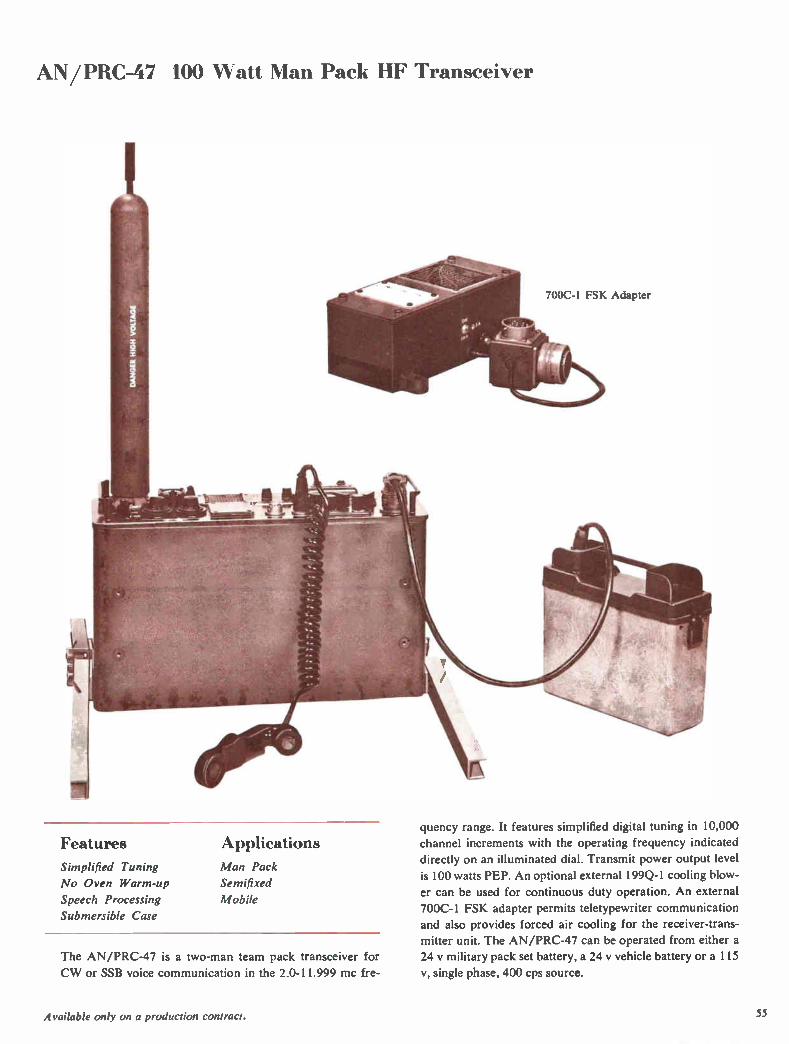
AN/PRC-47 100 Watt Man Pack HF Transceiver
Features Applications
Simplified Tuning Man Pack
No Oven Warm-up Semifixed
Speech Processing Mobile
Submersible Case
The AN/PRC-47 is a two-man team pack transceiver for
CW or SSB voice communication in the 2.0-11.999 mc fre-
700C- l FSK Adapter
quency range. It features simplified digital tuning in 10,000
channel increments with the operating frequency indicated
directly on an illuminated dial. Transmit power output level
is 100 watts PEP. An optional external 199Q-1 cooling blow-
er can be used for continuous duty operation. An external
700C-1 FSK adapter permits teletypewriter communication
and also provides forced air cooling for the receiver-trans-
mitter unit. The AN/PRC-47 can be operated from either a
24 y military pack set battery, a 24 y vehicle battery or a 115
v, single phase, 400 cps source.
Available only on a production contract. 55
AN/PRC-47 100 Watt Man Pack HF Transceiver
APPLICATION CONFIGURATIONS
The AN/PRC-47 can be used for forward echelon combat
control, guiding air supply or paratroop drops, long range
reconnaissance missions, front line administration or tacti-
cal networks. It can be mounted on a Jeep for rear echelon
or front line employment.
Two rucksack frames facilitate man pack use: one is used to
carry the transceiver; the other, the battery supply, antenna
and accessories. The AN/PRC-47 is also ideally suited to the
vibration environments of vehicular operation and can be in-
stalled quickly by the use of optional mounting clamps. Pow-
er can be obtained from the vehicle battery-generator system,
and it can use either the antenna supplied or a mobile whip.
The transceiver is operationally compatible with the AN/
MRC-83, AN/M RC-87, AN/MRC-94, AN/M RC-95, AN/
TRC-69, AN/TRC-75, AN/TRC-91, AN/TSC-15, AN/
TSC-38 and other similar single sideband equipment.
The AN/PRC-47 can be set up for operation by a two-man
team in a few minutes. In operation, a leg attaches to each of
the four corners of the case to give stability. Wire radials are
unwound and connected to the transceiver case to form a
ground plane for the antenna. A 15-foot sectional whip an-
tenna, which fastens directly to an insulator on the trans-
ceiver front panel, completes the installation. For storage
or vehicular transport, a watertight case accommodates the
entire system.
CIRCUITRY
The AN/PRC-47 uses a stabilized master oscillator with no
oven. This reduces power drain and requires no warm-up.
Balanced modulators and Mechanical Filters for sideband
separation in transmit give excellent carrier suppression and
negligible interchannel cross-talk.
Tuning and loading of the power amplifier are facilitated by
a visual power output indicator. An audio channel circuit
can be used for a sidetone signal. The AN/PRC-47 Trans-
ceiver uses a standard military H-33G/PT handset.
MODULAR CONSTRUCTION
Major circuits are arranged in six modules — RF oscillator,
signal data-translator, amplifier-modulator, oscillator con-
trol, audio amplifier and power supply. Mechanical connec-
tions, where required, permit easy module removal. Test
points for all significant circuit voltages are located on the
top of each module to facilitate rapid trouble isolation.
Specifications FREQUENCY RANGE: 2.0-11.999 mc.
FREQUENCY STABILITY:
NUMBER OF CHANNELS:
±25 cps.
10,000 1 kc channels.
MODES: USB — Voice, MCW or FSK.
IMPEDANCES: Receiver RF input 50 ohms. Transmitter out-
put network capable of matching a 15-foot whip antenna or
a 50 ohm resistive load. Receiver audio output 300 ohms.
EXTERNAL POWER SOURCE: 24 v dc or 115 v, 400 cps nominal.
Negative ground battery is interchangeable with the one used
in the AN/PRC-38 or AN/PRC-41 Radio Set.
INPUT POWER: Transmit, less than 320 watts; receive, less
than 18 watts.
SIZE:
Transceiver 23 1/4 " 58.74 cm
H
13 11/16" 34.77 cm
D
6 15/16" 17.62 cm
Battery case 4" 97/s" 11 9/16" 10.16 cm 25.08 cm 29.37 cm
WEIGHT: Transceiver — Approx. 41 lbs. (18.6 kg). Battery
and case — 17 lbs. (7.71 kg).
TRANSMITTING CHARACTERISTICS
POWER OUTPUT: Choice of 100 watt or 20 watt PEP levels.
AUDIO FIDELITY: ± 6 db from 300-3000 cps, relative to
1700 cps.
DISTORTION: Third order intermodulation products 30 db
down from either of two equal test tones at 100 watts PEP
using voice modulation.
CARRIER SUPPRESSION: 40 db down.
SPURIOUS OUTPUT: At least 50 db down from desired output.
RECEIVING CHARACTERISTICS
SENSITIVITY: 2 uy for 10 db signal-plus-noise-to-noise ratio;
50 mw minimum audio output.
SELECTIVITY: At —6 db — 300-3000 cps above channel fre-
quency (with response at 1700 cps above channel frequency
as reference). At —60 db — 1000 cps below channel fre-
quency to 4600 cps above channel frequency.
AVC CHARACTERISTICS: Less than 10 db audio output varia-
tion for input signals from 5-100,000 uy.
AUDIO OUTPUT: 500 milliwatts, 1000 uy input.
AUDIO DISTORTION: Less than 15%.
Related Equipment 700C-1 FSK Adapter, p. 123
56

AN/URC-32 HF Transceiver
Features Applications 28,000 Channels
Digital Tuning
Excellent Stability
Optional Shockmounts
Complete Accessibility
Shipboard Communication
Fixed Station
The AN/URC-32, a rack mounted single sideband trans-
ceiver, provides simplex operation in the 2-30 mc frequency
range with 500 watts PEP output. Continuous coverage is
provided in 1 kc increments with channel frequency indi-
cated directly on an illuminated counter-type dial. Frequen-
cy coverage in 0.1 kc steps is optionally available. A choice
of modes includes upper sideband, lower sideband, inde-
pendent sideband (separate channels on each sideband),
AM, RTTY or CW.
SYSTEM APPLICATIONS
The AN/URC-32 is well suited for shipboard, fixed or trans-
portable communication systems. Shockmounts which pro-
vide excellent isolation for shipboard installation are avail-
able for the equipment rack.
HIGH FREQUENCY STABILITY
On-frequency channel selection, without searching or fine
tuning, is assured by an integral transistorized frequency
standard with a stability of one part in 10' per month. An
external Collins 40N-1 Frequency Standard can be used in
installations requiring stabilities of one part in l0 r per day.
Manual tuning of the transmitter places the receive circuits
in proper adjustment when reception on the same frequency
is desired.
MAXIMUM ACCESSIBILITY
Circuitry is divided into logical groups on individual chassis
which feature quick disconnect devices. Each chassis is
mounted on the rack with swing-out type hinges providing
complete access to all components and wiring. Many of the
units have plug-in modules or subunits to further facilitate
inspection and maintenance.
MODERN CIRCUITRY
Receiver and exciter circuits employ double conversion
above 3.7 mc. Balanced modulators and Mechanical Filters
provide excellent carrier suppression and negligible inter-
channel cross-talk. The power amplifier is a two-stage, four-
band unit with excellent linearity. Included is a frequency
comparator that can be used to check the received signal
with an external standard if desired.
gmft..41/
,
71‘
BPI
_
4.1
Available only on a production contract. 57
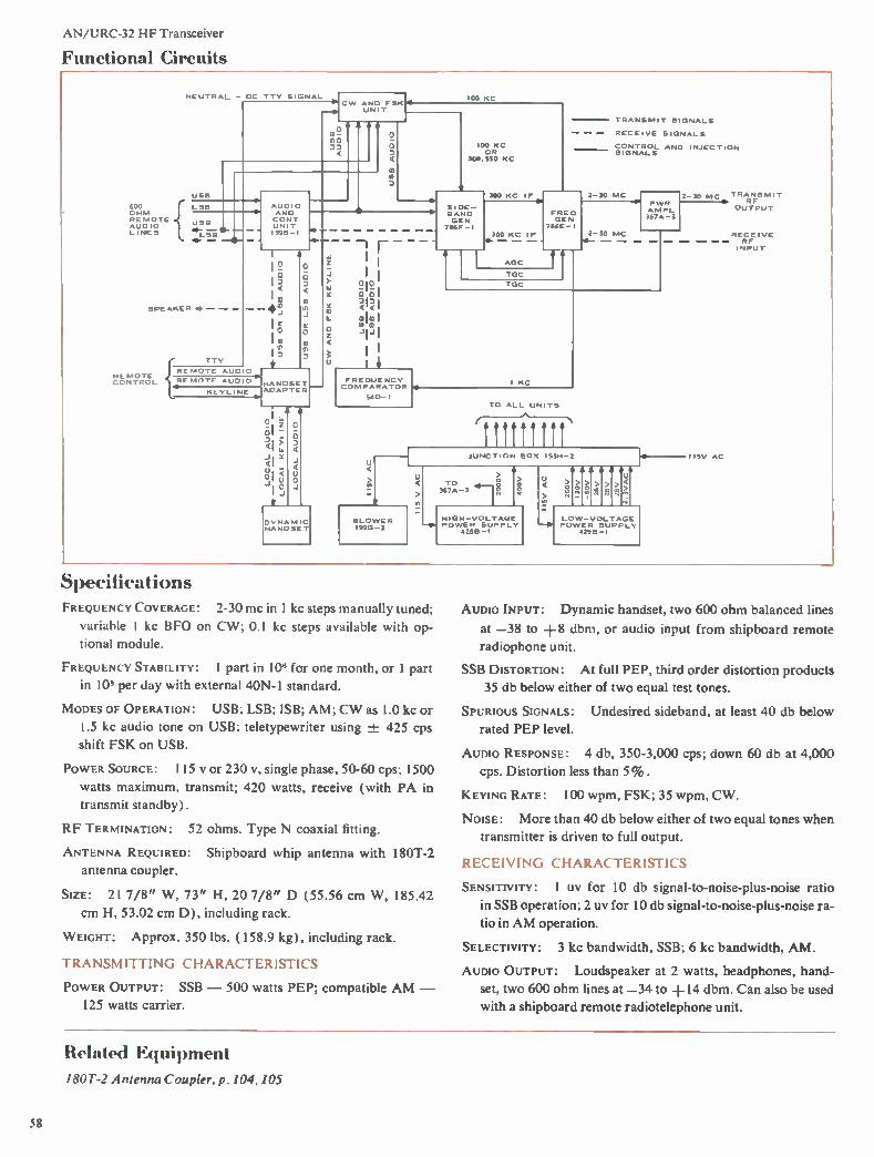
AN /URC-32 HF Transceiver
Functional Circuits
600 OHM REMOTE AUDIO L I NE S
NEUTRAL - DC TTY SIGNAL
USE!
CW AND FSK UN IT
LSB
USB —
L SS 911., —
SPEAKER «O.-.
{RE MOTE AUD nn?,,,Tc, HF MOTE AU
11
TTY
(2, O
KEYLINE
AUDIO AND CONT UNIT I59B- I
O
03 O
HANDSET ADAPTER
DYNAMIC HANDSET
0
o
0
D
o
10
100 KC
FREQUE NCY COMPARATOR
540-I
BLOWER I99G-3
4
100 KC OR
300.530 KC
*__
SIDE-1. SAND
GEN 786F-I
300 KC IF
300 KC IF 4.
AGC
FRED GEN
786E-1
TRANSMIT SIGNALS
RECEIVE SIGNALS
CONTROL AND INJECTION SIGNALS
2-30 MC
TGC
TGC
2-30 MC
PWR AM PL 367A-3
I KC
TO ALL UNI TS
JUNC TION BOX 153H-2
U 10 TO
367A-3 '471
HIGH-VOLTAGE POWER SUPPLY
42813-1
0 0 > > co .?e,
LOW-VOLTAGE .-18. POWER SUPPLY
42913 -1
2_ 30 m , TRANSMIT RF
OUTPUT
RECEIVE - RF
INPUT
I 15V AC
Specifications
FREQUENCY COVERAGE: 2-30 mc in 1 kc steps manually tuned;
variable I kc BFO on CW; 0.1 kc steps available with op-
tional module.
FREQUENCY STABILITY: 1 part in 106 for one month, or 1 part
in l 0 per day with external 40N-1 standard.
MODES OF OPERATION: USB; LSB; ISB; AM; CW as 1.0 kc or
1.5 kc audio tone on USB: teletypewriter using ± 425 cps
shift FSK on USB.
POWER SOURCE: 115 y or 230 v, single phase, 50-60 cps; 1500
watts maximum, transmit; 420 watts, receive (with PA in
transmit standby).
RF TERMINATION: 52 ohms. Type N coaxial fitting.
ANTENNA REQUIRED: Shipboard whip antenna with 180T-2
antenna coupler.
SIZE: 21 7/8" W, 73" H, 20 7/8" D (55.56 cm W, 185.42
cm H, 53.02 cm D), including rack.
W EIGHT: Approx. 350 lbs. (158.9 kg), including rack.
TRANSM ITTING CHARACTERISTICS
POWER OUTPUT: SSB — 500 watts PEP; compatible AM —
125 watts carrier.
AUDIO INPUT: Dynamic handset, two 600 ohm balanced lines
at —38 to +8 dbm, or audio input from shipboard remote
radiophone unit.
SSB DISTORTION: At full PEP, third order distortion products
35 db below either of two equal test tones.
SPURIOUS SIGNALS: Undesired sideband, at least 40 db below
rated PEP level.
AUDIO RESPONSE: 4 db, 350-3,000 cps; down 60 db at 4,000
cps. Distortion less than 5%.
KEYING RATE: 100 wpm, FSK; 35 wpm, CW.
NOISE: More than 40 db below either of two equal tones when
transmitter is driven to full output.
RECEIVING CHARACTERISTICS
SENSITIVITY: 1 uy for 10 db signal-to-noise-plus-noise ratio
in SSB operation; 2 uy for 10 db signal-to-noise-plus-noise ra-
tio in AM operation.
SELECTIVITY: 3 kc bandwidth, SSB; 6 kc bandwidth, AM.
AUDIO OUTPUT: Loudspeaker at 2 watts, headphones, hand-
set, two 600 ohm lines at —34 to +14 dbm. Can also be used
with a shipboard remote radiotelephone unit.
Related Equipment
180T-2 Antenna Coupler, p. 104, 105
58
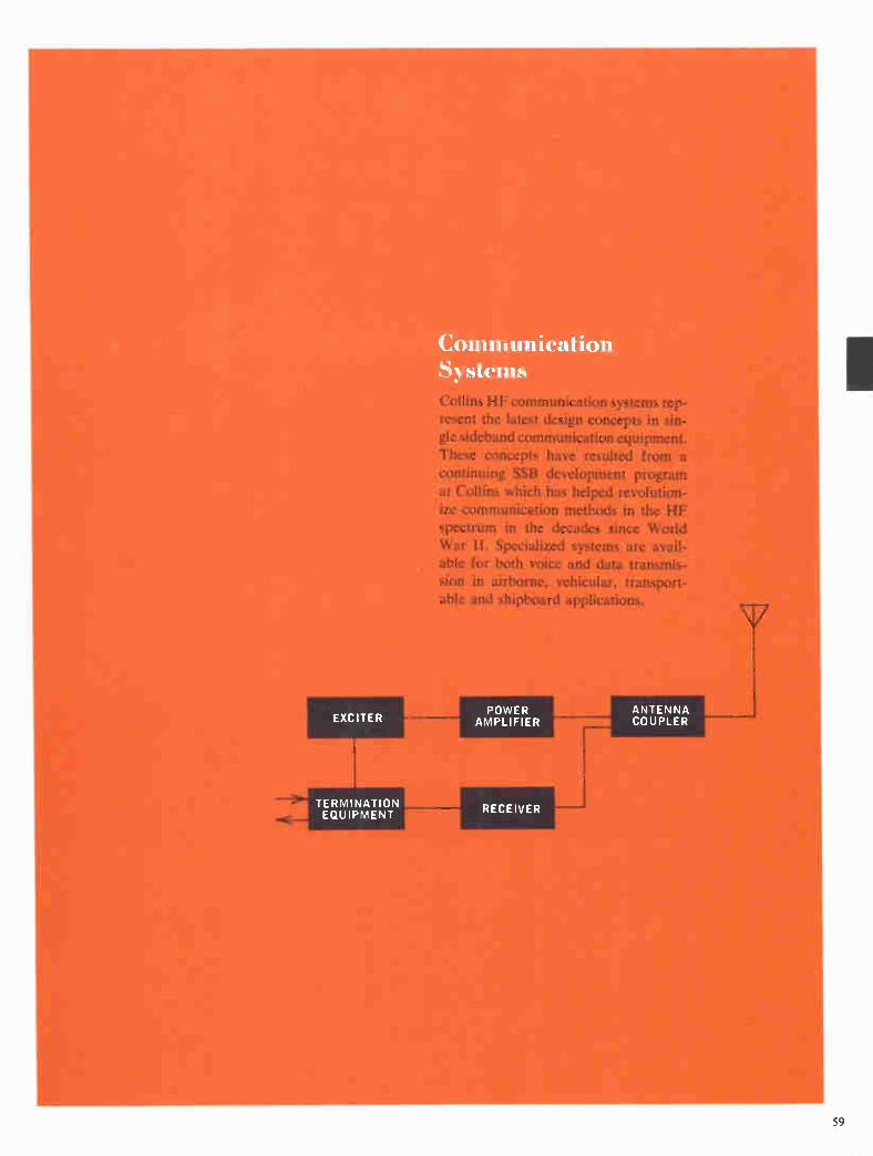
EXCITER
TERMINATION EQUIPMENT
Communication Systems Collins HF communication systems rep-resent the latest design concepts in sin-gle sideband communication equipment. These concepts have resulted from a continuing SSB development program
at Collins which has helped revolution-ize communication methods in the HF spectrum in the decades since World War II. Specialized systems are avail-able for both voice and data transmis-sion in airborne, vehicular, transport-able and shipboard applications.
POWER AMPLIFIER
RECEIVER
ANTENNA COUPLER
59

ANNA4 Air Transportable HF Communication System
REMOTE AREA OPERATION Features
High Mobility
Lightweight
Self-contained
One-Man Operation
Two Independent Systems
Applications
A ir Transportable
The ANNA-1 HF Communication System provides either
simplex or full duplex operation on two independent radio circuits, which are automatically tuned in 0.1 kc channel in-
crements throughout the 2.0-29.9999 mc frequency range.
Transmit power output is 1 kw PEP or average. Choice of
modes includes upper sideband, lower sideband, independent
sidebands or AM, together with voice frequency telegraph
facilities.
An RF patch panel permits a choice of antennas for either system. The selection includes a semidirectional, horizontal-
ly-polarized log-periodic for short to medium range, point-to-
point communication and a vertically-polarized, omnidirec-
tional monopole with low angle radiation for ship-to-shore
and ground-to-air communication. A 32 ft. whip can be in-
stalled on the shelter to provide an operational radio circuit
within minutes after the equipment is moved on site. Receiver
bandpass filters allow transmit-receive frequency separation as low as 10%.
Lightweight shelters used in the system can be easily trans-
ported by cargo aircraft, as well as railroad, ship or rubber-tired vehicles.
Each terminal contains all necessary equipment, including
antennas, primary power generator and maintenance facili-
ties, to quickly establish voice and teletypewriter communi-
cation for support of government or commercial operations
in remote geographical locations. Air conditioning and heat-
ing maintain shelter temperatures at reasonable levels for
efficient operation.
Separate operator consoles for radio and audio facility con-
trol functions are located directly behind the TTY machines
to enable one operator to have complete station control.
SYSTEM CONFIGURATION
The terminal is housed in three major subsystems — a com-
munication shelter, an electronic maintenance shelter and a
power generator. The communication shelter houses the op-
erator console and all facilities for two integral, full duplex,
HF SSB radio terminals including RTTY message capabili-
ties. The electronic maintenance shelter provides storage
space and work area for adjustment and repair of subsystems at remotely located sites.
The modified military type S-141A/G shelters have 3" pro-
tective skid rails, square inside corners, and are equipped with
60 Available only on a production contract.

roof access steps. Separate air conditioning and heating units
are included in each shelter. The system is capable of with-
standing low level shock and vibration encountered by rail-
road, cargo aircraft, ship and rubber-tired vehicles employed
in transport. A type III military transporter can be used for
transport over highways and unimproved terrain.
Power fop the terminal is supplied by a 30 kw diesel gener-
ator. Its output is 120 v or 208 v, 60 cps, 3 phase, 4-wire with
5% voltage and frequency regulation. A fuel tank with suf-
4
RADI 0 CONT
AUDIO CONT
OPR CSL—
AIR COND (HEAT AND COOL)
o 06
28 KSR e 9 TTY V CL <
1 1*V.' L
ANNA-1 Air Transportable HF Communication System
ficient capacity for eight hours of operation is supplied.
SIMPLIFIED MAINTENANCE
Modular electronic equipment, together with circuit card
techniques, is used where applicable to facilitate maintenance
and spare parts logistics. All interunit wiring terminates at a
distribution frame, providing flexibility in interconnection of
components and readily accessible test points.
PWR CONT ne-- AND DI STR
DOOR 41— END
MODEL 28 ASR TTY
Communication Shelter Left Wall Layout
Communication Shelter Floor Plan
Specifications
GENERAL
FREQUENCY RANGE: 2.0-29.9999 mc.
TUNING INCREMENTS: 0.1 kc steps.
FREQUENCY STABILITY: 1 part in 10 per day.
TUNING: Completely automatic.
CONTROL: Local operator.
POWER OUTPUT: 1 kw PEP or average.
MODE OF OPERATION: Duplex or simplex (patch selectable).
RECEIVE FREQUENCY SEPARATION: 10% from transmitter
frequency.
CHANNELIZATION: Two independent 3 kc channels.
TRANSMISSION MODES: USB and AM, normal operation. LSB
and ISB, simple patching.
AUDIO TERMINATIONS: O db level, 600 ohms.
CHANNELIZATION: Channel A — 1 db P/P ripple, +350 to
+3040 cps; —60 db points, —75 and +3300 cps. Channel
B — 1 db P/P ripple, —350 to —3040 cps; —60 db points,
+75 and —3300 cps.
TTY FACILITIES: Includes frequency shift keyers and con-
verters, dc loop control and TTY patching panel.
ANTENNAS: Type 437C-3A, vertically-polarized omnidirec-
tional. Type 637E-1, horizontally-polarized log-periodic, and
a 32 ft. whip antenna.
PRIMARY POWER: 208 v, 60 cps, 3 phase, wye connected. Peak
power requirement is approximately 22 kw. Diesel driven
generator normally furnished as part of system.
Size Weight H D
*Main- 81" 83" 142" 3895 lbs. tenance 205.74 cm 210.82 cm 360.68 cm 1766.77 kg shelter
*Commu- 81" 83" 142" 5295 lbs. nication 205.74 cm 210.82 cm 360.68 cm 2401.81 kg shelter
Diesel 60" 78" 96" 3925 lbs. generator 152.4 cm 198.12 cm 241.3 cm 1780.38 kg
437C-3A tower skid
*With antenna stowed.
54" 60" 126" 1670 lbs. 137.16 cm 152.4 cm 320.04 cm 757.51 kg
Basic Units 714Y -2 Frequency Control, p.90
789R-I IF Translator, p. 88-90
789T-1 IF Translator, p. 88-90
618Z-4 RF Translator, p. 87
635T-2 Receiver Bandpass Filter, p. 111, 112
548L-4 1 KW Power Amplifier, p. 37
180R-6/309A-2E Antenna Coupler and Control, p. 102, 103
61
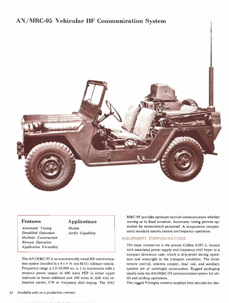
AN/NIRC-95 Vehicular HF Communication System
Features Applications
Automatic Tuning Mobile
Simplified Operation A irlift Capability
Modular Construction
Remote Operation
Application Versatility
The AN/MRC-95 is an automatically tuned HF communica-
tion system installed in a 4 x 4 1/4 -ton M151 military vehicle.
Frequency range is 2.0-29.999 mc in 1 kc increments with a
transmit power output of 400 watts PEP in either upper
sideband or lower sideband and 100 watts in AM with re-
inserted carrier, CW or frequency shift keying. The AN/
M RC-95 provides optimum tactical communication whether
moving or in fixed locations. Automatic tuning permits op-
eration by nontechnical personnel. A temperature compen-
sated standard assures instant on-frequency operation.
EQUIPMENT CONFIGURATIONS
The basic transceiver is the proven Collins 618T-3, housed
with associated power supply and frequency shift keyer in a
compact aluminum case, which is drip-proof during opera-
tion and watertight in the transport condition. The local-
remote control, antenna coupler, load coil, and auxiliary
speaker are of watertight construction. Rugged packaging
ideally suits the AN/M RC-95 communication system for air-
lift and airdrop operations.
The rugged Fiberglas antenna employs four sections for mo-
62 Available only on a production contract.
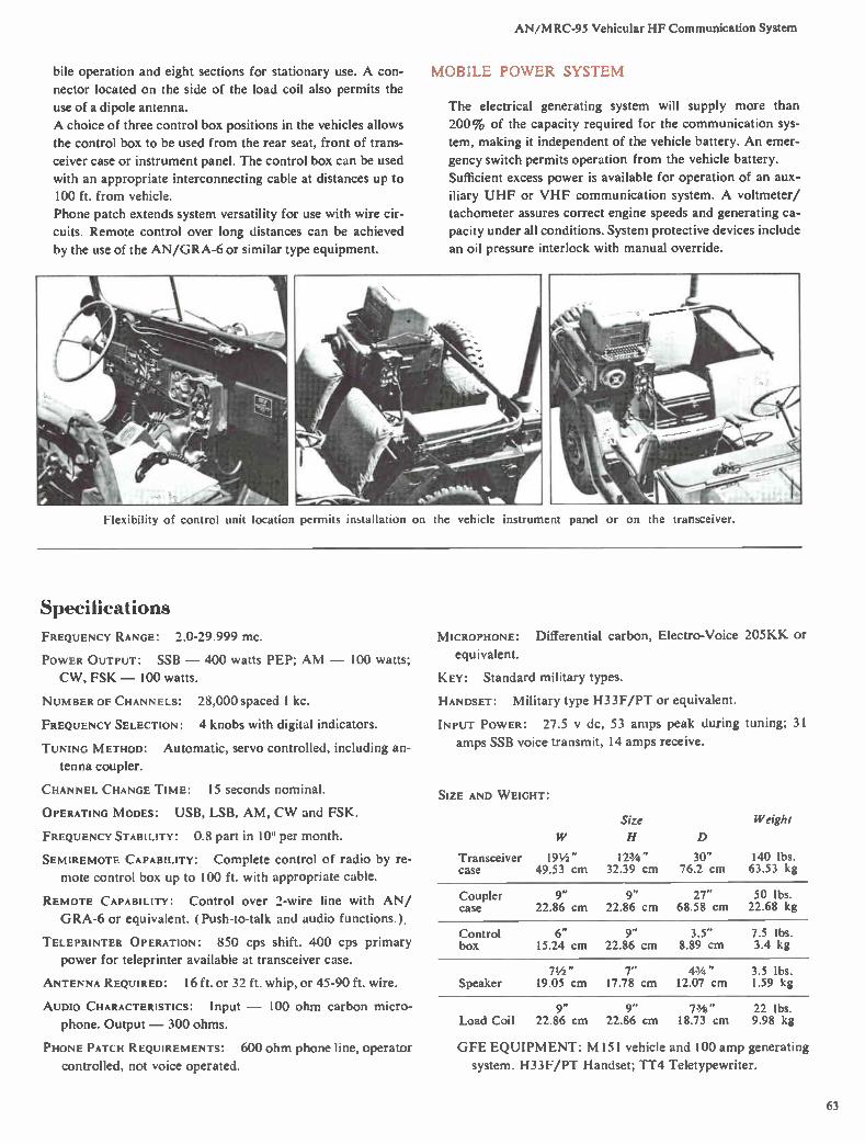
AN/MRC-95 Vehicular HF Communication System
bile operation and eight sections for stationary use. A con-
nector located on the side of the load coil also permits the
use of a dipole antenna.
A choice of three control box positions in the vehicles allows
the control box to be used from the rear seat, front of trans-
ceiver case or instrument panel. The control box can be used
with an appropriate interconnecting cable at distances up to
100 ft. from vehicle.
Phone patch extends system versatility for use with wire cir-
cuits. Remote control over long distances can be achieved
by the use of the AN/GRA-6 or similar type equipment.
MOBILE POWER SYSTEM
The electrical generating system will supply more than
200% of the capacity required for the communication sys-
tem, making it independent of the vehicle battery. An emer-
gency switch permits operation from the vehicle battery.
Sufficient excess power is available for operation of an aux-
iliary UHF or VHF communication system. A voltmeter/
tachometer assures correct engine speeds and generating ca-
pacity under all conditions. System protective devices include
an oil pressure interlock with manual override.
Flexibility of control unit location permits installation on the vehicle instrument panel or on the transceiver.
Specifications
FREQUENCY RANGE: 2.0-29.999 MC.
POWER OUTPUT: SSB — 400 watts PEP; AM — 100 watts;
CW, FSK — 100 watts.
NUMBER OF CHANNELS:
FREQUENCY SELECTION:
28,000 spaced 1 kc.
4 knobs with digital indicators.
TUNING METHOD: Automatic, servo controlled, including an-
tenna coupler.
CHANNEL CHANGE TIME: 15 seconds nominal.
OPERATING MODES: USB, LSB, AM, CW and FSK.
FREQUENCY STABILITY: 0.8 part in 10'. per month.
SEMIREMOTE CAPABILITY: Complete control of radio by re-
mote control box up to 100 ft. with appropriate cable.
REMOTE CAPABILITY: Control over 2-wire line with AN/
GRA-6 or equivalent. ( Push-to-talk and audio functions.).
TELEPRINTER OPERATION: 850 cps shift. 400 cps primary
power for teleprinter available at transceiver case.
ANTENNA REQUIRED: 16 ft. or 32 ft. whip, or 45-90 ft. wire.
AUDIO CHARACTERISTICS: Input — 100 ohm carbon micro-
phone. Output — 300 ohms.
PHONE PATCH REQUIREMENTS: 600 ohm phone line, operator
controlled, not voice operated.
MICROPHONE: Differential carbon, Electro-Voice 205KK or
equivalent.
KEY: Standard military types.
HANDSET: Military type H33F/PT or equivalent.
INPUT POWER: 27.5 y dc, 53 amps peak during tuning; 31
amps SSB voice transmit, 14 amps receive.
SIZE AND WEIGHT:
Transceiver case
Size Weight
W H D
19 1/2 " IVA " 30" 140 lbs. 49.53 cm 32.39 cm 76.2 cm 63.53 kg
Coupler case
9" 9" 27" 50 lbs. 22.86 cm 22.86 cm 68.58 cm 22.68 kg
Control box
6" 9" 3.5" 7.5 lbs. 15.24 cm 22.86 cm 8.89 cm 3.4 kg
71/2 " 7" 43/4 " 3.5 lbs. Speaker 19.05 cm 17.78 cm 12.07 cm 1.59 kg
9" 9" 73/4 " 22 lbs. Load Coil 22.86 cm 22.86 cm 18.73 cm 9.98 kg
GFE EQUIPMENT: M151 vehicle and 100 amp generating
system. H 33F/PT Handset; TT4 Teletypewriter.
63

AN/SRC-16 Shipboard HF Communication S->stem
d•re«111 t---T 0,40:0 • . — - --
• ,•1 I ----.. :....— :_ ; -.-....?....z...::-.:: I I; a. • • '
17. 0
ili«,U
1
a •*,
Features Applications Automatic Tuning Shipboard
Simultaneous Channels Fixed Station
Mode Choice
Data Transmission
Simplified Maintenance
The AN/SRC-16 is a high capacity, long range HF commu-
nication system which provides four independent transmit
and four independent receive channels. The system includes
two 5 kw linear amplifiers which can be switched into any
two transmit channels in lieu of the 500 watt amplifiers nor-
mally used.
Frequency coverage is in 1 kc tuning increments over the
2.0-29.999 mc range. Operating mode choice includes AM,
CW, MCW, FSK, SSB. ISB and data communication on each
channel. The channel frequency of each transmitter and re-
ceiver is phase locked to a primary frequency standard assur-
ing high signal stability.
CIRCUIT FEATURES
Linear power amplifiers, high performance filters and low
distortion circuitry meet all complex data transmission and
reception performance requirements. Compatible AM is
transmitted using the upper sideband and a reinserted carrier.
Pi network output circuitry assures efficient antenna load-
ing. The converter for FSK-CW mode reception includes an
oscilloscope to monitor test tones and to facilitate BFO ad-
justment on FSK reception.
RF LEVEL CONTROL
A variable attenuator, using transistor circuitry, provides au-
tomatic control of radiated or received power levels. The RF
signal between the transmitter and RF amplifier can be at-
tenuated up to 120 db. Normally, it is automatically con-
trolled by direct current pulses. It can be switched to the re-
ceiver input to manually attenuate the RF signal level.
ANTENNA SWITCHING
The AN/SRC-16 employs 12 automatic antenna couplers
. • '
I
¡aim Eau um ill1111111
with terminations for three or more antennas. In a typical in-
stallation, eight couplers are associated with the 2-6 mc an-
tenna, two couplers with the 5-15 mc antenna and two with
the 10-30 mc antenna. Other arrangements are optionally
available to meet individual system requirements. An RF
switching matrix located in the HF coupler cabinet connects
individual channel equipment to the proper antenna couplers.
The couplers permit duplex operation on all channels by iso-
lating transmit and receive circuitry, as well as maintaining
the correct antenna impedance match. External equipments,
such as the AN/URC-32, AN/WRT-2, AN/SRT- 14 and
AN/SRT- 15, can also be connected to the antenna matrix
through auxiliary input jacks.
INPUT PATCHING
A communication patching switchboard permits connecting
remote input audio lines to any of the radio channels. Inter-
locked pushbutton selectors prevent improper operation, and
visual or aural signals indicate equipment status. Voice com-
pression and noise squelching facilitate voice communica-
tions. Redundant power supplies prevent central control
failure in the event of a single power supply malfunction.
SYSTEM TEST FACILITIES
An integral multipurpose test set simplifies system mainte-
nance tests. A two-tone signal can be applied to either trans-
mitted sideband for distortion measurements and check of
performance quality. A sidetone containing the signal is sam-
pled at the T/R relay, coupled to the receiver input, demodu-
lated and passed to a distortion measuring circuit which an-
alyzes the hum level at 400 cps and 800 cps, third order dis-
tortion products and the second harmonic of the F I tone.
Frequency lock is tested by transmitting one of two tones on
both LSB and USB in a closed loop throughout the system.
UNITIZED CONSTRUCTION
The entire system is housed in eight separate equipment cab-
inets. Maintenance and installation are simplified through the
use of modular construction. Individual units are mounted
on slide cabinet drawers and all electrical connections are
made through mating connectors wherever possible. Addi-
64 Available only on a production contract.
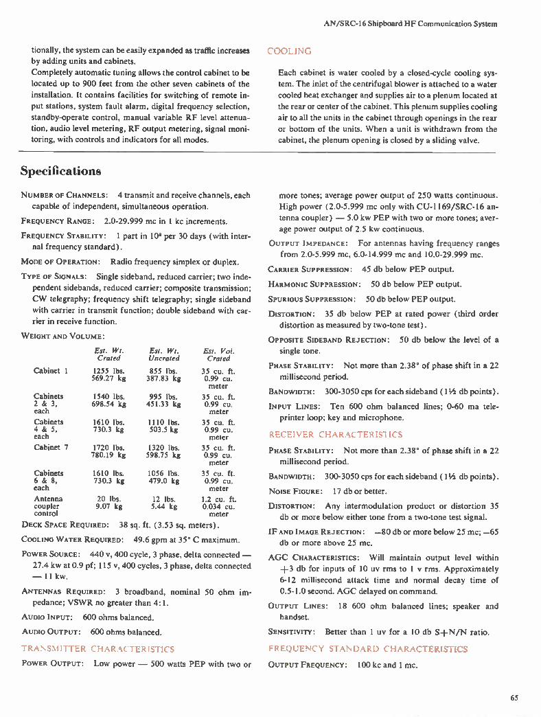
AN/SRC-I6 Shipboard HF Communication System
tionally, the system can be easily expanded as traffic increases
by adding units and cabinets.
Completely automatic tuning allows the control cabinet to be
located up to 900 feet from the other seven cabinets of the
installation. It contains facilities for switching of remote in-
put stations, system fault alarm, digital frequency selection,
standby-operate control, manual variable RF level attenua-
tion, audio level metering, RF output metering, signal moni-
toring, with controls and indicators for all modes.
COOLING
Each cabinet is water cooled by a closed-cycle cooling sys-
tem. The inlet of the centrifugal blower is attached to a water
cooled heat exchanger and supplies air to a plenum located at
the rear or center of the cabinet. This plenum supplies cooling
air to all the units in the cabinet through openings in the rear
or bottom of the units. When a unit is withdrawn from the
cabinet, the plenum opening is closed by a sliding valve.
Specifications
NUMBER OF CHANNELS: 4 transmit and receive channels, each
capable of independent, simultaneous operation.
FREQUENCY RANGE: 2.0-29.999 mc in 1 kc increments.
FREQUENCY STABILITY: 1 part in 108 per 30 days (with inter-
nal frequency standard).
MODE OF OPERATION: Radio frequency simplex or duplex.
TYPE OF SIGNALS: Single sideband, reduced carrier; two inde-
pendent sidebands, reduced carrier; composite transmission;
CW telegraphy; frequency shift telegraphy; single sideband
with carrier in transmit function; double sideband with car-
rier in receive function.
WEIGHT AND VOLUME:
Cabinet 1
Cabinets 2 & 3, each
Cabinets 4 & 5, each
Cabinet 7
Est. Wt. Crated
1255 lbs. 569.27 kg
1540 lbs. 698.54 kg
Est. Wt. Uncrated
855 lbs. 387.83 kg
995 lbs. 451.33 kg
1610 lbs. 1110 lbs. 730.3 kg 503.5 kg
1720 lbs. 780.19 kg
1320 lbs. 598.75 kg
Cabinets 1610 lbs. 1056 lbs. 6 & 8, 730.3 kg 479.0 kg each
Antenna 20 lbs. 12 lbs. coupler 9.07 kg 5.44 kg control
Est. Vol. Crated
35 Cu. ft. 0.99 Cu. meter
35 Cu. ft. 0.99 Cu. meter
35 Cu. ft. 0.99 Cu. meter
35 Cu. ft. 0.99 Cu. meter
35 Cu. ft. 0.99 Cu. meter
1.2 Cu. ft. 0.034 Cu. meter
DECK SPACE REQUIRED: 38 sq. ft. (3.53 sq. meters).
COOLING WATER REQUIRED: 49.6 gpm at 35° C maximum.
POWER SOURCE: 440 v, 400 cycle, 3 phase, delta connected —
27.4 kw at 0.9 pf; 115 v, 400 cycles, 3 phase, delta connected
— 11 kw.
ANTENNAS REQUIRED: 3 broadband, nominal 50 ohm im-
pedance; VSWR no greater than 4:1.
AUDIO INPUT: 600 ohms balanced.
AUDIO OUTPUT: 600 ohms balanced.
TRANSMITTER CHARACTERISTICS
POWER OUTPUT: Low power — 500 watts PEP with two or
more tones; average power output of 250 watts continuous.
High power (2.0-5.999 mc only with CU-1169/SRC-16 an-
tenna coupler) — 5.0 kw PEP with two or more tones; aver-
age power output of 2.5 kw continuous.
OUTPUT IMPEDANCE: For antennas having frequency ranges
from 2.0-5.999 mc, 6.0-14.999 mc and 10.0-29.999 mc.
CARRIER SUPPRESSION: 45 db below PEP output.
HARMONIC SUPPRESSION: 50 db below PEP output.
SPURIOUS SUPPRESSION: 50 db below PEP output.
DISTORTION: 35 db below PEP at rated power (third order
distortion as measured by two-tone test).
OPPOSITE SIDEBAND REJECTION: 50 db below the level of a
single tone.
PHASE STABILITY: Not more than 2.38° of phase shift in a 22
millisecond period.
BANDWIDTH: 300-3050 cps for each sideband (1 1/2 db points).
INPUT LINES: Ten 600 ohm balanced lines; 0-60 ma tele-
printer loop; key and microphone.
RECEIVER CHARACTER IS1 ICS
PHASE STABILITY: Not more than 2.38° of phase shift in a 22
millisecond period.
BANDWIDTH: 300-3050 cps for each sideband (1 1/2 db points).
NOISE FIGURE: 17 db or better.
DISTORTION: Any intermodulation product or distortion 35
db or more below either tone from a two-tone test signal.
IF AND IMAGE REJECTION: —80 db or more below 25 mc; —65
db or more above 25 mc.
AGC CHARACTERISTICS: Will maintain output level within
+3 db for inputs of 10 uy rms to 1 y rms. Approximately
6-12 millisecond attack time and normal decay time of
0.5-1.0 second. AGC delayed on command.
OUTPUT LINES: 18 600 ohm balanced lines; speaker and
handset.
SENSITIVITY: Better than 1 uy for a 10 db S+N/N ratio.
FREQUENCY STANDARD CHARACTERISTICS
OUTPUT FREQUENCY: 100 kc and 1 mc.
65
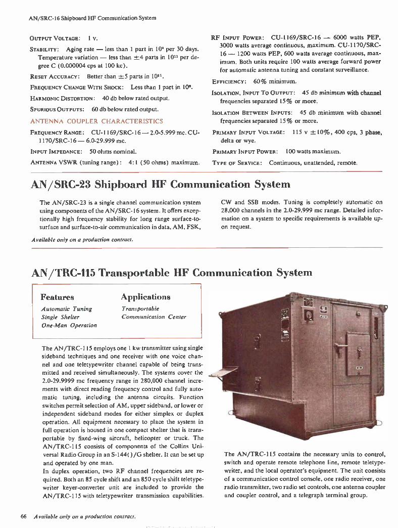
AN/SRC-16 Shipboard HF Communication System
OUTPUT VOLTAGE: 1 V.
STABILITY: Aging rate — less than 1 part in 108 per 30 days.
Temperature variation — less than -±-4 parts in 10" per de-
gree C (0.000004 cps at 100 kc).
RESET ACCURACY: Better than ±5 parts in 10".
FREQUENCY CHANGE W ITH SHOCK: Less than 1 part in 108.
HARMONIC DISTORTION: 40 db below rated output.
SPURIOUS OUTPUTS: 60 db below rated output.
ANTENNA COUPLER CHARACTERISTICS
FREQUENCY RANGE: CU-1169/SRC-16 — 2.0-5.999 mc. CU-
1170/SRC-16 — 6.0-29.999 mc.
INPUT IMPEDANCE: 50 ohms nominal.
ANTENNA VSWR (tuning range) : 4:1 (50 ohms) maximum.
RF INPUT POWER: CU-1169/SRC-16 — 6000 watts PEP,
3000 watts average continuous, maximum. CU-1170/SRC-
16 — 1200 watts PEP, 600 watts average continuous, max-
imum. Both units require 100 watts average forward power
for automatic antenna tuning and constant surveillance.
EFFICIENCY: 60% minimum.
ISOLATION, INPUT To OUTPUT: 45 db minimum with channel
frequencies separated 15% or more.
ISOLATION BETWEEN INPUTS: 45 db minimum with channel
frequencies separated 15% or more.
PRIMARY INPUT VOLTAGE: 115 v -± 10% , 400 cps, 3 phase,
delta or wye.
PRIMARY INPUT POWER: 100 watts maximum.
TYPE OF SERVICE: Continuous, unattended, remote.
AN/SRC-23 Shipboard 11F Communication System
The AN/SRC-23 is a single channel communication system
using components of the AN/SRC-16 system. It offers excep-
tionally high frequency stability for long range surface-to-
surface and surface-to-air communication in data, AM, FSK,
Available only on a production contract.
CW and SSB modes. Tuning is completely automatic on
28,000 channels in the 2.0-29.999 mc range. Detailed infor-
mation on a system to specific requirements is available up-
on request.
AN/TRC-115 Transportable HF Communication System
Features Applications
Automatic Tuning Transportable
Single Shelter Communication Center
One-Man Operation
The AN/TRC-115 employs one 1 kw transmitter using single
sideband techniques and one receiver with one voice chan-
nel and one teletypewriter channel capable of being trans-
mitted and received simultaneously. The systems cover the
2.0-29.9999 mc frequency range in 280,000 channel incre-
ments with direct reading frequency control and fully auto-
matic tuning. including the antenna circuits. Function
switches permit selection of AM, upper sideband, or lower or
independent sideband modes for either simplex or duplex
operation. All equipment necessary to place the system in
full operation is housed in one compact shelter that is trans-
portable by fixed-wing aircraft, helicopter or truck. The
AN/TRC-115 consists of components of the Collins Uni-
versal Radio Group in an S-144( )/G shelter. It can be set up
and operated by one man.
In duplex operation, two RF channel frequencies are re-
quired. Both an 85 cycle shift and an 850 cycle shift teletype-
writer keyer-converter unit are included to provide the
AN/TRC-115 with teletypewriter transmission capabilities.
The AN/TRC-115 contains the necessary units to control,
switch and operate remote telephone line, remote teletype-
writer, and the local operator's equipment. The unit consists
of a communication control console, one radio receiver, one
radio transmitter, two radio set controls, one antenna coupler
and coupler control, and a telegraph terminal group.
66 Available only on a production contract.

AN/TRC-115 Transportable HF Communication System
Functional Circuits
V 32I WHIP
RECE I VE ANT.
RADIO SET CONT AN/GRA-6
p
TO REMOTE TEL ORS
TO REMOTE TTY OPR
DATA SELECT
MODULES
1 0— — — —4- — — —
è ' MODE CONT
MODULE
714Y-2 FRED CONT
METER STATUS MODULE
I t
I 7I4Y-2 I
I CONTFRED I
I I
.- ---4- ---4 è
76914-1 I 616E-4 IF I RF
TRANS- TRANS-LATOR I LATOR
TO SYSTEM
426U-2 POWER SUPPLY
TO SYSTEM
I 426T- I
400 CPS I NV
r 635V-I
(en 4---L J
L.
•
CU -749 AUTO CPLR
3011A-2E COUPLER CONTROL
COAX FED ANT.
LOAD COIL
32. wHIP ANT.
Specifications
SHELTER: S-1440 /G.
TRANSMITTER POWER: 1 kw PEP or average.
FREQUENCY RANGE: 2.0-29.9999 mc in 0.1 kc steps.
MODES OF OPERATION: USB (3 kc), LSB (3 kc), ISB (each
sideband 3 kc), and compatible AM.
INFORMATION TYPES: Voice and/or voice frequency TTY.
MODE OF OPERATION: Full or half duplex.
CARRIER SUPPRESSION: Normal SSB operation is for carrier to
be fully suppressed (-50 db); optional reduced carrier op-
eration with three levels of suppression.
AFC: Optional.
IMAGE REJECTION: Below 20 mc, at least 80 db; above 20 mc,
at least 60 db.
FREQUENCY STABILITY: One part in 108 per day.
RMS STABILITY FACTOR: Does not exceed one part in 108 in
any 10-minute period.
RADIO EQUIPMENT
DESK
I DF
SIGNAL ENTRY BOX
CHAIR
AN/TRC-115 Floor Plan
TRANSMITTER DISTORTION PRODUCTS: Third and higher order
distortion suppressed at least 40 db; harmonic emission sup-
pressed at least 35 db, referenced with PEP level.
ANTENNAS: Transmit — 32 ft. whip, shelter mounted. Duplex
Receive — 32 ft. whip, field mounted. A dipole or any 50
ohm impedance antenna can also be used.
Basic Units 789R-1 IF Translator, p. 88-90
789T-I IF Translator, p. 88-90
618Z-4 RF Translator, p. 87
548L-4 1 KW Power Amplifier, p. 3'
635V-1 Bandpass Filter, p. 112
714Y -2 Frequency Control, p.90
700B-2 Teletypewriter Converter, p. 122, 123
426U-2 Power Supply, p. 86
67
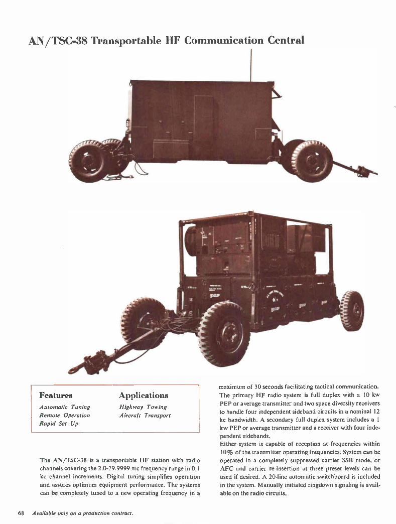
AN/TSC-38 Transportable IIF Communication Central
Features Automatic Tuning
Remote Operation
Rapid Set Up
Applications Highway Towing
Aircraft Transport
The AN/TSC-38 is a transportable HF station with radio
channels covering the 2.0-29.9999 mc frequency range in 0.1
kc channel increments. Digital tuning simplifies operation
and assures optimum equipment performance. The systems
can be completely tuned to a new operating frequency in a
maximum of 30 seconds facilitating tactical communication.
The primary HF radio system is full duplex with a 10 kw
PEP or average transmitter and two space diversity receivers
to handle four independent sideband circuits in a nominal 12
kc bandwidth. A secondary full duplex system includes a I
kw PEP or average transmitter and a receiver with four inde-
pendent sidebands.
Either system is capable of reception at frequencies within
10% of the transmitter operating frequencies. System can be
operated in a completely suppressed carrier SSB mode, or
AFC and carrier re-insertion at three preset levels can be
used if desired. A 20-line automatic switchboard is included
in the system. Manually initiated ringdown signaling is avail-
able on the radio circuits.
68 Available only on a production contract.

AN/TSC-38 Transportable HF Communication Central
MINIMUM SET UP TIME
The self-contained HF facility is housed in two mobile units
which can be transported by single C-130B, C-133, C-124,
or two C-119 aircraft; or towed by a prime mover over high-
ways, unimproved roads or cross country terrain. The equip-
ment is operational only minutes after arrival on site.
The AN/TSC-38 operates from either a 120 v or 208 v, 50-60
cps or 400 cps, 3 phase, wye connected power source with no
manual switching. The equipment will tolerate line voltage
and frequency with up to ± 10% variation.
Power for the complete system is provided by a primary and
a backup 65 kw, 400 cps turbine generator set. Batteries fur-
nish power for immediate touch-down and emergency opera-
tion of the secondary radio system and its associated terminal
equipment.
REMOTE OPERATION
The following radio system functions can be controlled from
a remote location — primary power control, sideband selec-
tion, frequency changing, ten preset conditions, operational
mode and push-to-talk operation, carrier reinsertion and
AFC selection.
EQUIPMENT CONFIGURATION
The system is a completely transportable configuration con-
sisting of two mobile units: an air conditioned S-141 shelter
and undercarriage which houses all electronic equipment;
and an undercarriage and pallet with installed primary power
engine generator and compartments for transportation of antennas, outside plant equipment and spare parts.
Functional Circuits
10 KW Power Amplifier All equipment easily accessible
UNIS •••-• TVZ:E PT
IS REMOTE TTY
SU IISCRI USERS
I RE MOTE I CRYPTO
SUBSCRIBER
• WIRE 20 LINE AUTOMATIC
SWITCHBOARD
SIGNAL MOD
RADIO fLL .---"CONTRO
RADIO INTERCEPT CHANNEL
OPT AUDIO ^ND CONTROL
CONTROLS
OATA/RC,,R SELECT
ANTENNAS
H 10 NW 1_1 H RC 12
RC‘ P NO
CONTROL —
DATA SELECT
RCyR
COMMON REMOTE CONTROL
69

AN/TSC-38 Transportable HF Communication Central
Specifications
FREQUENCY RANGE: 2.0-29.9999 mc.
TUNING INCREMENTS: 0.1 kc steps.
FREQUENCY STABILITY: 1 part in 108 per day.
TUNING: Completely automatic.
CONTROL: Local switch select, FSK dial-pulse select, and re-
mote FSK dial-pulse select over a 2- or 4-wire telephone line.
EXTERNAL SUBSCRIBERS: Twelve 2- or 4-wire (switch select-
able)
(1) 2- or 4-wire FSK dial, FSK push-to-talk (3 maximum).
(2) 2- or 4-wire dc dial common battery; maximum loop re-
sistance, 500 ohms (12 maximum).
2- or 4-wire common battery manual; maximum loop
resistance, 500 ohms ( 12 maximum).
(4) 2- or 4-wire local battery ringdown subscribers (6 maxi-
mum).
(5) 2- or 4-wire switchboard trunks (12 maximum).
TELEPHONE SWITCHING: Switchboard; 4-wire, dc dial, 20-
line, 10-link, single-register 28 y de loop operation. Attend-
ant; single DSA ( Dial Service Assistance) position.
VOICE FREQUENCY TELEGRAPHY GROUP
(PRIMARY)
(3)
CHANNELS: Sixteen 4-wire, full duplex circuits.
CHANNEL FREQUENCY: 425-2975 cps.
FREQUENCY SHIFT: -±-42.5 cps.
MODE OF OPERATION: Normal space diversity, switch-select-
able to 8-channel space/frequency diversity on an individual
channel basis.
VOICE FREQUENCY TELEGRAPHY GROUP
(SECONDARY)
CHANNELS: Two 4-wire circuits.
CHANNEL FREQUENCY: Any two between 425 and 2975 cps.
FREQUENCY SHIFT: -±-42.5 cps.
MODE OF OPERATION: Normal nondiversity, switch-selectable
to 1-channel frequency diversity.
VOICE FREQUENCY TELEGRAPHY GROUP
(WIDEBAND)
CHANNEL: One 4-wire full duplex nondiversity.
CHANNEL FREQUENCY: 2000 cps channel center frequency
425 cps shift.
CRYPTOGRAPHY
Space and cabling are provided for two full duplex on-line
terminals.
LOCAL TELETYPEWRITER
Two page-printer/keyboards; one typing reperforator, one
transmitter distributor equipment, and one combination re-
perforator/keyboard/transmit distributor.
EXTERNAL SUBSCRIBERS
Twenty 4-wire lines; 20 or 60 ma neutral or 30 ma polar.
PRIMARY RADIO-FULL DUPLEX
TRANSMITTER POWER OUTPUT: 10 kw PEP/average.
RECEIVERS: TWO (space diversity).
MODE OF OPERATION: Switch selection; full duplex or simplex.
FREQUENCY SEPARATION: 10% from transmitted frequency.
CHANNELIZATION: Four independent 3 kc channels in a 12 kc
assignment.
ANTENNA REQUIREMENTS: 1 each 10 kw transmit antenna
displaying 50 ohms with a VSWR of less than 3:1 from 2.5-
30.0 mc and 2:1 from 2.0-2.5 mc. 2 each, receive antennas
for space diversity reception.
SECONDARY RADIO-FULL DUPLEX
TRANSMIT POWER OUTPUT: 1 kw PEP/average.
CHANNELIZATION: One receiver with four 3 kc ISB channels.
MODE OF OPERATION: Switch selection; full duplex or simplex.
ANTENNA REQUIREMENTS: 1 transmit and 1 receive antenna
displaying 50 ohms with 3:1 VSWR or 32 ft. whip.
ANTENNAS SUPPLIED: Two 32 ft. whip antennas (within
shelter). Two receive sloping vee antennas (1 kw). One 10
kw transmit sloping vee antenna.
Basic Units Power Amplifiers, p. 34-37
789R-I IF Translator, p. 88-90
789T-I IF Translator, p. 88-90
618Z-4 RF Translator, p. 87
635V-I Harmonic Filter, p. 112
426U-2 Power Supply, p. 86
70
HF-105, -106, -107, -108, -109 HF Shipboard Systems
Features
Transceiver Case
Automatic Tuning
Command-Center Operation
Optional Power Sources
Easy Installation
Simplified Maintenance
Applications
Sinai! Boat
Landing Craft
Shipboard
The Collins HF-105, HF-106, HF-107, HF-108 and HF-109
are multiple purpose, single sideband radio systems which op-
erate from different primary power sources to meet a vari-
ety of application requirements.
The systems are automatically tuned and cover the 2.0-
29.999 mc frequency range in 28,000 channel increments.
Transmit power output is 400 watts in either upper or lower
sideband and 100 watts in AM with reinserted carrier, CW
or optional FSK.
The systems offer optimum tactical communication range
for small boats, landing craft and ships.
COMMAND-CENTER OPERATION
The ship's commanding officer is offered a new concept in
rapid communication, since the desired channel frequency
can be selected directly from a control unit in the command
center in much the same manner as an aircraft radio is oper-
ated. Tuning is completely automatic. Channel change time
is less than 30 seconds nominal. Complete operation of the
equipment requires no technical background.
Command Center Control Group
RAPID INSTALLATION
The systems can be quickly installed by ship's personnel
using only common skills, such as welding and cable wiring.
A routine installation requires only about 16 hours.
Equipment packaging in four basic units — transceiver,
command control group, antenna coupler group and power
supply group — makes installation adaptable to various
types of ships. The five HF communication systems are iden-
tical except for primary input power requirements.
The basic transceiver is the proven 618T housed in a type 1,
drip-proof, wrap-around case. Capability of remotely lo-
cated control unit and antenna coupler facilitates optimum
installation.
The watertight control group may be located up to 350 ft.
from the transceiver. In addition to all operating controls, it
includes an RF wattmeter to monitor over-all functioning of
the system during operation.
Flexibility in antenna location is made possible by a separate
antenna coupler which can be located up to 100 ft. from the
transceiver case.
EASE OF MAINTENANCE
The location of an equipment malfunction can be quickly
isolated by ship's personnel using a simplified procedure
which is outlined on a permanently attached plate located
near the control unit. Corrective maintenance is initiated by
substitution of one of the three easily replaced major system
units. This feature makes it especially suitable for small ships
which have limited space and equipment for trouble shooting.
71
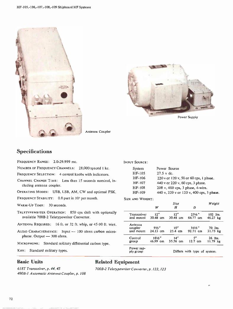
HF-105,-106,-107,-108,-109 Shipboard HF Systems
Specifications
14-
a.
Antenna Coupler
FREQUENCY RANGE: 2.0-29.999 mc.
NUMBER OF FREQUENCY CHANNELS: 28,000 spaced 1 kC.
FREQUENCY SELECTION: 4 control knobs with indicators.
CHANNEL CHANGE TIME: Less than 15 seconds nominal, in-
cluding antenna coupler.
OPERATING MODES: USB, LSB, AM, CW and optional FSK.
FREQUENCY STABILITY: 0.8 part in 10'; per month.
WARM-UP TIME: 30 seconds.
TELETYPEWRITER OPERATION: 850 cps shift with optionally
available 700B-2 Teletypewriter Converter.
ANTENNA REQUIRED: 16 ft. or 32 ft. whip, or 45-90 ft. wire.
AUDIO CHARACTERISTICS: Input — 100 ohms carbon micro-
phone. Output — 300 ohms.
MICROPHONE: Standard military differential carbon type.
KEY: Standard military types.
Power Supply
INPUT SOURCE:
System Power Source
HF-105 27.5 y dc.
HF-106 220 v or 120 v, 50 or 60 cps, 1 phase.
HF-107 440 y or 220 v, 60 cps, 3 phase.
HF- 108 208 v, 400 cps, 3 phase, 4-wire.
HF-109 440 v, 220 v or 120 v, 400 cps, 3 phase.
SIZE AND WEIGHT:
Size H D
Weight
Transceiver 12" 12" 25 1/2 " 102 lbs. and mount 30.48 cm 30.48 cm 64.77 cm 46.27 kg
Antenna coupler 91/2 " 10" and mount 24.13 cm 25.4 cm
361/2 " 70 lbs. 92.71 cm 31.75 kg
Control group
181/2 " 14" 5" 26 lbs. 46.99 cm 35.56 cm 12.7 cm 11.79 kg
Power sup-ply group Differs with type of system.
Basic Units Related Equipment
618T Transceiver, p. 44, 45 700B-2 Teletypewriter Converter, p. 122, 123
490B-1 Automatic Antenna Coupler, p. 108
72
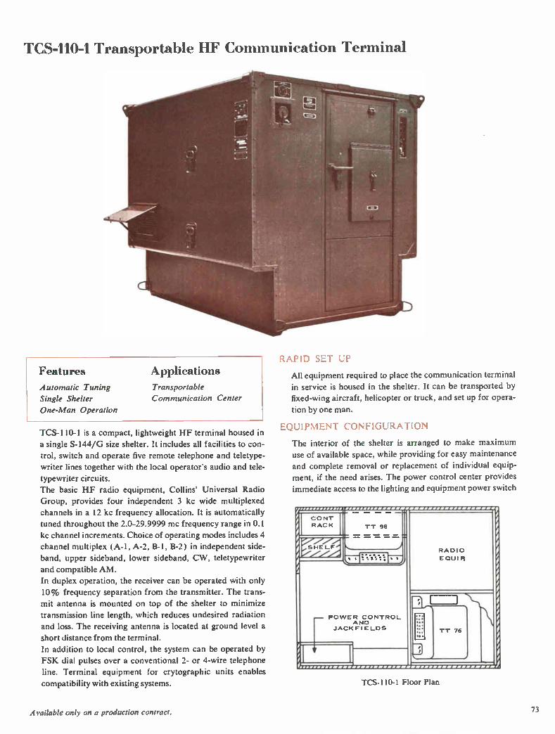
TCS-110-1 Transportable HF Communication Terminal
1.APiD SET UP
Features Applications Automatic Tuning Transportable
Single Shelter Communication Center
One-Man Operation
TCS-110-1 is a compact, lightweight HF terminal housed in
a single S-144/G size shelter. It includes all facilities to con-
trol, switch and operate five remote telephone and teletype-
writer lines together with the local operator's audio and tele-
typewriter circuits.
The basic HF radio equipment, Collins' Universal Radio
Group, provides four independent 3 kc wide multiplexed
channels in a 12 kc frequency allocation. It is automatically
tuned throughout the 2.0-29.9999 mc frequency range in 0.1
kc channel increments. Choice of operating modes includes 4
channel multiplex (A-1, A-2, B-1, B-2) in independent side-
band, upper sideband, lower sideband, CW, teletypewriter
and compatible AM.
In duplex operation, the receiver can be operated with only
10% frequency separation from the transmitter. The trans-
mit antenna is mounted on top of the shelter to minimize
transmission line length, which reduces undesired radiation
and loss. The receiving antenna is located at ground level a
short distance from the terminal.
In addition to local control, the system can be operated by
FSK dial pulses over a conventional 2- or 4-wire telephone
line. Terminal equipment for crytographic units enables
compatibility with existing systems.
All equipment required to place the communication terminal in service is housed in the shelter. It can be transported by
fixed-wing aircraft, helicopter or truck, and set up for opera-
tion by one man.
EQUIPMENT CONFIGURATION
The interior of the shelter is arranged to make maximum
use of available space, while providing for easy maintenance
and complete removal or replacement of individual equip-
ment, if the need arises. The power control center provides
immediate access to the lighting and equipment power switch
CONT
RACK TT 98
st%:1."—r;
POWER CONTROL AND
JACKFIELDS
RADIO
EQUI R
1
TT 76
rrr rr/11 r1r r ¡
TCS-110-1 Floor Plan
Available only on a production contract. 73
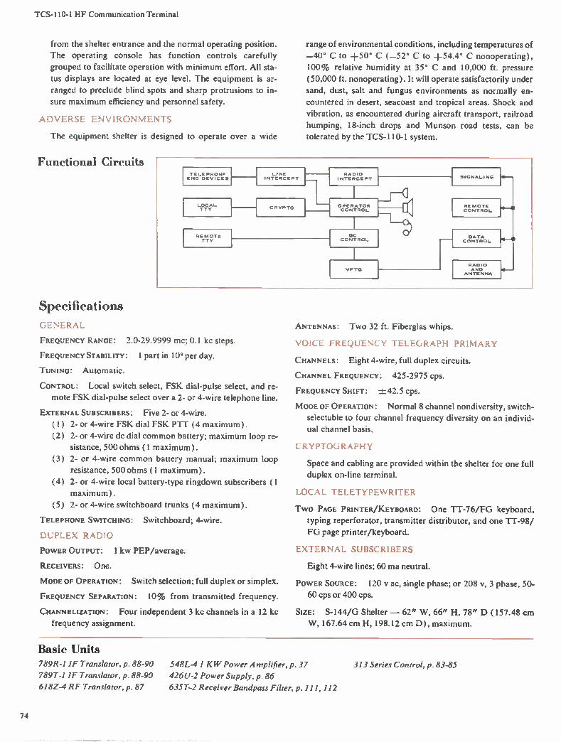
TCS-110-1 HF Communication Terminal
from the shelter entrance and the normal operating position.
The operating console has function controls carefully
grouped to facilitate operation with minimum effort. All sta-
tus displays are located at eye level. The equipment is ar-
ranged to preclude blind spots and sharp protrusions to in-
sure maximum efficiency and personnel safety.
ADVERSE ENVIRONMENTS
The equipment shelter is designed to operate over a wide
Functional Circuits
Specifications
range of environmental conditions, including temperatures of
—40° C to +50° C (-52° C to +54.4° C nonoperating),
100% relative humidity at 35° C and 10,000 ft. pressure
(50,000 ft. nonoperating). It will operate satisfactorily under
sand, dust, salt and fungus environments as normally en-
countered in desert, seacoast and tropical areas. Shock and
vibration, as encountered during aircraft transport, railroad
humping, 18-inch drops and Munson road tests, can be
tolerated by the TCS-110-1 system.
TE LE PHONE END DEVICES
LOCAL TTY
LINE INTERCEPT
REMOTE TTY
CR VP TO
RADIO INTERCEPT
OPERATOR CONTROL
DC CONTROL
VFTG
SIGNALING 10—
REMOTE CONTROL
DATA CONTROL H e
RADIO H AND
ANTENNA
Ci EN ERAL
FREQUENCY RANGE: 2.0-29.9999 mc; 0.1 kc steps.
FREQUENCY STABILITY: 1 part in 10 per day.
TUNING: Automatic.
CONTROL: Local switch select, FSK dial-pulse select, and re-
mote FSK dial-pulse select over a 2- or 4-wire telephone line.
EXTERNAL SUBSCRIBERS: Five 2- or 4-wire.
(1) (2)
(3)
2- or 4-wire FSK dial FSK PTT (4 maximum).
2- or 4-wire dc dial common battery; maximum loop re-
sistance, 500 ohms (1 maximum).
2- or 4-wire common battery manual; maximum loop
resistance, 500 ohms (1 maximum).
(4) 2- or 4-wire local battery-type ringdown subscribers (1
maximum).
2- or 4-wire switchboard trunks (4 maximum). (5)
TELEPHONE SWITCHING: Switchboard; 4-wire.
DUPLEX RADIO
POWER OUTPUT: 1 kw PEP/average.
RECEIVERS: One.
MODE OF OPERATION: Switch selection; full duplex or simplex.
FREQUENCY SEPARATION: 10% from transmitted frequency.
CHANNELIZATION: Four independent 3 kc channels in a 12 kc
frequency assignment.
ANTENNAS: Two 32 ft. Fiberglas whips.
VOICE FREQUENCY TELEGRAPH PRIMARY
CHANNELS: Eight 4-wire, full duplex circuits.
CHANNEL FREQUENCY: 425-2975 cps.
FREQUENCY SHIFT: ±-42.5 cps.
MODE OF OPERATION: Normal 8 channel nondiversity, switch-
selectable to four channel frequency diversity on an individ-
ual channel basis.
CRYPTOGRAPHY
Space and cabling are provided within the shelter for one full
duplex on-line terminal.
LOCAL TELETYPEWRITER
TWO PAGE PRINTER/KEYBOARD: One TT-76/FG keyboard,
typing reperforator, transmitter distributor, and one TT-98/
FG page printer/keyboard.
EXTERNAL SUBSCRIBERS
Eight 4-wire lines; 60 ma neutral.
POWER SOURCE: 120 V ac, single phase; or 208 v, 3 phase, 50-
60 cps or 400 cps.
SIZE: S-144/G Shelter — 62" W, 66" H, 78" D (157.48 cm
W, 167.64 cm H, 198.12 cm D), maximum.
Basic Units 789R-I IF Translator, p. 88-90
789T-1 IF Translator, p. 88-90
618Z-4 RF Translator, p. 87
548L-4 I KW Power A tnplifier, p. 37
426U-2 Power Supply, p. 86
635T-2 Receiver Bandpass Filter, p. 111, 112
313 Series Control, p. 83-85
74
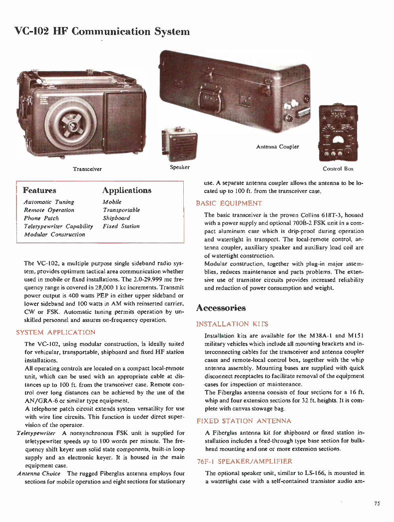
VC-102 HF Communication System
Speaker Transceiver
Features
Automatic Tuning
Remote Operation
Phone Patch
Teletypewriter Capability
Modular Construction
Applications
Mobile
Transportable
Shipboard
Fixed Station
The VC-102, a multiple purpose single sideband radio sys-
tem, provides optimum tactical area communication whether
used in mobile or fixed installations. The 2.0-29.999 mc fre-
quency range is covered in 28,000 1 kc increments. Transmit
power output is 400 watts PEP in either upper sideband or
lower sideband and 100 watts in AM with reinserted carrier,
CW or FSK. Automatic tuning permits operation by un-
skilled personnel and assures on-frequency operation.
SYSTEM APPLICATION
The VC-102, using modular construction, is ideally suited
for vehicular, transportable, shipboard and fixed HF station
installations.
All operating controls are located on a compact local-remote
unit, which can be used with an appropriate cable at dis-
tances up to 100 ft. from the transceiver case. Remote con-trol over long distances can be achieved by the use of the
AN/GRA-6 or similar type equipment.
A telephone patch circuit extends system versatility for use
with wire line circuits. This function is under direct super-
vision of the operator.
Teletypewriter A nonsynchronous FSK unit is supplied for
teletypewriter speeds up to 100 words per minute. The fre-
quency shift keyer uses solid state components, built-in loop
supply and an electronic keyer. It is housed in the main
equipment case.
Antenna Choice The rugged Fiberglas antenna employs four
sections for mobile operation and eight sections for stationary
Antenna Coupler
Control Box
use. A separate antenna coupler allows the antenna to be lo-
cated up to 100 ft. from the transceiver case.
BASIC EQUIPMENT
The basic transceiver is the proven Collins 618T-3, housed
with a power supply and optional 700I3-2 FSK unit in a com-
pact aluminum case which is drip-proof during operation
and watertight in transport. The local-remote control, an-
tenna coupler, auxiliary speaker and auxiliary load coil are
of watertight construction.
Modular construction, together with plug-in major assem-
blies, reduces maintenance and parts problems. The exten-
sive use of transistor circuits provides increased reliability
and reduction of power consumption and weight.
Accessories
INSTALLATION KITS
Installation kits are available for the M38A-1 and M151
military vehicles which include all mounting brackets and in-
terconnecting cables for the transceiver and antenna coupler
cases and remote-local control box, together with the whip
antenna assembly. Mounting bases are supplied with quick
disconnect receptacles to facilitate removal of the equipment
cases for inspection or maintenance.
The Fiberglas antenna consists of four sections for a 16 ft.
whip and four extension sections for 32 ft. heights. It is com-
plete with canvas stowage bag.
FIXED STATION ANTENNA
A Fiberglas antenna kit for shipboard or fixed station in-
stallation includes a feed-through type base section for bulk-
head mounting and one or more extension sections.
76F-1 SPEAKER/AMPLIFIER
The optional speaker unit, similar to LS-166, is mounted in
a watertight case with a self-contained transistor audio am-
75

VC-102 HF Communication System
plifier. A gain control is provided on the side of the enclosure.
690D-1 LOAD COIL
The optional load coil unit is used to electrically lengthen a
16 ft. whip antenna in the 2-30 mc range. It is mounted in a
watertight case which also provides the antenna mount.
Functional Circuits
+28V
coax fitting UG-680/U type N is provided on the side of the
case for connecting a dipole antenna.
CABLES
Optional cables 100 ft. long are available for the control and
A antenna coupler.
6I8T-3 TRANSCEIVER
426T-1 POWER SUPPLY
700B-2 TTY CONV
OSC
718F-1 TRANSCEIVER CASE
400 CPS TTY
POWER
TTY KEY LOOP LINE
RECEIVE COAXIAL CABLE
TRANSMIT COAXIAL CABLE
COUPLER CONTROL
I 1 600 OHM PHONE LI NE
CABLES MAY BE UP TO 100 FT LONG
CABLE MAY BE UP TO 100 FT LONG
1 SPEAKER
..111.. OUTPUT
490B-1 ANTENNA COUPLER
313V-1 CONTROL UNIT
HANDSET KEY HEADSET REMOTE CONTROL AN/GRA-6
Specifications
FREQUENCY RANGE: 2.0-29.999 MC.
NUMBER OF FREQUENCY CHANNELS: 28,000 spaced 1 kc.
FREQUENCY SELECTION: 4 knobs with digital indicators.
TUNING METHOD: Automatic, servo-controlled, including an-tenna coupler.
CHANNEL CHANGE TIME: 15 seconds nominal, including an-
tenna coupler.
OPERATING MODES: USB, LSB, AM, CW and FSK.
FREQUENCY STABILITY: 0.8 part in 1C; per month.
SEMIREMOTE CAPABILITY: Complete control with appropriate
cable up to 100 ft.
REMOTE CAPABILI.TY: Control over 2-wire line with AN/
GRA-6 or equivalent. (Push-to-talk and audio control only, 2 miles.)
ANTENNA REQUIRED: 16 ft. or 32 ft. whip, or 45-90 ft. wire.
PHONE PATCH REQUIREMENTS: 600 ohm phone line operator
controlled, not voice operated.
MICROPHONE: Differential carbon, Electro-Voice 205KK or
equivalent.
KEY: Standard military type.
HANDSET: Military type H33F/PT or equivalent.
POWER INPUT: 27.5 y dc, 53 amps peak during tuning; 37
amps nominal SSB voice transmit; 14 amps receive.
GFE EQUIPMENT: AN/GRA-6 remote control, if used.
SIZE AND WEIGHT: Size H
Weight D
Transceiver 191/2 " 123/4 " 30" 140 lbs. case 49.5 cm 32.4 cm 76.2 cm 63.5 kg
Coupler 9 5/16" 9" 27" 50 lbs. case 23.65 cm 22.8 cm 68.6 cm 22.7 kg
Control box
6" 9" 3.5" 7.5 lbs. 15.2 cm 22.8 cm 8.9 cm 3.4 kg
71/2 " 7" 43/4 " 3.5 lbs. Speaker 19.0 cm 17.8 cm 12.1 cm 1.6 kg
Basic Unit Related Equipment
618T-3 Transceiver, p. 44, 45 7008-2 Teletypewriter Converter, p. 122, 123
76

VC-104 Vehicular HF-UHF Communication System
Features
Automatic Tuning
HF-UHF Communication
Phone Patch
Remote Operation
Modular Construction
Applications
Mobile
Airlift Capability
The VC-104, installed in a 4 x 4 1/4 -ton M38A-1 military ve-
hicle, provides optimum tactical mobile communication in
the 2.0-29.999 mc and 225.0-399.9 mc frequency ranges.
In the HF range, 1 kc channel increments are provided with
400 watts PEP level output in either upper sideband, or low-
er sideband and 100 watt output level in AM with reinserted
carrier, CW or FSK.
The UHF range is covered in 100 kc increments with 20
watts AM output power.
Automatic digital tuning reduces required operator profi-
ciency and precludes the possibility of equipment damage
because of operator error. A separate UHF single frequency
receiver is included to monitor the guard channel.
Available only on a production contract. 77

VC-104 Vehicular HF-UHF Communication System
EQUIPMENT CONFIGURATION
The basic communication equipment, a Collins VC-102 sys-
tem for HF SSB, compatible AM, CW and FSK, and a Col-
lins 718M-1, which includes an AN/ARC-52X for UHF
voice, are housed in compact aluminum cases. The cases
are drip-proof during operation and watertight in the trans-
port condition. The M38A- I vehicle is equipped with a stand-
ard military 100 amp, 27.5 y electrical system.
The primary power system includes a voltmeter/tachometer
to assure correct engine speeds and generating capacity under
all conditions. Both the HF and UHF systems can be oper-
ated while the vehicle is in motion.
Carrying racks are included for transporting AN/PRC-25,
AN/PRC-41 and AN/PRC-47 pack sets. The VC-104 is
well-suited for airlift and airdrop operations because of small
size, reduced weight and ruggedness.
A phone patch circuit extends system versatility for use with
wire line facilities. This function is under direct supervision of the operator.
CONTROLS
All HF operating function controls are located on a compact
local-remote unit which can be quickly detached from the
transceiver case. The VC-104 can be used with an appropri-
ate cable at distances up to 100 ft. from the vehicle. Remote
control over greater distances can be accomplished by the use of the AN/GRA-6 or similar equipment.
In addition to manual selection of the 1750 channels, 19 of
the most commonly used UHF frequencies can be preset,
allowing rapid channel selection. The AN/GRA-6 will also
control the 718M-1 UHF Transceiver.
Controls are centrally located. The HF control unit may be quickly detached for semi-remote operation.
OPTIONAL FSK
One hundred word per minute FSK capability can be added
to the HF system by the use of a Collins 700B-2 Teletype-
writer Converter.
ANTENNA CHOICE
Remote location of the HF antenna is made possible by a sep-
arate antenna coupler which can be positioned up to 100 ft.
from the vehicle. A connector located on the HF whip
mounting base permits the use of a dipole antenna. A discone
UHF antenna mounts directly on the vehicle.
Specifications HF SYSTEM CHARACTERISTICS
POWER OUTPUT: SSB — 400 watts PEP; AM — 100 watts; CW, FSK —100 watts.
FREQUENCY RANGE: 2.0-29.999 mc; 1 kc channel increments.
FREQUENCY STABILITY: 0.8 part in 106 per month.
ANTENNA: Whip, adjustable in sections 16-32 ft. Long wire,
45-90 ft., or dipole antenna can be used.
PHONE PATCH: 600 ohm line.
POWER INPUT: 27.5 y dc; 53 amps peak during tuning; 37
amps nominal SSB voice transmit; 14 amps receive.
WEIGHT: 200 lbs. (90.72 kg).
UHF SYSTEM CHARACTERISTICS
POWER OUTPUT:
FREQUENCY RANGE:
20 watts.
225.0-399.9 mc; 100 kc increments.
FREQUENCY STABILITY: 71- 10 kc.
PRESET CHANNELS: 19, including guard channel.
ANTENNA: AS-390 with 4 each 4 ft. mast sections.
POWER INPUT: 27.5 y dc; 16 amps tuning; 14 amps transmit;
9 amps receive.
WEIGHT: 125 lbs. (56.70 kg).
GFE EQUIPMENT: M38A-1 vehicle and 100 amp generating
system. AN/GRA-6 remote control, if used.
Basic Unit
VC-102 HF Communication System, p. 75,76
Related Equipment
7008-2 Teletypewriter Converter, p. 122, 123
78
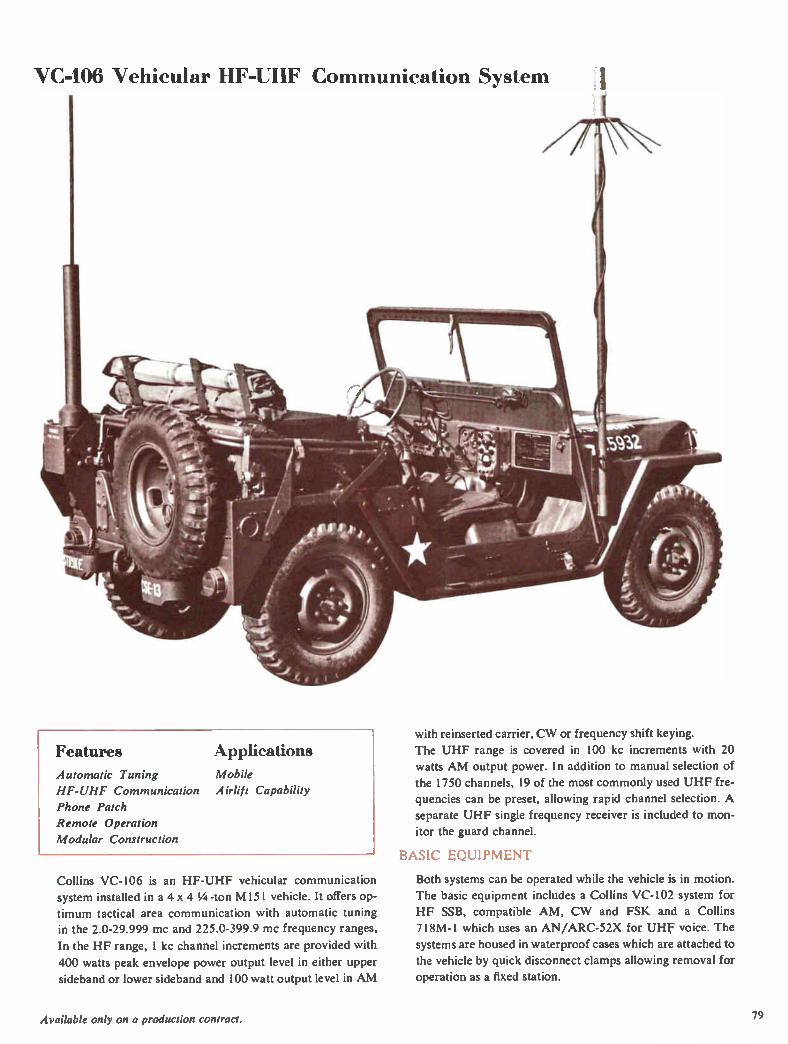
VC-106 Vehicular HF-UHF Communication System
Features Applications
Automatic Tuning Mobile
HF-UHF Communication Airlift Capability
Phone Patch
Remote Operation
Modular Construction
Collins VC-106 is an HF-UHF vehicular communication
system installed in a 4 x 4 1/4 -ton M151 vehicle. It offers op-
timum tactical area communication with automatic tuning in the 2.0-29.999 mc and 225.0-399.9 mc frequency ranges,
In the HF range, 1 kc channel increments are provided with
400 watts peak envelope power output level in either upper
sideband or lower sideband and 100 watt output level in AM
with reinserted carrier, CW or frequency shift keying.
The UHF range is covered in 100 kc increments with 20
watts AM output power. In addition to manual selection of
the 1750 channels, 19 of the most commonly used UHF fre-
quencies can be preset, allowing rapid channel selection. A
separate UHF single frequency receiver is included to mon-
itor the guard channel.
BASIC EQUIPMENT
Both systems can be operated while the vehicle is in motion.
The basic equipment includes a Collins VC-102 system for
HF SSB, compatible AM, CW and FSK and a Collins
718M- I which uses an AN/ARC-52X for UHF voice. The
systems are housed in waterproof cases which are attached to
the vehicle by quick disconnect clamps allowing removal for
operation as a fixed station.
Available only on a production contract. 79
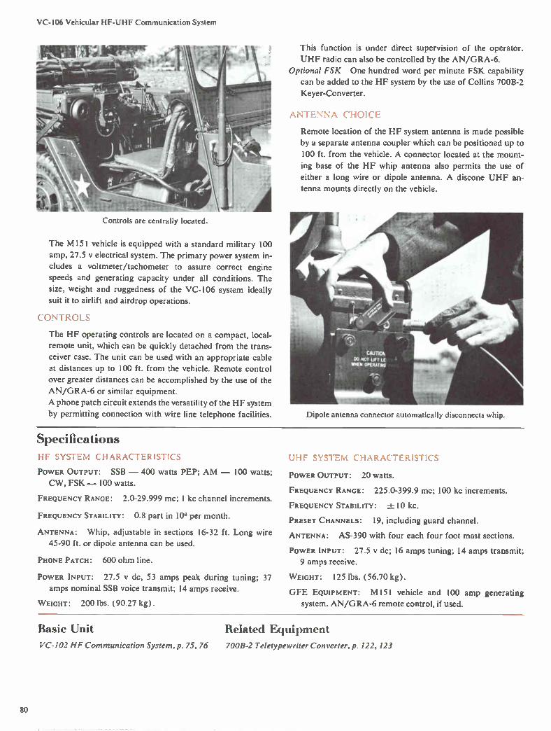
VC-106 Vehicular HF-UHF Communication System
Controls are centrally located.
This function is under direct supervision of the operator.
UHF radio can also be controlled by the AN/GRA-6.
Optional FSK One hundred word per minute FSK capability
can be added to the HF system by the use of Collins 700B-2
Keyer-Converter.
AN1, (— f-ID1(=F:
Remote location of the HF system antenna is made possible
by a separate antenna coupler which can be positioned up to
100 ft. from the vehicle. A connector located at the mount-
ing base of the HF whip antenna also permits the use of
either a long wire or dipole antenna. A discone UHF an-
tenna mounts directly on the vehicle.
The M151 vehicle is equipped with a standard military 100
amp, 27.5 y electrical system. The primary power system in-
cludes a voltmeter/tachometer to assure correct engine
speeds and generating capacity under all conditions. The
size, weight and ruggedness of the VC-106 system ideally
suit it to airlift and airdrop operations.
CONTROLS
The HF operating controls are located on a compact, local-
remote unit, which can be quickly detached from the trans-
ceiver case. The unit can be used with an appropriate cable
at distances up to 100 ft. from the vehicle. Remote control
over greater distances can be accomplished by the use of the
AN/GRA-6 or similar equipment.
A phone patch circuit extends the versatility of the HF system
by permitting connection with wire line telephone facilities. Dipole antenna connector automatically disconnects whip.
Specifications HF SYSTEM CHARACTERISTICS
POWER OUTPUT: SSB — 400 watts PEP; AM — 100 watts;
CW, FSK — 100 watts.
FREQUENCY RANGE: 2.0-29.999 mc; 1 kc channel increments.
FREQUENCY STABILITY: 0.8 part in 106 per month.
ANTENNA: Whip, adjustable in sections 16-32 ft. Long wire
45-90 ft. or dipole antenna can be used.
PHONE PATCH: 600 ohm line.
POWER INPUT: 27.5 y dc, 53 amps peak during tuning; 37
amps nominal SSB voice transmit; 14 amps receive.
W EIGHT: 200 lbs. (90.27 kg).
UHF SYSTEM CHARACTERISTICS
POWER OUTPUT: 20 watts.
FREQUENCY RANGE: 225.0-399.9 mc; 100 kc increments.
FREQUENCY STABILITY: -4- 10 kc.
PRESET CHANNELS: 19, including guard channel.
ANTENNA: AS-390 with four each four foot mast sections.
POWER INPUT: 27.5 y dc; 16 amps tuning; 14 amps transmit;
9 amps receive.
W EIGHT: 125 lbs. (56.70 kg).
GFE EQUIPMENT: M151 vehicle and 100 amp generating
system. AN/GRA-6 remote control, if used.
Basie Unit Related Equipment VC-IO2 HF Communication System, p. 75,76 7008-2 Teletypewriter Converter, p. 122, 123
80

Universal Radio Group The Collins Universal Radio Group is an advanced line of automatically tuned }IF communication equipment based upon a building block concept which gives it a new degree of flexibility, ver-satility and logistic commonality.
Units can be selected to provide trans-mitters, receivers or transceivers with local, remote or dial telephone control capabilities. URG equipment is equally well suited for fixed station, transport-
able, shipboard and airborne applica-tions — and without the extra fabrica-tion costs and long lead time normally involved in tailoring equipment for these installations. The equipment is of a modular design, with the smaller units housed in AR1NC (Aeronautical Radio, Inc.) type en-closures. Shelves of this equipment, as well as the larger power amplifiers, are mounted in rugged Unistrut racks with optional enclosure panels. Attractive racks, cabinets and shelves are avail-able to meet a wide variety of applica-tion requirements.
d II1EV WIRE LINE REMOTE
I CONTROL '
TRANSCEIVER
CONTROL UNIT
POWER AMPLIFIER
ANTENNA COUPLER

40N-1,-2 Frequency Standards
Features Applications Frequency Accuracy
Amplitude Stability
Minimum Harmonics
Centralized Metering
Fixed Station
Shipboard
Data Transmission
The 40N-1,-2 Frequency Standards provide 1 mc, 100 kc
and 10 kc outputs with no appreciable harmonics and a sta-
bility of one part in 10 per day minimum. They are excellent
for supplying reference signals in a wide range of fixed sta-
tion and shipboard applications.
Both standards are particularly suited for use with HF re-
ceivers and exciters, such as Collins' AN/URC-32 and Col-
lins' Universal Radio Group equipment. The 40N- 1,-2 are
equally suited for use in laboratories or other communica-
tion systems as base frequency standards.
The 40N-1 consists of three rack mounted units — a 40K-1
Oscillator, which generates the highly stable 1 mc signal;
an 8U-1 Frequency Divider, which supplies simultaneous
1 mc, 100 kc and 10 kc outputs from the basic 1 mc signal;
and a 426A-1 Power Supply.
The 40N-2 is a dual frequency standard which includes three
40K-1's, two 8U-1's and a 54M-1 Frequency Comparator,
together with associated 426A-I Power Supplies. The output
signals of the 40K-1 Oscillators are compared in the 54M-1,
and any two of the three can be selected independently, per-
mitting maximum assurance of frequency accuracy. The dif-
ference between any two signals is indicated on a front panel
meter or through headphones.
The use of a rugged 1 mc resonator at low power levels, rath-
er than the conventional 100 kc circuit, eliminates normal
susceptibility to shock.
Both the 40N-1 and 40N-2 mount in 19" equipment racks,
and all units are of matching mechanical design. All power
and coaxial RF cables terminate at the rear of the units.
Tubes and adjustments are accessible from the front of each
unit by removing the snap-on dust cover.
Specificat ions
FREQUENCY STABILITY: One part in 108 per day
one part in 10' per day typical.
OUTPUT: 1 MC — 0-2 y rms. 100 kc — 0-5 y rms. 10 kc —
0-5 y rms. 40N- I — one independent frequency. 40N-2 —
best two of three independent frequencies.
Ouretrr IMPEDANCE: 500 ohms nominal. BNC connectors.
minimum;
POWER REQUIREMENTS: 115 V or 230 1/, 50-60 cps.
SIZE AND WEIGHT (excluding rack) :
Size Weight
H D
40N-1 19" 2244" 7" 66 lbs. 48.26 cm 57.59 cm 17.78 cm 29.94 kg
40N-2 19" 79" 7" 190 lbs. 48.26 cm 200.66 cm 17.78 cm 86.18 kg
82

3133-2, 313K-2 and 313L-1 Control Equipment
3131-2 Dial Pulse Control 3I3K-2 Allotter-Preset
Features
Dial-Pulse Control
Installation Flexibility
Modular Construction
Telephone Compatibility
Complete Remote Operation
Applications
Fixed Station
Transportable
The 313J-2, 3I3K-2 and 313L-1 Control Units allow com-
plete remote operation of an unattended URG installation
over landlines, microwave or a radio link by simple telephone
dialing. The control units are part of the Collins Universal
Radio Group, a family of integrated building block equip-
ment which permits a selection of units to meet a specific
communication requirement. In addition to fixed station ap-
plication it is suitable for transportable systems, such as the
AN/TSC-38.
SIMPLIFIED OPERATION
By dialing the proper predetermined number code groups,
the operator can turn on and off the primary power to the
3 13Q-I Control Uni,
313L-1 Frequency Register
equipment, select such functions as operating frequency,
mode, receiver gain, transmitter power levels, and can choose
an antenna and antenna azimuth if steerable antenna is em-
ployed. Other functions are also available as options in the
URG equipment.
An automatic switchboard can be used in a radio-telephone
exchange system to interconnect with audio circuits originat-
ing from either landline or radio to the HF URG facilities.
Subscriber control of the system can be effected from any
of the connected dial telephones.
PRESET CHANNELS
The most frequently used radio conditions on a particular
channel are available by simply lifting the subscriber's hand-
set from its base. The 313K-2 stores preset operating infor-
mation for ten specified operating conditions which can be
applied to any of four radio channels. If the channel is in use,
it will not handle a request until termination of processing
the previous request.
The normal-preset channel can be obtained from a 714Y, a
local manual control unit, or one of the presets in the 3I3K-2,
depending on the interconnection of control equipment. The
83
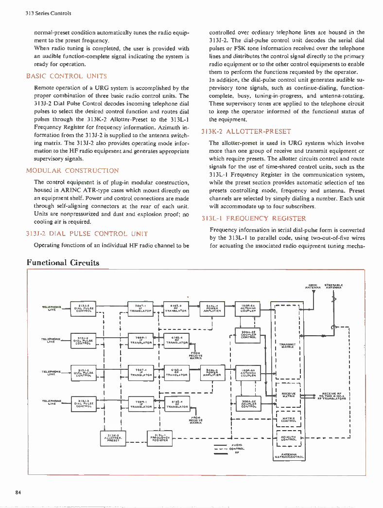
313 Series Controls
normal-preset condition automatically tunes the radio equip-
ment to the preset frequency.
When radio tuning is completed, the user is provided with
an audible function-complete signal indicating the system is
ready for operation.
BASIC CONTROL UNITS
Remote operation of a URG system is accomplished by the
proper combination of three basic radio control units. The
313J-2 Dial Pulse Control decodes incoming telephone dial
pulses to select the desired control function and routes dial
pulses through the 313K-2 Allotter-Preset to the 313L-1
Frequency Register for frequency information. Azimuth in-
formation from the 313J-2 is supplied to the antenna switch-
ing matrix. The 313J-2 also provides operating mode infor-
mation to the HF radio equipment and generates appropriate supervisory signals.
MODULAR CONSTRUCTION
The control equipment is of plug-in modular construction, housed in ARINC ATR-type cases which mount directly on
an equipment shelf. Power and control connections are made
through self-aligning connectors at the rear of each unit.
Units are nonpressurized and dust and explosion proof; no
cooling air is required.
313J-2 DIAL PULSE CONTROL UNIT
Operating functions of an individual HF radio channel to be
Functional Circuits
controlled over ordinary telephone lines are housed in the
3131-2. The dial-pulse control unit decodes the serial dial
pulses or FSK tone information received over the telephone
lines and distributes the control signal directly to the primary
radio equipment or to the other control equipments to enable
them to perform the functions requested by the operator.
In addition, the dial-pulse control unit generates audible su-
pervisory tone signals, such as continue-dialing, function-
complete, busy, tuning-in-progress, and antenna-rotating.
These supervisory tones are applied to the telephone circuit
to keep the operator informed of the functional status of
the equipment.
31 3K-2 ALLOTTER-PRESET
The allotter-preset is used in URG systems which involve
more than one group of receive and transmit equipment or
which require presets. The allotter circuits control and route
signals for the use of time-shared control units, such as the
313L-1 Frequency Register in the communication system,
while the preset section provides automatic selection of ten
presets controlling mode, frequency and antenna. Preset
channels are selected by simply dialing a number. Each unit
will accommodate up to four subscribers.
313L- l FREQUENCY REGISTER
Frequency information in serial dial-pulse form is converted
by the 313L- l to parallel code, using two-out-of-five wires
for actuating the associated radio equipment tuning mecha-
KKKKK NONE 313.1 2 DIAL PULSE
LINE CONTROL
TELEPH ONE 313.1.2 L INE DIAL PULSE
CONTROL
KKKKKK ONE 313J•2 D AL PULSE
LINE CONTROL
1
09,T • I
TRANSLATOR
7119R•1
RANSLATOR
TELEPHONE H 313./4 LINE DIAL PULSE
CONTROL
- t--
211212, RF
RANSLATOR POWER
AMPLIFIER
545,4 h.
RISE, RF
TRANSLATOR
709T IF
RANSLATOR 4.
‘--
1 3131,2
ALLOTTER. PRESET
4-
7S9R.I 4 e/.. IF
TRANSLATOR
0.1
FROM RECEIVE MATRIX
RP TRANSLATOR
01E2, '/I9 595L•9 POWER
AMPLIFIER
6181,
TRANSLATOR
313L•I FREQUENCY REGISTER
FROM RECEIVE MATRIX
leOR SA ANTENNA COUPLER
309A•2E COUPLER CONTROL
IIIOR•eA NTENNA
COUPLER
TRANSMIT MATRIX
OMNI STEERAEILIE ANTENNA ANTENNA
---r-; r ----1 1
' ---.1 lee =.;42j:11:iie. Hi- 1 _ ..... -I
1 1 CMOANTTRRIOX L 1
L__ _ _J r- - - -1 1 geRra F-L__ __I
309A•2E COUPLER CONTROL
AUDIO
CONTROL
RP ANTENNA
MATRIX/CONTROL
84

313 Series Controls
nisms. The frequency register output circuits are armed by a
signal from the 313K-2 Allotter-Preset unit, with subsequent
dial pulses representing the frequency information. Frequen-
cy requests outside of the 2.0-29.999 mc range will actuate
a busy signal. In a typical system, the 3I3L is available to in-
dividual channels on a time-shared or demand basis.
Typical URG System Control Codes
FUNCTION
Steerable antenna
selection
Omni antenna
selection
Frequency
selection
Mode selection:
Sideband selection
Twin sideband
selection
Power ON-OFF
AM selection
RF gain selection
Power level
selection
Preset selection
Miscellaneous I*
DIALED CODE ON INPUT
TELEPHONE PAIR
Two digits indicating the desired azi-
muth in 30° steps, 03, 06, 09, 12, 15, 18,
21, 24, 27, 30, 33, 36.
Digit 4 plus digit 1.
Digit 5 plus the digits of the desired fre-
quency. In 100 cycle. steps, 020,000 to
299,999.
Digit 6 plus digit I for USB or digit 2
for LSB.
Digit 6 plus digit 3.
Digit 6 plus digit 0 for off or digit 9 for
on.
Digit 6 plus digit 4.
Digit 6 plus digit 5 for low gain or digit
6 for high gain.
Digit 6 plus digit 7 for low power or
digit 8 for high power.
Digit 7 plus any digit from 0 to 9 repre-
senting the number of the preset de-
sired.
Digit 8 plus the digits of the desired fre-
quency. In 100 cycle steps, 020,000 to
299,999.
Miscellaneous 2* Digit 9 plus any digit from 0 to 9 repre-
senting the number of the preset de-
sired.
*Option: For duplex operation, the digit 8 will be used for
transmitter frequency selection and the digit 9 for trans-
mitter preset selection.
3130-1 CONTROL UNIT
The 313Q-I permits manually switched selection of frequen-
cy and mode of transmission, on-off control, and gain control
of four different transceivers in a system using the 313J,
313K and 313L remote control equipments. All the super-
visory tones present in the automatic system serve the same
functions in an installation using the 313Q-1 Control Unit.
Selection of any of 280,000 channels with 0.1 kc spacing over
the 2.0-29.9999 mc range is indicated by a direct, digital
readout of the operating frequency. All frequency selection
terminations are diode isolated for 500 ma current to allow
paralleling of control units.
The 313Q- I Control is part of the Collins Universal Radio
Group, a family of HF building block equipment which offers
a choice of units to meet any communication requirement.
Size: 1/2 ATR; 5" W, 7 11/16" H, 10 3/32" D (12.7 cm W,
19.53 cm H, 25.64 cm D), Weight: 6 lbs. (2.72 kg).
Specifications
POWER REQUIREMENTS (maximum):
3131-2 Dial Pulse Control
3 I 3K-2 Allotter-Preset
3 I 3L-1 Frequency Register
SIZE AND W EIGHT:
Size H
27.5 y dc, 5 amps
27.5 y dc, 2 amps
27.5 y dc, 2 amps
D Weight
313J-2 7318" 19 9/16" 27 1/2 lbs. dial pulse 12.38 cm 19.37 cm 49.69 cm 12.47 kg control
3I3K-2 47/s" 75/8" 19 9/16" 19 lbs. allotter- 12.38 cm 19.37 cm 49.69 cm 8.62 kg preset
313L-1 21/4 " 75/ii" 19 9/16" frequency 5.72 cm 19.37 cm 49.69 cm register
14 lbs. 6.35 kg
Related Equipment Racks and Cabinets, p.91
85

426C-2 27.5 N DC Power Suppl>
Specifications Features Applications
AC or DC Input
Adjustable Output
Excellent Regulation
Parallel Operation
Solid State
Circuit Protection
Fixed Station
Transportable
Shipboard
Mobile
Airborne
The 426U-2 is a compact, lightweight power supply which
provides 27.5 v, 100 amps nominal dc output from a variety
of ac or dc power sources. A variable output current limit
control provides maximum current settings between 75 amps
and 125 amps. Any number of 426U-2 Power Supplies can
be operated in parallel.
APPLICATION
The 426U-2 is part of the Collins Universal Radio Group of
HF equipments and is intended for use with the 548L-4
Power Amplifier. It is also well suited for use with other
equipments requiring a 27.5 y highly regulated, high current
input. The unit can be installed either in a Unistrut equipment
rack or an attractive cabinet enclosure.
HIGH RELIABILITY
Solid state components are used throughout for minimum
size and maximum reliability. Protective circuits include
overload, undervoltage and loss of cooling air, together with
fault indicator and remote alarm. The 426U-2 will not be
damaged during current overload or short circuit conditions,
and normal system operation is quickly restored when the
overload is removed.
INSTALLATION
The 426U-2 mounts in an externally cooled, ARINC Specifi-
cation 404, I ATR tray. All power terminations are made
through a single rear connector. The washable air filter, test
points, over-current control and output voltage control are
accessible by removing the front panel insert.
INPUT POWER: 90-140 v, line to neutral ac, 45-450 cps, single
phase 3-wire, or 3 phase 4-wire; or 90-140 v dc. Overvoltage
may be 150 1/, line to neutral ac for 90 milliseconds maxi-
mum duration. Undervoltage to 0 level without damage to
the power supply.
OUTPUT VOLTAGE: 27.5 y dc nominal, 100 amps.
VOLTAGE CONTROL: Continuously variable from 24-29 y dc.
VOLTAGE REGULATION: 0.5 v from 0-100 amps.
RIPPLE VOLTAGE: Less than 0.25 y rms from 5-100 amps.
LOAD TRANSIENTS: Less than ±- 1.5 y output variation for a
step of 15-90 amps or 90-15 amps.
OVERVOLTAGE: Power supply will shut off if output voltage
exceeds 33 y ±2 y for 100 milliseconds.
OVERLOAD PROTECTION: Maximum output current adjustable
from 75-125 amps. Overload conditions reduce the output
voltage to a level which limits the current to the overload set-
ting. Normal operation is restored upon removal of overload.
EFFICIENCY: 75% minimum at 100 amps output.
TEMPERATURE RANGE: —40° C to +50° C operating; —62° C
to +85° C nonoperating.
HUMIDITY: 0%-100%, operating or nonoperating.
ALTITUDE: 0-50,000 ft. operating.
COOLING REQUIREMENTS: 220 lbs. per hour minimum with
maximum output over the above temperature range. Requires
150 lbs. per hour at 20°-30° C.
SIZE: 10 1/2" W, 75/8" H, 19 9/16" D (26.67 cm W, 19.37 cm
H, 49.69 cm D).
WEIGHT: 83.5 lbs. (37.88 kg).
Related Equipment Racks and Cabinets, p. 91
548L-4 1 KW Power Amplifier, p. 37
86
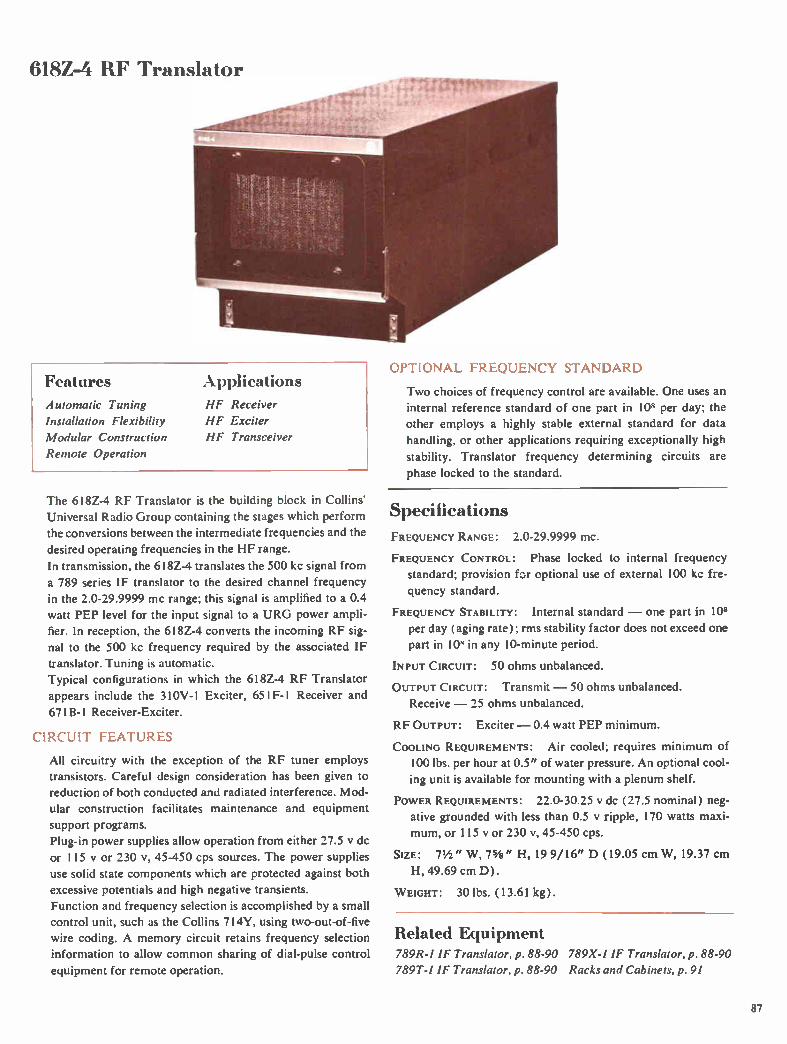
618Z-4 11F Translator
OPTIONAL FREQUENCY STANDARD Features Applications
Automatic Tuning
Installation Flexibility
Modular Construction
Remote Operation
HF Receiver
HF Exciter
HF Transceiver
The 618Z-4 RF Translator is the building block in Collins'
Universal Radio Group containing the stages which perform
the conversions between the intermediate frequencies and the
desired operating frequencies in the HF range.
In transmission, the 618Z-4 translates the 500 kc signal from
a 789 series IF translator to the desired channel frequency
in the 2.0-29.9999 mc range; this signal is amplified to a 0.4
watt PEP level for the input signal to a URG power ampli-
fier. In reception, the 6I8Z-4 converts the incoming RF sig-
nal to the 500 kc frequency required by the associated IF
translator. Tuning is automatic.
Typical configurations in which the 618Z-4 RF Translator
appears include the 310V- l Exciter, 651F-I Receiver and
671B-1 Receiver-Exciter.
CIRCUIT FEATURES
All circuitry with the exception of the RF tuner employs transistors. Careful design consideration has been given to
reduction of both conducted and radiated interference. Mod-
ular construction facilitates maintenance and equipment
support programs.
Plug-in power supplies allow operation from either 27.5 y dc
or 115 y or 230 II, 45-450 cps sources. The power supplies
use solid state components which are protected against both
excessive potentials and high negative transients.
Function and frequency selection is accomplished by a small
control unit, such as the Collins 714Y, using two-out-of-five
wire coding. A memory circuit retains frequency selection
information to allow common sharing of dial-pulse control
equipment for remote operation.
Two choices of frequency control are available. One uses an
internal reference standard of one part in 10" per day; the
other employs a highly stable external standard for data
handling, or other applications requiring exceptionally high
stability. Translator frequency determining circuits are
phase locked to the standard.
Specifications
FREQUENCY RANGE: 2.0-29.9999 mc.
FREQUENCY CONTROL: Phase locked to internal frequency
standard; provision for optional use of external 100 kc fre-
quency standard.
FREQUENCY STABILITY: Internal standard — one part in 108
per day ( aging rate); rms stability factor does not exceed one
part in 10" in any 10-minute period.
INPUT CIRCUIT: 50 ohms unbalanced.
OUTPUT CIRCUIT: Transmit — 50 ohms unbalanced.
Receive — 25 ohms unbalanced.
RF OUTPUT: Exciter — 0.4 watt PEP minimum.
COOLING REQUIREMENTS: Air cooled; requires minimum of
100 lbs. per hour at 0.5" of water pressure. An optional cool-
ing unit is available for mounting with a plenum shelf.
POWER REQUIREMENTS: 22.0-30.25 y dc (27.5 nominal) neg-
ative grounded with less than 0.5 y ripple, 170 watts maxi-
mum, or 115 y or 230 v, 45-450 cps.
SIZE: 7½" W, 75/s " H, 19 9/16" D (19.05 cm W, 19.37 cm
H, 49.69 cm D).
WEIGHT: 30 lbs. (13.61 kg).
Related Equipment 789R-1 IF Translator, p. 88-90 789X-1 IF Translator, p. 88-90
789T-I IF Translator, p. 88-90 Racks and Cabinets, p. 91
87
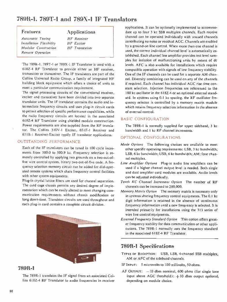
78911-1, 789T-I and 789k-1 IF Translators
Features Applications Automatic Tuning
Installation Flexibility
Modular Construction
Remote Operation
HF Receiver
HF Exciter
HF Transceiver
The 789R-I, 789T-1 or 789X-1 IF Translator is used with a
618Z-4 RF Translator to provide either an HF receiver,
transmitter or transceiver. The IF translators are part of the
Collins Universal Radio Group, a family of integrated HF
building block equipment which offers a choice of units to
meet a particular communication requirement.
The signal processing circuits of the conventional receiver,
exciter and transceiver have been divided into two separate
translator units. The IF translator contains the audio and in-
termediate frequency circuits and uses plug-in circuit cards
to permit selection of specific performance capabilities, while
the radio frequency circuits are located in the associated
618Z-4 RF Translator using shielded module construction.
Power requirements are also supplied from the RF transla-
tor. The Collins 3I0V- I Exciter, 651F-1 Receiver and
67IB- I Receiver-Exciter typify IF translator applications.
OUTSTANDING PERFORMANCE
Each of the IF translators can be tuned in 100 cycle incre-ments from 500.0 to 500.9 kc. Frequency selection is re-
motely controlled by applying two grounds on a two-out-of-
five wire control system, binary two-out-of-five code. A fre-
quency selection memory circuit can be added for dial-oper-
ated remote systems which share frequency control facilities
with other system equipments.
Plug-in crystal lattice filters are used for channel separation.
The card cage chassis permits any desired degree of imple-
mentation which can be easily altered to meet changing com-
munication requirements without chassis modification or
long down-time. Transistor circuits are used throughout and
each plug-in card contains a complete circuit division.
789R-1
The 789R-1 translates the IF signal from an associated Col-
lins 618Z-4 RF Translator to audio frequencies in receiver
applications. It can be optionally implemented to accommo-
date up to four 3 kc SSB multiplex channels. Each receive
channel can be operated individually with unused channels
contributing no noise or residual AGC. Channels are enabled
by a ground-on line control. When more than one channel is
used, the correct individual channel level is automatically es-
tablished. Each channel line amplifier provides test level sam-
ples for isolation of malfunctioning units by means of dc
levels. AFC is also available for installations which require
compatible operation with signals of low frequency stability.
One of the IF channels can be used for a separate AM chan-
nel. Diversity combining can be used on any of the channels
if required. Each channel has individual AGC rise time con-
stant selection. Injection frequencies are referenced to the
100 kc oscillator in the 618Z-4 or an optional external stand-
ard. In systems using 0.1 kc spacing, the RF oscillator fre-
quency selector is controlled by a memory matrix module
which retains frequency selection information in the absence
of external control.
BASIC CONFIGURATION
The 789R-1 is normally supplied for upper sideband, 3 kc
bandwidth and 1 kc RF channel increments.
OPTIONAL CONFIGURATIONS
Mode Options The following choices are available to meet
other specific operating requirements: LSB, 3 kc bandwidth;
LSB, 6 kc bandwidth; USB, 6 kc bandwidth; AM: four chan-
nel multiplex.
Line Amplifier Options Plug-in audio line amplifiers can be
used if a higher channel output level is needed. Both single
and dual amplifier card modules are available. Audio levels
can be adjusted individually.
Tenth KC Channel Increment Option The number of RF
channels can be increased to 280,000.
Memory Matrix Option The memory matrix is necessary only
in systems sharing frequency control equipments. The 0.1 kc
digit information is retained in the absence of continuous
frequency information until a new frequency is selected. It is
intended primarily for installations using the 313 series of
wire line control equipments.
External Frequency Standard Option This option offers great-
er frequency stability for data communication or other appli-
cations. The 789R-1 normally uses the frequency standard
in the associated 618Z-4 RF Translator.
789R-1 Specifications
TYPES OF RECEPTION: USB, LSB, 4-channel SSB multiplex,
AM or AFC of the sideband channels.
IF INPUT: 5 microvolts to 100 millivolts, 50 ohms.
AF OUTPUT: —10 dbm nominal, 600 ohms (for single tone
input above AGC threshold); +10 dbm output optional,
depending on module choice.
88

789 Series IF Translators
PRIMARY POWER INPUT: Derived entirely from associated
618Z-4 RF Translator.
SIZE: 1/2 ATR; 4 7/8" W, 75/8" H, 19 9/16" D (12.4 cm W,
19.4 cm H, 49.7 cm D).
W EIGHT: 12 lbs. (5.4 kg) minimum implementation; 18 lbs.
(8.2 kg) fully implemented.
789T-1 The 789T-1 converts audio inputs to the nominal 500 kc IF
signal required by an associated Collins 618Z-4 RF Transla-
tor in transmitter applications. It can be optionally imple-
mented to accommodate up to four 3 kc SSB multiplex chan-
nels. Channels are enabled by a ground-on line control. When
more than one channel is used, the correct individual chan-
nel level is automatically established. Each channel provides test level samples for isolation of malfunctioning units by
means of dc levels. A pilot carrier is available for installations
which require compatible AM operation (AME) or AFC
operation. The transmit gain control and exciter output levels are auto-
matically adjusted. The signal is translated to the nominal 500
kc IF, using injection frequencies stepped in 0.1 kc channel
increments when 280,000 channels are used.
BASIC CONFIGURATION
The 789T-1 is normally supplied for upper sideband, 3 kc
bandwidth and 1 kc RF channel increments.
OPTIONAL CONFIGURATIONS
Mode Options The following choices are available to meet
other specific operating requirements: LSB, 3 kc bandwidth;
LSB, 6 kc bandwidth; USB, 6 kc bandwidth; AM; 4-channel
multiplex.
Tenth KC Channel Increment Option The number of RF
channels can be increased to 280,000.
Line Amplifier Options Plug-in audio line amplifiers can be
used if the audio input is below the required level. Both single
channel and dual channel amplifier card modules are avail-
able. Individual level adjustments are provided.
Memory Matrix Option The memory matrix is necessary only
in systems sharing frequency control information between
equipments. In installations which share frequency control
equipment, the 0.1 kc digit information is retained in the
absence of continuous frequency information until a new
frequency is selected. It is intended primarily for installations
using the 313 series of wire line control equipment.
External Standard Option This option offers greater frequency
stability for data communication or other applications. The
789T-1 normally uses the frequency standard in the associ-
ated 618Z-4 RF Translator.
789T-1 Specifications
EmISSION: USB, LSB, selectable-level carrier plus USB, LSB or both, compatible AM (USB or LSB plus carrier), 4-chan-
nel SSB multiplex with outboard channels inverted, CW te-
legraphy, audio tone data.
AUDIO INPUT: Single test tone —26 dbm nominal; voice —34
VU nominal, 600 ohms, with line amplifiers.
IF OUTPUT: 20 peak millivolts maximum, 50 ohms.
PRIMARY POWER INPUT: Derived entirely from associated
618Z-4 RF Translator.
SIZE: 1/2 ATR; 4 7/8" W, 71/4 " H, 19 9/16" D (12.4 cm W,
19.4 cm H, 49.7 cm D).
W EIGHT: 11 lbs. (4.99 kg) minimum implementation; 18 lbs.
(8.2 kg) fully implemented.
789X-1 The 789X-1 is a bilateral IF translator used in conjunction
with a Collins 618Z-4 RF Translator for transceiver applica-
tions. Performance characteristics include 100 cycle channel
increments with nominal 3 kc or 6 kc bandwidths of two SSB
channels or AM. Injection frequencies are referenced to the
100 kc oscillator in the 618Z-4 or an optional external stand-
ard. The RF oscillator frequency selector is controlled by a memory matrix module which retains frequency selection in-
formation in the absence of external control. In transmit
function, the transmit gain control and exciter output levels
are automatically adjusted. Pilot carrier is available for in-
stallations which require compatible AM operation.
BASIC CONFIGURATION
The 789X-1 is normally supplied for upper sideband, 3 kc
89

789 Series IF Translators
bandwidth and 1 kc RF channel increments, with adjustable
pilot carrier reinsertion for compatible AM in transmit.
OPTIONAL CONFIGURATIONS
Mode Options The following choices are available to meet
other specific operating requirements: LSB, 3 kc bandwidth;
LSB, 6 kc bandwidth; USB, 6 kc bandwidth; and AM.
Tenth KC Channel Increment Option The number of RF
channels can be increased to 280,000.
Line Amplifier Options Plug-in audio line amplifiers can be
used on the incoming line in transmit and the audio output in
receive if higher levels are needed. Single input or output line
amplifiers for one-channel systems, as well as dual amplifiers
for systems using channels on both USB or LSB are available.
Memory Matrix Option The memory matrix is necessary only
in systems sharing frequency control information between
equipments. In installations which share frequency control
equipment, the 0.1 kc digit information is retained in the ab-
sence of continuous frequency information until a new fre-
quency is selected. It is intended primarily for installations
using the 313 series of wire line control equipment.
External Frequency Standard Option This option offers ex-
tremely high frequency stability for data communication or
other applications. The 789X- I normally uses the frequency
standard located in the associated 618Z-4 RF Translator.
789X-1 Specifications
MODES: USB with suppressed carrier, LSB with suppressed
carrier, selectable-level carrier plus USB, LSB or both, com-
patible AM ( USB or LSB plus carrier), CW, audio tone data.
AUDIO INPUT (TRANSMIT): Single test tone —26 dbm nominal;
voice —34 VU nominal at 600 ohms, with line amplifiers.
IF OUTPUT (TRANSMIT): 20 peak millivolts maximum, 50
ohm impedance.
IF INPUT (RECEIVE): 5 microvolts to 100 millivolts, 50 ohms.
AUDIO OUTPUT (RECEIVE): —10 to +10 dbm nominal into
600 ohms ( for single tone input above AGC threshold), with
line amplifiers.
PRIMARY POWER INPUT: Derived from associated 618Z-4.
SIZE: 1/2 ATR; 4 7/8" W, 75/8" H, 19 9/16" D (12.4 cm W,
19.4 cm H, 49.7 cm D).
W EIGHT: 12 lbs. (5.4 kg) minimum implementation; 25 lbs.
(11.3 kg) fully implemented.
Related Equipment 618Z-4 RF Translator, p. 87 Racks and Cabinets, p.91
714Y-I,-2 Controls, p.90
7141-1 Control Unit
The 714Y-1 is a panel or console mounted control unit which
permits selection of frequency, operating mode and RF gain
level for a Collins Universal Radio Group receiver, exciter or
exciter-receiver installation. Channel frequencies are indicat-
ed in a direct reading digital readout and can be selected in 1
kc increments throughout the 2.0-29.999 mc range. All fre-
quency selection terminations are diode isolated to permit
paralleling of control units.
Size: 53/4" W, 25/8" H, 6" D ( 14.61 cm W, 6.67 cm H, 15.24
cm D). Weight: 2 lbs. (0.91 kg).
714-1-2 Control Unit
The 714Y-2 is a compact control unit for use with the Collins
Universal Radio Group exciters, receivers or exciter-receiv-
ers. It allows remote selection of any of 280,000 channels
with 0.1 kc spacing over the 2.0-29.9999 mc frequency range.
Thumb-index type knobs provide direct digital readout of
the operating frequency. All frequency selection termina-
tions are diode isolated for 200 ma current to allow parallel-
ing of control units.
Size: 53/4 " W, 2 9/16" H, 6 9/32" D (14.61 cm W, 6.51
cm H, 15.95 cm D). Weight: 1 lb. (0.45 kg).
90
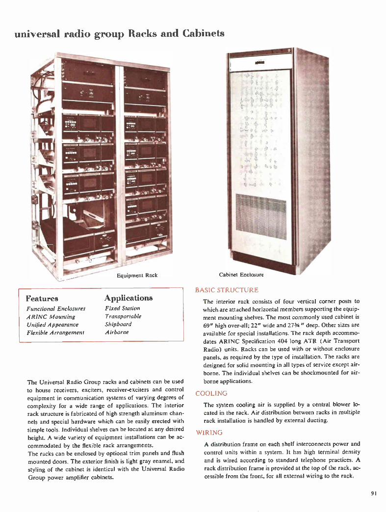
universal radio group Racks and Cabinets
Equipment Rack
Features Applications Functional Enclosures Fixed Station
A RINC Mounting Transportable
Unified Appearance Shipboard
Flexible Arrangement Airborne
The Universal Radio Group racks and cabinets can be used
to house receivers, exciters, receiver-exciters and control
equipment in communication systems of varying degrees of
complexity for a wide range of applications. The interior
rack structure is fabricated of high strength aluminum chan-
nels and special hardware which can be easily erected with
simple tools. Individual shelves can be located at any desired
height. A wide variety of equipment installations can be ac-
commodated by the flexible rack arrangements.
The racks can be enclosed by optional trim panels and flush
mounted doors. The exterior finish is light gray enamel, and
styling of the cabinet is identical with the Universal Radio
Group power amplifier cabinets.
Cabinet Enclosure
BASIC STRUCTURE
The interior rack consists of four vertical corner posts to
which are attached horizontal members supporting the equip-
ment mounting shelves. The most commonly used cabinet is
69" high over-all; 22" wide and 273/4 " deep. Other sizes are
available for special installations. The rack depth accommo-
dates ARINC Specification 404 long ATR (Air Transport
Radio) units. Racks can be used with or without enclosure panels, as required by the type of installation. The racks are
designed for solid mounting in all types of service except air-
borne. The individual shelves can be shockmounted for air-
borne applications.
COOLING
The system cooling air is supplied by a central blower lo-
cated in the rack. Air distribution between racks in multiple
rack installation is handled by external ducting.
WIRING
A distribution frame on each shelf interconnects power and
control units within a system. It has high terminal density
and is wired according to standard telephone practices. A
rack distribution frame is provided at the top of the rack, ac-
cessible from the front, for all external wiring to the rack.
91

Antennas Ground communication has posed many antenna problems, especially in the HF range where high gain antennas were in-
herently narrow in bandwidth. Recent development programs at Collins have led to a complete line of logarithmic pe-riodic antennas covering the HF band. The radiation pattern and impedance of these antennas are relatively independ-ent of frequency over wide bandwidths.
The antennas shown on the following pages represent a major advance in the field and are especially effective in com-munication circuits requiring changes in operating frequency.
EXCITER POWER
AMPLIFIER r=i RECEIVER
ANTENNA COUPLER

Antennas
237B-1 Rotatable-Unidirectional HF Antenna
Features Broadband Performance
Unidirectional Operation
Easily Erected
Minimum Space
AppiliCati0118
Fixed Station
Long Range
The Collins 237B-1 is a rotatable-unidirectional HF antenna
covering the 6.5-40.0 mc frequency range. The antenna pro-
vides a horizontally-polarized unidirectional beam 60° wide
with a peak forward gain of 14 db. It is rated up to 50 kw
PEP RF levels with less than 2:1 VSWR when terminating a
50 ohm coaxial transmission line. The array is mounted on a
90 ft. (27.4 meter) rotatable center pole supported by two
side towers and a guying system. An impedance matching
balun is self-contained in the radiating array structure to pro-
vide a 50 ohm coaxial input. A 50 ohm transmission line ex-
tends down inside the center pole through the rotating joint
and elbow, and terminates in a 31/8" EIA flange below the
rotator. The motor supplied with the 143A-1 or 143A-1A
Azimuth Control is installed internally in the rotator. The
control is mounted on a standard 19" rack.
The high performance characteristics, comparable to a four
element Yagi, make the 237B-1 well suited for use in long
range military and commercial communication networks.
RUGGED CONSTRUCTION
The 237B-1 array and rotatable center pole are supported by
two parallel 80 ft. (24.4 meter) triangular side towers and
four guy cables. The motor, its control circuit, the gear re-
ducer and rotary joint are located at ground level for easy
maintenance. By opening the top split bearing, the mast and
array can be lowered for maintenance. All exposed surfaces
are protected by either heavy galvanizing or anodizing. The
237B-1 will withstand winds up to 120 mph (193 kmh).
SPACE REQUIREMENTS
In addition to eliminating the requirement for several an-
tennas at a communication facility, the 237B-1 requires a
square plot of only 115 ft. (35 meters) per side or 0.31 acre.
Accessories
143A-1,-1A AZIMUTH ROTATION CONTROL
These rotation controls, when used with the 237B-1 antenna,
provide remote selection of 30° increments of azimuth. In-
cluded with the 143A-1 or 143A-1A are the 1/2 hp motor and
motor control which mount in the rotator. Also included is
the control panel for installation at the remote operating po-
sition. A 16-conductor control cable is required between the
antenna rotator and the remote control panel. Conductor size
of 1,20 AWG can be used for separations up to 2,500 ft. (760
meters). The 143A-1 operates from a 60 cps source and the
143A-1A from 50 cps.
OBSTRUCTION LIGHT KIT
Two II 1 watt, 115 y nonflashing beacon lights are provided
for on the antenna array. A slip ring assembly mounted at the
top bearing allows rotation of the light. A photo-electric
switch facilitates operation in unattended installations.
FIELD ERECTION TACKLE KIT
A hand operated winch, winch line, tag lines and associated mounting hardware for lowering the center pole and boom
without the use of heavy equipment are included.
Specifications FREQUENCY RANGE: 6.5-40.0 MC.
POLARIZATION: Horizontal.
IMPEDANCE: 50 ohms.
VSWR: Less than 2:1 with respect to 50 ohms.
POWER HANDLING CAPABILITY: 50 kw peak; 25 kw average.
AZIMUTH BEAMW1DTH: 60° independent of frequency.
VERTICAL BEAMWIDTH: Varies with operating frequency.
PEAK GAIN: 14 db over isotropic; independent of operating
frequency.
93

Antennas
Specifications (continued)
FRONT-TO-BACK RATIO:
INPUT RF CONNECTOR:
supplied.
18 db average.
31/8" coaxial flange,
OVER-ALL HEIGHT: 105 ft. (32 meters).
BOOM LENGTH: 61 ft. (18.6 meters).
LONGEST ELEMENT: 80 ft. (24.4 meters).
coaxial bullet
TOTAL W EIGHT: 13,800 lbs. (6,250 kg).
AZIMUTH ROTATION: 360° reversible.
W IND AND ICE LOADING: 120 mph (193 kmh) wind, no ice; 80
mph (129 kmh) wind, Ve" (6.35 mm) radial ice.
INSTALLATION AREA REQUIRED: 0.31 acre (1,225 sq. meters).
PACKAGED FOR SHIPMENT (export) : Weight — 14,500 lbs.
(6.590 kg): volume — 870 cu. ft. (24.6 cu. meters).
237C-1,-2 Unidirectional HF &ntennas
Features Applications Broadband Performance Fixed Station
Unidirectional Operation Short to Medium Range
Constant Gain
Frequency Independent
Rugged Construction
The Collins 237C-1,-2 are unidirectional, log-periodic an-
tennas for use in the 3-30 mc and 4-30 mc frequency ranges.
Horizontal polarization makes them especially suited for re-
liable point-to-point communication over short to medium
path lengths. They provide horizontally-polarized unidirec-
tional beams 70° wide with a forward gain of 11 db. The an-
tennas are power rated at 10 kw with low VSWR when termi-
nating a 50 ohm coaxial line. Vertical radiation pattern is
constant over the frequency range.
SIMPLIFIED CONSTRUCTION
The Alumoweld radiating elements are supported by Dacron
catenaries from triangular guyed, galvanized steel towers.
The vertex of the antenna feed point is secured at ground
level to three concrete reinforced anchors. The antennas will
withstand environmental conditions of 120 mph (193.08
kmh) winds with no ice or 50 mph (80.45 kmh) winds with
one inch of radial ice.
SPACE REQUIREMENTS
Two towers support the 237C-2 array, and three are used
with the 237C-1 because of the wider antenna span required
for 3 mc operation.
Accessories
OBSTRUCTION LIGHT KIT
Kit consists of dual-lamp, nonflashing beacon with tower
mounting hardware. Photocell switch control permits unat-tended operation. Power source of 115 y ac, 50 or 60 cps, is
required at tower base for long life, Ill watt lamps.
GROUND SCREEN KIT
The ground screen is a 16-foot square section of copper mesh
and 36 copper wire radials. Ends of the radials attach to the
copper mesh and radiate at 10° intervals in a circular pattern.
Center of the ground system is located directly under the feedpoint of the antenna.
FERRITE IMPEDANCE TRANSFORMER KIT
Transformers are available for receiving or transmitting with
mounting hardware and feed straps to match the 237C-1 and 237C-2 arrays to the 50 ohm transmission line.
SUPPORT TOWER, GUY AND ANCHOR KIT
Disassembled steel towers, all assembly hardware, base
shoes, guy strand and fittings, anchor rods and attachment
points for the array are included in the kit.
Specifications FREQUENCY RANGE: 237C- — 3-30 mc; 237C-2 — 4-30 mc.
VSWR: 2: I nominal; 2.5:1 peak.
POLARIZATION: Horizontal.
GAIN: 11.8 db over isotropic.
POWER CAPABILITY: 10 kw peak or average.
INPUT IMPEDANCE: 50 ohms unbalanced.
AZIMUTH BEAMWIDTH: Nominally 70°.
VERTICAL BEAMWIDTH: Upper half-power point nominally 68'; lower half-power point nominally 18°.
W IND AND ICE LOADING: 120 mph ( 193 kmh) wind, no ice;
80 mph (129 kmh) wind, 'A inch (6.35 mm) radial ice.
237C-I 237C-2 140 ft. 120 ft.
42.67 meters 36.58 meters Height (over-all)
Tower spacing required
234 ft. 207 ft. 71.32 meters 63.09 meters
Installation 363 x 286 ft. 330 x 265 ft. area required 110.64x87.17 meters 100.58x80.77 meters
94

Antennas
237N-1C,-2C Unidirectional HF Antennas
Features Broadband Performance
Rugged Construction Unidirectional Operation
Applications Fixed Station
Long Range Short Range
The 237N- IC and 237N-2C log-periodic antennas cover wide
frequency ranges of 2-30 mc and 4-30 mc, respectively. The
antennas provide a vertically-polarized unidirectional pattern
with a gain of 5 db over a resonant quarter wave monopole
in the same environment. The antennas are rated at 10 kw
PEP and average and provide a VSWR of less than 2:1 with respect to 50 ohms.
The antennas are well suited for directional groundwave communication. The low angle radiation is ideal for long
range circuits, particularly if the antenna is installed near
the ocean.
RUGGED CONSTRUCTION
The shunt excited radiating elements are suspended between
a catenary and the ground screen to provide a grounded
structure. The catenary connects between a rear steel tower
and short wooden pole. The antennas will withstand winds up to 120 mph (193.08 kmh) with no ice or 50 mph (80.5 kmh) with 1 inch of
radial ice.
Accessories
GALVANIZED STEEL SUPPORT TOWER AND
GUY KIT
The kit consists of disassembled, triangular, galvanized steel towers, all assembly hardware, base shoes, guy strand and
fittings, anchor rods and attachment points for the antenna.
OBSTRUCTION LIGHT KIT
A dual-lamp, nonflashing beacon is supplied with all tower
mounting hardware. Photocell switch control, permits unat-
tended operation. Power source of 115 y ac, 50 or 60 cps, required at tower base for long-life, ill watt lamps.
FERRITE TRANSFORMER KIT
Transformers are available for receiving or transmitting.
Mounting hardware and feed straps are supplied. Trans-
formers mount at the short end of the array on pads or posts.
GROUND SCREEN KIT
The ground screen includes copper wire and installation
hardware for each antenna.
Specifications FREQUENCY RANGE: 237N-1C — 2-30 mc.
237N-2C —4-30 me.
VSWR: 2:1.
POWER CAPABILITY: 10 kw peak or average.
INPUT IMPEDANCE: 50 ohms unbalanced.
AZIMUTH BEAM WIDTH: 110°.
VERTICAL BEAMWIDTH: Upper half-power point approxi-
mately 380*, lower half-power point 5**. (*Depends on soil
conductivity.)
GAIN: 5 db over resonant I4 wave monopole test antenna in
same environment.
POLARIZATION: Vertical.
SPACE REQUIREMENTS: 237N-1C
Rear tower 150 ft. height 45.72 meters
237N-2C 80 ft.
24.4 meters
Center pole 80 ft. height 24.4 meters
Forward pole 20 ft. 20 ft. height 6.1 meters 6.1 meters
Ground screen dimensions (over-all) (Poles are not fürnished with the antennas.)
275 x 609 ft. 135 x 346 ft. 83.8 x 185.6 meters 41.1 x 105.5 meters
437C-1A,-2A,-3A Broadband Monopole Antennas
Features Broadband Performance Omnidirectional Radiation
Rugged Construction
Prefabricated Components
Applications Fixed
Short
Long
Station Range
Range
The 437C-1A,-2A,-3A Antennas are vertically polarized and
each has a 10:1 frequency coverage. Continuous operation over the frequency range is accomplished without switching.
All guys are broken with insulators. A static drain coil and
spark gap provide lightning protection. The VSWR is well below 2:1 over 90% of the frequency
range with respect to 50 ohms. Peak VSWR of 3:1 can
occur at some frequencies.
95

Antennas
The 437C antennas, using a galvanized steel pad rather than
a concrete footing for the support tower, can be erected in
15 man hours. The galvanized steel tower with high strength
Alumoweld radiating wires withstands winds of up to 120
mph (193 kmh).
SPACE REQUIREMENTS
The antennas are similar in mechanical configuration, vary-
ing only in size.
Accessories
SUPPORT TOWER KIT
The kit consists of a high strength steel tower with assembly
hardware and array attachment points. Basic length of each
section is 10 ft. (3.048 meters).
GROUND SCREEN OR COUNTERPOISE KIT
The kit includes soft copper wire for 36 radials supplied in
proper lengths with ground stakes and clamps. The ground screen can be trenched, surface mounted or suspended, de-
pending on soil conditions.
FIELD ERECTION KIT
The kit includes an "A" frame, lifting guy, hand winch, and
tag lines to erect the antenna without need of crane or winch
truck. Hardware common to all three antennas is supplied.
OBSTRUCTION LIGHT KIT
The kit consists of a dual-lamp, nonflashing beacon with
photocell control for unattended operation. It includes RF
isolation coils for 115 y ac, 50 or 60 cps, power required at
tower base for Ill watt, long-life lamps. Kit is common to
all three antennas.
Specifications
FREQUENCY RANGE: 437C-1A — 2-20 mc. 437C-2A — 2.5-
25.0 mc. 437C-3A — 3-30 mc.
POLARIZATION: Vertical.
AZIMUTH COVERAGE: Omnidirectional.
GAIN: Comparable to 1/4 wavelength monopole.
INPUT IMPEDANCE: 50 ohms unbalanced.
VSWR: 2.5:1 nominal; 3:1 peak.
POWER CAPABILITY: 50 kw PEP or average.
W IND AND ICE LOADING: 120 mph (193.08 kmh) with no ice;
50 mph (80.45 kmh) with 1 inch radial ice.
SPACE REQUIREMENTS:
437C-1A 437C-2A 437C-3A Antenna 108 ft. 88 ft. 68 ft. height 32.9 meters 26.8 meters 20.7 meters
Ground screen diameter
240 ft. 73.15 meters
210 ft. 64 meters
160 ft. 48.8 meters
437G-2A Broadband Dipole Antenna
Features Broadband Operation
Skywave Propagation
Horizontal Polarization
Applications Fixed Station
Short Range
Alediutn Range
Ground-to-Air
The 437G-2A Broadband Dipole Antenna utilizes modified
log-periodic principles for HF skywave propagation over
short and medium path lengths in the 2.5-30.0 mc frequency
range. It overcomes limitations of groundwave communica-
tion over short distances by utilizing high angle skywave
propagation at the lower frequencies. Maximum radiation in
the vertical plane occurs at lower take-off angles as the fre-
quency is increased to accommodate propagation over longer
paths. Horizontal polarization minimizes ground losses and
does not require a ground screen, simplifying installation.
RUGGED CONS] RUC TION
The antenna is constructed of Copperweld radiating elements
suspended in a shoe-lace manner between Dacron catenaries.
The array is supported by two galvanized steel towers and
will withstand winds up to 120 mph (193.08 kmh).
SPACE REQUIREMENTS
The two 100 ft. (30.5 meter) towers are located 204 ft. (62.2
meters) apart. Installation area necessary is 360 ft. (109.7 meters) by 160 ft. (48.8 meters).
96

Antennas
Accessories
OBSTRUCTION LIGHT KIT
The kit consists of a dual-lamp, nonflashing beacon with
tower mounting hardware. Photocell switch control permits
unattended operation. Requires 115 y ac, 50 or 60 cps, at the
tower base to power the Ill watt, long-life lamps.
FERRITE BALUN
A receiving or transmitting ferrite balun to match the
437G-2A array to a 50 ohm coaxial cable is supplied with
pole mounting hardware (mounting pole not included).
TOWER AND GUY KIT
This kit includes two 100 ft. (30.48 meter) steel towers with
assembly hardware, anchors and array attachment points.
Basic length of each galvanized tower section is 10 ft. (3.048
meters). Guys complete with strain insulators are prefabri-
cated in sections.
Specifications FREQUENCY RANGE: 2.5-30.0 mc.
POLARIZATION: Horizontal.
AZIMUTH BEAMWIDTH: Comparable to 1/2 wave dipole at the
same effective height.
GAIN: Comparable to 1/2 wave dipole.
INPUT IMPEDANCE: 50 ohms unbalanced.
VSWR: 2.5:1 nominal; 3:1 maximum.
POWER CAPABILITY: 10 kw average or peak.
WIND AND ICE LOAD: 120 mph (193.08 kms) with no ice;
60 mph (96.54 kms) with I inch radial ice.
637B-1A Transportable Rotatable HF Antenna
Features Broadband Performance
Unidirectional Operation
Rapid Installation
Rotatable
Applications Transportable System
Medium Range
Long Range
The 637B-1A is a horizontally-polarized, rotatable log-peri-
odic, unidirectional antenna that provides highly efficient op-
eration over the 6.5-30.0 mc frequency range. It is designed
specifically for use with transportable HF communication
systems over a wide range of path distances.
A horizontally-polarized, unidirectional beam 65° wide has
a peak forward gain of 12 db. The 637B-1A is rated at 10 kw
with a low VSWR. A 50 ft. (15.24 meter) mast supports the
array. The shunt-fed antenna and mast are at ground poten-
tial and require no additional lightning protection.
EASILY ERECTED
Lightweight, high strength materials are used to achieve an
antenna that is easily assembled and erected by nonskilled
technicians. It can be placed in service by two men in ap-
proximately three hours. A versatile power unit is used for
driving anchors, raising antenna, and rotating antenna array
following erection.
SPACE REQUIREMENTS
Storage volume is only 100 Cu. ft. (2.83 cu. meters). Installa-
tion area is 90 ft. (27.43 meters) by 135 ft. (41.15 meters).
Specifications
FREQUENCY RANGE: 6.50-30.0 mc.
AZIMUTHAL BEAMWIDTH: 65°.
VERTICAL BEAMWIDTH: Varies with frequency.
VSWR: 2:1 nominal; 2.5:1 peak.
INPUT IMPEDANCE: 50 ohms unbalanced.
FORWARD GAIN: 12 db.
POWER CAPABILITIES: 10 kw PEP or average.
EXTERNAL POWER REQUIREMENTS: 115 y ac, 50-60 cps, sin-
gle phase, 750 watts.
AZIMUTH ROTATION: ±180°.
WIND LOAD: 60 mph (96.54 kmh), no ice.
TOTAL WEIGHT: 1200 lbs. (544.32 kg).
STORAGE VOLUME: 100 cu. ft. (2.83 cu. meters).
637C-3 Transportable Broadband HF Antenna
Features Broadband Performance
Low Angle Radiation
Rapid Installation
Applications Transportable
Short Range
Long Range
Ground-to-Air
System
The 637C-3 Transportable Broadband HF Antenna is a verti-
cally-polarized monopole antenna, ideally suited for trans-
portable HF communication systems. Low angle radiation
patterns provide both short and long range HF communica-
tion by groundwave and skywave propagation. The antenna
has continuous coverage of the 3-30 mc frequency range
97

Antennas
without switching, and handles a VSWR of less than 3:1
and an average power of 10 kw. Standard equipment includes
erection kit, ground screen kit, transit frames and cases.
EASILY ERECTED
The 637C-3 consists of a phosphor-bronze wire radiating
structure supported by a 70 ft. (21.3 meter) collapsible
aluminum tower. A hand winch is supplied with the "A"
frame erection kit. The antenna can be assembled and erected
from the ground by four men in three hours.
SPACE REQUIREMENTS
Over-all height is 70 ft. (21.3 meters) with a ground screen
radius of 80 ft. (24.4 meters). Total weight of the 637C-3 is
450 lbs. (204.1 kg).
Specifications
FREQUENCY RANGE: 3-30 MC.
POLARIZATION: Vertical.
AZIMUTHAL COVERAGE: Omnidirectional.
GAIN: Comparable to IA wavelength monopole.
INPUT IMPEDANCE: 50 ohms unbalanced.
VSWR: 2.5:1 nominal; 3:1 peak.
POWER CAPABILITY: 10 kw PEP or average.
W IND LOADING: 60 mph (96.54 kmh) with no ice.
STORAGE SPACE: 26 cu. ft. (0.74 cu. meters).
W EIGHT: 450 lbs. (204.1 kg).
637E-1 Transportable Unidirectional HF Antenna
m ig4"---4*.e.'"1"«111•14111Milit., 48110"»,
Features Broadband Performance
Lightweight Construction
Applications Transportable System
Short-Medium Range
Long Range
The 637E-1 is a horizontally-polarized, log-periodic antenna
for use in transportable communication systems operating
in the 3-30 mc frequency range. It provides a horizontally-
polarized beam 60° wide with forward gain of II db. Power
rating is 10 kw.
The antenna is supported by two 70 ft. (21.3 meter) and one
40 ft. (12.19 meter) triangular aluminum, guyed towers
which may be knocked down and stored within their base
sections. The three storage frames are each 10 ft. (3.05 me-
ters) by 11/2 ft. (0.46 meter) by 11/2 ft. (0.46 meter). Two
transit cases for the antenna array and accessories are 2 ft.
(0.61 meter) by 2 ft. (0.61 meter) by 11/2 ft. (0.46 meter).
Total weight is 850 lbs. (385.56 kg). Equipment supplied in-
cludes erection tools and a ferrite transformer.
PREFABRICATED CONSTRUCTION
The antenna uses color coded hardware to facilitate erection.
It can be erected in two hours by five men without need for
climbing towers. Anchor installation varies depending on
local soil conditions.
SPACE REQUIREMENTS
Installation area necessary is a 240 ft. (73.15 meter) by 250
ft. (76.2 meter) plot. Weight is 850 lbs. (385.56 kg). Storage
volume is 60 cu. ft. (1.6999 Cu. meters).
Specifications
FREQUENCY RANGE: 3-30 MC.
AZIMUTHAL BEAMWIDTH: 60°.
VERTICAL PATTERN: Varies with frequency.
FORWARD GAIN: 11 db over isotropic.
VSWR: 2:1 nominal; 2.5:1 peak.
INPUT IMPEDANCE: 50 ohms unbalanced.
POWER CAPABILITY: 10 kw peak or average.
W IND LOAD: 70 mph (112.63 kmh) with no ice.
STORAGE VOLUME: 60 Cu. ft. (1.699 Cu. meters).
W EIGHT: 850 lbs. (385.56 kg).
98

Comparison of Collins HF Antennas
FREQUENCY
TYPE RANGE
NUMBER DESCRIPTION (MC) APPLICATION
PEAK ENV. AZIMUTH VERTICAL BEAMWIDTH
GAIN ** POWER POLARIZA- BEAM- (half power points)
(db) (kw) TION WIDTH UPPER LOWER CONSTRUCTION
237B-1 rotatable LP 6.5-40.0 medium-long range, 14 50 horizontal 60°
unidirectional
*** *** planar
log periodic
237C-1 fixed wire LP 3-30 short-medium range, 11.8 10 horizontal 70° 68 ° 18 ° sloping planar
unidirectional log periodic
237C-2 fixed wire LP 4-30 short-medium range, 11.8 10 horizontal 70° 68 ° 18 ° sloping planar unidirectional log periodic
237N-1C fixed wire LP 2-30 short-long range 5* 10 vertical 110° approx. approx. log periodic unidirectional 38 ° 5°
237N-2C fixed wire LP 4-30 short-long range 5* 10 vertical 110° approx. approx. log periodic
unidirectional 38 ° 5°
437C-1A broadband 2-20 short-long range **** 50 vertical 360 ° two base-to-base
monopole omnidirectional wire cones
437C-2A broadband 2.5-25.0 short-long range **** 50 vertical 360° two base-to-base
monopole omnidirectional wire cones
437C-3A broadband 3-30 short-long range **** 50 vertical 360° two base-to-base
monopole omnidirectional wire cones
437G-2A fixed wire LP
dipole array
2.5-30.0 short-medium range omnidirectional
10 horizontal *** **• log periodic
637B-1A transportable 6.5-30.0 medium-long range 12 10 horizontal 65 °
rotatable LP unidirectional
*** **• log periodic
637C-3 transportable 3-30 short-long range **** 10 vertical 360° two base-to-base
broadband omnidirectional wire cones
monopole
637E-1 transportable 3-30 short-medium-long range 11 10 horizontal 60°
fixed wire LP unidirectional
*•* *** log periodic
*Gain in db above 1/4 wave vertical radiator.
**Compared with isotropic radiator.
*** Varies with frequency.
****Comparable to 1/4 wave monopole.
*****Comparable to 1/2 wave dipole.

Antenna Couplers and Accessories Collins offers a complete line of antenna couplers, line flatteners, receiver band-pass filters and RF switching units for use in HF communication systems. The accessory line also includes 400 cps primary power inverters. The first HF airborne coupler built by Collins appeared in the late 1940's. Since that time approximately 25,000 units have been produced and about 80% of these have been automatic types. Highly efficient couplers are available for airborne, vehicular, trans-portable, fixed station and marine com-munication applications. Receiver filters allow closely spaced re-ceivers and transmitters to function properly with minimum frequency sep-aration. An RF Uniswitch building block for antenna switching enables the assembly of RF matrices which can be remotely controlled. Automatic dial service switchboards, suitable for fixed station or transport-able applications, are also presented in the following section. These employ solid state circuits wherever applicable for high reliability with decreased weight and power consumption.
EXCITER
TERMINATION EQUIPMENT
POWER AMPLIFIER
RECEIVER
TRANSCEIVER
4",.,177 HARMONIC RE SWITCHING
FILTER MATRIX
1 1 111 1-e
BAND PASS FILTER
ANTENNA COUPLER
IOU
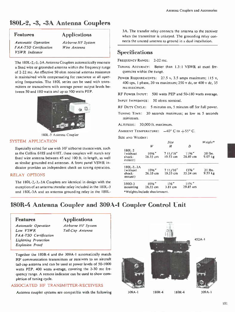
Antenna Couplers and Accessories
180L-2, -3, -34 Antenna Couplers
Features Applications
Automatic Operation
FAA-TSO Certification
VSWR Indicator
Airborne HF System
Wire Antenna
The 180L-2,-3,-3A Antenna Couplers automatically resonate
a fixed wire or grounded antenna within the frequency range
of 2-22 mc. An effective 50 ohm nominal antenna resistance
is maintained while compensating for reactance at all oper-
ating frequencies. The 180L series can be used with trans-
mitters or transceivers with average power output levels be-
tween 50 and 180 watts and up to 500 watts PEP.
180L-3 Antenna Coupler
SYSTEM APPLICATION
Especially suited for use with HF airborne transceivers, such
as the Collins 618S and 6I8T. these couplers will match any
fixed wire antenna between 45 and 100 ft. in length, as well
as similar grounded end antennas. A front panel VSWR in-
dicator provides an independent check on tuning operation.
RELAY OPTIONS
The 180L-2,-3,-3A Couplers are identical in design with the
exception of an antenna transfer relay included in the 180L-3
and 180L-3A and an antenna grounding relay in the 180L-
3A. The transfer relay connects the antenna to the receiver
when the transmitter is unkeyed. The grounding relay con-
nects the unused antenna to ground in a dual installation.
Specifications FREQUENCY RANGE: 2-22 mc.
TUNING ACCURACY: Better than 1.3:1 VSWR at most fre-
quencies within the range.
POWER REQUIREMENTS: 27.5 v, 3.5 amps maximum; 115 v,
400 cps, I phase, 20 va maximum; 250 y dc, or 400 y dc, 35
ma maximum.
RF POWER INPUT: 500 watts PEP and 50-180 watts average.
INPUT IMPEDANCE: 50 ohms nominal.
RF DUTY CYCLE: 5 minutes on, 5 minutes off for full power.
TUNING Time: 30 seconds maximum; as low as 5 seconds
minimum.
ALTITUDE: 30,000 ft. maximum.
AMBIENT TEMPERATURE: —40° C to +55° C.
SIZE AND W EIGHT: Size Weight* H D
180L-2 (without 103/4 " 7 11/16" 113i" 20 lbs. shock- 26.35 cm 19.53 cm 28.89 cm 9.07 kg mount)
180L-3,-3A (without 103/8" 7 11/16" 137/8" 21 lbs. shock- 26.35 cm 19.53 cm 35.24 cm 9.53 kg mount)
350D-3 103/4 " mounting 26.35 cm 3.81 cm 29.85 cm
*Weights include shockmount.
11/2 " 11 3/4 "
180R-4 Antenna Coupler and 309 A-1 Coupler Control Unit
Features Applications Automatic Operation
Low VSWR
FA A -TSO Certification
Lightning Protection
Explosion Proof
Airborne HF System
Tail-Cap Antenna
Together the 180R-4 and the 309A-1 automatically match
HF communication transmitters or receivers to an aircraft tail-cap antenna and can be used at power levels of 50-1000
watts PEP, 400 watts average, covering the 2-30 mc fre-
quency range. A remote indicator can be used to show com-
pletion of tuning cycle.
ASSOCIATED HF TRANSMITTER-RECEIVERS
Antenna coupler systems are compatible with the following
..T.J
309A-1 180R-4 180R-4 309A-1
452A-1
101
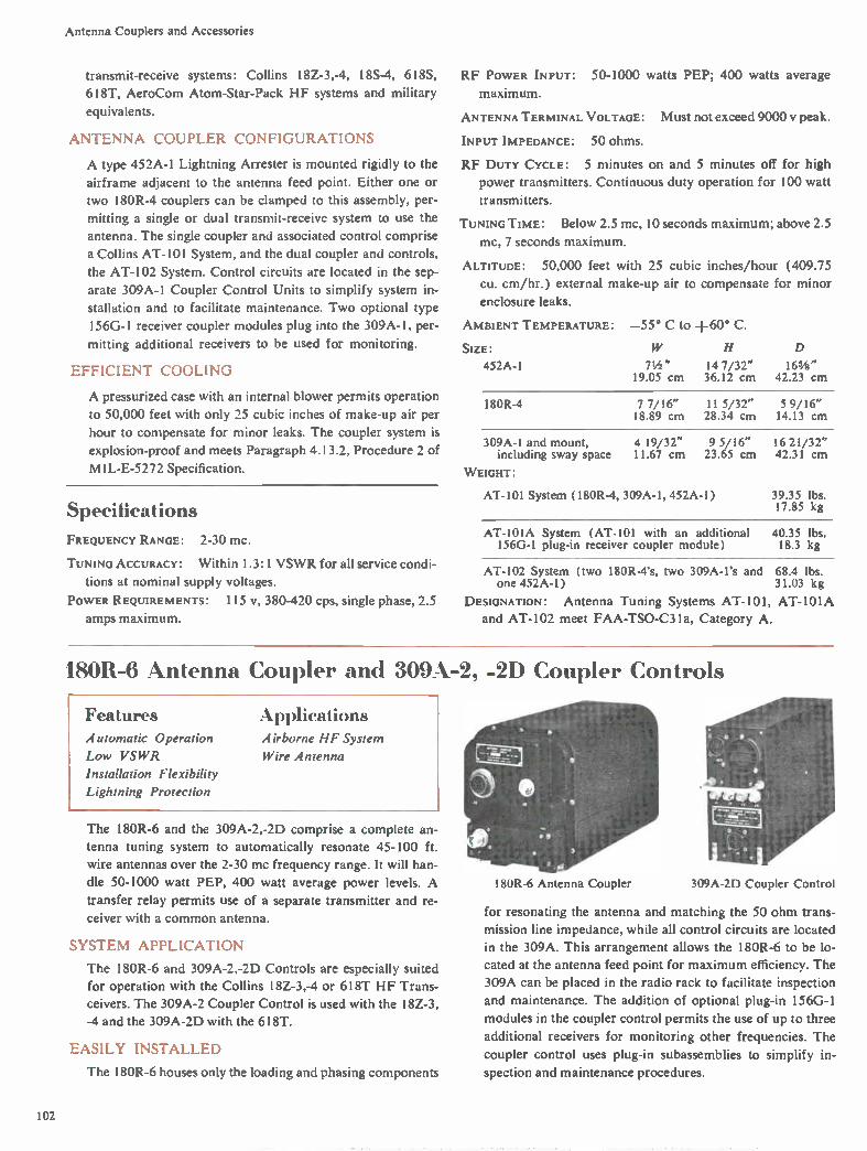
Antenna Couplers and Accessories
transmit-receive systems: Collins 18Z-3,-4, 18S-4, 618S,
618T, AeroCom Atom-Star-Pack HF systems and military
equivalents.
ANTENNA COUPLER CONFIGURATIONS
A type 452A-1 Lightning Arrester is mounted rigidly to the
airframe adjacent to the antenna feed point. Either one or
two 180R-4 couplers can be clamped to this assembly, per-
mitting a single or dual transmit-receive system to use the
antenna. The single coupler and associated control comprise
a Collins AT-101 System, and the dual coupler and controls,
the AT-l02 System. Control circuits are located in the sep-
arate 309A- 1 Coupler Control Units to simplify system in-
stallation and to facilitate maintenance. Two optional type
156G-I receiver coupler modules plug into the 309A-I, per-
mitting additional receivers to be used for monitoring.
EFFICIENT COOLING
A pressurized case with an internal blower permits operation
to 50,000 feet with only 25 cubic inches of make-up air per
hour to compensate for minor leaks. The coupler system is
explosion-proof and meets Paragraph 4.13.2, Procedure 2 of
MIL-E-5272 Specification.
Specifications
FREQUENCY RANGE: 2-30 mc.
TUNING ACCURACY: Within 1.3:1 VSWR for all service condi-
tions at nominal supply voltages.
POWER REQUIREMENTS: 115 N.', 380-420 cps, single phase, 2.5
amps maximum.
RF POWER INPUT: 50-1000 watts PEP; 400 watts average
maximum.
ANTENNA TERMINAL VOLTAGE: Must not exceed 9000 v peak.
INPUT IMPEDANCE: 50 ohms.
RF DUTY CYCLE: 5 minutes on and 5 minutes off for high
power transmitters. Continuous duty operation for 100 watt
transmitters.
TUNING TIME: Below 2.5 mc, 10 seconds maximum; above 2.5
mc, 7 seconds maximum.
ALTITUDE: 50,000 feet with 25 cubic inches/hour (409.75
Cu. cm/hr.) external make-up air to compensate for minor
enclosure leaks.
AMBIENT TEMPERATURE: —55° C to +60° C.
SIZE: 452A-1
H D
71/2 " 14 7/32" 165/8" 19.05 cm 36.12 cm 42.23 cm
180R-4 7 7/16" 11 5/32" 5 9/16" 18.89 cm 28.34 cm 14.13 cm
309A-1 and mount, 4 19/32" 9 5/16" 16 21/32" including sway space 11.67 cm 23.65 cm 42.31 cm
WEIGHT:
AT-101 System (180R-4, 309A-1, 452A-1) 39.35 lbs. 17.85 kg
AT-101A System (AT-101 with an additional 40.35 lbs. 156G-1 plug-in receiver coupler module) 18.3 kg
AT-102 System (two 180R-4's, two 309A-1's and 68.4 lbs. one 452A-1) 31.03 kg
DESIGNATION: Antenna Tuning Systems AT-101, AT-101A
and AT-102 meet FAA-TSO-C31a, Category A.
180R-6 Antenna Coupler and 309A-2, -2D Coupler Controls
Features Automatic Operation
Low VSWR
Installation Flexibility
Lightning Protection
Applications Airborne HF System
Wire Antenna
The 180R-6 and the 309A-2,-2D comprise a complete an-
tenna tuning system to automatically resonate 45-100 ft.
wire antennas over the 2-30 mc frequency range. It will han-
dle 50-1000 watt PEP, 400 watt average power levels. A
transfer relay permits use of a separate transmitter and re-
ceiver with a common antenna.
SYSTEM APPLICATION
The 180R-6 and 309A-2,-2D Controls are especially suited
for operation with the Collins I 8Z-3,-4 or 6I8T HF Trans-
ceivers. The 309A-2 Coupler Control is used with the I8Z-3,
-4 and the 309A-2D with the 618T.
EASILY INSTALLED
The 180R-6 houses only the loading and phasing components
180R-6 Antenna Coupler 309A-2D Coupler Control
for resonating the antenna and matching the 50 ohm trans-
mission line impedance, while all control circuits are located
in the 309A. This arrangement allows the 180R-6 to be lo-
cated at the antenna feed point for maximum efficiency. The
309A can be placed in the radio rack to facilitate inspection
and maintenance. The addition of optional plug-in 156G-1
modules in the coupler control permits the use of up to three
additional receivers for monitoring other frequencies. The
coupler control uses plug-in subassemblies to simplify in-
spection and maintenance procedures.
102

Antenna Couplers and Accessories
Specifications FREQUENCY RANGE: 2-30 mc.
TUNING ACCURACY: Within 1.3:1 VSWR for all service con-
ditions at nominal supply voltages.
POWER REQUIREMENTS: 115 V, 380-420 cps, 2 amps, maximum.
RF POWER INPUT: 50-1000 watts PEP; 400 watts average
maximum.
INPUT IMPEDANCE: 50 ohms nominal.
RF DUTY CYCLE: Continuous for SSB and AM; 5 minutes on,
5 minutes off, maximum for continuous 400 watt single tone.
TUNING TIME: 30 seconds maximum.
ALTITUDE: 20,000 ft. maximum, nonpressurized model. A
pressurized model, 180R-7, may be operated to 75,000 ft.
AMBIENT TEMPERATURE: —55° C to +71° C, operating;
—65° C to +85° C, storage.
SIZE AND WEIGHT:
180R-6 7"
17.78 cm
Size H 91/2 -
24.13 cm
D
17 7/32" 43.74 cm
Weight
21.5 lbs. 9.75 kg
180R-6 with lightning 7" 91/2 " 29 19/32" 24.5 lbs. arrestor 17.78 cm 24.13 cm 75.17 cm 11.1 kg
309A-2,-2D 3 11/16" 75/8" 141/2 " 12.4 lbs. 9.37 cm 19.37 cm 36.83 cm 5.62 kg
309A-2,-2D with three optional 156G-1 receiver couplers
14 lbs. 6.35 kg
180R-6A Line Flattener and 309A-2E Control
Features Automatic Operation
Fifty Ohm Coaxial Lines
Low VSWR
Easily Installed
AppliCaliOrIS
Fixed Station
Transportable
Shipboard
309A-2E Control 180R-6A Line Flattener
The 180R-6A and 309A-2E comprise an efficient system to
automatically match the 50 ohm output of a power amplifier,
transmitter or transceiver to an antenna feed line over the
2-30 mc frequency range. It will maintain a 1.3:1 VSWR
from terminations with up to 3:1 VSWR at power levels of
up to I kw PEP, 400 watts average.
SYSTEM APPLICATION
Designed specifically for use with SSB power amplifiers, such
as the Collins 548L-4, it is ideally suited for fixed station,
transportable or shipboard installations. The loading and
phasing components are housed in the 180R-6A, while the
control circuits are housed in the 309A-2E. Plug-in subas-
semblies in the 309A-2E simplify maintenance.
Specifications FREQUENCY RANGE: 2-30 mc.
VSWR: 1.3:1 VSWR or less.
ANTENNA: 3:1 VSWR maximum.
POWER REQUIREMENTS: 115 v, 380-420 cps, and 27.5 y dc,
2 amps.
RF POWER INPUT: 50-1000 watts PEP; 400 watts average
maximum.
INPUT IMPEDANCE: 50 ohms nominal.
RF DUTY CYCLE: Continuous for SSB and AM; 5 minutes on,
5 minutes off, maximum for RTTY ( 1000 watts average
power).
TUNING TIME: 30 seconds maximum.
ALTITUDE: 20,000 ft. maximum.
SIZE AND WEIGHT:
Size H
180R-6A 7" 17.78 cm
91/2 -24.13 cm
D
17 7/32" 43.74 cm
Weight
19.5 lbs. 8.85 kg
309A-2E 3 11/16" 75/8" 141/2 11.75 lbs. 9.37 cm 19.37 cm 36.83 cm 5.33 kg
180R-12 Antenna Coupler and 309A-9 Coupler Control Unit
Features Automatic Operation
FAA-TS° Certification
Protective Circuitry
Applications Boeing 727 Aircraft
Boeing 707 Aircraft
Boeing KC-I35 Aircraft
The 180R-12, together with the 309A-9, automatically
matches the RF impedance of communication equipment
operating in the 2-30 mc frequency range to an aircraft
probe-type antenna. The system is automatically tuned in 16
seconds maximum. Typical tuning time is five seconds.
AIRCRAFT APPLICATIONS
The 180R-I2 Antenna Coupler, designed for the Boeing 727,
can be retrofitted for the 707 or KC-135 aircraft by the addi-
tion of airframe cabling and moving a tap on an RF coil. It
103
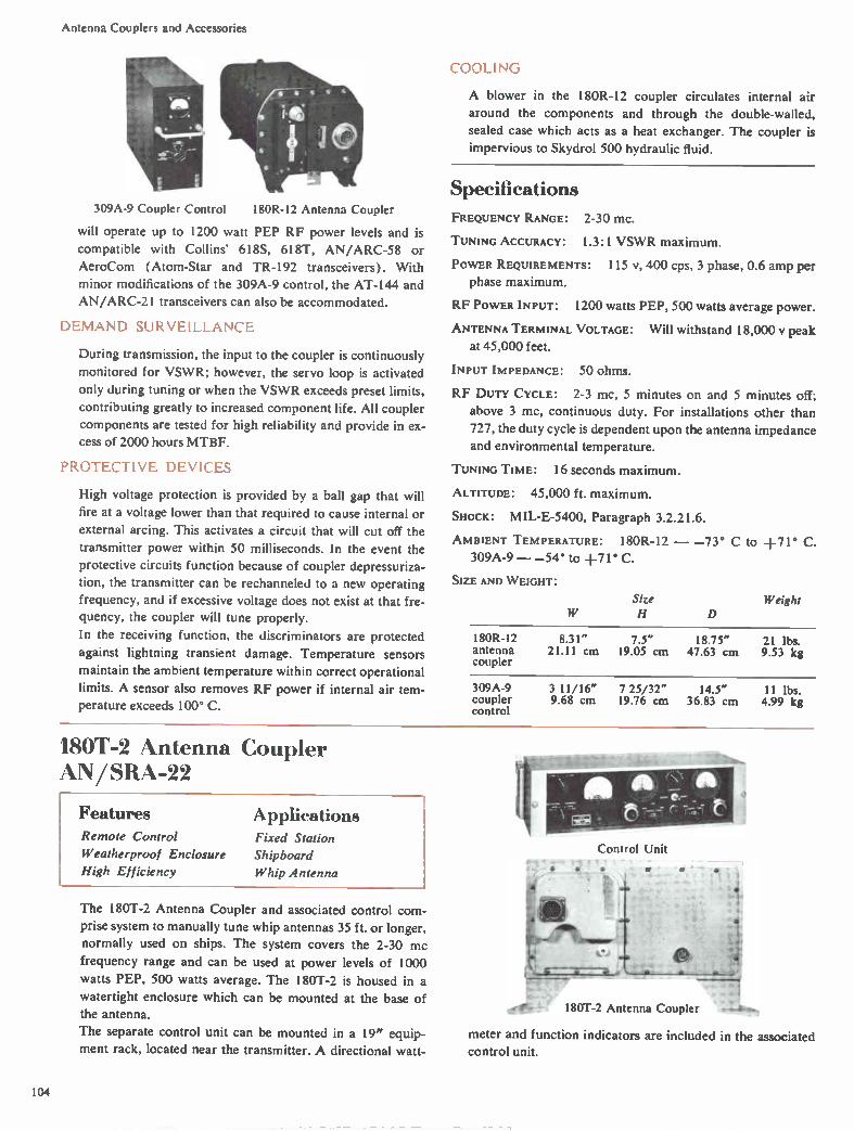
Antenna Couplers and Accessories
309A-9 Coupler Control 180R-I2 Antenna Coupler
will operate up to 1200 watt PEP RF power levels and is
compatible with Collins' 618S, 618T, AN/ARC-58 or
AeroCom (Atom-Star and TR-192 transceivers). With
minor modifications of the 309A-9 control, the AT-144 and
AN/ARC-2I transceivers can also be accommodated.
DEMAND SURVEILLANCE
During transmission, the input to the coupler is continuously
monitored for VSWR; however, the servo loop is activated
only during tuning or when the VSWR exceeds preset limits,
contributing greatly to increased component life. All coupler
components are tested for high reliability and provide in ex-
cess of 2000 hours MTBF.
PROTECTIVE DEVICES
High voltage protection is provided by a ball gap that will
fire at a voltage lower than that required to cause internal or
external arcing. This activates a circuit that will cut off the
transmitter power within 50 milliseconds. In the event the
protective circuits function because of coupler depressuriza-
tion, the transmitter can be rechanneled to a new operating
frequency, and if excessive voltage does not exist at that fre-
quency, the coupler will tune properly.
In the receiving function, the discriminators are protected
against lightning transient damage. Temperature sensors
maintain the ambient temperature within correct operational
limits. A sensor also removes RF power if internal air tem-
perature exceeds 100° C.
COOLING
A blower in the 180R-12 coupler circulates internal air
around the components and through the double-walled,
sealed case which acts as a heat exchanger. The coupler is
impervious to Skydrol 500 hydraulic fluid.
Specifications
FREQUENCY RANGE:
TUNING ACCURACY:
2-30 mc.
1.3:1 VSWR maximum.
POWER REQUIREMENTS: 115 1/, 400 cps, 3 phase, 0.6 amp per
phase maximum.
RF POWER INPUT: 1200 watts PEP, 500 watts average power.
ANTENNA TERMINAL VOLTAGE:
at 45,000 feet. Will withstand 18,000 y peak
INPUT IMPEDANCE: 50 ohms.
RF DUTY CYCLE: 2-3 mc, 5 minutes on and 5 minutes off;
above 3 mc, continuous duty. For installations other than
727, the duty cycle is dependent upon the antenna impedance and environmental temperature.
TUNING TIME: 16 seconds maximum.
ALTITUDE: 45,000 ft. maximum.
SHOCK: MIL-E-5400, Paragraph 3.2.21.6.
AMBIENT TEMPERATURE: 180R-12 — —73° C to +71° C.
309A-9 — —54° to +71° C.
SIZE AND WEIGHT:
Size H D
Weight
180R-12 8.31" 7.5" 18.75" 21 lbs. antenna 21.11 cm 19.05 cm 47.63 cm 9.53 kg coupler
309A-9 3 11/16" 7 25/32" 14.5" 11 lbs. coupler 9.68 cm 19.76 cm 36.83 cm 4.99 kg control
180T-2 Antenna Coupler AN/SRA-22
Features Remote Control
Weatherproof Enclosure
High Efficiency
Applications Fixed Station
Shipboard
Whip Antenna
The 180T-2 Antenna Coupler and associated control com-
prise system to manually tune whip antennas 35 ft. or longer,
normally used on ships. The system covers the 2-30 mc
frequency range and can be used at power levels of 1000
watts PEP, 500 watts average. The 180T-2 is housed in a
watertight enclosure which can be mounted at the base of
the antenna.
The separate control unit can be mounted in a 19" equip-
ment rack, located near the transmitter. A directional watt-
Control Unit
- 180T-2 Antenna Coupler
meter and function indicators are included in the associated control unit.
104
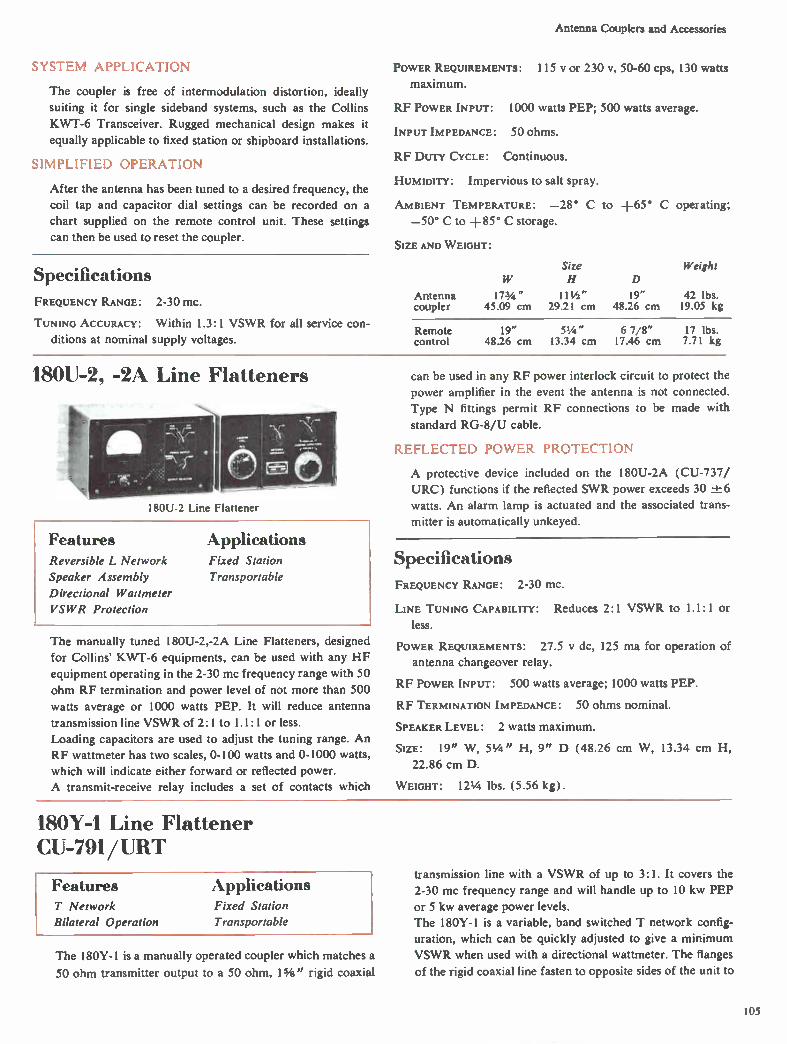
Antenna Couplers and Accessories
SYSTEM APPLICATION
The coupler is free of intermodulation distortion, ideally
suiting it for single sideband systems, such as the Collins
KWT-6 Transceiver. Rugged mechanical design makes it
equally applicable to fixed station or shipboard installations.
SIMPLIFIED OPERATION
After the antenna has been tuned to a desired frequency, the
coil tap and capacitor dial settings can be recorded on a
chart supplied on the remote control unit. These settings
can then be used to reset the coupler.
Specifications FREQUENCY RANGE: 2-30 mc.
TUNING ACCURACY: Within 1.3:1 VSWR for all service con-
ditions at nominal supply voltages.
POWER REQUIREMENTS: 115 y or 230 v, 50-60 cps, 130 watts
maximum.
RF POWER INPUT: 1000 watts PEP; 500 watts average.
INPUT IMPEDANCE: 50 ohms.
RF DUTY CYCLE: Continuous.
HUMIDITY: Impervious to salt spray.
AMBIENT TEMPERATURE: —28° C to +65° C operating;
—50° C to +85° C storage.
SIZE AND WEIGHT:
Antenna coupler
173/4 " 45.09 cm
Size H
11 1/2 " 29.21 cm
D
19" 48.26 cm
Weight
42 lbs. 19.05 kg
Remote 19" 51/4 - 6 7/8" 17 lbs. control 48.26 cm 13.34 cm 17.46 cm 7.71 kg
180U-2, -2A Line Flatteners
180U-2 Line Flattener
Features Reversible L Network
Speaker Assembly
Directional Wattmeter
VSWR Protection
Applications Fixed Station
Transportable
The manually tuned 180U-2,-2A Line Flatteners, designed
for Collins' KWT-6 equipments, can be used with any HF
equipment operating in the 2-30 mc frequency range with 50
ohm RF termination and power level of not more than 500
watts average or 1000 watts PEP. It will reduce antenna
transmission line VSWR of 2: 1 to 1.1:1 or less.
Loading capacitors are used to adjust the tuning range. An
RF wattmeter has two scales, 0-100 watts and 0-1000 watts,
which will indicate either forward or reflected power.
A transmit-receive relay includes a set of contacts which
can be used in any RF power interlock circuit to protect the
power amplifier in the event the antenna is not connected.
Type N fittings permit RF connections to be made with
standard RG-8/U cable.
REFLECTED POWER PROTECTION
A protective device included on the 180U-2A (CU-737/
URC) functions if the reflected SWR power exceeds 30 ±6
watts. An alarm lamp is actuated and the associated trans-
mitter is automatically unkeyed.
Specifications FREQUENCY RANGE: 2-30 mc.
LINE TUNING CAPABILITY: Reduces 2:1 VSWR to 1.1:1 or
less.
POWER REQUIREMENTS: 27.5 y dc, 125 ma for operation of
antenna changeover relay.
RF POWER INPUT: 500 watts average; 1000 watts PEP.
RF TERMINATION IMPEDANCE: 50 ohms nominal.
SPEAKER LEVEL: 2 watts maximum.
SIZE: 19" W, 51/4 " H, 9" D (48.26 cm W, 13.34 cm H,
22.86 cm D.
WEIGHT: 121/4 lbs. (5.56 kg).
180Y-1 Line Flattener CU-791/ URT
Features T Network
Bilateral Operation
Applications Fixed Station
Transportable
The 180Y-1 is a manually operated coupler which matches a
50 ohm transmitter output to a 50 ohm, 11/4 " rigid coaxial
transmission line with a VSWR of up to 3:1. It covers the
2-30 mc frequency range and will handle up to 10 kw PEP
or 5 kw average power levels.
The 180Y-1 is a variable, band switched T network config-
uration, which can be quickly adjusted to give a minimum
VSWR when used with a directional wattmeter. The flanges
of the rigid coaxial line fasten to opposite sides of the unit to
105

Antenna Couplers and Accessories
180Y-I Line Flattener
permit equipment removal without disturbing the coaxial
transmission line.
The coupler is bilateral, allowing either connector to be used
as the input or output except for resistances below 25 ohms
in the 2.0-2.6 mc frequency band. All controls, together with
a tuning chart, are located on the front panel.
Specifications
FREQUENCY RANGE: 2-30 !TIC.
LINE TUNING CAPABILITY: 3:1 VSWR maximum.
POWER REQUIREMENTS: None.
RF POWER INPUT: Operate — 10 kw PEP; 5 kw average
maximum. Tune — 1 kw average maximum.
INPUT IMPEDANCE: 50 ohms.
OUTPUT IMPEDANCE: 50 ohms.
RF DUTY CYCLE: Continuous.
AMBIENT TEMPERATURE: —20° C to +50° C.
AMBIENT HUMIDITY: 0%-95%.
SIZE: 7" W , 11 5/8" H, 16 11/16" D (17.78 cm W, 29.53 cm
H, 42.39 cm D).
W EIGHT: 23 1/2 lbs. (10.66 kg).
184U-10 RF Matrix t nism itch
Features Building Block Flexibility
Improved RF Switching
Mechanical Interlocks
Small Size
Simplified Maintenance
Remotely Controlled
Applications Antenna Transmitter
Matrix
Fixed Station
Shipboard
Uniswitch Building Block
The 184U-10 is a single, coaxial crosspoint-switch for build-
ing block assembly of an RF matrix to switch any of several
transmitters to any of several antennas. The matrix permits
either local or remote selection and can be assembled to ex-
actly meet individual requirements. Mechanical and electri-
cal interlocks prevent paralleling or application of power to
an open line.
UNISWITCH OPERATION
The 184U-10 Uniswitch employs a simple, single stroke ac-
tuating mechanism which moves a dual contact assembly to
disconnect both potential RF stubs as the desired crosspoint
is established. Long life is assured by the simplicity of the
mechanism and controlled contact acceleration.
Typical 3 x 5 RF Matrix
MATRIX ASSEMBLY
Several Uniswitches — one for each crosspoint — are sim-
ply bolted on easily constructed Unistrut frame sections to
form the desired matrix configuration. The matrix can be
modified by adding Uniswitches and frame sections if com-
munication requirements change. Small size permits wall
mountings in any position.
SIMPLIFIED MAINTENANCE
Individual Uniswitches can be removed for inspection or
maintenance without disturbing other crosspoints. RF lines
can be grounded during servicing. Control circuitry is easily
accessible while crosspoint is in operation by removal of
front cover.
LOW POWER OPERATION
Control wiring is simplified by the low total power require-
ment of approximately 10 watts, including status display
lights and all control relays.
REMOTE CONTROL
Since RF switching is accomplished by a single relay in each
106

Antenna Couplers and Accessories
Uniswitch, wide flexibility in remote control application is
possible.
Lighted display pushbuttons, with red and green status
lamps, can be conveniently used for remote switching. The
red lamp indicates when crosspoint is switching and the
green lamp when it is closed. Depressing the button a second
time opens the crosspoint and both lamps go out.
Open
jjgr,1
Jr
Closed
Specifications RF COAXIAL LINE: 50 ohm EIA, 15/8", rigid coax.
POWER RATING: 45 kw average with a 1: 1 VSWR at 30 mc.
CURRENT RATING: 30 amps rms, 2-30 mc.
VOLTAGE RATING: 2000 y rms, 2-30 mc.
FREQUENCY RANGE: 30 mc maximum.
VSWR: When matrix is terminated in 50 ohm resistive load,
the VSWR presented at the input shall not exceed 1.05:1
at 30 mc.
CROSS-TALK: —65 db.
OPERATION: Manual or remote control.
OPERATE TIME: 0.5 second.
REMOTE CONTROL: Single wire ground; other options.
CONTROL POWER: 27.5 y dc at 0.25 amp when switching.
STATUS DISPLAY: SPST.
MANUAL OVERRIDE: Manual operation possible in case of
control failure.
RF FITTINGS: Adapters for all common fittings.
SIZE: 5½" W, 51/2 " H, 18" D (13.97 cm W, 13.97 cm H,
45.72 cm D).
WEIGHT: Manual — 41/2 lbs. (2.04 kg). Remote — 61/2 lbs.
2.95 kg).
488A-I DC to AC Inverter
Features Continuous Duty
No Shockmount
Transient Protection
Lightweight
Applications Airborne
Fixed Station
Transportable
Mobile
The 488A-1 is a dc to 115 v, 400 cps or 26 v, 400 cps inverter.
It facilitates use of equipment requiring a small amount of
400 cps power in applications where only 27.5 y dc is avail-
able. Output is 250 va at +55° C, with a frequency accuracy
of -± 5 % and an output regulation of zE_-_10%. Transient pro-
tection is provided for up to 65 y peaks. Since the 488A-1
can be mounted directly to the aircraft or vehicle, installation
is simplified.
Specifications
POWER SOURCE: 27.5 y dc, 4-25 amps, depending on load.
Unit will withstand 65 y transients on supply line.
OUTPUT: Continuous —250 va, 115 v ac, 400 cps at not more
than 55° C; or 170 va, 115 y ac, 400 cps at 55°-70° C; or
140 va, 26 v ac, 400 cps at not more than 55° C. Output volt-
age regulated to within -± 10%. Output frequency within
J.= 5 % . Distortion is less than 10%. Efficiency is 60%.
DUTY CYCLE: Continuous.
AMBIENT TEMPERATURE: —40° C to +70° C.
AMBIENT HUMIDITY: Up to 95% at 50° C.
ALTITUDE: • Up to 10,000 ft. at 70° C; higher altitudes at re-
duced temperatures or loads.
SHOCK CONDITIONS: Per RTCA paper 100-54/D0-60, except
where angles are called out as 45°, use 90°.
VIBRATIONS: Per RTCA paper 100-54/D0-60.
SIZE: 63/4 " W, 5¼" H, 93/4 " D (17.15 cm W, 14.29 cm H,
24.77 cm D).
WEIGHT: 9.25 lbs. (4.2 kg).
107
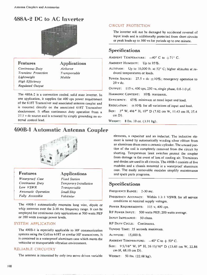
Antenna Couplers and Accessories
488A-2 DC to AC Inverter
Features Continuous Duty
Transient Protection
Lightweight
High Efficiency
Regulated Output
Applications Airborne
Transportable
Mobile
The 488A-2 is a convection cooled, solid state inverter. In
one application, it supplies the 400 cps power requirement
of the 618T Transceiver and associated antenna coupler and
is mounted directly on the associated 618T Transceiver
shockmount. It offers continuous duty operation from a
27.5 y dc source and is actuated by simply grounding an ex-ternal control lead.
CIRCUIT PROTECTION
The inverter will not be damaged by accidental reversal of
input leads and is additionally protected from short circuits
or peak loads up to 300 va for periods up to one minute.
Specifications
AMBIENT TEMPERATURE: —40° C to +71° C.
AMBIENT HUMIDITY: Up IO 95%.
ALTITUDE: Up to 10,000 ft. at 52° C; higher altitudes at re-
duced temperatures or loads.
POWER SOURCE: 27.5 y dc 10%; emergency operation to 20 y dc.
OUTPUT: 115 v, 400 cps, 250 va, single phase, 0.8-1.0 pf.
HARMONIC CONTENT: 10% maximum.
EFFICIENCY: 65% minimum at rated input and load.
REGULATION: +10% for all variations of input and load.
SIZE: 3" W, 4½" H, 10" D (7.62 cm W, 11.43 cm H, 25.4
cm D).
W EIGHT: 8 lbs. 10 oz. (3.91 kg).
490B-I Automatic Antenna Coupler
*... •
e tit e
Features Waterproof Case
Continuous Duty
Low VSWR
Automatic Operation
Fully Accessible
Applications Fixed Station
Temporary Installation
Transportable
Small Ship
Vehicular
The 490B-1 automatically resonates long wire, dipole or whip antennas over the 2-30 mc frequency range. It can be
employed for continuous duty applications at 500 watts PEP or 200 watts average power levels.
SYSTEM APPLICATION
The 490B-1 is especially applicable to HF communication
systems using the Collins 618T or similar HF transceivers. It
is contained in a waterproof aluminum case which meets the vehicular or transportable vibration environment.
RELIABLE CIRCUITRY
The antenna is resonated by only two servo driven variable
elements, a capacitor and an inductor. The inductive ele-
ment is tuned by automatically winding silver ribbon from
an aluminum drum onto a ceramic cylinder. The unused por-
tion of the coil is completely removed from the circuit by
shorting. Temperature limit switches protect the coupler
from damage in the event of loss of cooling air. Transistors and diodes are used in all circuits. The 490B-1 consists of five
modules and a chassis mounted in a waterproof aluminum
case. The easily removable modules simplify maintenance and spare parts programs.
Specifications
FREQUENCY RANGE: 2-30 MC.
FREQUENCY ACCURACY: Within 1.3:1 VSWR for all service
conditions at nominal supply voltages.
POWER REQUIREMENTS: 115 v, 400 cps.
RF POWER INPUT: 500 watts PEP; 200 watts average.
INPUT IMPEDANCE: 50 ohms.
RF DUTY CYCLE: Continuous.
TUNING TIME: 35 seconds maximum.
ALTITUDE: 15,000 ft.
AMBIENT TEMPERATURE: —40° C to + 50° C.
SIZE: 9 5/16" W, 9" H, 26 13/16" D (23.65 cm W, 22.86 cm H, 68.10 cm D).
W EIGHT: 50 lbs. (22.68 kg).
108
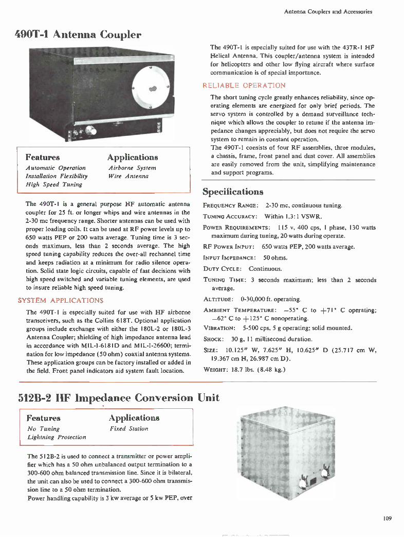
Antenna Couplers and Accessories
490T-1 Antenna Coupler
Applications Features Automatic Operation
Installation Flexibility
High Speed Tuning
Airborne System
Wire Antenna
The 490T-1 is a general purpose HF automatic antenna
coupler for 25 ft. or longer whips and wire antennas in the
2-30 mc frequency range. Shorter antennas can be used with
proper loading coils. It can be used at RF power levels up to
650 watts PEP or 200 watts average. Tuning time is 3 sec-
onds maximum, less than 2 seconds average. The high
speed tuning capability reduces the over-all rechannel time
and keeps radiation at a minimum for radio silence opera-
tion. Solid state logic circuits, capable of fast decisions with
high speed switched and variable tuning elements, are used
to insure reliable high speed tuning.
SYSTEM APPLICATIONS
The 490T-1 is especially suited for use with HF airborne
transceivers, such as the Collins 618T. Optional application
groups include exchange with either the 180L-2 or 180L-3
Antenna Coupler; shielding of high impedance antenna lead
in accordance with M1L-I-6181D and MIL-I-26600; termi-
nation for low impedance (50 ohm) coaxial antenna systems.
These application groups can be factory installed or added in
the field. Front panel indicators aid system fault location.
The 490T-1 is especially suited for use with the 437R-1 HF
Helical Antenna. This coupler/antenna system is intended
for helicopters and other low flying aircraft where surface
communication is of special importance.
RELIABLE OPERATION
The short tuning cycle greatly enhances reliability, since op-
erating elements are energized for only brief periods. The
servo system is controlled by a demand surveillance tech-
nique which allows the coupler to retune if the antenna im-
pedance changes appreciably, but does not require the servo
system to remain in constant operation.
The 490T-1 consists of four RF assemblies, three modules,
a chassis, frame, front panel and dust cover. All assemblies
are easily removed from the unit, simplifying maintenance
and support programs.
Specifications FREQUENCY RANGE: 2-30 mc, continuous tuning.
TUNING ACCURACY: Within 1.3:1 VSWR.
POWER REQUIREMENTS: 115 v, 400 cps, I phase, 130 watts
maximum during tuning, 20 watts during operate.
RF POWER INPUT: 650 watts PEP, 200 watts average.
INPUT IMPEDANCE: 50 ohms.
DUTY CYCLE: Continuous.
TUNING TIME: 3 seconds maximum; less than 2 seconds
average.
ALTITUDE: 0-30,000 ft. operating.
AMBIENT TEMPERATURE: —55° C to +71° C operating;
—62° C to +125° C nonoperating.
VIBRATION: 5-500 cps, 5 g operating; solid mounted.
SHOCK: 30 g, 11 millisecond duration.
SIZE: 10.125" W, 7.625" H, 10.625" D (25.717 cm
19.367 cm H, 26.987 cm D).
WEIGHT: 18.7 lbs. (8.48 kg.)
W,
512B-2 HF Impedance Conversion Unit
Features Applications No Tuning Fixed Station
Lightning Protection
The 512B-2 is used to connect a transmitter or power ampli-
fier which has a 50 ohm unbalanced output termination to a
300-600 ohm balanced transmission line. Since it is bilateral,
the unit can also be used to connect a 300-600 ohm transmis-
sion line to a 50 ohm termination.
Power handling capability is 3 kw average or 5 kw PEP, over
109
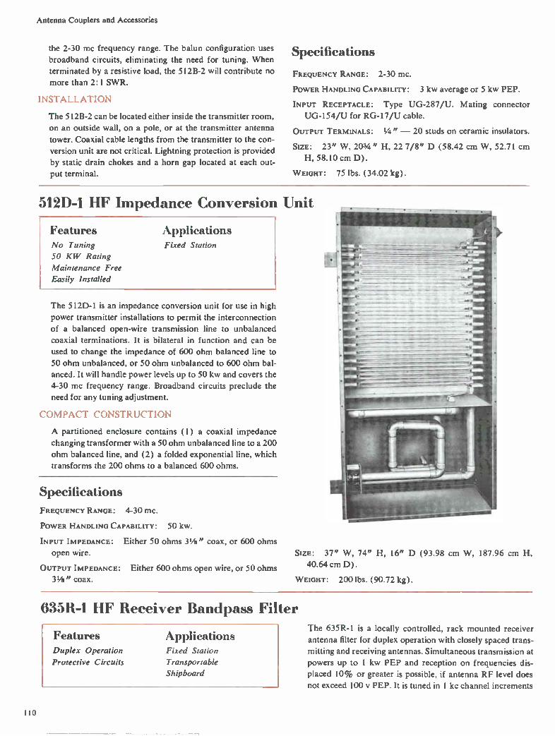
Antenna Couplers and Accessories
the 2-30 mc frequency range. The balun configuration uses
broadband circuits, eliminating the need for tuning. When
terminated by a resistive load, the 512B-2 will contribute no
more than 2:1 SWR.
INSTALLATION
The 512B-2 can be located either inside the transmitter room,
on an outside wall, on a pole, or at the transmitter antenna
tower. Coaxial cable lengths from the transmitter to the con-
version unit are not critical. Lightning protection is provided
by static drain chokes and a horn gap located at each out-
put terminal.
Specifications
FREQUENCY RANGE: 2-30 mc.
POWER HANDLING CAPABILITY: 3 kw average or 5 kw PEP.
INPUT RECEPTACLE: Type UG-287/U. Mating connector
UG-154/U for RG-17/U cable.
OUTPUT TERMINALS: " — 20 studs on ceramic insulators.
SIZE: 23" W, 203/4 " H, 22 7/8" D (58.42 cm W, 52.71 cm
H, 58.10 cm D).
W EIGHT: 75 lbs. (34.02 kg).
512D-1 HF Impedance Conversion Unit
Features No Tuning
50 KW Rating
Maintenance Free
Easily Installed
Applications Fixed Station
The 512D-1 is an impedance conversion unit for use in high
power transmitter installations to permit the interconnection
of a balanced open-wire transmission line to unbalanced
coaxial terminations. It is bilateral in function and can be
used to change the impedance of 600 ohm balanced line to
50 ohm unbalanced, or 50 ohm unbalanced to 600 ohm bal-
anced. It will handle power levels up to 50 kw and covers the
4-30 mc frequency range. Broadband circuits preclude the
need for any tuning adjustment.
COMPACT CONSTRUCTION
A partitioned enclosure contains (1) a coaxial impedance
changing transformer with a 50 ohm unbalanced line to a 200
ohm balanced line, and (2) a folded exponential line, which
transforms the 200 ohms to a balanced 600 ohms.
Specifications
FREQUENCY RANGE: 4-30 mc.
POWER HANDLING CAPABILITY: 50 kw.
INPUT IMPEDANCE: Either 50 ohms 31/ii" coax, or 600 ohms
open wire.
OUTPUT IMPEDANCE: Either 600 ohms open wire, or 50 ohms
31/a" coax.
SIZE: 37" W, 74" H, 16" D (93.98 cm W, 187.96 cm H,
40.64 cm D).
W EIGHT: 200 lbs. (90.72 kg).
635R-1 HF Receiver Bandpass Filter
Features Duplex Operation
Protective Circuits
Applications Fixed Station
Transportable
Shipboard
The 635R-1 is a locally controlled, rack mounted receiver
antenna filter for duplex operation with closely spaced trans-
mitting and receiving antennas. Simultaneous transmission at
powers up to 1 kw PEP and reception on frequencies dis-
placed 10% or greater is possible, if antenna RF level does
not exceed 100 y PEP. It is tuned in 1 kc channel increments
110

Antenna Couplers and Accessories
4•1•2 e tiFeli.sPerVeli....—
•§.t.•§2•::•::•::•::.§..:§;::::•::•:t:§ •
***
635R-I
throughout the 2.0-29.999 mc frequency range. The 635R-1
has a self-contained power supply for operation from a 115 v
or 230 v, 50-60 cps source.
RECEIVER PROTECTION
A protection circuit automatically disconnects the 635R-1
from the antenna if RF levels exceed 100 y peak. Tune inter-
lock circuits allow it to be controlled in common with the
associated receiver by any control unit using a two-out-of-
five frequency information code.
Specifications
FREQUENCY RANGE: 2.0-29.999 mc; 1 kc channel increments.
TYPES OF SIGNALS: AM, SSB and CW.
INPUT IMPEDANCE: 50 ohms unbalanced.
OUTPUT IMPEDANCE: 50 ohms unbalanced.
SELECTIVITY: The gain shall not deviate more than 1 db from
the gain at the dial frequency for all frequencies which are
within ±0.3% of dial frequency for the 2.0 mc through
14.999 mc range and within ±45 kc of dial frequency for the
15.0 mc through 29.999 mc range. The attenuation at
-± 10% of the dial frequency shall be not less than 70 db be-
low the referenced dial frequency gain from 2-8 mc, not less
than 65 db from 8-12 mc, not less than 60 db from 12-20 mc,
and not less than 50 db from 20.0-29.999 mc.
VOLTAGE GAIN: Not greater than 5.0 db or less than 0.5 db
at center frequency.
INTERMODULATION: All harmonic and intermodulation dis-
tortion at least 50 db below a 10 millivolt PEV output.
CROSS-MODULATION: At least 10 db below a desired 2 milli-
volt CW signal when receiving an undesired 91 y peak signal
(modulated 30% at 400 cps) at least ± 10% displaced from
the desired frequency.
POWER REQUIREMENTS: 115 y or 230 v, 50-60 cps, 30 watts
maximum.
SIZE: 19" W, 83/4 " H, 7" D (48.26 cm W, 22.23 cm H, 17.78
cm D). Mounts in 19" rack.
WEIGHT: 25 lbs. ( 11.34 kg).
635T-2 HF Receiver Bandpass Filter
Features Applications Automatic Tuning Fixed Station
Unattended Operation Transportable
Protective Circuits Shipboard
Airborne
The automatically tuned 635T-2 functions as a frequency se-
lecting circuit between the antenna and receiver input. It is
remotely tuned in I kc channel increments throughout the
2.0-29.999 mc frequency range by an associated 914B-2
Control Unit. The 635T-2 permits duplex operation where
transmitting and receiving antennas are closely spaced with
frequencies displaced 10% or greater if antenna RF level does not exceed 100 y PEP. Transmitter power can be up to
1 kw PEP. The 635T-2 has a self-contained power supply
for operation from a 22-30 y dc source. It is housed in a
standard 1/2 ATR case.
RECEIVER PROTECTION
RF levels exceeding 100 y peak are eliminated by a protec-
tion circuit that automatically disconnects the 635T-2 from
the antenna. Tune interlock circuits allow it to be controlled
in common with the associated receiver by any control unit
using a two-out-of-five frequency information code.
914B-2 Control Unit
Specifications FREQUENCY RANGE: 2.0-29.999 mc; 1 kc channel increments.
FREQUENCY CONTROL: By remote selection on the 914B-2
Control Unit.
TYPES OF SIGNALS: AM, SSB and CW.
INPUT IMPEDANCE: 50 ohms unbalanced.
OUTPUT IMPEDANCE: 50 ohms unbalanced.
SELECTIVITY: The gain shall not deviate more than I db from
the gain at the dial frequency for all frequencies which are
within ±-0.3% of dial frequency for the 2.0-14.999 mc range
and ±45 kc of dial frequency for the 15.0-29.999 mc range.
The attenuation at -± 10% of the dial frequency shall be not
less than 70 db below the referenced dial frequency gain from
II I
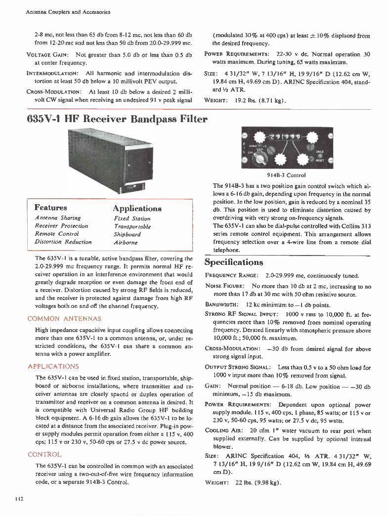
Antenna Couplers and Accessories
2-8 mc, not less than 65 db from 8-12 mc, not less than 60 db
from 12-20 mc and not less than 50 db from 20.0-29.999 mc.
VOLTAGE GAIN: Not greater than 5.0 db or less than 0.5 db
at center frequency.
INTERMODULATION: All harmonic and intermodulation dis-
tortion at least 50 db below a 10 millivolt PEV output.
CROSS-MODULATION: At least 10 db below a desired 2 milli-
volt CW signal when receiving an undesired 91 y peak signal
(modulated 30% at 400 cps) at least -±- 10% displaced from the desired frequency.
POWER REQUIREMENTS: 22-30 y dc. Normal operation 30
watts maximum. During tuning, 65 watts maximum.
SIZE: 4 31/32" W, 7 13/16" H, 19 9/16" D (12.62 cm W,
19.84 cm H, 49.69 cm D). ARINC Specification 404, stand-ard 1/2 ATR.
WEIGHT: 19.2 lbs. (8.71 kg).
635V-1 HF Receiver Bandpass Filter
Features Antenna Sharing
Receiver Protection
Remote Control
Distortion Reduction
Applications Fixed Station
Transportable
Shipboard
Airborne
The 635V-1 is a tunable, active bandpass filter, covering the
2.0-29.999 mc frequency range. It permits normal HF re-
ceiver operation in an interference environment that would
greatly degrade reception or even damage the front end of
a receiver. Distortion caused by strong RF fields is reduced,
and the receiver is protected against damage from high RF
voltages both on and off the channel frequency.
COMMON ANTENNAS
High impedance capacitive input coupling allows connecting
more than one 635V-1 to a common antenna, or, under re-
stricted conditions, the 635V-1 can share a common an-tenna with a power amplifier.
APPLICATIONS
The 635V-I can be used in fixed station, transportable, ship-
board or airborne installations, where transmitter and re-
ceiver antennas are closely spaced or duplex operation of
transmitter and receiver on a common antenna is desired. It
is compatible with Universal Radio Group HF building
block equipment. A 6-16 db gain allows the 635V-1 to be lo-
cated at a distance from the associated receiver. Plug-in pow-
er supply modules permit operation from either a 115 v, 400
cps; 115 y or 230 v, 50-60 cps or 27.5 y dc power source.
CONTROL
The 635V-1 can be controlled in common with an associated
receiver using a two-out-of-five wire frequency information
code, or a separate 914B-3 Control.
9I4B-3 Control
The 914B-3 has a two position gain control switch which al-
lows a 6-16 db gain, depending upon frequency in the normal
position. In the low position, gain is reduced by a nominal 35
db. This position is used to eliminate distortion caused by
overdriving with very strong on-frequency signals.
The 635V-1 can also be dial-pulse controlled with Collins 313
series remote control equipment. This arrangement allows
frequency selection over a 4-wire line from a remote dial
telephone.
Specifications
FREQUENCY RANGE: 2.0-29.999 mc, continuously tuned.
NOISE FIGURE: No more than 10 db at 2 mc, increasing to no
more than 17 db at 30 mc with 50 ohm resistive source.
BANDWIDTH: 12 kc minimum to —1 db points.
STRONG RF SIGNAL INPUT: 1000 V rms to 10,000 ft. at fre-
quencies more than 10% removed from nominal operating
frequency. Derated linearly with atmospheric pressure above 10,000 ft.; 50,000 ft. maximum.
CROSS-MODULATION: —30 db from desired signal for above strong signal input.
OUTPUT STRONG SIGNAL: Less than 0.5 v to a 50 ohm load for
1000 y input more than 10% removed from signal.
GAIN: Normal position — 6-18 db. Low position — —30 db
minimum, —15 db maximum.
POWER REQUIREMENTS: Dependent upon optional power
supply module. 115 v, 400 cps, 1 phase, 85 watts; or 115 y or
230 1/, 50-60 cps, 95 watts; or 27.5 y dc, 95 watts.
COOLING AIR: 20 cfm 1" water vacuum to rear port when
supplied externally. Can be supplied by optional internal
blower.
SIZE: ARINC Specification 404, 1/2 ATR. 4 31/32" W,
7 13/16" H, 19 9/16" D (12.62 cm W, 19.84 cm H, 49.69
cm D).
WEIGHT: 22 lbs. (9.98 kg).
112

Antenna Couplers and Accessories
63%V-1 Harmonic Filter
Features Automatic Operation
Integral Cooling
Front Accessibility
Applications Fixed Station
Transportable
Shipboard
The 635W-1 is an automatic, continuously tuned, low pass
filter designed specifically for operation with Collins 208U-10
Power Amplifier to insure 80 db of harmonic attenuation at
the output terminals of the system. The filter is rated for 12
kw average or PEP in the 2-30 mc frequency range. A visual
readout of operating frequency is provided.
Ceramic vacuum variable capacitors insure long trouble free
operation. A servo sensor insures concurrent tuning of har-
monic filter and associated 208U-10 Power Amplifier.
All components are accessible from the front. A safety inter-
lock circuit protects maintenance personnel. Input and out-
put RF connections are made through standard 15/s" EIA
fittings. It is rated for continuous duty operation.
STA LL AT ION
A Unistrut cabinet is available as an accessory to house two
635W- l units. It matches the styling of the 208U-10 Power
Amplifier and other Universal Radio Group equipment. Sin-
gle or multiple wall mounting is also available to meet indi-
vidual installation requirements.
Specifications
FREQUENCY RANGE: 2-30 mc.
RF POWER INPUT: 12 kw PEP or average, continuous.
INPUT IMPEDANCE: 50 ohms unbalanced; EIA 15/8" coax.
OUTPUT IMPEDANCE: 50 ohms unbalanced; EIA 15/8" coax.
VSWR DEGRADATION: From 2.5:1 SWR on the filter output
to 3: I SWR on the filter input.
RF LOSSES: 3% nominal with 50 ohm load.
TUNING TIME: 15 seconds when operating from 60 cps power
source, concurrent with power amplifier.
POWER REQUIREMENTS: Normal operation — 115 v, 47-63
cps, 2 watts; 230 v, 47-63 cps, 90 watts; 27.5 y dc, 1.7 watts.
During tuning — 115 v, 47-63 cps, 36 watts; 230 v, 47-63
cps, 90 watts; 27.5 y dc, 84 watts.
SIZE: 19" W, 30" H, 15" D (48.26 cm W, 76.2 cm H, 38.1
cm D).
WEIGHT: 105 lbs. (47.63 kg).
SY% -1020TA, -1030A Automatic
Features Applications Termination Flexibility
Operator Assistance
Two-Digit Dialing
Supervisory Signals
Through Dialing
Fixed Plant
Transportable System
Switchboards
Collins' SW-1020TA and SW-1030A are automatic dial serv-
ice switchboards providing toll-quality FSK and dc loop dial-
ing with half-duplex radio service capabilities for twenty 4-
wire subscribers. The switchboards offer through-dialing on
ac or dc lines.
Idle-line hunting (rotary group) can be in any combination
by a simple strapping arrangement. Ring/no-ring selection is
on a per-line basis. Any line can be used as an inter-office
trunk. Immediate direct connection to operator line is com-
pleted with minimum strapping.
TRANSPORTABLE APPLICATIONS
The SW-1020TA, when used with Collins' C-8024 signaling
dial telephone or other FSK signaling equipment, supple-
ments commercial service and is capable of routing, signaling
and completing calls among the 4-wire subscriber units. No
auxiliary signaling equipment is required for dc loop dial
service. The unit is electrically similar and compatible with
Collins' fixed station SW-1030A Switchboard.
The SW-1020TA is contained in an enclosed sliding frame for
service and test accessibility. Rugged construction permits
transportable applications or use in any environment requir-
ing exceptional shock and vibration tolerances. The SW-
1020TA can be operated on an ac/dc dial on per-line basis
by making strapping changes on the line panel subassembly.
113

Antenna Couplers and Accessories
FIXED PLANT
The SW-1030A, for fixed plant installations, has full length
front and rear doors to permit complete access to all com-
ponents and wiring.
Solid state circuits reduce weight, improve reliabilty and de-
crease power consumption. The switchboards provide two-
party interconnect with optional switchboard attendant fa-
cilities. An automatic feature connects subscriber with
switchboard attendant when subscriber handset is off-hook 30
seconds without completing call.
When subscriber goes off-hook, the register determines origin
of call and locates an idle link through the finder crossbar.
Upon receiving the dialed digits, the register completes call
through the connector crossbar. When the calling subscriber's
handset is replaced on-hook, the link is released and reverts to
idle-link status.
The SW-1030A is designed to operate as an ac switchboard;
however, it can be converted to dc operation (all lines) by
internal strapping.
Functional Circuits
6141.1-I fIL 1-• •• '414
•141J1-111.0:;r1
'‘*
•••->it
SW-1020TA
Front
SW-1030A Rear
Specifications
LINE CHARACTERISTICS: LOSS — I db maximum. Level —
dbm nominal; 7 dbm maximum. Impedance — 600 ohms,
Lb 10%. Phase angle — not more than 30° from 200 to
10,000 cps. Longitudinal balance — 40 db or more. Noise
and cross-talk — 50 db below 0 dbm signal. Frequency re-
sponse — -± 3 db, 300-10,000 cps ( after connection is estab-
lished). Signaling — percent break, 61% nominal; pulse
rate, 10 pps nominal.
PULSE GENERATION LIMITS: 58%-67% break, 9.5-10.5 pps.
PULSE DETECTION LIMITS: 50 % -70% break, 8-12 pps.
INTERDIGIT TIMING: At least 600 milliseconds.
SIGNALING LEVEL: —26 dbm to —10 dbm, 6 db signaling level
margin.
SIGNALING FREQUENCIES: Off-hook — 2847 cps or loop clo-
sure. Dial-pulse — 2762 cps or open loop.
SUPERVISION: Dial tone — 600/120 cps, —15 dbm. Busy tone
— 600/120 cps at 60 interruptions per minute, —15 dbm.
Ringing tone — 1000/20 cps, 0 dbm, or 20 cps, 100 v. Ring-
back tone level (SW-1020TA only) --15 dbm.
SW-1020TA POWER REQUIREMENTS: Basic — 28 y dc, +1,
—2 v dc, negative ground, 15 amps; less than 100 millivolt rip-
ple. Loop — 28 y dc nominal, 80 milliamps per line maxi-
mum. Provision for building out provided on per-line basis.
SW-1030A POWER REQUIREMENTS: Basic — 48 y dc, ±4 y
dc, positive ground, 5 amps; less than 100 millivolt ripple.
Loop — 48 y dc, ±4 y dc, 80 milliamps per-line maximum.
OPERATING TEMPERATURE: 0° C to +50° C.
RELATIVE HUMIDITY: 95% at 50° C.
ALTITUDE: 10,000 ft. maximum.
SHOCK: SW-1020TA will withstand 30 g when prepared for
normal operation.
VIBRATION: SW-1020TA — 15-55 cps with total excursion of
0.015" for a period of 45 minutes along each axis.
SIZE:
SW-1020TA
W H D 18" 69" 30"
45.72 cm 175.26 cm 76.2 cm
SW-1030A 30" 76.2 cm
WEIGHT: 525 lbs. (238.14 kg).
69" 175.26 cm
24" 60.96 cm
114

Antenna Couplers and Accessories
490C-1 Antenna Coupler CU-1169/SRC-16
••••
el° o et o 7 •Oib é Ilk IOW
4,-istieu4Akez..
Features Automatic Operation
Metered Circuits
Remote Control
Constant Surveillance
Applications Shipboard
Fixed Station
The 490C-1 (CU-1169/SRC-16) is a rack mounted HF an-
tenna coupler which covers the 2.0-5.999 mc frequency
range. It provides proper impedance matching between com-
munication equipment with 50 ohm RF terminations and
broadband antennas used for marine and fixed station appli-
cations. Receivers and transmitters can be operated with 45
db selectivity at 15% frequency spacing using a common an-
tenna. The coupler is automatically tuned using loading-
phasing discriminator information to operate a servo me-
chanical system. It will match an antenna with up to 4:1
VSWR to a 50 ohm line over the frequency range.
Specifications
FREQUENCY RANGE: 2.0-5.999 mc.
TUNING ACCURACY: 1.3:1 VSWR maximum.
POWER REQUIREMENTS: 115 V, 400 cps, 3 phase, delta con-
nected, 95 watts.
RF POWER INPUT: 6 kw PEP or 3 kw average.
INPUT IMPEDANCE: 50 ohms nominal.
RF Dun, CYCLE: Continuous.
TUNING TIME: 60 seconds maximum.
SIZE: 22 7/8" W, 131/2 " H, 213/4 " D (58.10 cm W, 34.29 cm
H, 55.25 cm D).
WEIGHT: 140 lbs. (63.5 kg).
490C-2 Antenna Coupler CU-1170/SRC-16
Features Automatic Operation
Metered Circuits
Remote Control
Constant Surveillance
Applications Shipboard
Fixed Station
The 490C-2 (CU-1170/SRC-16) is a rack mounted HF an-
tenna coupler which provides optimum impedance matching
between communication equipment with 50 ohm RF termi-nations and broadband antennas used for marine and fixed
station applications in the 6.0-29.999 mc frequency range.
Receivers and transmitters can be operated with 45 db se-
lectivity at 15% frequency spacing using a common antenna.
The coupler is automatically tuned using loading-phasing dis-
criminator information in conjunction with a servo mechan-
ical system. It will match an antenna with up to a 4:1 VSWR
to a 50 ohm line over the frequency range.
Specifications
FREQUENCY RANGE: 6.0-29.999 mc.
TUNING ACCURACY: 1.3:1 VSWR maximum.
POWER REQUIREMENTS: 115 V, 400 cps, 3 phase, delta con-
nected, 90 watts.
RF INPUT POWER: 1.2 kw PEP or 600 watts average.
INPUT IMPEDANCE: 50 ohms nominal.
RF DUTY CYCLE: Continuous.
TUNING TIME: 60 seconds maximum.
SIZE: 21 3/4 " W, 7 13/16" H, 22 7/8" D (55.25 cm W, 19.84
cm H, 58.26 cm D).
WEIGHT: 71 lbs. (32.21 kg).
C-4658/SRC-16 Antenna Coupler Control
Features Directional Wattmeter Shipboard
Rack Mounting Fixed Station
Applications
The C-4658/SRC-16 provides all control functions for either
the 490C-1 (CU-1169/SRC-16) or the 490C-2 (CU-1170/
SRC-16) antenna couplers. It can be located near the trans-
mitter installation and includes a directional wattmeter in ad-
dition to selector switches and status light indicators.
Specifications
POWER REQUIREMENTS: 27.5 V dc, 0.5 amp.
SIZE: 19" W, 5¼" H, 7" D (48.26 cm W, 13.34 cm H, 17.78
cm D). Standard EIA rack mounting.
WEIGHT: 12 lbs. (5.44 kg).
Available only on a production contract.
115
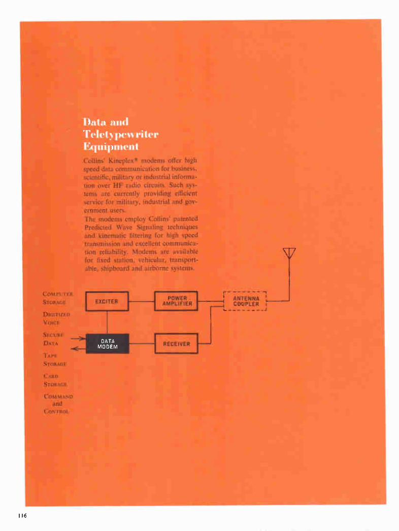
Data and Telet,,pewrite Equipment .
COMPUTER STORAGE
DIGITIZED VOICE
SECURE DATA
TAPE STORAGE
CARD STORAGE
COMMAND and
CONTROL
Collins' Kineplexe modems offer high speed data communication for business, scientific, military or industrial informa-tion over HF radio circuits. Such sys-tems are currently providing efficient service for military, industrial and gov-ernment users. The modems employ Collins' patented Predicted Wave Signaling techniques and kinematic filtering for high speed transmission and excellent communica-tion reliability. Modems are available for fixed station, vehicular, transport-able, shipboard and airborne systems.
DATA MODEM
ANTENNA J COUPLER I
1 I 6

Data and Teletypewriter Equipment
399R-1 Teletypem riter Adapter
Features Half or Full Duplex Operation
Synchronous or
Nonsynchronous Input
HF Compatibility
Applications Fixed Station
Transportable
Shipboard
The 399R-1 is a single channel teletypewriter adapter which
accepts nonsynchronous binary information from a key-
board, tape reader or storage unit. The information is then
converted to synchronous binary data for operation of a mod-
ulator-demodulator, such as the Collins TE-204A-2. Strap-
ping allows either a 5 ma or 60 ma teletypewriter loop to be
operated at 60 or 100 words per minute. The transmit and re-
ceive sections of the teletypewriter adapter can be employed
individually in half duplex operation or simultaneously in
full duplex operation.
SYNCHRONOUS OPERATION
Speed normalizer circuitry in the 399R- I synchronizes the
data input with timing from an external timing source, such
as the Collins 399S-1 or TE-204A-2, so that all bits are of
equal time duration and synchronized with the transmit tim-
ing used by the modulator.
RECEIVE CIRCUITS
In the receive mode, the loop keyer is driven by binary data
from either the TE-204A-2 modem or the 399S-1 adapter
(depending on interface parameters and system require-
ments) and keys a 60 ma or 5 ma loop circuit to operate a
teleprinter. The 399R-1 operates from synchronous or non-
synchronous data at 60 or 100 wpm.
TRANSMIT CIRCUITS
In the transmit mode, serial data via a 60 ma loop circuit is
accepted from a keyboard, tape reader or storage unit. Non-
synchronous Baudot coded information is converted to syn-
chronous data by the speed normalizer before entering the
399S-1 or TE-204A-2. The data is stored prior to conversion
and is read out synchronously with the 399S-1 or TE-204A-2
timing. The time difference in the lengths of nonsynchronous
7.42 Baudot data characters and the synchronous characters
is corrected by additional stop bits at the end of a synchro-
nous character as required.
TELETYPE OPERATE CONTROL
The teletype operate control is an automatic keying device
which operates from the transition on the incoming data. A
space or start bit in the data will cause the teletype operate
control circuit to actuate the transmit keyline. A delay circuit
prevents a release of the keyline relay for five or six seconds
to preclude opening of the line by subsequent data or momen-
tary line interruptions. If the net is already in use, a squelch
signal from the TE-204A-2 Modem prevents seizure of the
transmit line. Operation of the keyline relay also places the
TE-204A-2 in transmit mode. An external ground can be ap-
plied to override previous conditions.
SOLID STATE CIRCUITS
The 399R-1 employs solid state circuits with plug-in printed
circuit boards and modules.
Specifications TRANSMIT INPUT: Baudot coded information at 100 wpm or
60 wpm is synchronized with the speed normalizer. High or
low mark condition is provided by a strap option.
Option 1 — 60 ma/0 ma input on transmit loop circuit
(full duplex operation).
Option 2 — 60 ma/0 ma input on receive loop (half du-
plex operation; two-wire loop operation)
Option 3 — O y dc/-6 y dc data input.
Option 4 — O ma/5 ma input on transmit loop circuit,
Baudot nonsynchronous (full duplex operation).
Option 5 — O ma/5 ma input on transmit loop circuit,
Baudot nonsynchronous (half duplex operation).
TRANSMIT OUTPUT:
Option 1 — O y dc/-6 y dc synchronous Baudot data.
Option 2 — O y dc/-6 y dc nonsynchronous data ouput
(derived from loop circuit input).
RECEIVE INPUT: Low-level, Baudot coded dc serial data is
converted to high-level serial data to key either a 60 ma or
5 ma loop circuit at 100 wpm. High or low mark condition is
provided by a strap option.
RECEIVE OUTPUT: A 60 ma or 5 ma loop circuit drives a tele-
type printer or punch at 100 wpm.
TIMING: Transmit — externally derived 75 cycle square wave
for 100 wpm and 45.45 cycle square wave for 60 wpm
operation.
SPEED NORMALIZER: Converts nonsynchronous 60 or 100
wpm Baudot coded to synchronous information.
TRANSMIT LOOP CIRCUIT (strapable options) :
Option 1 — mark, 60 ma ± 10 ma (adjustable); space, 0 ma
117
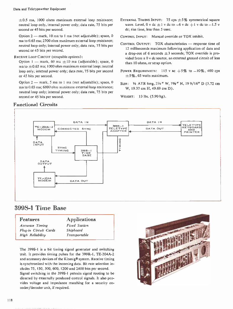
Data and Teletypewriter Equipment
+0.5 ma, 1000 ohms maximum external loop resistance;
neutral loop only, internal power only; data rate, 75 bits per
second or 45 bits per second.
Option 2 — mark, 10 ma to I ma ( not adjustable); space, 0
ma to 0.65 ma; 2700 ohm maximum external loop resistance;
neutral loop only; internal power only; data rate, 75 bits per
second or 45 bits per second.
RECEIVE LOOP CIRCUIT (strapable options) :
Option 1 — mark, 60 ma ± 10 ma (adjustable); space, 0
ma to +0.65 ma; 1000 ohm maximum external loop; neutral
loop only; internal power only; data rate, 75 bits per second
or 45 bits per second.
Option 2 — mark, 5 ma to 1 ma (not adjustable); space, 0
ma to 0.65 ma; 6800 ohm maximum external loop resistance;
neutral loop only; internal power only; data rate, 75 bits per
second or 45 bits per second.
Functional Circuits
EXTERNAL TIMING INPUT: 75 cps -±-5% symmetrical square
wave. Level, 0 v dc ±1 y dc to —6 v dc +1 y dc to —1.5 v
dc; rise time, less than 5 usec.
CONTROL INPUT: Manual override or TOX inhibit.
CONTROL OUTPUT: TOX characteristics — response time of
12 milliseconds maximum following application of data and
a drop-out of 6 seconds ±3 seconds; TOX override is pro-
vided from a 0 y dc source, an external ground circuit of less
than 10 ohms, or strap option.
POWER REQUIREMETS: 115 y ac +5% to —10%, 400 cps
±-5%, 65 watts maximum.
SIZE: 1/4 ATR long, 21/4 " W, 7h" H, 19 9/16" D (5.72 cm
W, 19.37 cm H, 49.69 cm D).
WEIGHT: 13 lbs. (5.90 kg).
TE- 204A- 2 MODEM
DATA INPUT
DATA IN
CORRECTED SYNC Nu
SYNC
TI MI NG
DATA OUTPUT
TE - 204A MODEM
3995-1 TI ME BASE
DATA OUT
399R-1 TE LE TYPE ADAPTER
DATA IN
DATA OUT
399S-1 Time Base
Features Accurate Timing
Plug-in Circuit Cards
High Reliability
Applications Fixed Station
Shipboard
Transportable
The 399S-1 is a bit timing signal generator and switching
unit. It provides timing pulses for the 399R-1, TE-204A-2
and accessory devices of the Kinesig system. Receive timing
is synchronized with the incoming data. Bit rate selection in-
cludes 75, 150, 300, 600, 1200 and 2400 bits per second.
Signal switching in the 399S-1 permits signal routing to be
directed by externally produced control signals. It also pro-
vides voltage and impedance matching for a security en-
coder/decoder unit, if required.
TE LE TYPE KEYBOARD
AND PR INTER
118

Data and Teletypewriter Equipment
HIGHLY STABLE CIRCUITS
The time base of the 399S-1 is a highly stable 3 mc oscillator
with frequency dividers and a synchronization correction
circuit. A regenerative divider reduces the frequency of the
master oscillator to 60 kc. Provision for an external 100 kc
signal to drive time base is optionally available. For transmit
timing pulse output, a digital divider further reduces this 60
kc to the desired bit rate (75, 150, 300, 600, 1200 and 2400
bits per second). The receive timing is achieved from the 60
kc by a similar set of dividers except that it is synchronized
with the incoming signal by comparison with sync pulses de-
rived from the incoming tones in the TE-204A-2 modem.
SIMPLIFIED MAINTENANCE
Reliability is greatly enhanced by the use of solid state cir-
cuits. Test points for all important circuit parameters are lo-
cated on the front panel. Removal of the dust cover permits
complete access to all plug-in circuit cards. All system con-
nections are completed through plugs at the rear of the unit.
Specifications
TYPE OF SERVICE: Full duplex or half duplex.
NUMBER OF CHANNELS: One.
BIT GATE RATES: 2400, 1200, 600, 300, 150 and 75 bits per
second.
CRYSTAL OSCILLATOR FREQUENCY: 3 mc.
POWER REQUIREMENTS: 103.5-120.75 v, 380-420 cps, 30
watts, maximum.
TEMPERATURE RANGE: —20° C to +55° C.
HUMIDITY RANGE: 0%-100%.
Size: 1/4 ATR long; 21/4 " W, 71/4 " H, 19 9/16" D (5.72 cm
W, 19.37 cm H, 49.69 cm D).
WEIGHT: 14 lbs. (6.35 kg).
TE-204A-2 Data Modern
Features Applications In-band Diversity
Inter-bit Diversity
Continuous Synchronization
Plug-in Circuit Cards
High Reliability
Fixed Station
Shipboard
Transportable
The TE-204A-2 is a highly reliable, synchronous data modu-
lator-demodulator for transmission of a single channel of se-
rial binary information at a 75 bit per second rate over HF,
VHF or UHF radio circuits.
Both 600 ohm and 150 ohm audio outputs enable the system
to be operated with most radio communication equipment.
Since this modem operates half duplex, two are required for
full duplex operation.
SYNCHRONOUS OPERATION
The modem provides continuous receive-synchronization
corrective-information independent of data content of the
message being received, including steady mark or space.
The TE-204A-2 will operate synchronously with a pulse
from the associated 399S- l Time Base.
HIGH RELIABILITY
The TE-204A-2 uses four tones with both in-band frequency
and inter-bit time diversity to minimize the effects of selective
fading and interference on RF circuits. Frequency diversity
is achieved through a two-tone time sharing system. Each bit
(either mark or space) is divided into two equal periods. Pre-
dicted Wave Detection provides a significant improvement
over nonsynchronous FSK in the presence of noise.
RECEIVE OPERATION
The received audio input frequencies to the TE-204A-2 are
935 or 1375 cps during the first half of a bit and 1815 or 2255
cps during the second half of a bit, depending upon whether
a "mark" or "space" was transmitted. The audio signal,
heterodyned to the 22 kc region, is applied to two keyed filter
detectors, one of which is tuned to the mark frequency and
the other to the space frequency. After integration, the filter
outputs are algebraically added ( for mark and — for
space) and the resulting information stored as a positive or
negative voltage, depending upon whether the mark or space
filter has the greater amplitude. In the second half of the bit, a second heterodyne frequency
(880 cps displaced) results in mixer output frequencies being
the same as for the first half of the bit, permitting use of a sin-
gle set of keyed filters. The outputs of the keyed filters during
the second half of the bit are detected, sampled and added as
before, and the resulting voltage added to the information
stored from the first half of the bit. The combined (sampled
119

Data and Teletypewriter Equipment
and stored) voltage from the two halves of the information bit is sampled, setting the received data output flip-flop.
Receive timing and the transmitted message are synchronized
using time diversity effect to drive the keyed filters and gate
the local oscillators.
Since the signals are separated in time and frequency, a dual
bandpass filter (one to pass the lower pair of tones trans-
mitted during the first half of the bit and the other to pass the
higher frequency pair of tones transmitted during the second
half of the bit) provides outputs which, when rectified and
added, form a square wave. The square wave is then applied
to a narrow band circuit tuned to the bit gating rate (75 cy-
cles per second) to provide an output signal to synchronize
the receive timing with the input data.
TRANSMIT OPERATION
During transmit operation, the modem accepts incoming
synchronous binary data bits and converts them to corre-
sponding audio output tones. These audio tones can be trans-
mitted over any 3 kc communication system. The modem
circuit configuration during transmit consists of the tone gen-
erators, oscillator-mixer circuit and timing circuit.
SIMPLIFIED MAINTENANCE
Reliability of the TE-204A-2 is greatly enhanced by the use
of solid state circuits and plug-in card construction. Test
points are located on the front panel. Removal of the dust
cover provides access to all circuit cards and wiring.
Specifications
TYPE OF SERVICE: Half duplex.
NUMBER OF CHANNELS: One.
NUMBER OF TONES: Four.
TONE GATING RATE: 75 cps.
TONE FREQUENCIES: Mark 1, 935 cps; Mark 2, 1815 cps;
Space 1, 1375 cps; Space 2, 2255 cps.
RESONATOR FREQUENCIES: Mark Data, 21.935 kc; Space Data, 22.375 kc.
TONE DURATION: 6.667 milliseconds.
BIT DURATION: 13.333 milliseconds.
INFORMATION DATA RATE: 75 bits per second.
CRYSTAL OSCILLATOR FREQUENCIES: 21.0 kc and 20.12 kc.
DC INPUT TRANSMIT DATA: Binary ZERO, —6 y dc; Binary
ONE, 0 y dc; Input, 5100 ohms, 500 uuf maximum.
TRANSMIT/RECEIVE LEVELS: Transmit Mode, —6 y dc; Re-
ceive Mode, 0 y dc.
POWER REQUIREMENTS: 103.5-120.75 v, 380-420 cps; 40
watts maximum.
ENVIRONMENTAL: Temperature Range, —20° C to +55° C;
Humidity Range, 0%-100%.
SIZE: 1/4 ATR long; 21/4 " W, " H, 19 9/16" D (5.72 cm
W, 19.37 cm H, 49.69 cm D).
WEIGHT: 14 lbs. (6.35 kg).
TE-202 Kineplex® Data Terminals
Features Parallel Binary Data
3200 Bit Per Second Rate
Wireline or Radio Compatibility
Solid State Circuits
Modular Construction
Applications Fixed Station
The TE-202 Data Terminals offer highly efficient data com-
munication on high frequency radio circuits. They will han-
dle up to 3200 bits per second of synchronous, parallel binary data over a standard 3 kc voice channel, which also can be de-
rived on wireline or microwave.
Up to 40 channels of data service are provided by the termi-
nals with data rates of 45, 56, 60, 75 or 80 bits per second on
each channel. This is ideal for 100 words per minute per
channel teletypewriter operation or as a high capacity data
link for computers, business machines, telemetry, supervisory control or other applications.
Designed for continuous operation, the terminals require
only periodic performance checks after initial start-up to as-
sure normal operation. Rack mounted, the TE-202 features
solid state circuitry and modular construction. Modules can
be removed or added in multiples of two channels to provide
a minimum of four and a maximum of forty channels of data service.
EQUIPMENT CONFIGURATION
Three TE-202 terminals are offered —the TE-202E-3 Trans-
mit Terminal, the TE-202F-6 Receive Terminal, and the
TE-202G-6 Diversity Receive Terminal. A data channel
tester, a power control and a patch panel are standard equip-
ment on all terminals.
Each terminal furnishes simplex data service. The transmit terminal, combined with the TE-202F-6 Receive Terminal, provides duplex data service, or combined with the TE-
202G-6, furnishes duplex diversity data service.
On long communication links, a duplex terminal can be used
as an unattended digital relay station.
TE-202E-3 TRANSMIT TERMINAL
The transmit terminal generates 20 audio tones spaced 110
120

Data and Teletypewriter Equipment
TE-202G-6 Diversity Receive Terminal
cycles apart in a frequency range of 605 to 2695 cps. A 2915
cps synchronizing tone is also generated. Phase multiplexing
combines two incoming data channels onto a single tone, and
up to 40 separate data channels can be phase multiplexed
onto the 20 tones. Data channels can be grouped together for
the transmission of parallel data. A patch panel permits con-
nection of any input line to any one of the data channels.
TE-202F-6 RECEIVE TERMINAL
The TE-202F-6 receives up to 40 channels of parallel data.
Audio tones are separated from the received signal by kine-
matic filtering in both the time and frequency domains. The
tones are decoded and converted into binary data. In decod-
ing, two keyed filters are used for each tone. While one is be-
ing driven by the signal, the other stores the previously re-
ceived phase. At the end of the drive period, the detector cir-
cuitry converts the phase difference between the two signals
into binary information.
TE-202G-6 DIVERSITY RECEIVE TERMINAL
The TE-202G-6 uses diversity to protect against multipath
and selective fading encountered in HF radio communica-
tion. Two receivers detect, separate, decode and convert au-
dio tones into binary data. The diversity unit reassembles the
data through continuous linear combination of the signals
for delivery to output data converters.
The operating characteristics of the two diversity receivers
are identical to those of the TE-202F-6.
DATA CHANNEL TESTER
The data channel tester provides back-to-back testing or test
with a remote terminal over the voice channel for preventive
maintenance or fault location. Visual error count indicator
lamps quickly isolate marginal or fault conditions by group,
channel and state (binary one or zero). Modular construc-
tion of the TE-202 permits rapid correction of the indicated
marginal or fault condition.
Specifications
TRANSMIT INPUT: 1-40 channels, parallel, synchronous bi-
nary data signals, each at 45, 56, 60, 75 or 80 bits per second.
Data inputs are voltage levels with respect to ground; —12
dc ± 10% for binary zero (0) and —21 y dc ± 10% for bi-
nary one (1). Input impedance is 12,000 ohms.
TRANSMIT OUTPUT: Composite signal composed of 20 phase-
shifted audio tones and one synchronizing tone. The 20 data
tones, spaced 110 cycles apart, range in frequency from 605
cps to 2695 cps. The 2915 cps synchronizing tone is on-off
modulated at 1/2 the transmitted data rate. Output level is
—1 dbm maximum in 600 ohms with peaks to +16 dbm.
TIMING: The transmit time base accepts a 100 kc sine wave
from a high stability standard and provides timing signals for
the transmit terminal and associated equipment. Data timing
is a symmetrical square wave, 0 y +0.5 y to —10 +0.5 v.
with repetition rate equal to data rate.
POWER REQUIREMENTS: 115 y ac -a-.10%, single phase, 60
cps, 2.5 amps.
TE-202F-6. TE-202G-6 RECEIVE TERMINALS
RECEIVE INPUT: Composite signal composed of 20 phase-
shifted audio tones and one synchronizing tone. The 20 data
tones, spaced 110 cycles apart, range in frequency from 605
cps to 2695 cps. The 2915 cps synchronizing tone is on-off
modulated at one-half received data rate. Nominal input lev-
el is —22 dbm. Input impedance is 600 ohms at 1000 cps.
RECEIVE OUTPUT: 1-40 channels, parallel, synchronous bi-
nary data signals, each at 45, 56, 60, 75 or 80 bits per second.
121

Data and Teletypewriter Equipment
Data outputs are voltage levels with respect to ground; —12
v dc ±- 10% for binary zero (0) and —21 v dc +10% for
binary one (1). Output load impedance is 10,000 ohms.
TIMING: The receive time base accepts a 100 kc sine wave
from a high stability standard and provides timing signals for
the data receiver and associated equipments. Data timing is
a symmetrical square wave, 0 y +0.5 y to —10 y +0.5 v.
Timing signal for operation and synchronization of external
equipment is available at the output data rate.
ASSOCIATED HF RADIO EQUIPMENT
o '
AUDIO RESPONSE: 2.5 db, 450-3050 cps; 30 db, 4000 cps
above carrier; 40 db, 400 cps below carrier.
DIFFERENTIAL DELAY: 0.5 millisecond, 800-3050 cps; 0.9
millisecond, 500-800 cps.
FREQUENCY STABILITY: 1 part in 10' per day.
FREQUENCY DEVIATION: Not more than 0.5 cps, audio output.
PHASE STABILITY: Not more than 4° per bit-period.
SSB DISTORTION: At full PEP, all distortion products are 35
db below either tone of a two-tone test signal.
SPURIOUS SIGNALS: At least 50 db below rated PEP.
NOISE: 40 db below either tone of a two-tone test signal.
AUDIO INPUT: 600 ohms.
ALC: Adjustable to more than 90% of PEP.
RECEIVER CHARACTERISTIC S
AUDIO RESPONSE: 2.5 db. 450-3050 cps; 30 db, 4000 cps
above carrier; 40 db, 400 cps below carrier.
DIFFERENTIAL DELAY: 0.5 millisecond, 800-3050 cps; 0.9
millisecond, 500-800 cps.
FREQUENCY STABILITY: 1 part in 10'' per day.
FREQUENCY DEVIATION: Not more than 0.5 cps, audio output.
PHASE STABILITY: Not more than 4° per bit-period.
INTERMODULATION DISTORTION: 3rd order distortion prod-
ucts are 40 db below either tone of a two-tone test signal.
AUDIO DISTORTION: Not more than 1% total.
SPURIOUS SIGNALS: More than 80 db down including images.
AUDIO OUTPUT: 600 ohms, 8 db maximum variation due to
AGC control.
AGC: Attack and release time constant of 200 milliseconds.
GAIN STABILITY: Not more than 2 db difference between the
audio output levels of the dual diversity receiver.
WIRELINE REQUIREMENTS
FREQUENCY RESPONSE: 3 db, 600-2700 cps; 6 db, 300-3000
cps.
DIFFERENTI&L DELAY: 1.5 milliseconds, 600-2700 cps; 3.0
milliseconds, 500-3000 cps.
CIRCUIT NET Loss: 20 db.
NET Loss VARIATION: ± 8 db.
LINE IMPEDANCE: 600 ohms at 1000 cps.
FREQUENCY TRANSLATION M AXIMUM: -± I cps.
BROADBAND NOISE (3 kc nominal bandwidth) : 20 db.
SUBSCRIBER STATION PROTECTION: Normal devices.
700B-2 Teletypewriter Converter
Features No Adjustments
Solid State
Small Size
Applications Fixed Station
Shipboard
Mobile
The 700B-2 is a compact teletypewriter converter which will
change two-tone frequency-shift keyed signals at 1575 cps
and 2425 cps to the binary dc levels required to actuate a
teletypewriter at speeds to 100 words per minute. It also con-
verts the teletypewriter binary dc output to two-tone audio
information that can be used half duplex to modulate a trans-
mitter in the frequency shift keying mode.
A choice of 2-wire 60 ma, 4-wire 60 ma or AN/AGC-1 tele-
typewriter equipment can be accommodated by simply
changing the connection of jumper straps in the unit. Audio
output impedances of either 150 or 600 ohms can be se-
lected by jumpers on the rear connector.
The 700B-2 consists of four plug-in modules on an aluminum
chassis housed in a short 1/4 ATR case. All electrical connec-
tions are made through a single connector located at the rear.
Test points on each module aid in performing maintenance
checks. Reliability is greatly enhanced by the use of solid
state components.
122 Available only on a production contract.

Data and Teletypewriter Equipment
Specifications
SIGNAL INPUT-AUDIO
FREQUENCY: Mark, 2425 cps; space, 1575 cps.
SENSITIVITY: 100 MV ID 4 y rms input levels at 600 ohms
1000 ohms.
MOUNTING: ARINC Specification 404.
OPERATING CONDITIONS
or AMBIENT TEMPERATURE RANGE: —40° C to +50° C.
SIGNAL OUTPUT-AUDIO
FREQUENCY: Mark, 2425 cps; space, 1575 cps.
OUTPUT: 15 milliwatt level at 150 ohms or at 600 ohms.
TELETYPEWRITER: Standard 60 ma 2- Or 4-wire loop.
POWER: 115 v 5%, 400 cps ±5 % , 1 phase, 28 watts; 26.5
dc ±20%, 90 ma nominal.
AMBIENT HUMIDITY RANGE:
AMBIENT ALTITUDE:
0%-95%.
Up to 15,000 ft.
SHOCK CONDITIONS: Will meet Munson road test.
VIBRATION: MIL-STD-167.
SIZE: Standard short 1/4 ATR case, 23/4 " W, 7 49/64" H,
15 3/16" D (6.03 cm W, 19.72 cm H, 36.04 cm D).
WEIGHT: 9 lbs. (4.08 kg).
700C-1 Telet> pew riter Adapter kit
Features Easily Installed
Solid State
Small Size
Applications Field Use
Fixed Station
Mobile
Used in conjunction with the AN/PRC-47, the 700C-1 Tele-
typewriter Adapter Kit provides a single channel of half du-
plex communication using an SSB radio circuit (two-wire
operation). Design features include compact construction,
solid state components, electronic keyer and integral loop
current power supply. A blower and air filter is included to
permit continuous duty transmit operation of the AN/PRC-
47. In the transmit mode, the binary output of a teletype-
writer is converted to two-tone audio signals for modulating
the transmitter. In the receive mode, the two-tone FSK sig-
nals in the audio range are converted to dc binary levels for
operation of a 100 wpm teletypewriter. The filter charac-
teristics will allow RF frequency translation errors or Dop-
pler shift.
The 700C-1 is easily installed on the front panel and re-
quires no wiring changes, adjustments or tuning. A switch
and potentiometer are used to select the loop current option
and adjust the current to the proper value. The teletype-
writer can be located up to one mile from the AN/PRC-47.
Terminals are included for connection of a remote push-to-
talk switch.
Specifications SIGNAL INPUT-AUDIO: Frequency — Mark, 2425 cps; space,
1575 cps. Sensitivity —50 mw into 300 ohms.
SIGNAL INPUT-DC BINARY: DC Binary — 60 ma mark, 0 ma
space (option 1); 20 ma mark, 0 ma space (option 2).
SIGNAL OuTPu-r-Aunto: Frequency — Mark, 2425 cps; space,
1575 cps. Output —0.1 y rms at 50 ohms.
SIGNAL OUTPUT-BINARY: Binary — 60 ma mark, 0 ma space
(option 1); 20 ma mark, 0 ma space (option 2).
TELETYPEWRITER EQUIPMENT OPTIONS: ( 1) Standard 60 ma
teletypewriter. (2) AN/AGC-1 teletypewriter. (3) Tele-
printer Model 104 "MITE."
POWER: Obtained from AN/PRC-47; 25 watts (includes
cooling air blower necessary for continuous duty operation
in transmit function).
OPERATING CONDITIONS: Ambient Temperature — —40° C to
+60° C. Ambient Humidity — 0%-90% relative humidity.
Ambient Altitude — Sea level to 12,000 ft. Shock Conditions
— 20 g peak. Vibration — 5 g, 10-55 cps. Bias Distortion
5% maximum.
Size: 4¼" W, 33/4 " H, 6 7/8" D (10.8 cm W, 9.53 cm H,
17.46 cm D).
WEIGHT: 3 lbs. (1.36 kg).
Available only on a production contract. 123

TE-212 Digital Data Modem
- Features Full Duplex Transmission
2400 Bit Per Second Rate
Diversity Receive Function
Solid State Circuits
Applications Fixed Station
Airborne
The TE-212 Digital Data Communication Modem is a solid
state, full duplex transmitter and diversity receiver capable of
a 2400 bit per second data rate over a 3 kc bandwidth with
HF radio equipment.
The TE-2I2 communicates digital data between aircraft and
ground station or between ground stations. It superimposes
this data on four audio tones, which are separated by 440 cy-
cles in a frequency range of 935 to 2255 cps.
TE-212D
At the diversity receive terminal, digital data is extracted
from the audio tones, using Kineplexe techniques, regener-
ated and delivered to external equipment in either serial or
parallel form.
HIGH RELIABILITY
Phase shift modulation and Collins patented Predicted Wave
Detection techniques yield a signal-to-noise ratio four times
(6 db) better than frequency modulated systems and make
optimum use of narrow bandwidths. Reliability and ease of
maintenance are assured by solid state components and draw-
er-mounted, plug-in modular circuit cards. This packaging
technique permits custom, rack or cabinet arrangement.
Diversity operation is provided for additional communica-
tion reliability over radio circuits that are subject to selective
fading. Diversity operation provides frequency or space di-
124

Data and Teletypewriter Equipment
versity through continuous, linear combination of the re-
ceived channels.
An automatic level control maintains input line level value
by automatically correcting for long term line variations. A
phase delay compensator network corrects the phase delay
inherent in transmission equipment.
FLEXIBLE DATA RATES
The TE-212 is designed for continuous, unattended, auto-
matic, full duplex operation in any of five, dial-selected, data
rate modes: 600, 1200 or 2400 bits per second at 3.3. milli-
second bit lengths, or 600 or 1200 bits per second at 6.7 milli-
second bit lengths. These high speed, flexible data rates plus
built-in reliability make the TE-212 Data Communication
Modem the solution to rigorous data transmission applica-
tions wherever sustained, accurate performance is required.
INTEGRAL TEST FACILITY
The integral test facility compares the received data pattern
with the transmitted test pattern and provides visual error
indication. Regenerated in the receiver in synchronism with receive timing, the test pattern permits back-to-back testing,
or system testing over a voice facility. In the test mode, re-
ceived serial data on any one of the eight parallel data chan-
nels can be monitored.
TE-210D-2 (non-diversity)
ALARMS
Alarms provide relay contact closure for loss of input serial
data rate timing, loss of serial input data, loss of serial output
data, improper transmit and receive levels.
Specifications
DATA INPUT (DIGITAL)
VOLTAGE LEVEL: Serial — binary zero (0), —1.0 v to +0.25
V; binary one (1), +3.6 v to +6.0 v. Parallel — binary zero
(0), —4.0 y to —6.25 v; binary one (1), +1.0 y to
—1.0 v.
IMPEDANCE: Serial — 5,000 ohms nominal. Parallel — 10,000
ohms nominal.
DATA OUTPUT (DIGITAL)
VOLTAGE LEVELS: Serial — binary zero (0), —1.0 v to +0.25
V; binary one (1), +3.6 y to +6.0 v. Parallel—binary zero
(0), —5.5 v to —6.5 v; binary one (1), +0.25 v to —0.2 v.
IMPEDANCE: 600 ohms maximum output impedance, shunt
capacity 300 uuf maximum; 600 ohms load impedance.
AUDIO INPUT/OUTPUT
Composite audio signal consisting of the following frequen-
cies: 600/3 bit per second rate — 1375 cps; 1200/3 bit per
second rate — 1375 and 1815 cps; 2400/3 bit per second
rate —935, 1375, 1815 and 2255 cps; 600/6 bit per second
rate — 1375 and 1815 cps; 1200/6 bit per second rate —
935, 1375, 1815 and 2255 cps.
IMPEDANCE: 600 ohms ±20% from 900 cps to 2300 cps.
LEVEL: Input — variable, —35 dbm to +5 dbm. Output —
variable, —20 dbm to +4 dbm.
EXTERNAL CLOCK INPUT: 100 kc, with frequency stability of
106 per day, or greater, 5 y rms minimum, 5000 ohms.
EXTERNAL TIMING: Provided by internal 100 kc crystal oscil-
lator. Data rate timing input — bipolar square wave, 2.9-6.8
y peak-to-peak at 600, 1200 or 2400 cps, 5000 ohms nominal.
Data rate timing output — bipolar square waves, 3.6-6.0 v
peak-to-peak at 600, 1200 or 2400 cps, 600 ohms maximum.
300 cps and 600 cps input/output — 0 to —6 v, 10,000 ohms
input impedance; 600 ohms output impedance.
COOLING: An internal blower and distribution for each en-
closure. Panel controlled air paths maintain suitable internal
operating temperatures.
POWER REQUIREMENTS: 100-125 y ac rms, 47-63 cps, single
phase, 250 watts maximum.
OPERATING MODE: Full duplex, continuous, unattended at
600, 1200 or 2400 bit per second rates.
RELIABILITY: Greater than 2500 hours MTBF (Mean Time
Between Failures); less than 15 minutes MTR (Mean Time
to Repair). Preventative maintenance less than 5 hours per
month for continuous operation.
ENVIRONMENTAL (OPERATING)
TEMPERATURE: 0° —52° C.
HUMIDITY:
ALTITUDE:
VIBRATION:
0%-80% relative without condensation.
0-15,000 ft.
MIL-T-4807A.
225
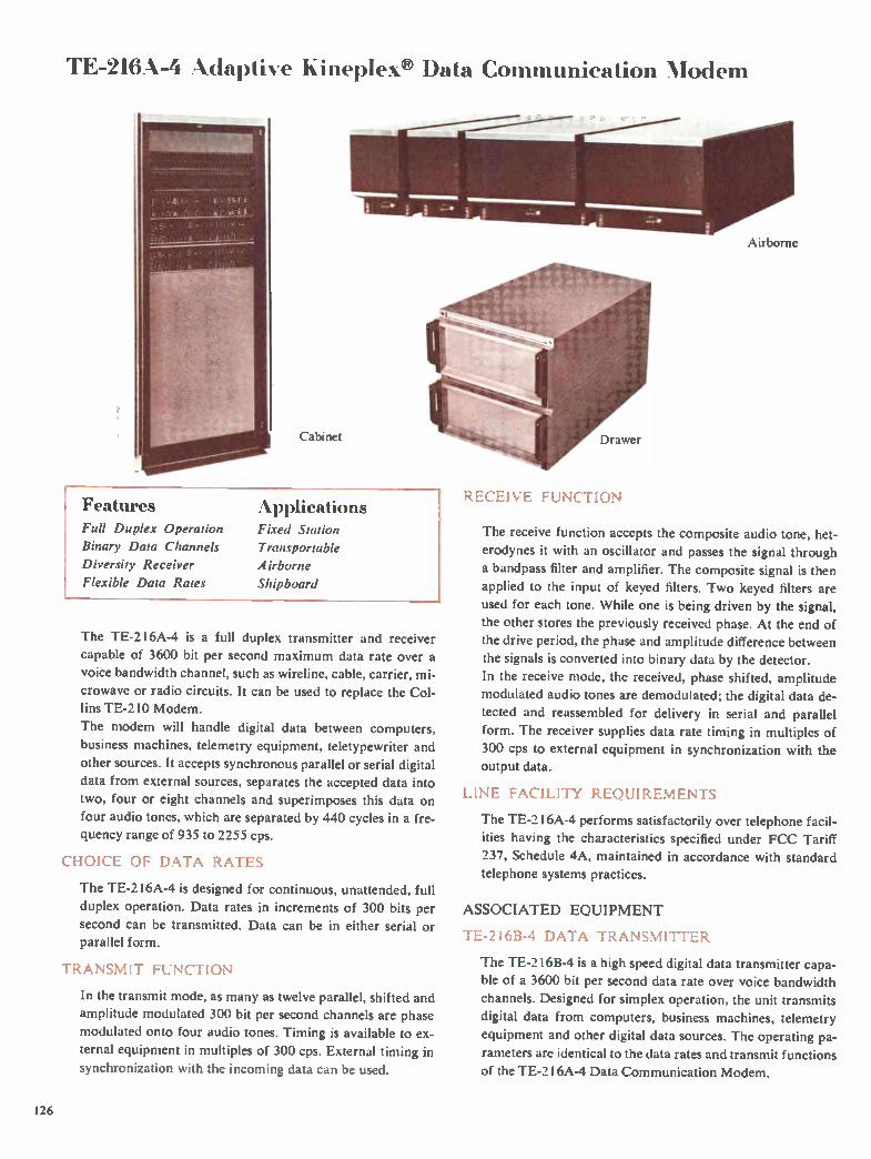
TE-216A-4 Adaptive Kineplex® Data Communication Modem
Cabinet
RECEIVE FUNCTION Features Full Duplex Operation
Binary Data Channels
Diversity Receiver
Flexible Data Rates
Applications Fixed Station
Transportable
Airborne
Shipboard
The TE-2 1 6A-4 is a full duplex transmitter and receiver
capable of 3600 bit per second maximum data rate over a
voice bandwidth channel, such as wireline, cable, carrier, mi-
crowave or radio circuits. It can be used to replace the Col-
lins TE-210 Modem.
The modem will handle digital data between computers,
business machines, telemetry equipment, teletypewriter and
other sources. It accepts synchronous parallel or serial digital
data from external sources, separates the accepted data into
two, four or eight channels and superimposes this data on
four audio tones, which are separated by 440 cycles in a fre-quency range of 935 to 2255 cps.
CHOICE OF DATA RATES
The TE-216A-4 is designed for continuous, unattended, full
duplex operation. Data rates in increments of 300 bits per
second can be transmitted. Data can be in either serial or parallel form.
TRANSMIT FUNCTION
In the transmit mode, as many as twelve parallel, shifted and
amplitude modulated 300 bit per second channels are phase
modulated onto four audio tones. Timing is available to ex-
ternal equipment in multiples of 300 cps. External timing in
synchronization with the incoming data can be used.
Airborne
The receive function accepts the composite audio tone, het-erodynes it with an oscillator and passes the signal through
a bandpass filter and amplifier. The composite signal is then
applied to the input of keyed filters. Two keyed filters are used for each tone. While one is being driven by the signal,
the other stores the previously received phase. At the end of
the drive period, the phase and amplitude difference between the signals is converted into binary data by the detector.
In the receive mode, the received, phase shifted, amplitude
modulated audio tones are demodulated; the digital data de-
tected and reassembled for delivery in serial and parallel
form. The receiver supplies data rate timing in multiples of
300 cps to external equipment in synchronization with the output data.
LINE FACILITY REQUIREMENTS
The TE-216A-4 performs satisfactorily over telephone facil-
ities having the characteristics specified under FCC Tariff
237, Schedule 4A, maintained in accordance with standard
telephone systems practices.
ASSOCIATED EQUIPMENT
TE-2 I 6B-4 DATA TRANSMITTER
The TE-2I6B-4 is a high speed digital data transmitter capa-
ble of a 3600 bit per second data rate over voice bandwidth
channels. Designed for simplex operation, the unit transmits
digital data from computers, business machines, telemetry
equipment and other digital data sources. The operating pa-
rameters are identical to the data rates and transmit functions
of the TE-216A-4 Data Communication Modem.
126

Data and Teletypewriter Equipment
TE-216C-4 DATA RECEIVER
The TE-216C-4 is a high speed digital data receiver capable
of detecting the signal transmitted by the Collins TE-21 6A-4
Data Communication Modem or the Collins TE-2 I 6B-4
Data Transmitter. Designed for simplex operation, the
TE-216C-4 can receive, detect and regenerate the data trans-
mitted over nominal 3 kc bandwidth channels. The TE-216C-
4 delivers the data to external equipment in serial or parallel
form. The operating parameters are identical to the receive
functions of the Collins TE-216A-4.
TE-216A-20 Adaptive Kineplex® Data Modem
Features Applications Full Duplex Fixed Station
Accepts Binary Data Shipboard
Diversity Receiver Transportable
Flexible Data Rates Airborne
Kineplexg Techniques
The TE-216A-20 is a highly efficient data terminal for use
over HF radio circuits. Up to 4500 bits per second of syn-
chronous, parallel binary data can be transmitted over a
standard 3 kc voice channel. The equipment can be used also
on wireline or microwave circuits.
It offers a wide range of transmission rates in full duplex op-
eration. Up to 60 channels of data service are provided by
the terminal with data rates of 75 bits per second on each
channel. The TE-2 I 6A-20 is ideally suited for 100 word per
minute per channel teletypewriter operation or as a high ca-
pacity data link for computers, business machines, tele-
metery, supervisory control or other similar applications.
Other bit rates are optionally available. The TE-216A-20 re-
places the TE-202.
HIGH RELIABILITY
Designed for continuous operation, the terminal requires
only periodic performance checks after initial start-up to as-
sure normal operation. Rack mounted, the Collins TE-21 6A-
20 features solid state circuitry, integrated cooling and pow-
er. Transmit and receive circuit cards can be removed or
added in multiples of two channels to provide a minimum of
two and a maximum of 60 channels of data service.
EQUIPMENT CONFIGURATIONS
Three TE-2 1 6A-20 terminal configurations are offered: the TE-216B-20 Transmit Terminal, the TE-216C-20 Receive
Terminal, and the TE-2 I 6D-20 Diversity Receive Terminal.
The TE-216B-20 Transmit Terminal, combined with the
TE-216C-20 Receive Terminal, provides duplex data serv-
ice, or combined with the TE-216D-20, furnishes duplex di-
versity data service. On long communication links, a duplex terminal can be used
as an unattended digital relay station.
oft .46.11
11.6g,11 ,it
•I HUI HUM ii léllIthi,r.0 1
I..) I I I I I I 1
11 4i • : 14.. Iiiii ii.11 II .
,, .1
:
il II II ,
• •
• ..... I 1111,
1.11Iii..1
I
• . .
. . .. ...
1,11.11111 À,. i I .•.
..........
_
Specifications TE-216B-20 TRANSMIT TERMINAL
TRANSMIT INPUT: Up to 60 channels, parallel or optionally
serial synchronous binary data signals. Data inputs are volt-
age levels with respect to ground; +3y dc for binary zero (0)
and 0 y dc for binary one ( I). Input impedance is 600
ohms. Parallel input is 75 bits per second per channel maxi-
127

Data and Teletypewriter Equipment
mum; serial, 4500 bits per second with other rates optional in
either burst or continuous format.
TRANSMIT OUTPUT: Composite signal composed of 20 phase-
shifted and amplitude-modulated audio tones. The 20 data
tones, spaced 110 cycles apart, range in frequency from 605
cps to 2585 cps. Output level is —I dbm maximum into a 600
ohm line with peaks to +10 dbm.
TIMING: The transmit time base operates from either a 100 kc
sine wave from a high stability standard or an internal refer-
ence frequency and provides timing signals for the transmit
terminal and associated equipment. Data timing is available
in multiples of 75 cps for either serial or parallel operation.
TE-2 I 6C-20 RECEIVE TERMINAL
The receive terminal accepts the composite audio tones, het-
erodynes them and passes the signal through a bandpass
filter and amplifier. The composite signal is then applied to
the input of the keyed filters. Two keyed filters are used for
each tone. The received, phase shifted amplitude modulated
audio tones are demodulated. The digital data after detection
is reassembled for delivery in serial or parallel form. The re-
ceiver supplies data rate timing for serial or parallel operation
to external equipment in synchronization with the ouput data.
TE-2 I 6D-20 FULL DUPI.EX WITH DIVERSITY
TE-216D-20 terminals can be operated over any voice fa-
cility meeting the specifications listed below under transmis-
sion facility requirements. TE-216D-20 equipment complies
with good telephone engineering practice as to transmitting
levels, balance and dielectric strength. Normal subscriber
station protection devices are satisfactory in this application.
TRANSMISSION FACILITY REQUIREMENTS
HF RADIO EQUIPMENT
TRANSMITTER CHARACTERISTICS
AUDIO RESPONSE: 2.5 db, 500-2700 cps; —30 db, 4000 cps
above carrier; —40 db, 400 cps below carrier.
DIFFERENTIAL DELAY: 1.0 millisecond, 500-2700 cps.
FREQUENCY STABILITY: 1 part in 108 per day with synchroni-
zation disabled; 1 part in 10" per day with continuous syn-
chronization.
SSB DISTORTION: At full PEP, all distortion products are 35
db below either tone of a two-tone test signal.
NOISE: 40 db below either tone of a two-tone test signal.
AUDIO INPUT: 600 ohms.
RECEIVER CHARACTERISTICS
AUDIO RESPONSE: 2.5 db, 500-2700 cps.
DIFFERENTIAL DELAY: 1.0 millisecond, 500-2700 cps.
FREQUENCY STABILITY: 1 part in 108 per day (see above)
INTERMODULATION: 3rd order distortion products are 40 db
below either tone of a two-tone test signal.
SPURIOUS SIGNALS: Inband —40 db down.
AUDIO OUTPUT: 600 ohms, 8 db maximum variation due to
AGC control.
AGC: Attack and release time constant of greater than 200
milliseconds.
WIRELINE REQUIREMENTS
FREQUENCY RESPONSE: 3 db, 500-2700 cps.
DIFFERENTIAL DELAY: 4.0 milliseconds, 500-2700 cps.
CIRCUIT NET Loss: 30 db.
NET Loss VARIATION: +8 db.
LINE IMPEDANCE: 600 ohms at 1000 cps.
BROADBAND NOISE (3 kc nominal bandwidth) : 20 db.
Selective Calling System
Features Flexible Coding
Ease of Operation
Synchronous Timing
Applications Fixed Station
Path Evaluation
The Selective Calling System provides a continuous check of
an entire communication network operational status by ob-
taining an automatic interrogation response from individual
stations. It eliminates the need for continuous manual moni-
toring of receivers at each station in large HF communica-
tion systems. The SELCAL can be integrated into fully au-
tomatic calling and propagation evaluation systems.
It can also be employed for selective calling of individual
stations, manual polling, simultaneous calling of all stations
or automatic response to a selective call from another station
in the network.
The SELCAL consists of an encoder/decoder and modem
which convert digital coding to analog information for radio
transmission and which process incoming data to determine
message content.
Receive function is activated by a preamble code which dis-
tinguishes actual pertinent data from noise or voice trans-
missions. Time and frequency diversity operation minimize
the effects of multipath distortion and selective fading, greatly
increasing the reliability on long HF communication paths.
128 Available only on a production contract.

SIGNAL GENERATOR
Test Equipme Collins specialized' test equipment in-cludes spectrum analyzers to facilitate rapid and accurate measurement in sin-gle sideband systems. Equipment is also available for maintenance and calibra-tion of systems using the 618T Trans-ceiver and module testing of Collins au-tomatic antenna couplers. Accurate calibration and uniform main-tenance procedures assure peak system operating conditions and increased re-liability. Precise, standard adjustment of system components facilitates module interchangeability between equipment.
618T TRANSCEIVER
AUDIO OSCILLATOR
678P-1 TEST SET
678Z-1 TEST SET
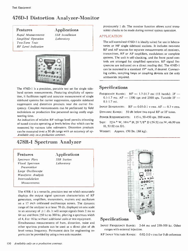
Test Equipment
4761)-1 Distortion Aital>zer-Monitor
Features Applications Rapid Measurements SSB Installation
Simplified Operation Laboratory
Two-Tone Tests
RF Level Indication
proximately 1 db. The monitor function allows aural trans-
mitter checks to be made during normal system operation.
APPLICATION
The self-contained 476D- I is ideally suited for use in labora-
tories or HF single sideband stations. It includes two-tone
RF and AF sources for separate measurements of receivers,
transmitters, RF or AF amplifiers, modulators or complete
systems. The unit is self-checking, and the front panel con-
trols are arranged for simplified operation. RF signal fre-
quencies are indicated on a direct reading dial. The 476D-1
can be mounted in a standard 19" rack, if desired. Connect-
ing cables, sampling loops or coupling devices are the only
accessories required.
The 476D-1 is a precision, portable test set for single side- Specifications band system measurements. Featuring simplicity of opera- FREQUENCY RANGE: RF — 1.7-31.7 mc (15 bands). IF —
tion, it facilitates rapid and accurate measurement of single 0.1-1.7 mc. AF — 1500 cps and 2500 cps. Tunable IF — sideband systems for carrier suppression, opposite sideband 0.1-1.7 mc.
suppression and distortion products near the carrier fre-INPUT SENSITIVITY: RF — 0.03-0.1 y rms. AF —0.3 y rms. quency. Complex measurements can be performed by field
technicians or production line personnel saving costly engi- DYNAMIC RANGE: 50 db below two equal RF or IF tones.
neering time. POWER REQUIREMENTS: I 15 v, 50-450 cps, 200 watts. An indication of relative RF voltage level permits trimming
SIZE: 22 1/4 " W, 18 1/2 " H, 20 7/8" D (56.52 cm W, 46.99 cm of tuned circuits operating at levels below that which can be
H, 53.02 cm D). measured by vacuum tube voltmeters. Distortion products
can be measured over a 50 db range with an accuracy of ap- WEIGHT: Approx. 150 lbs. (68 kg). Available only on a production contract.
478R-1 Spectrum Analyzer
Features .Applications Spectrum Plots SSB Station
Visual Spectrum Laboratory
Presentation
Large Oscilloscope
Waveform Analysis
Intermodulation
Measurements
The 478R-I is a versatile, precision test set which accurately
displays the output signal spectrum characteristics of RF
generators, amplifiers, transmitters, exciters and oscillators
on a 17 inch calibrated oscilloscope screen. The dynamic
range of the analyzer is at least 70 db, displayed on one scale
to an accuracy of -± 1 db. It will accept signals from 2 mc to
64 mc and from 250 kc to 300 kc, plotting a spectrum width
of 4, 8 or 16 kc without additional coils or test equipment.
Simultaneous measurements of hum, distortion, noise and
other spurious products can be used as a direct plot of db
level versus frequency. Permanent data for engineering re-
ports can be provided by using a two-axis recorder.
e de 'la L t....,
.33 I;J
•:.*) elbag• ••:• r 4,**
Specifications INPUT FREQUENCY RANGE: 2-64 mc and 250-300 kc. Other
ranges with external injection.
RF INPUT VOLTAGE RANGE: 0.02-5.0 y rms for 0 db reference
130 Available only on a production contract.

Test Equipment
level; 70 db dynamic range; RF signals below 6 uy can be
detected at some frequencies.
SCANNING BANDWIDTHS: 4, 8 or 16 kc.
SCANNING TIME: 2-60 seconds. Manual scanning of spectrum
can be employed.
REsowrioN: 60 cps sidebands can be separated from the
carrier frequency throughout the full range.
CALIBRATION ACCURACY: Vertical — within ± 1 db from 0 to
—70 db; 10 inches of usable height.
TWO-TONE TEST SIGNAL: Continuously variable audio oscil-
lators provide input signals. Output is 3 y rms for each tone
with up to 1 1 1 db of attenuation in 0.1 db steps into a 600
ohm external load.
POWER REQUIREMENTS: 115 v, 60 cps, 1200 va (230 v and/or
50 cps on special order).
SIZE: 22" W, 69" H, 26" D (55.88 cm W, 175.26 cm H,
66.04 cm D).
WEIGHT: 600 lbs. (272.16 kg).
618T HF Transceiver Test Sets
Features Dynamic Tests
Uniform Adjustments
System Tests
Rapid Maintenance
Applications Shop Maintenance
Field Maintenance
The 678P-1 Test Harness, 678Y- I Maintenance Kit and
678Z- l Function Test Set, used with standard communica-
tion test equipment, provide a complete test facility for 618T,
AN/ARC-94 or AN/ARC-IO2 Transceivers.
The AN/ARM-73 and MK-773 utilize groupings of these
basic test equipments in lightweight, rugged, Fiberglas car-
rying cases for field and tactical applications. The AN/
ARM-73 ( 678P-2) consists of the 678P-1 and associated ca-
bles, while the MK-773 (678Y-3) includes 678Y- 1 com-
ponents, the 678Z-1 and a kit of tools especially suited for
maintenance of the 618T Transceivers.
The test sets assure peak operating condition of the commu-
nication systems by the use of uniform maintenance proce-
dures. Precise standard adjustment of system components
also facilitates modules which interchange between equip-
ments, allowing more effective utilization and rapid over-all
system maintenance.
AN/ARM-73 MK-773
678P- I TEST BENCH HARNESS SET
The 678P- l Test Bench Harness includes a test panel unit,
together with cables and adapters. It is rugged, versatile and
simple to use, allowing a rapid test of the complete system.
Cable connectors are located on a rear deck away from op-
erational controls. A 714E control unit mounts directly in the
front panel. A directional wattmeter measures forward and
reflected power. Both resistive and capacitive dummy RF
loads are provided.
Power Requirements: Determined by transceiver being
tested. Size: 81/2 " W, 9 9/16" H, 16" D (21.59 cm W, 24.29
cm H, 40.64 cm D). Weight: 25 lbs. (11.34 kg).
678P-1
678Y-1 MAINTENANCE KIT
The 678Y- l Maintenance Kit consists of nine module ex-
tenders, a shipping and storage case, and a complete set of
special tools, adapter plugs, cables and detectors to facilitate
alignment and adjustment of the 618T Transceiver. The ex-
tender plugs into the equipment instead of the module to be
tested, and the module then plugs into the extender. It is then
located 6" from the 618T, AN/ARC-94 or AN/ARC-102
chassis, permitting access to all components during operation.
All modules except the power amplifier and high voltage
supply can be tested. Air flow cooling requirements and the
presence of dangerously high voltages preclude the use of
extenders for these modules. Each module extender contains
test jacks arranged to aid in isolating operational difficulties.
The module printed circuit boards can be loosened and ex-
posed for inspection and maintenance.
Size: 23 1/2 " W, 241/4 " H, 11 1/2 " D (59.7 cm W, 61.6 cm H,
29.2 cm D. Weight: 48.0 lbs. (21.77 kg).
678Y-1
678Z-1 FUNCTION TEST SET
The 678Z-1 contains a calibrated zener diode voltage source
131
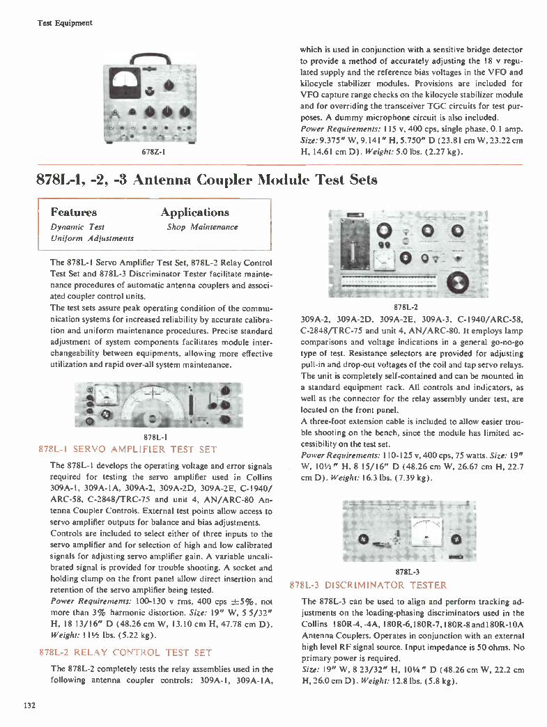
Test Equipment
irsamiN
•
678Z-1 'my UMW
which is used in conjunction with a sensitive bridge detector
to provide a method of accurately adjusting the 18 y regu-
lated supply and the reference bias voltages in the VFO and
kilocycle stabilizer modules. Provisions are included for
VFO capture range checks on the kilocycle stabilizer module
and for overriding the transceiver TGC circuits for test pur-
poses. A dummy microphone circuit is also included.
Power Requirements: 115 v, 400 cps, single phase, 0.1 amp.
Size: 9.375" W, 9.141" H, 5.750" D (23.81 cm W, 23.22 cm
H, 14.61 cm D). Weight: 5.0 lbs. (2.27 kg).
878L-1, -2, -3 Antenna Coupler Module Test Sets
Features Applications Dynamic Test Shop Maintenance
Uniform Adjustments
The 878L-1 Servo Amplifier Test Set, 878L-2 Relay Control
Test Set and 878L-3 Discriminator Tester facilitate mainte-
nance procedures of automatic antenna couplers and associ-ated coupler control units.
The test sets assure peak operating condition of the commu-
nication systems for increased reliability by accurate calibra-
tion and uniform maintenance procedures. Precise standard
adjustment of system components facilitates module inter-
changeability between equipments, allowing more effective
utilization and rapid over-all system maintenance.
878L-1
878L-I SERVO AMPLIFIER TEST SET
The 878L-1 develops the operating voltage and error signals
required for testing the servo amplifier used in Collins
309A-1, 309A-1A, 309A-2, 309A-2D, 309A-2E, C-1940/
ARC-58, C-2848/TRC-75 and unit 4, AN/ARC-80 An-
tenna Coupler Controls. External test points allow access to
servo amplifier outputs for balance and bias adjustments.
Controls are included to select either of three inputs to the
servo amplifier and for selection of high and low calibrated
signals for adjusting servo amplifier gain. A variable uncali-brated signal is provided for trouble shooting. A socket and
holding clamp on the front panel allow direct insertion and
retention of the servo amplifier being tested.
Power Requirements: 100-130 y rms, 400 cps -1=5%, not
more than 3% harmonic distortion. Size: 19" W, 5 5/32"
H, 18 13/16" D (48.26 cm W, 13.10 cm H, 47.78 cm D).
Weight: 11 1/2 lbs. (5.22 kg).
878L-2 RELAY CONTROL TEST SET
The 878L-2 completely tests the relay assemblies used in the
following antenna coupler controls: 309A-1, 309A-1A,
878L-2
309A-2, 309A-2D, 309A-2E, 309A-3, C-l940/ARC-58,
C-2848fTRC-75 and unit 4, AN/ARC-80. It employs lamp
comparisons and voltage indications in a general go-no-go
type of test. Resistance selectors are provided for adjusting
pull-in and drop-out voltages of the coil and tap servo relays.
The unit is completely self-contained and can be mounted in
a standard equipment rack. All controls and indicators, as
well as the connector for the relay assembly under test, are
located on the front panel.
A three-foot extension cable is included to allow easier trou-
ble shooting on the bench, since the module has limited ac-
cessibility on the test set.
Power Requirements: 110-125 v, 400 cps, 75 watts. Size: 19"
W, 101/2 " H, 8 15/16" D (48.26 cm W, 26.67 cm H, 22.7
cm D). Weight: 16.3 lbs. (7.39 kg).
e 878L-3
878L-3 DISCRIMINATOR TESTER
_ t
0 1-4
mile+ '
The 878L-3 can be used to align and perform tracking ad-
justments on the loading-phasing discriminators used in the
Collins 180R-4, -4A, 180R-6,180R-7, 180R-8 and180R-10A
Antenna Couplers. Operates in conjunction with an external
high level RF signal source. Input impedance is 50 ohms. No
primary power is required.
Size: 19" W, 8 23/32" H, 101/4 " D (48.26 cm W, 22.2 cm
H, 26.0 cm D). Weight: 12.8 lbs. (5.8 kg).
132
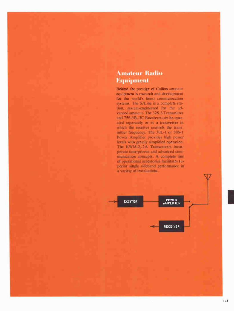
,%,.mateur Radio Equipment Behind the prestige of Collins amateur equipment is research and development for the world's finest communication systems. The S/Line is a complete sta-tion, system-engineered for the ad-vanced amateur. The 32S-3 Transmitter and 75S-3B,-3C Receivers can be oper-ated separately or as a transceiver in which the receiver controls the trans-mitter frequency. The 30L-1 or 30S-1 Power Amplifier provides high power levels with greatly simplified operation. The KWM-2,-2A Transceivers incor-porate time-proven and advanced com-munication concepts. A complete line of operational accessories facilitates su-perior single sideband performance in a variety of installations.
EXCITER POWER AMPLIFIER

Amateur Radio Equipment
30L-1 Linear Amplifier
Features Applications Automatic Load Control Fixed Station
RF Inverse Feedback Transportable
Silicon Rectifiers Shipboard
Self-contained Power Supply Mobile
Airborne
The 30L-1 Linear Amplifier provides 1000 watts PEP input
on SSB and CW on all bands. The linear amplifier is designed
to be driven by the Collins KWM-1 and KWM-2 Trans-
ceivers, as well as the 32S-3 Transmitter. Most other 70-100
watt CW/SSB exciters will also drive the linear.
The 30L-1 has a self-contained power supply with safety in-
terlock circuits for shorting the high voltage to ground if the
cover is removed. Automatic antenna switching from exciter
to amplifier or receive to transmit and instant warm-up are
also features of the 30L-1. The linear amplifier is completely
self-contained and designed for table top use. It is easily
transported in a CC-2 Carrying Case.
Specifications FREQUENCY RANGE: 3.4-30.0 mc, covering 80, 40, 20, 15 and
10 meter amateur bands. By retuning input circuit as neces-
sary, the following general coverage bands can be used:
Frequency Band
3.5 mc
7.0 mc
14.0 mc
21.0 mc
28.0 mc
MODE: SSB or CW.
Total Coverage
3.4-6.0 mc
6.0-9.5 mc
9.5-16.0 mc
16.0-22.0 mc
22.0-30.0 mc
TYPE OF SERVICE: Attended operation SSB continuous; CW
50% duty cycle.
POWER REQUIREMENTS: 115 V or 230 v, 50-60 cps; CW, key
closed, 1200 watts ac; SSB, no modulation, 300 watts ac;
SSB, speech modulated, 550 watts ac.
DRIVE POWER: 70-100 watts for full output.
PLATE POWER INPUT: 1000 watts PEP on SSB; 1000 watts on
CW on all bands.
POWER OUTPUT: Not less than 500 watts PEP into a 50 ohm
load on all bands.
HARMONIC AND OTHER SPURIOUS RADIATION: Second har-
monic —40 db; third order distortion —30 db at full power.
NOISE LEVEL: 40 db below one tone carrier.
AMBIENT TEMPERATURE: 0°-50° C.
AMBIENT HUMIDITY RANGE: 0%-90%.
OUTPUT IMPEDANCE: Variable. Normally 50 ohms unbal-
anced with not more than 2: I SWR on the amateur bands.
AUDIO COMPRESSION CHARACTERISTICS: ALC operates from
the RF input voltage and is factory set for proper input to
output voltage ratio.
ALTITUDE: 0-10,000 ft.
PROTECTIVE DEVICES: All removable panels interlocked. In-
put line fused 8 amps on each side.
SIZE: With feet, 143/4 " W, 73/4 " H, 133/4 " D (37.47 cm W,
19.69 cm H, 34.93 cm D).
W EIGHT: 38 lbs. (17.24 kg).
30S-1 Linear Amplifier
Features Applications RF Inverse Feedback Fixed Station
Instant Switching
Quick and Accurate Tuning
Automatic Load Control
The 30S-1 is a completely self-contained, linear amplifier.
Requiring 70-100 watts input (from 32S-3 or KWM-2), it
provides 1 kw PEP output on SSB, CW or RTTY.
An Eimac 4CX1000A is employed as a grounded grid linear
amplifier. The 30S-1 can be used on any frequency between
3.4 mc and 30.0 mc. A special comparator circuit allows
tune-up at low power.
All operating controls are easily accessible on the front panel,
allowing the linear amplifier to be tuned swiftly, surely and
easily. Power level can be switched instantly from the 100
watt power level of the associated S/Line transmitter to the
full output of the 30S-1 by the push of a button. The 30S-1
can also be tuned to frequencies outside the amateur bands.
Automatic load control voltage from the 30S-1 is fed back
to the transmitter to assure maximum talking power without
134
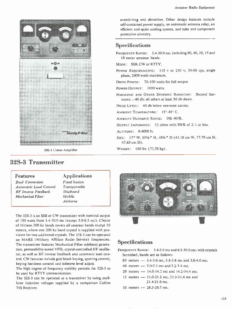
Amateur Radio Equipment
30S-1 Linear Amplifier
overdriving and distortion. Other design features include
self-contained power supply, an automatic antenna relay, an
efficient and quiet cooling system, and tube and component
protective circuitry.
Specifications FREQUENCY RANGE: 3.4-30.0 mc. including 80, 40, 20, 15 and
10 meter amateur bands.
MODE: SSB, CW or RTTY.
POWER REQUIREMENTS: 115 y or 230 1/, 50-60 cps, single
phase, 2000 watts maximum.
DRIVE POWER: 70-100 watts for full output.
POWER OUTPUT: 1000 watts.
HARMONIC AND OTHER SPURIOUS RADIATION: Second har-
monic —40 db; all others at least 50 db down.
NOISE LEVEL: 40 db below one-tone carrier.
AMBIENT TEMPERATURE: 15°-45° C.
AMBIENT HUMIDITY RANGE: 0% -90% .
OUTPUT IMPEDANCE: 52 ohms with SWR of 2:1 or less.
ALTITUDE: 0-6000 ft.
SIZE: 17" W , 305/8" H, 183/4 " D (43.18 cm W, 77.79 cm H,
47.63 cm D).
W EIGHT: 160 lbs. (72.58 kg).
32S-3 Transmitter
Features Dual Conversion
Automatic Load Control
RF Inverse Feedback
Mechanical Filter
Applications Fixed Station
Transportable
Shipboard
Mobile
Airborne
The 32S-3 is an SSB or CW transmitter with nominal output
of 100 watts from 3.4-30.0 mc (except 5.0-6.5 mc). Choice
of thirteen 200 kc bands covers all amateur bands except 10
meters, where one 200 kc band crystal is supplied with pro-
vision for two additional crystals. The 32S-3 can be operated
on MARS (Military Affiliate Radio Service) frequencies.
The transmitter features Mechanical Filter sideband genera-
tion, permeability-tuned VFO, crystal-controlled HF oscilla-
tor, as well as RF inverse feedback and automatic load con-
trol. CW features include grid block keying, spotting control,
keying hardness control and sidetone level adjust.
The high degree of frequency stability permits the 32S-3 to
be used for RTTY communication.
The 32S-3 can be operated as a transceiver by using oscil-
lator injection voltages supplied by a companion Collins
75S Receiver.
Specifications
FREQUENCY RANGE: 3.4-5.0 mc and 6.5-30.0 mc; with crystals
furnished, bands are as follows:
80 meters — 3.4-3.6 mc, 3.6-3.8 mc and 3.8-4.0 mc.
40 meters — 7.0-7.2 mc and 7.2-7.4 mc.
20 meters — 14.0-14.2 mc and 14.2-14.4 mc.
15 meters — 21.0-21.2 mc, 21.2-21.4 mc and
21.4-21.6 mc.
10 meters — 28.5-28.7 mc.
135

Amateur Radio Equipment
MODE: SSB (either sideband selectable) or CW.
TYPE OF SERVICE: SSB continuous; CW 50% duty cycle.
POWER REQUIREMENTS: 115 v, 50-60 cps using 516F-2 AC
Power Supply. Power can be delivered by an external supply
which must furnish 800 I/ dc at 220 ma for PA plates, 275 y
dc at 175 ma for PA screens and low voltage B+. Bias volt-
ages adjustable between —60 y and —80 y dc; 6.3 y ac at 7.7
amps or 6.0 v dc at 6.0 amps or 12.0-14.0 v dc at 3.0 amps or
24.0-28.0 NI dc at 1.5 amps. CW, key closed, 320 watts ac or
25 amps at 12 v. SSB, no modulation, 230 watts ac, 15 amps
at 12 v. SSB, speech, 255 watts ac, 20 amps at 12 v.
PLATE INPUT: 175 watts PEP on SSB; 160 watts on CW.
POWER OUTPUT: 100 watts PEP (nominal) into 50 ohms.
HARMONIC AND OTHER SPURIOUS RADIATION: Carrier suppres-
sion —50 db; unwanted sideband —50 db; oscillator feed-
through and/or mixer products —50 db. Second harmonic
—40 db. Third order distortion —30 db.
NOISE LEVEL: 40 db below one tone carrier.
AMBIENT TEMPERATURE: 0*-50° C.
AMBIENT HUMIDITY RANGE: 0%-90%.
ALTITUDE: 0- 10,000 ft.
PROTECTIVE DEVICES: Primary fuses provided in the compan-
ion 516F-2 ac power supply to be used with the equipment.
FREQUENCY STABILITY: Within 100 cps after warm-up.
CALIBRATION ACCURACY: 1 kc.
BACKLASH: Not more than 50 cps.
VISUAL DIAL ACCURACY: 200 cps on all bands.
OUTPUT IMPEDANCE: Variable 50 ohms nominal, capable of
matching up to 2:1 SWR.
CW SIDETONE: Provision for monitoring keying in receiver.
Sidetone level is adjustable.
KEYING CHARACTERISTICS: Grid block keying is free of chirp
and clicks. Modified break-in CW provided. Keyed carrier
used for CW keying. Envelope rise and decay time adjustable.
AUDIO INPUT: High impedance microphone or phone patch.
AUDIO FREQUENCY RESPONSE: 300-2400 cps -.±6 db.
AUDIO COMPRESSION CHARACTERISTICS: ALC operates on IF
and RF amplifier stages with 10 db of compression capability.
RF FEEDBACK: Approximately 10 db of RF feedback around
PA and driver for improved PA linearity.
SIZE: Transmitter with feet — 143/4 " W, 73/4 " H, 11 1/2 " D
(37.47 cm W, 19.69 cm H, 29.21 cm D).
WEIGHT: 16 lbs. (7.26 kg).
75S-3B, -3C Receivers
Features Rejection Tuning
Variable BFO
Optional Mechanical Filters
Zener Regulated Oscillators
Applications Fixed Station
Transportable
Shipboard
Mobile
Airborne
The 75S-3B,-3C provide SSB, CW and AM reception be-
tween 3.4 and 30.0 mc (except 5.0-6.5 mc) by selection of
the appropriate HF heterodyning crystals. Crystals furnished
cover HF amateur bands except the 10 meter band, where one crystal is supplied plus provision for two more.
Features incorporated in the 75S-3B,-3C include dual con-
version with a crystal-controlled first heterodyning oscilla-
tor; bandpass first IF; stable, permeability-tuned VFO; RF
amplifier designed to minimize cross-modulation products;
2.1 kc Mechanical Filter; excellent AGC characteristics; both
product and diode detector; rejection notch filter; manual
and crystal-controlled BFO, and AGC time constant control.
The advanced design of the 75S-3B,-3C includes the use of
silicon diodes in lieu of conventional high vacuum rectifier;
and the choice of two degrees of CW selectivity with optional
plug-in filters (also optional Mechanical Filters for AM).
Provision for obtaining power from a dc power supply is also made.
The 75S-3C is an extended frequency version of the 75S-3B
which includes an additional crystal board located beneath
the chassis. In this board is placed the standard complement
of amateur band crystals normally received with the equip-
ment. The upper board can be used for up to 14 additional
crystals. This permits ease of operating for MARS (Military
Affiliate Radio Service) and other military and commercial
applications. A front panel switch allows switching between
the two crystal boards.
A conventional RTTY converter and printer can be used
with the receiver. Fine tuning for this mode is provided by
the variable BFO adjustment.
The 75S-3B,-3C are compatible with Collins 32S-3 Trans-
mitter and 312B-4 Station Control to make a completely in-
136

Amateur Radio Equipment
tegrated amateur radio station. They are capable of supply-
ing oscillator injection voltages to the companion 32S-3
Transmitter. No auxiliary coupling units or wiring changes
are necessary. The two units are patched together with six
cables. A switch on the panel of the 32S-3 allows the choice
of either transceive or separate VFO operation.
The 75S-3B,-3C can also be conveniently used with other
transmitters including Collins' KWS-1, as well as with the
KWM- 1 or KWM-2 Transceivers. Muting is also provided
by the 32S-3 and KWM-2,-2A.
Specifications FREQUENCY RANGE: 3.4-5.0 mc and 6.5-30.0 mc; with crystals
furnished, bands are as follows:
80 meters — 3.4-3.6 mc, 3.6-3.8 mc and 3.8-4.0 mc.
40 meters — 7.0-7.2 mc and 7.2-7.4 mc.
20 meters — 14.0-14.2 mc and 14.2-14.4 mc.
WWV — 14.8-15.0 mc.
15 meters — 21.0-21.2 mc, 21.2-21.4 mc and
21.4-21.6 mc.
10 meters — 28.5-28.7 mc.
MODE: Selectable SSB, CW or AM.
POWER REQUIREMENTS: 115 v, 50-60 cps; approximately 85
watts. Power can be provided by an external supply which
delivers 185 y dc at 125 ma and —62 y dc at 5 ma. Filament
power can be ac or dc as follows: 6-7 y at 5.5 amps, 12-14
vat 2.75 amps, or 24-28 vat 1.4 amps.
HARMONIC AND OTHER SPURIOUS RESPONSE: Image rejection
better than 50 db. Internal spurious signals below 1 uy
equivalent antenna input.
AUDIO NOISE LEVEL: Not less than 40 db below 1 watt.
AMBIENT TEMPERATURE: 0*-50 ° C.
AMBIENT HUMIDITY RANGE: 0% -90%.
ALTITUDE: 0-10,000 ft.
CALIBRATOR: 100 kc crystal.
FREQUENCY STABILITY: Within 100 cps after warm-up.
CALIBRATION ACCURACY: I kc.
BACKLASH: Not more than 50 cps.
VISUAL DIAL ACCURACY: 200 cps on all bands.
SENSITIVITY: 0.5 uy for 10 db signal-plus-to-noise-to-noise
ratio in SSB mode.
SELECTIVITY: SSB — 2.1 kc at 6 db down; 4.2 kc at 60 db
down. AM — 5 kc at 6 db down; 25 kc at 60 db down.
OPTIONAL FILTERS: 200 cps, 500 cps, 800 cps, 1.5 kc for CW
and RTTY. 3.1 kc, 4.0 kc and 6.0 kc for AM.
Q MULTIPLIER: Rejection notch depth 50 db nominal, 40 db
minimum.
VARIABLE BFO: Tunes 452-458 kc.
AUTOMATIC GAIN CONTROL: AGC threshold — 1.5-3.0 try;
1.5 uy nominal. Selectable AGC time constant, Fast, Slow
and Off. Attack time is 0.8 milliseconds in both Fast and
Slow. Fast release time is 300 milliseconds. Slow release time
is 600 milliseconds.
AUDIO OUTPUT LEVEL: 1.0 watt at AGC threshold. 3.0 watts
maxim urn.
ANTENNA INPUT: 50 ohms.
AUDIO OUTPUT CIRCUITS: 500 ohms ±20% and 4 ohms
± 20% . Panel jack is on divider off of 500 ohm winding.
AU DIO DISTORTION: Not more than 10% at 1 watt.
MUTING: By opening an external ground on mute terminal.
SIZE: Receiver with feet — 143/4 " W, 73/4 " H, 12 1/2 " D
(37.47 cm W, 19.69 cm H, 31.75 cm D).
WEIGHT: 20 lbs. (9.07 kg).
KW M-2, -2A 175 W att TransceiN ers
Features Automatic Load Control
Inverse RF Feedback
Permeability-Tuned
Oscillator
Easy-to-Read Dial
Applications Fixed Station
Transportable
Shipboard
Mobile
Airborne
The KWM-2 and KWM-2A are compact HF single sideband
transceivers. The equipments have been used in rugged field
and air operations with combat units of United States and al-
lied military forces. The KWM-2 provides fourteen 200 kc
bands between 3.4 mc and 30.0 mc. The KWM-2A has a sec-
ond crystal board for selecting frequencies outside the ama-
teur bands. These additional 14 crystals provide ease of op-
KWM-2A Transceiver
eration for MARS (Military Affiliate Radio Service) and
other military and commercial applications. A front panel
switch permits switching between the two crystal boards.
The plate power input of the KWM-2,-2A is 175 watts PEP
137
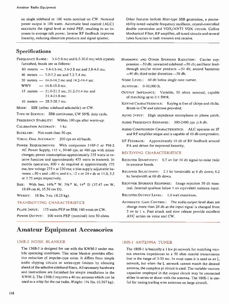
Amateur Radio Equipment
on single sideband or 160 watts nominal on CW. Nominal
power output is 100 watts. Automatic load control (ALC)
maintains the signal level at rated PEP, resulting in an in-
crease in average talk power. Inverse RF feedback improves
linearity, reducing distortion products and signal splatter.
Other features include filter-type SSB generation, a perme-
ability-tuned variable frequency oscillator, crystal-controlled
double conversion and VOX/ANTI VOX circuits. Collins
Mechanical Filter, RF amplifier, all tuned circuits and several
tubes function in both transmit and receive.
Specifications FREQUENCY RANGE: 3.4-5.0 mc and 6.5-30.0 mc; with crystals
furnished, bands are as follows:
80 meters — 3.4-3.6 mc, 3.6-3.8 mc and 3.8-4.0 mc.
40 meters — 7.0-7.2 mc and 7.2-7.4 mc.
20 meters — 14.0-14.2 mc and 14.2-14.4 mc.
WWV — 14.8-15.0 mc.
15 meters — 21.0-21.2 mc, 21.2-21.4 mc and
21.4-21.6 mc.
10 meters — 28.5-28.7 mc.
MODE: SSB (either sideband selectable) or CW.
TYPE OF SERVICE: SSB continuous; CW 50% duty cycle.
FREQUENCY STABILITY: Within 100 cps after warm-up.
CALIBRATION ACCURACY: 1 kc.
BACKLASH: Not more than 50 cps.
VISUAL DIAL ACCURACY: 200 cps on all bands.
POWER REQUIREMENTS: With companion 516F-2 or PM-2
AC Power Supply, 115 v, 50-60 cps, or 400 cps with minor
changes; power consumption approximately 235 watts in re-
ceive function and approximately 475 watts in transmit. In
mobile operation, 800 y dc required at approximately 175
ma; low voltage 275 y at 230 ma; a bias supply adjustable be-
tween —50 v and —80 v; and 6 v, 12 v or 24 v dc at 11.0, 5.5
or 2.75 amps respectively.
SIZE: With feet, 143/4" W. 73/4" H, 14" D (37.47 cm W,
19.69 cm H, 35.56 cm D).
WEIGHT: 18 lbs. 3 oz. (8.25 kg).
TRANSMITTING CHARACTERISTICS
PLATE INPUT: 175 watts PEP on SSB; 160 watts on CW.
POWER OUTPUT: 100 watts PEP (nominal) into 50 ohms.
HARMONIC AND OTHER SPURIOUS RADIATION: Carrier Sup-
pression —50 db; unwanted sideband —50 db; oscillator feed-
through and/or mixer products —50 db; second harmonic
—40 db; third order distortion —30 db.
Noise LEVEL: 40 db below single tone carrier.
ALTITUDE: 0-10,000 ft.
OUTPUT IMPEDANCE: Variable, 50 ohms nominal, capable
of matching up to 2:1 SWR.
KEYING CHARACTERISTICS: Keying is free of chirps and clicks.
Break-in CW and sidetone provided.
AUDIO INPUT: High impedance microphone or phone patch.
AUDIO FREQUENCY RESPONSE: 300-2400 cps ±6 db.
AUDIO COMPRESSION CHARACTERISTICS: ALC operates on IF
and RF amplifier stages and is capable of 10 db compression.
RF FEEDBACK: Approximately 10 db of RF feedback around
PA and driver for improved linearity.
RECEIVING CHARACTERISTICS
RECEIVER SENSITIVITY: 0.5 UV for 10 db signal-to-noise ratio
in amateur bands.
RECEIVER SELECTIVITY: 2.1 kc bandwidth at 6 db down; 4.2
kc bandwidth at 60 db down.
RECEIVER SPURIOUS RESPONSE: Image rejection 50 db nom-
inal. Internal spurious below 1 uy equivalent antenna input.
RECEIVER OUTPUT LEVEL: 1.0 Watt maximum.
AUTOMATIC GAIN CONTROL: The audio output level does not
change more than 20 db as the input signal is changed from
5 uy to 1 v. Fast attack and slow release provide excellent
AVC action on voice and CW.
Amateur Equipment Accessories
136B-2 NOISE BLANKER
The 136B-2 is designed for use with the KWM-2 under mo-
bile operating conditions. This noise blanker provides effec-
tive reduction of impulse-type noise. It differs from simple
audio clipping circuits or series-type limiters by silencing
ahead of the selective sideband filters. All necessary hardware
and instructions are furnished for simple installation in the
KWM-2. The I 36B-2 requires a 40 mc antenna which can be
used as a whip for the car radio. Weight: 11/4 lbs. (0.567 kg).
180S-1 ANTENNA TUNER
The 180S-1 is basically a 1 kw pi network for matching vari-
ous antenna impedances to a 50 ohm coaxial transmission
line in the range of 3-30 mc. In most cases it is used as an L
network, but when the L network cannot match the desired
antenna, the complete pi circuit is used. The variable vacuum
capacitor employed in the output circuit may be connected
either in series or shunt with the antenna. The 180S-1 is use-
ful for tuning trailing wire antennas on large aircraft.
138
Amateur Radio Equipment
302C-3 DIRECTIONAL WATTMETER
The 302C-3 is valuable for checking the antenna system. It
measures forward and reflected RF power. Two scales are
provided: 0-200 watts and 0-2000 watts accommodating
both high and low power transmitters. The 302C-3 is con-
tained in two units: the coupler for connecting into a 50 ohm
transmission line and the meter panel which is styled to
match the S/Line.
312B-3 SPEAKER
The 3I2B-3 contains a 5" x 7" (12.7 cm x 17.78 cm) speak-
er and connecting cable and is styled to match the S/Line
and KWM-2. Size: 10" W, 73/4 " H, 8" D (25.4 cm W, 19.69
cm H, 20.32 cm D). Weight: 4 lbs. (1.81 kg).
312B-4 SPEAKER CONSOLE
The 312B-4 integrates the 75S-3, 32S-3, 30S-I and acces-
sories into an operating system. The KWM-2 and 30S-1 can
also be integrated into an operating system by the 3I2B-4. A
speaker, RF directional wattmeter with 200 and 2000 watt
scales, and a phone patch are included in the console. Size:
10" W, 73/4 " H, 12 1/4 " D (25.4 cm W, 19.69 cm H, 31.12
cm D). Weight: 81/2 lbs. (3.86 kg).
312B-5 VFO CONSOLE
Designed for use with the KWM-2 in fixed station operation,
the 3I2B-5 provides limited separation of receive and trans-
mit frequencies, phone patching facilities and a directional
wattmeter. It includes a 5" x 7" permanent magnetic speak-
er. The PTO control selector can be set as follows: ( I)
Receive KWM-2, Transmit 312B-5; (2) Transceive KWM-2;
(3) Transceive 3I2B-5. Other control functions are Voice
Operated, Receive Only, Transmit Only, Phone Patch On-
Off, and Station Mute. Cables are furnished for connections
to the KWM-2. Size: 10" W,73/4 " H, 12 1/4 " D (25.4 cm W,
19.69 cm H, 31.12 cm D). Weight: 81/2 lbs. (3.86 kg).
351D-2 MOBILE MOUNT
The 35 ID-2 provides secure mounting for the KWM-2 in
most automobiles. Cantilever arms fold out of the way when
the KWM-2 is removed. The connector at the right end is the
power plug; the connector at the left end can be used for con-
trol of antennas having band switching circuitry. Cables 20
feet in length are attached to each plug.
351E MOUNTING PLATES
The 35 I E can be used to secure the S/Line or KWM-2 equip-
ments to bench or table in shipboard, airborne or vehicular
installations. The 351E- I will accommodate either the 75S-
36,-3C Receiver or the 32S-3 Transmitter: the 351E-2 will
mount either the 5I6F-2 Power Supply or the 3I2B-4 Station
Control: the 351E-3 will mount the 312B-3 Speaker. The
351E-4 has two snap-in clamps for secure installation of the
KWM-2. The equipment can be easily unclamped for re-
moval without the use of tools. The unit is removed by pulling
forward and lifting from the mounting plates.
351R RACK MOUNTING ADAPTERS
The 351R-I is a matching gray rack panel for mounting the
75S-3B,-3C, 32S-3, KWM-2, 30L-I, 62S-1 or 51S-1. The
351R-2 Rack Adapter is a panel for mounting the S/Line and
KWM-2 accessories. The 5I6F-2, 3I2B-4 and 312B-5 can be
mounted in the 351 R-2. Both adapters are 83/4 " H and
13 13/16" D ( 22.23 cm H and 33.5 cm D) behind the front
panel. A supporting shelf holds the unit securely. Mounting
hardware is furnished with each rack mount.
440E-1 CABLE KIT
The 440E-1 is similar to the cable which is supplied with the
Collins 351 D-2 Mobile Mount. This cable can be used to
connect the KWM-2 with the MP-1 or 516E-2 Power Supply
when the mobile mount is not used.
440E-1 CABLE
The 440E- 1 Cable is five feet in length and can be used to
connect either the S/Line or the KWM-2 to the 5I6F-2 Pow-
er Supply, allowing the 30S-1 to be placed a greater distance
from other units of the S/Line and permitting greater flexi-
bility of fixed station installations.
516F-2 AC POWER SUPPLY
The 5 I 6F-2 can be used with the 32S-3 and KWM-2. sup-
plying all voltages for them; 115 v. 50-60 cps. 400 cps with
minor change. Size: 10" W, 7-3/4 " H. 12" D ( 25.4 cm W,
19.69 cm H. 30.48 cm D). Weight: 28 lbs. (12.7 kg).
CC-2 CARRYING CASE
The CC-2 is designed to hold the components of a portable
Collins SSB or CW station. The KWM-2 plus the PM-2
Power Supply. the KWM-2 alone, the 30L- 1 or the 51S-1
can be transported in the case. The CC-2 is adapted from the
Samsonite Silhouette and includes a shock-resistant interior
for the equipment. Weight: 9.5 lbs. (4.31 kg) empty.
CC-3 CARRYING CASE
The CC-3 is a specially built case for accessory components
of a portable Collins SSB or CW station. The CC-3 has the
same styling features as the CC-2. A molded interior allows
the CC-3 to accommodate a 312B-5 (or 312B-4) Station
Control Console, a 516E-2 (or MP-1) Power Supply, a TD-1
Dipole Antenna, as well as a supply of spare tubes and fuses.
Weight: 10 lbs. (4.54 kg) empty.
CP-1 CRYSTAL PACKET
The CP-I contains a set of crystal grippers and all the crystals
for operation of the S/Line receiver, S/Line transmitter or
the KWM-2,-2A throughout the complete operating range.
The crystals not supplied are those for the range of 5.0 to 6.6
mc and those which are already provided with the equip-
ment. The packet is of a waterproof plastic material contain-
ing a pouch for each crystal and one for the grippers. Each
pouch is marked with appropriate band information and
crystal frequency. The complete packet can be fastened into
the CC-2 Carrying Case.
139
Amateur Radio Equipment
DL-1 DUMMY LOAD
The DL-1 is a 100 watt resistive load which can be used for
various tuning functions without putting the transmitter on
the air. The DL-1 can be switched in and out of the circuit by
a front panel switch or can be remotely controlled by the ad-
dition of another switch in the operating position. This unit
reduces tune-up and testing QRM and requires no additional
connecting or disconnecting of wires prior to operation.
Weight: 2 lbs. (1.3 kg).
MM-1 MOBILE MICROPHONE
The Collins MM-1 is a pressure-operated dynamic micro-
phone designed to fit your hand comfortably. This mike is
engineered for maximum voice response, and its die cast
case is finished in brushed satin chrome. With its mounting
button on the front, the MM-1 slips easily into a dashboard
bracket supplied with the mike. When the MM- l is removed
from the dashboard bracket, the microphone is in position
for instant transmission. A five-foot length of Koiled Kord
with mike plug supplied with the 22 ounce microphone. The
MM-1 has a frequency response from 200-10,000 cycles per
second and has an output level of —48 db.
MM-2 MICROPHONE
The Collins MM-2 includes a high impedance reluctance mi-
crophone and single earphone which can be used in either a
fixed station installation or with a mobile unit. The MM-2
has a frequency response from 100-7,000 cycles per second
and an output level of —50 db. In mobile use, the ear-piece
and microphone unit permit the driver to operate his car with
both hands while carrying out radio voice communication.
Although it weighs only 31/2 ounces ( 0.099 kg), the Collins
MM-2 is built to withstand the strenuous demands of daily
mobile operation. Its microphone boom has a 360° adjust-
ment making it possible to angle the mike to the best pickup
position. The MM-2 Microphone has a magnetic stray field
shield to exclude unwanted noises. For optimum reception of
signals, an adjustable tone arm in the MM-2 pipes sound di-
rectly into the operator's right or left ear, but does not cover
the ear as conventional earphones do. The MM-2 comes
equipped with both mike and phone plugs.
MP- l MOBILE POWER SUPPLY
The MP-1 converts a 12 volt automobile, aircraft or boat
battery to the voltages required for the KWM-1, KWM-2 or
KWM-2A. The MP-1 includes a high voltage supply for the
transmitter PA, bias, and a low voltage supply for the ampli-
fier. Size: 53/4 " W, 33/4 " H, 11" D (14.61 cm W, 9.53 cm H,
27.94 cm D). Weight: 71/2 lbs. (3.4 kg).
PM-2 PORTABLE POWER SUPPLY
The PM-2 is a lightweight, limited duty cycle power supply
providing voltages needed for the KWM-2. The PM-2 quick-
ly slides into place and connects to the rear of the KWM-2,
ready to operate in minutes from either 115 y ac or 220 y ac
at 50-400 cps as a complete portable SSB or CW station. Both
transceiver and power supply can be packed in the light-
weight CC-2 Carrying Case for portability. A small auxiliary
speaker is included in the PM-2 for emergency use. Size:
143/4 " W, 73/4 " H, 4" D (37.47 cm W, 19.69 cm H, 10.16
cm D). Weight: 13.5 lbs. (6.12 kg).
SM-1 DESK TOP MICROPHONE
Collins SM-1 is a high impedance, nonmetallic dynamic mike
with a frequency response from 100-3500 cycles per second.
It has an output level of —53 db. Finished in brushed satin
chrome, this compact microphone is equipped with a rubber
isolated stand and a five-foot length of Koiled Kord.
SM-2 MICROPHONE
Collins SM-2 is a slender, gray and chrome desk top unit
which blends perfectly with Collins other station equipment.
The SM-2 is omnidirectional and provides excellent trans-
mission for the amateur operator. The frequency response of
the SM-2, 200-3,000 cycles, matches that of the S/Line and
KWM-2. The SM-2 has an output level of —53 db and is
equipped with a five-foot length of Koiled Kord and plug. It
is mounted on a rubber isolated stand. A swivel permits a
60° swing for position adjustment.
TD-1 DIPOLE ANTENNA
The TD-1 is designed for use when portability and operation
on different frequencies are primary considerations. The
molded plastic housing holds two steel tapes calibrated in me-
ters, decimeters and centimeters. These tapes can be extended
to the required length for a given frequency and locked in
place. A permanent frequency-to-meters conversion chart is
attached to the antenna housing. Each end of the tape is at-
tached to a length of nylon line which acts as an insulator and
a means for securing the antenna to structures of suitable
height and positioning. A directional wattmeter should be
used for initial tune-up to insure the proper frequency setting.
140

Index, Glossary, Reference Informa • n e e °vim Pages c ..e .n in
by Collins type number, an index by equipment function and a cross index of applicable military nomenclature. Included also are tables, charts and graphs showing useful basic reference information.
141

Tables, Charts, Graphs
Finding Power and Voltage/Current when Decibels are known
Voltage Power Voltage Power Voltage Power Voltage Power
Ratio Ratio -db+ Ratio Ratio Ratio Ratio -db+ Ratio Ratio
1.0000 1.0000 o 1.000 1.000 .5623 .3162 5.0 1.778 3.162
.9886 .9772 .1 1.012 1.023 .5559 .3090 5.1 1.799 3.236
.9772 .9550 .2 1.023 1.047 .5495 .3020 5.2 1.820 3.311
.9661 .9333 .3 1.035 1.072 .5433 .2951 5.3 1.841 3.388
.9550 .9120 .4 1.047 1.096 .5370 .2884 5.4 1.862 3.467
.9441 .8913 .5 1.059 1.122 .5309 .2818 5.5 1.884 3.548
.9333 .8710 .6 1.072 1.148 .5248 .2754 5.6 1.905 3.631
.9226 .8511 .7 1.084 1.175 .5188 .2692 5.7 1.928 3.715
.9120 .8318 .e 1.096 1.202 .5129 .2630 5.8 1.950 3.802
.9016 .8128 .9 1.109 1.230 .5070 .2570 5.9 1.972 3.890
.8913 .7943 1.0 1.122 1.259 .5012 .2512 6.0 1.995 3.981
.8810 .7762 1.1 1.135 1.288 .4955 .2455 6.1 2.018 4.074
.8710 .7586 1.2 1.148 1.318 .4898 .2399 6.2 2.042 4.169
.8610 .7413 1.3 1.161 1.349 .4842 .2344 6.3 2.065 4.266
.8511 .7244 1.4 1.175 1.380 .4786 .2291 6.4 2.089 4.365
.8414 .7079 1.5 1.189 1.413 .4732 .2239 6.5 2.113 4.467
.8318 .6918 1.6 1.202 1.445 .4677 .2188 6.6 2.138 4.571
.8222 .6761 1.7 1.216 1.479 .4624 .2138 6.7 2.163 4.677
.8128 .6607 1.8 1.230 1.514 .4571 .2089 6.8 2.188 4.786
.8035 .6457 1.9 1.245 1.549 .4519 .2042 6.9 2.213 4.898
.7943 .6310 2.0 1.259 1.585 .4467 .1995 7.0 2.239 5.012
.7852 .6166 2.1 1.274 1.622 .4416 .1950 7.1 2.265 5.129
.7762 .6026 2.2 1.288 1.660 .4365 .1905 7.2 2.291 5.248
.7674 .5888 2.3 1.303 1.698 .4315 .1862 7.3 2.317 5.370
.7586 .5754 2.4 1.318 1.738 .4266 .1820 7.4 2.344 5.495
.7499 .5623 2.5 1.334 1.778 .4217 .1778 7.5 2.371 5.623
.7413 .5495 2.6 1.349 1.820 .4169 .1738 7.6 2.399 5.754
.7328 .5370 2.7 1.365 1.862 .4121 .1698 7.7 2.427 5.888
.7244 .5248 2.8 1.380 1.905 .4074 .1660 7.8 2.455 6.026
.7161 .5129 2.9 1.396 1.950 .4027 .1622 7.9 2.483 6.166
.7079 .5012 3.0 1.413 1.995 .3981 .1585 8.0 2.512 6.310
.6998 .4898 3.1 1.429 2.042 .3936 .1549 8.1 2.541 6.457
.6918 .4786 3.2 1.445 2.089 .3890 .1514 8.2 2.570 6.607
.6839 .4677 3.3 1.462 2.138 .3846 .1479 8.3 2.600 6.761
.6761 .4571 3.4 1.479 2.188 .3802 .1445 8.4 2.630 6.918
.6683 .4467 3.5 1.496 2.239 .3758 .1413 8.5 2.661 7.079
.6607 .4365 3.6 1.514 2.291 .3715 .1380 8.6 2.692 7.244
.6531 .4266 3.7 1.531 2.344 .3673 .1349 8.7 2.723 7.413
.6457 .4169 3.8 1.549 2.399 .3631 .1318 8.8 2.754 7.586
.6383 .4074 3.9 1.567 2.455 .3589 .1288 8.9 2.786 7.762
.6310 .3981 4.0 1.585 2.512 .3548 .1259 9.0 2.818 7.943
.6237 .3890 4.1 1.603 2.570 .3508 .1230 9.1 2.851 8.128
.6166 .3802 4.2 1.622 2.630 .3467 .1202 9.2 2.884 8.318
.6095 .3715 4.3 1.641 2.692 .3428 .1175 9.3 2.917 8.511
.6026 .3631 4.4 1.660 2.754 .3388 .1148 9.4 2.951 8.710
.5957 .3548 4.5 1.679 2.818 .3350 .1122 9.5 2.985 8.913
.5888 .3467 4.6 1.698 2.884 .3311 .1096 9.6 3.020 9.120
.5821 .3388 4.7 1.718 2.951 .3273 .1072 9.7 3.055 9.333
.5754 .3311 4.8 1.738 3.020 .3236 .1047 9.8 3.090 9.550
.5689 .3236 4.9 1.758 3.090 .3199 .1023 9.9 3.126 9.772
142

Tables, Charts, Graphs
Finding Power and Voltage/Current when Decibels are known
Voltage Power Voltage Power Voltage Power Voltage Power
Ratio Ratio - d b + Ratio Ratio Ratio Ratio -db+ Ratio Ratio
.3612 .1000 10.0 3.162 10.000 .1778 .03162 15.0 5.623 31.62
.3126 .09772 10.1 3.199 10.23 .1758 .03090 15.1 5.689 32.36
.3090 .09550 10.2 3.236 10.47 .1738 .03020 15.2 5.754 33.11
.3055 .09333 10.3 3.273 10.72 .1718 .02951 15.3 5.821 33.88
.3020 .09120 10.4 3.311 10.96 .1698 .02884 15.4 5.888 34.67
.2985 .08913 10.5 3.350 11.22 .1679 .02818 15.5 5.957 35.48
.2951 .08710 10.6 3.388 11.48 .1660 .02754 15.6 6.026 36.31
.2917 .08511 10.7 3.428 11.75 .1641 .02692 15.7 6.095 37.15
.2884 .08318 10.8 3.467 12.02 .1622 .02630 15.8 6.166 38.02
.2851 .08128 10.9 3.508 12.30 .1603 .02570 15.9 6.237 38.90
.2818 .07943 11.0 3.548 12.59 .1585 .02512 16.0 6.310 39.81
.2786 .07762 11.1 3.589 12.88 .1567 .02455 16.1 6.383 40.74
.2754 .07586 11.2 3.631 13.18 .1549 .02399 16.2 6.457 41.69
.2723 .07413 11.3 3.673 13.49 .1531 .02344 16.3 6.531 42.66
.2692 .07244 I 1.4 3.715 13.80 .1514 .02291 16.4 6.607 43.65
.2661 .07079 11.5 3.758 14.13 .1496 .02239 16.5 6.683 44.67
.2630 .06918 11.6 3.802 14.45 .1479 .02188 16.6 6.761 45.71
.2600 .06761 11.7 3.846 14.79 .1462 .02138 16.7 6.839 46.77
.2570 .06607 I 1.8 3.890 15.14 .1445 .02089 16.8 6.918 47.86
.2541 .06457 I 1.9 3.936 15.49 .1429 .02042 16.9 6.998 48.98
.2512 .06310 12.0 3.981 15.85 .1413 .01995 17.0 7.079 50.12
.2483 .06166 12.1 4.027 16.22 .1396 .01950 17.1 7.161 51.29
.2455 .06026 12.2 4.074 16.60 .1380 .01905 17.2 7.244 52.48
.2427 .05888 12.3 4.121 16.98 .1365 .01862 17.3 7.328 53.70
.2399 .05754 12.4 4.169 17.38 .1349 .01820 17.4 7.413 54.95
.2371 .05623 12.5 4.217 17.78 .1334 .01778 17.5 7.499 56.23
.2344 .05495 12.6 4.266 18.20 .1318 .01738 17.6 7.586 57.54
.2317 .05370 12.7 4.315 18.62 .1303 .01698 17.7 7.674 58.88
.2291 .05248 12.8 4.365 19.05 .1288 .01660 17.8 7.762 60.26
.2265 .05129 12.9 4.416 19.50 .1274 .01622 17.9 7.852 61.66
.2239 .05012 13.0 4.467 19.95 .1259 .01585 18.0 7.943 63.10
.2213 .04898 13.1 4.519 20.42 .1245 .01549 18.1 8.035 64.57
.2188 .04786 13.2 4.571 20.89 .1230 .01514 18.2 8.128 66.07
.2163 .04677 13.3 4.624 21.38 .1216 .01479 18.3 8.222 67.61
.2138 .04571 13.4 4.677 21.88 .1202 .01445 18.4 8.318 69.18
.2113 .04467 13.5 4.732 22.39 .1189 .01413 18.5 8.414 70.79
.2089 .04365 13.6 4.786 22.91 .1175 .01380 18.6 8.511 72.44
.2065 .04266 13.7 4.842 23.44 .1161 .01349 18.7 8.610 74.13
.2042 .04169 13.8 4.898 23.99 .1148 .01318 18.8 8.710 75.86
.2018 .04074 13.9 4.955 24.55 .1135 .01288 18.9 8.811 77.62
.1995 .03981 14.0 '5.012 25.12 .1122 .01259 19.0 8.913 79.43
.1972 .03890 14.1 5.070 25.70 .1109 .01230 19.1 9.016 81.28
.1950 .03802 14.2 5.129 26.30 .1096 .01202 19.2 9.120 83.18
.1928 .03715 14.3 5.188 26.92 .1084 .01175 19.3 9.226 85.11
.1905 .03631 14.4 5.248 27.54 .1072 .01148 19.4 9.333 87.10
.1884 .03548 14.5 5.309 28.18 .1059 .01122 19.5 9.441 89.13
.1862 .03467 14.6 5.370 28.84 .1047 .01096 19.6 9.550 91.20
.1841 .03388 14.7 5.433 29.51 .1035 .01072 19.7 9.661 93.33
.1820 .03311 14.8 5.495 30.20 .1023 .01047 19.8 9.772 95.50
.1799 .03236 14.9 5.559 30.90 .1012 .01023 19.9 9.896 97.72
.1000 .01000 20.0 10.000 100.00
143

Tables, Charts, Graphs
Finding Decibels when Voltage/Current Ratio is known
Voltage Ratio .00 .01 .02 .03 .04 .05 .06 .07 .08 .09
1.0 .000 .086 .172 .257 .341 .424 .506 .588 .668 .749
1.1 .828 .906 .984 1.062 1.138 1.214 1.289 1.364 1.438 1.511
1.2 1.584 1.656 1.727 1.798 1.868 1.938 2.007 2.076 2.144 2.212
1.3 2.279 2.345 2.411 2.477 2.542 2.607 2.671 2.734 2.798 2.860
1.4 2.923 2.984 3.046 3.107 3.167 3.227 3.287 3.346 3.405 3.464
1.5 3.522 3.580 3.637 3.694 3.750 3.807 3.862 3.918 3.973 4.028
1.6 4.082 4.137 4.190 4.244 4.297 4.350 4.402 4.454 4.506 4.558
1.7 4.609 4.660 4.711 4.761 4.811 4.861 4.910 4.959 5.008 5.057
1.8 5.105 5.154 5.201 5.249 5.296 5.343 5.390 5.437 5.483 5.529
1.9 5.575 5.621 5.666 5.711 5.756 5.801 5.845 5.889 5.933 5.977
2.0
2.1
2.2
2.3
2.4
2.5
2.6
2.7
2.8
2.9
3.0
3.1
3.2
3.3
3.4
6.021
6.444
6.848
7.235
7.604
7.959
8.299
8.627
8.943
9.248
9.542
9.827
10.103
10.370
10.630
6.064
6.486
6.888
7.272
7.640
7.993
8.333
8.659
8.974
9.278
9.571
9.855
10.130
10.397
10.655
6.107
6.527
6.927
7.310
7.676
8.028
8.366
8.691
9.005
9.308
9.600
9.883
10.157
10.423
10.681
6.150
6.568
6.966
7.347
7.712
8.062
8.399
8.723
9.036
9.337
9.629
9.911
10.184
10.449
10.706
6.193
6.608
7.008
7.384
7.748
8.097
8.432
8.755
9.066
9.367
9.657
9.939
10.211
10.475
10.731
6.235
6.649
7.044
7.421
7.783
8.131
8.465
8.787
9.097
9.396
9.686
9.966
10.238
10.501
10.756
6.277
6.689
7.082
7.458
7.819
8.165
8.498
8.818
9.127
9.426
9.714
9.994
10.264
10.527
10.782
6.319
6.729
7.121
7.495
7.854
8.199
8.530
8.850
9.158
9.455
9.743
10.021
10.291
10.553
10.807
6.361
6.769
7.159
7.532
7.889
8.232
8.563
8.881
9.188
9.484
9.771
10.049
10.317
10.578
10.832
6.403
6.809
7.197
7.568
7.924
8.266
8.595
8.912
9.218
9.513
9.799
10.076
10.344
10.604
10.857
3.5 10.881 10.906 10.931 10.955 10.980 11.005 11.029 11.053 11.078 11.102
3.6 11.126 11.150 11.174 11.198 11.222 11.246 11.270 11.293 11.317 11.341
3.7 11.364 11.387 11.411 11.434 11.457 11.481 11.504 11.527 11.550 11.573
3.8 11.596 11.618 11.641 11.664 11.687 11.709 11.732 11.754 11.777 11.799
3.9 11.821 11.844 11.866 11.888 11.910 11.932 11.954 11.976 11.998 12.019
4.0
4.1
4.2
4.3
4.4
4.5
4.6
4.7
4.8
4.9
5.0
5.1
5.2
5.3
5.4
5.5
5.6
5.7
5.8
5.9
6.0
6.1
6.2
6.3
6.4
12.041
12.256
12.465
12.669
12.869
13.064
13.255
13.442
13.625
13.804
13.979
14.151
14.320
14.486
14.648
14.807
14.964
15.117
15.269
15.417
15.563
15.707
15.848
15.987
16.124
12.063
12.277
12.486
12.690
12.889
13.084
13.274
13.460
13.643
13.822
13.997
14.168
14.337
14.502
14.664
14.823
14.979
15.133
15.284
15.432
15.577
15.721
15.862
16.001
16.137
12.085
12.298
12.506
12.710
12.908
13.103
13.293
13.479
13.661
13.839
14.014
14.185
14.353
14.518
14.680
14.839
14.995
15.148
15.298
15.446
15.592
15.735
15.876
16.014
16.151
12.106
12.319
12.527
12.730
12.928
13.122
13.312
13.497
13.679
13.857
14.031
14.202
14.370
14.535
14.696
14.855
15.010
15.163
15.313
15.461
15.606
15.749
15.890
16.028
16.164
12.128
12.340
12.547
12.750
12.948
13.141
13.330
13.516
13.697
13.875
14.049
14.219
14.387
14.551
14.712
14.870
15.026
15.178
15.328
15.476
15.621
15.763
15.904
16.042
16.178
12.149
12.361
12.568
12.770
12.967
13.160
13.349
13.534
13.715
13.892
14.066
14.236
14.403
14.567
14.728
14.886
15.041
15.193
15.343
15.490
15.635
15.778
15.918
16.055
16.191
12.171
12.382
12.588
12.790
12.987
13.179
13.368
13.552
13.733
13.910
14.083
14.253
14.420
14.583
14.744
14.902
15.056
15.208
15.358
15.505
15.649
15.792
15.931
16.069
16.205
12.192
12.403
12.609
12.810
13.006
13.198
13.386
13.570
13.751
13.927
14.100
14.270
14.436
14.599
14.760
14.917
15.072
15.224
15.373
15.519
15.664
15.806
15.945
16.083
16.218
12.213
12.424
12.629
12.829
13.026
13.217
13.405
13.589
13.768
13.945
14.117
14.287
14.453
14.616
14.776
14.933
15.087
15.239
15.388
15.534
15.678
15.820
15.959
16.096
16.232
12.234
12.444
12.649
12.849
13.045
13.236
13.423
13.607
13.786
13.962
14.134
14.303
14.469
14.632
14.791
14.948
15.102
15.254
15.402
15.549
15.692
15.834
15.973
16.110
16.245
144
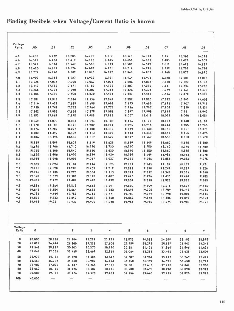
Tables, Charts, Graphs
Finding Decibels when Voltage/Current Ratio is known
Voltage Ratio .00 .01 .02 .03 .04 .05 .06 .07 .08 .09
6.5
6.6
6.7
6.8
6.9
7.0
7.1
7.2
7.3
7.4
7.5
7.6
7.7
7.8
7.9
8.0
8.1
8.2
8.3
8.4
8.5
8.6
8.7
8.8
8.9
9.0
9.1
9.2
9.3
9.4
9.5
9.6
9.7
9.8
9.9
16.258
16.391
16.521
16.650
16.777
16.902
17.025
17.147
17.266
17.385
17.501
17.616
17.730
17.842
17.953
18.062
18.170
18.276
18.382
18.486
18.588
18.690
18.790
18.890
18.988
19.085
19.181
19.276
19.370
19.463
19.554
19.645
19.735
19.825
19.913
16.272
16.404
16.534
16.663
16.790
16.914
17.037
17.159
17.278
17.396
17.513
17.628
17.741
17.853
17.964
18.073
18.180
18.287
18.392
18.496
18.599
18.700
18.800
18.900
18.998
19.094
19.190
19.285
19.379
19.472
19.564
19.654
19.744
19.833
19.921
16.285
16.417
16.547
16.676
16.802
16.927
17.050
17.171
17.290
17.408
17.524
17.639
17.752
17.864
17.975
18.083
18.191
18.297
18.402
18.506
18.609
18.710
18.810
18.909
19.007
19.104
19.200
19.295
19.388
19.481
19.573
19.664
19.753
19.842
19.930
16.298
16.430
16.560
16.688
16.815
16.939
17.062
17.183
17.302
17.420
17.536
17.650
17.764
17.875
17.985
18.094
18.202
18.308
18.413
18.517
18.619
18.720
18.820
18.919
19.017
19.114
19.209
19.304
19.398
19.490
19.582
19.673
19.762
19.851
19.939
16.312
16.443
16.573
16.701
16.827
16.951
17.074
17.195
17.314
17.431
17.547
17.662
17.775
17.886
17.996
18.105
18.212
18.319
18.423
18.527
18.629
18.730
18.830
18.929
19.027
19.123
19.219
19.313
19.407
19.499
19.591
19.682
19.771
19.860
19.948
16.325
16.456
16.586
16.714
16.840
16.964
17.086
17.207
17.326
17.443
17.559
17.673
17.786
17.897
18.007
18.116
18.223
18.329
18.434
18.537
18.639
18.740
18.840
18.939
19.036
19.133
19.228
19.323
19.416
19.509
19.600
19.691
19.780
19.869
19.956
16.338
16.469
16.599
16.726
16.852
16.976
17.098
17.219
17.338
17.455
17.570
17.685
17.797
17.908
18.018
18.127
18.234
18.340
18.444
18.547
18.649
18.750
18.850
18.949
19.046
19.143
19.238
19.332
19.426
19.518
19.609
19.700
19.789
19.878
19.965
16.351
16.483
16.612
16.739
16.865
16.988
17.110
17.231
17.349
17.466
17.582
17.696
17.808
17.919
18.029
18.137
18.244
18.350
18.455
18.558
18.660
18.760
18.860
18.958
19.056
19.152
19.247
19.342
19.435
19.527
19.618
19.709
19.798
19.886
19.974
16.365
16.496
16.625
16.752
16.877
17.001
17.122
17.243
17.361
17.478
17.593
17.707
17.820
17.931
18.040
18.148
18.255
18.361
18.465
18.568
18.670
18.770
18.870
18.968
19.066
19.162
19.257
19.351
19.444
19.536
19.627
19.718
19.807
19.895
19.983
16.378
16.509
16.637
16.764
16.890
17.013
17.135
17.255
17.373
17.490
17.605
17.719
17.831
17.942
18.051
18.159
18.266
18.371
18.475
18.578
18.680
18.780
18.880
18.978
19.075
19.171
19.226
19.360
19.453
19.545
19.636
19.726
19.816
19.904
19.991
Voltage Ratio O 1 2 3 4 5 6 7 e 9
10 20.000 20.828 21.584 22.279 22.923
20 26.021 26.444 26.848 27.235 27.604
30 29.542 29.827 30.103 30.370 30.630
40 32.041 32.256 32.465 32.669 32.869
50 33.979 34.151 34.320 34.486
60 35.563 35.707 35.848 35.987
70 36.902 37.025 37.147 37.266
80 38.062 38.170 38.276 38.382
90 39.085 39.181 39.276 39.370
100 40.000
34.648
36.124
37.385
38.486
39.463
23.522
27.959
30.881
33.064
34.807
36.258
37.501
38.588
39.554
24.082
28.299
31.126
33.255
34.964
36.391
37.616
38.690
39.645
24.609
28.627
31.364
33.442
35.117
36.521
37.730
38.790
39.735
25.105
28.943
31.596
33.625
35.269
36.650
37.842
38.890
39.825
25.575
29.248
31.821
33.804
35.417
36.777
37.953
38.988
39.913
145

Chart for converting current or power ratios to decibels,
,1,111. 1.1,1,1,1,1,1,1,11",11,1,L1L1,11:13,1ii 1
VOLTAGE- CURRENT OR POWER 111111111111Ï1111Ï111111Ï1111111111111111k11111 I 1 1 .11,111)111111.1%1111(11,11111111111I1111111,1111111111I111 i zr,1:1111,iiiiril II
v‘
DECIBELS
DECIBELS
III 1 11 11
VOLTAGE OR CURRENT
PI 1 ti11 111-1 1111111
POWER
VOLTAGE OR CURRENT
POWER
1 1
I 1 I 11_1 I 1131 11111 1111111111111t111111111111111111111111111111111111t111111111 111111111t11111111 1111I111 111111111 ni
43
VOLTAGE-CURRENT OR POWER 1 1 11111 -1-1-11 -n 1 1 1 11111111 1 1 11 11111 11111 1 1 1 111Il HUI 1 1 1 11111 111: 1 I 111111111 1
am °Ole ePui
btuq3 uo!saaAue) laqpau
stid
uip •s
puti
p Sa
lqE

Tables, Charts, Graphs
— 30 +20
Examples explaining the use of the decibel conversion chart
are as follows:
(1) Assume a voltage ratio of 2.4 to 1.2. This voltage ratio
in decibels is found by drawing a line from 1.2 on scale A to
2.4 on scale E passing through the decibel voltage scale C at
6 decibels. This can also be found on scales B, D and F; how-
ever, the decibel scale D is not expanded as much as the
decibel scale C and cannot be read as accurately.
(2) Assume a voltage ratio of 1200 to 1.2. This voltage ra-
tio in decibels is found by drawing a line from 1.2 on scale B
to 1200 on scale F passing through the decibel scale D at 60
decibels.
(3) Assume a power ratio of 580 to 320. This power ratio in
decibels is found by drawing a line from 3.2 on scale A to
5.8 on scale E (the ratio of 580 to 320 is the same as 5.8 to
3.2) passing through the decibel scale D at 2.6 decibels.
From the above examples it will be noted that the smaller
value of any ratio will always be located on scale A or B and
the larger value will always be located on the respective scale
E or F. Also, the decibels corresponding to ratios of less than
10 to 1 can be found on either set of scales; however, it is
preferable to use scales A, C and E as the decibel scale C is
expanded and can be read with greater accuracy.
O +50
—10 +40
_20 +30
7.)
Q> —40 +10
—50 0 0.001=10 -3
10 -8
DBM NS. W atts
DBM 10 LOOK, 0.001
001 01 1 10
10-7 10 -6 10 -5 10 -4
Power in Watts
Antennas, Towers and .NN ave Propagation
40
••• 30 C• ew
ew et, c
20
1.0
• • 10
Z..
O 10 11 12 13 14 15 16 17 18 1.9 2.0
\-oltage Standing Wave Ratio Increase in attenuation in line due to VSWR on line.
100
10-
147
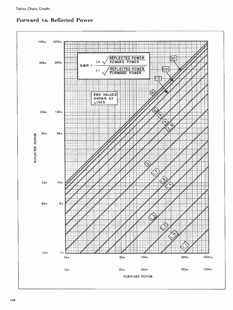
Tables,Charts,Graphs
Forward vs. Reflected Power
REFLECTED POWER
100kw 1000w
50kw 500w
10kw I 00w
5kw 50w
1 kw 10w
.5kw 5w
.1kw 1w
IMMIIIBMMI I •IIMB•11»M MMM ••••••MMI
,--......-- • ••••U
di:IMBUE CZ: 'MU MIMI MIII «MY Ma In .. IIMIIIIMIIMIUM111 mum' WM/ ill mum :::::;:::: Miligania Mal riniii Eli ill 11 il mmiiiiirai MIR :ma inaiifil
lazumunniZBUIRRIIIIIIIIIIreOrA. «EBB IMIumilitiel"'"Iluiliduire/ .mr.d ffral 50
ienIMELNA E 4r.áZ0ân Pilqw "ere. reig mini Manilla o__I ,41.43 AC:eill
11:8:18)1191EleffeedrilirlI MP FA
SWR
MEE
REFLECTED POWER FOWARD POWER
, /REFLECTED POWER FORWARD POWER
10 zi». u. "Amur r.=.===EMEMI Ie.===MMICEEPIIMMIIIIIEktàhmedriAtegar FAH
---- ---- =::
EEET-..21-liiiIMIIIIIIIiirec.::::715P2eigie-Orintri 4110 --- 72
m - :9 — — — lc: mu :::: CZ= «,!,11.0p, r rillIVAIMIdi Ki pi agai.... ........
VALUES SHOWN AT Einniliiiiiiilkeser warnammuumre . Iràditaird .....».«
eammulm iiil MIMI IIIIMBI de/I.M 4 ie 4 a I »Ail Adir A ...............A. r or
........., LINES a MIMMINIMMIr.e.ar.
111111111111111111111 -it 11117111111 IIIIIMMIFIr4e4 111111»3111111 ZUMMIIIIIIIIPIV.et A 4,
anc=::::: raminu:::::::::aralopy.rAnwiesirialumouranumno ram :::::.;::: um ::::: ::::: IMIZZWZOICUIrdenellenommonsr.mm ....mi....UM linalà.nn puma invArimemnivaalr..wwwm.tmlizamm ..... NM Ma inn n11111132•11 Mil EMI MI F., OF 11/MnallIr4 ‘111 ., egBUIF.1 IMMZEMMUilill MEI mum PM Mn Mr, r.ill !A riMr4. imisr.dniii., ell...MP à1 MIMI IMIMMIIIIIIIIIIIIummumumnelMo.dmi/Mlinlinilre /fflmmwrilluzzillIze
le-E2MFM-Manrri0: 5 1WiiiiirAho-.ialfrialargig. . E.33eleherediMallrojAreolFilEEZien,.ilinVallillii211 MMIIIM1•111131•1111 13131», RI .... dià MI.IMI, Aj'.t...11111' ...1131111à•
Z:ZOBBMIIIMET,FOra UM: ammo r 40, 4 Aigumig AIM »ram ganiumrau IF'. OM MI WAIF MM 4 or. „di
Ammar dill ninnr ALUMINIUM Mieldill
gill p r.1 muumuu. um me« wed MI. I» I/ .11MMIIIIIIMI, .111•11.1.
ifflii"Làeenri r e e rfregad r KilgrIlÉiMtiegr'reeelilee: EM511111EN
iMnieardigii r iargigr a ridatillnil or- riominpzion:-.Parejetraf.ilillEffilliff111110.511111-1 drale AnileArdiluiprAgrektunimuntairiamm
MAU 5111M 2 11::"::11/111*Iiiitilddidallii A/ row go nuareendillIndrifullpun op -4,-.=-4auralureurdmirduc rainzmanumv.realum:::r.‘::::::::: UTAIIIIIIIIIIPIMMINPIIIIIIM 11111111,211111111FAIL ., MIMI ; tilii:VaZ O I FrAMPAMErtraiiianig a IMMIIIMMUMMIIRAIIIIVAIpli allerlinlIWAINFAMIIE11111 Frdi162111111111%11111M111111111111E1111 WP.21111211051111Ed111111COMFAIM11111/111111111E1118 VARIgillpe.11101i1118ffleaRilrialleillUS a rgaiiiitinriiIIMÉrredriifiiii-EMPligi r-ataigimr iilmisiv nimeeirma:razEmi ......, •- ..........1-• -.3
-eatIMMIP.21 Antiiie prule.fewlEEEIElb ..... ,IMMIIII MN II. M.. ,
mr MMMMM amp? •••• •MM MIMI MI: •
amiu: crepe -.:... Am« nun W iiiimeigr-Are: • - M rl. miz: :: r. 81 .... an i inn um nr dim ou InW I MOM MEW II r eribiLigee::: .4'41» MIII Mini IMP AM NM Ili Inl--M--liel r- MUM MU,' .r.dla In 811181n WM. • In MI
InntAn Mal W.IMMInir IMIIIM an nzw.Ennannnurammont:seau 133-1 Mil ITÀ »Lin IMIPUBMUMFAIIIinilir 'WA _ •MaZIPAIIIMIIIIMMIUUMnilr'..1113111111$0111•4•1111M1 IBMIMUIFd11111111U1I WM IIWA111111MUMW40111111111 IMIIIIIIIIV AP:o1111111111111111 MIIIIMPAIIIIIIIIP:1111111M11111111111g1IIIIIIMIIFí BUMP 11111111111111à JP:111MM II II MIIIIIIIIIVAIIIIIIIIMIIIMPIIIIIIIIIIVAIIIIIIIIIMMI4MIIIIWAIIIIIIIIIIIIIIIMIIIIMI lull
I Ow
kw
50w 100w
5kw 10kw
FORWARD POWER
500w 1000w

Tables, Charts, Graphs
Reactance Chart
.neuctoncet reectance Xl. or XC
- 2000-
- 1000
- 500
200 V
50
lO-
- 5
2
=- I
:= 0.5 •
0.05
- 0.02 - 20
=- 0.01
0.005
5 - 0.002
0.001 -- 1000
2 1 - 500
- 0.5
- 0.2
- 0.1
- 0.05
- 0.02
- 0.01
- 0.005
- 0.002
tr. - 10 0
5
- 2
=- I
0.5
- 0.2
- 0.1
- 0.05
- 0.02
•
capocitanœ C
- 0.02
- 0.05
- 0.1
- 0.2
- 0.5
1
- 2
Z-- 5 4.
-lo 4.
20 •
- 50
100
- 200
- 500 1000 -
- 0.001-
- 0.002
-- 0.005
0.01
- 0.02
• - 0.05
»- 0.1
- 0.2
0.5
-
- 1
5
- 10
- 20
- 50
- 100
200
= 500 1000
0.002
0.0051
- 0.01 0.02 -e
frequency f
- 1000-
- 500
•00
- 500
- 200
ISO
- 10 0
- 50
- 40
10
20
- IS
- 5
- 4
- 3
inductance'. modem. XL or XC capacitance C frequency f
9Ir 9r - 2000
1000
- 100
- 50
- 20
- 10
- 2
.2 t
0.5
0.2
0.1
0.05
0.02
- 0.01
0.005
0.002
10-- - 5
- 2
=.- 1
- 0.5
- 0.05 - •
0.02
0.01
- 0.005
- 0.002
0.001 1000
- SOO
200
'= 100
50
20
- 10
- 5
1
- 0.5
0.2
r 0.,
0.05
- 0.02
- 0.01-
0 00002
0.00005
- 0.0001
0.0002
0.0005
0.001
- 0.002 V
- 0.005
-0.01
0.02
0.05
0.1
-0.2 4.. 4.
=. 0.5
- I
- t
Z- 5 •
- 10
- 20
- 50
- 100
- 200
- 500
100gg11- •- 0.002
0.005
- 0.01
0.02
- 0.05
0.1
- 0.2
- 1000-
500
- 400
- 300 •
200
- ISO
- 50
•0
30
- 20
15
5
- 4
3
2
- 1.5
a
Decimal Equivalents of Fractions
1/32 .03125 9/32 28125 17/32 53125 25/32 78125 1/16 .0625 5/16 .3125 9/16 5625 13/16 8125
3/32 09375 11/32 .34375 19/32 59375 27/32 84375 1/8 .125 3/8 .375 5/8 .625 7/8 875
5/32 .15625 13/32 40625 21/32 .65625 29/32 .90625 3/16 .1875 7/16 .4375 11/16 .6875 15/16 9375
7/32 .21875 15/32 .46875 23/32 .71875 31/32 96875 1/4 _______ _._..25 1/2 5 3/4 .75 1 1.0
149
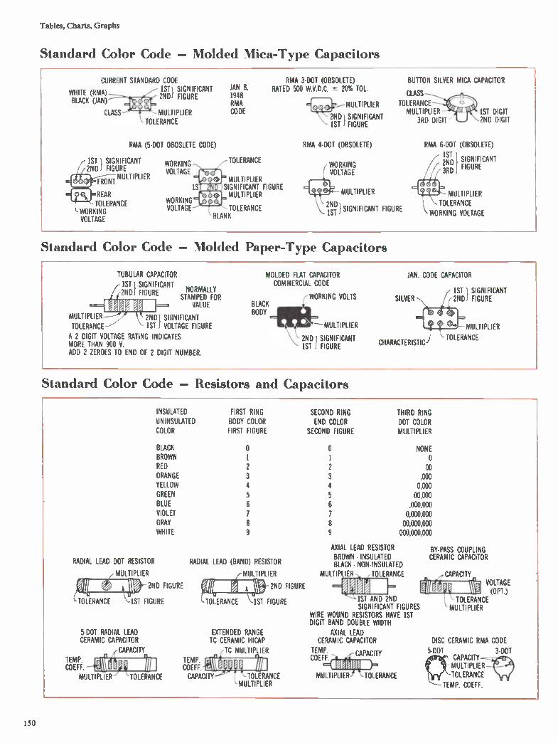
Tables, Charts, Graphs
Standard Color Code — Molded Mica-Type Capacitors
CURRENT STANDARD CODE 1ST} SIGNIFICANT WHITE (RMA) 2NDI FIGURE BLACK (JAN) CLASS MULTIPLIER TOLERANCE RMA (5-DOT OBOSLETE CODE) ( 1ST 1 SIGNIFICANT // 2NDI FIGURE MULTIPLIER
,,=REAR TOLERANCE WORKING VOLTAGE
WORKING VOLTAGE WORKING VOLTAGE
JAN 8, 1948 RMA CODE
/- TOLERANCE MULTIPLIER 1S SIGNIFICANT FIGURE MULTIPLIER TOLERANCE BLANK
RMA 3-DOT (OBSOLETE) RATED 500 W.V.D.C. 20% TOL. MULTIPLIER 2ND i SIGNIFICANT 1ST 1 FIGURE RMA 4-DOT (OBSOLETE)
BUTTON SILVER MICA CAPACITOR CLASS TOLERANCE MULTIPLIER - 1ST DIGIT 3RD DIGIT 2ND DIGIT
7 (11TKPtI 1'1 41= ef•— MULTIPLIER _2NDI SIGNIFICANT FIGURE 1ST
RMA 6-DOT (OBSOLETE) 1ST 2NDiï6 1 SIGNIFICANT FIGURE
e MULTIPLIER TOLERANCE WORKING VOLTAGE Standard Color Code — Molded Paper-Type Capacitors
TUBULAR CAPACITOR ( 1ST 1 SIGNIFICANT ,2ND, FIGURE NORMALLY STAMPED FOR VALUE MULTIPLIER 2ND SIGNIFICANT TOLERANCE 1ST , VOLTAGE FIGURE A 2 DIGIT VOLTAGE RATING INDICATES MORE THAN 900 V ADD 2 ZEROES TO END OF 2 DIGIT NUMBER.
MOLDED FLAT CAPACITOR COMMERCIAL CODE r WORKING VOLTS BLACK BODY =M1-MULTIPLIER 2ND 1 SIGNIFICANT 1ST 1 FIGURE
JAN. CODE CAPACITOR SILVER 1ST 1 SIGNIFICANT
/ ç 2ND! FIGURE MULTIPLIER
CHARACTERISTIC) TOLERANCE
Standard Color Code — Resistors and Capacitors
INSULATED FIRST RING UN INSULATED BODY COLOR COLOR FIRST FIGURE BLACK BROWN 1 RED 2 ORANGE 3 YELLOW 4 GREEN 5 BLUE 6 VIOLET 7 GRAY 8 WHITE 9
RADIAL LEAD DOT RESISTOR MULTIPLIER 2ND FIGURE TOLERANCE 1ST FIGURE 5-DOT RADIAL LEAD CERAMIC CAPACITOR (CAPACITY
711 TEMP. COEFF. ell d J)14 MULTIPLIER 'TOLERANCE
RADIAL LEAD (BAND) RESISTOR MULTIPLIER VA 2ND FIGURE TOLERANCE 1ST FIGURE
TEMP. COEFF EXTENDED RANGE TC CERAMIC HICAP TC MULTIPLIER
SECOND RING END COLOR SECOND FIGURE O 2 3 4 5 6 7 8 9
THIRD RING DOT COLOR MULTIPLIER NONE o
oo ,000
0,000 00,000
,000,000 0,000,000
00,000,000 000,000,000 AXIAL LEAD RESISTOR BROWN INSULATED BLACK NON•INSULATED MULTIPLIER TOLERANCE
1ST AND 2ND SIGNIFICANT FIGURES WIRE WOUND RESISTORS HAVE 1ST DIGIT BAND DOUBLE WIDTH AXIAL LEAD CERAMIC CAPACITOR TEMP CAPACITY COEFF CAPACITY TOLERANCE MULTIPLIER TOLERANCE MULTIPLIER
BY-PASS COUPLING CERAMIC CAPACITOR ,CAPACITY r
lb VOLTAGE TOLERANCE (OPT.) MULTIPLIER DISC CERAMIC RMA CODE 5-DOT 3-DOT CAPACITY-MULTIPLIER TOLERANCE COEFF.
150

Tables, Charts, Graphs
Radiation Angle %emus Great Circle Distance Curves MMIgilMM=iE
4000
9500
3000
2500
2000
..................f...................71,............................... cl::ipporiimiminti 111::: ma:m_81:1111101.11111.dininuldninouin lumen MMM I lllll 11111111 I I
ilejnigginnilielin 1 I ! 1.11111 11 I I I
re_lMIMIMMEMb:1111111.1 Ill IIIIIIIIIIIII! 1.11111111 1 .M. I. MablitillialinliiI9111.1 II I RI I I la II li I
M•MallelMMIII I 1111111111111111M1 1111111111111111111 MR.11111
MINIMUM liZillalliiill 110 MIIIIIIIMMIUHROMVIIII 11 MIIIMMIIIMMIII1101111111‘ 11 II MIIIIMINZMIZIIMIIIIIIII:.°0 111111. MIIMMIIIIIIIIIIIIIIIIIIIIIIh 4-'91111111 IIIIIIiir.5111BMIMIIIIIIIIIIi.4111 11111
I I iillillilliiiilliii iiiiiiiiIrliiiiIII III IIIIIMMINZZEINII11111111111 ill Ill pill 1111111111111111111
11 MI.MBIM.1111111.11 Ill ills III IIIIII 1111111111111111111 II IIIIIMMIIIIIIIiil Inzu11 Ili lull III 111111111 I 111111111111111111
iiiiiiiiiin111111111 111111111111111111 imanzunutlin I, 3 igliill
Mininiiiireg Mil I I Iiijill6. iii......iiiGein i li libi IL 11»111111121111•1111filik " 11111111111111 II I MMIM BR M E I II ii II i il 111111111 111811 II 111111111
Malli Mg MI a Mil I li 11031.111III II IIIIIIIII ........................ T. b inigairnelliiiii Ill II III I iiiiiIIIIIIIIIIIIIIIIIII MIIIIImillaril I. Iii III ifilifillili IIIIIIIIIIII
i Hirsh I I I I ! II i !m@iminicagium imp plum Map 11111111 II 11111 IIIIIIMIIMMIIIIIMIIIih, 11 Mall 110111 loll i 111•MMIII1111111301 I I 111111i i11110111111111111111111111111
alaiiM111111•1111111111I. lull 11111111IIIIIi I I II i 1 MMMMI111§io MIT 11111111 IIIIII 11111111 II 11111 allM111111111111111 linunsimpiniii.upli iji n i Innings Mug II l 1111s11111111111 Ilillii1111111111 MIIIIBM11:911.11 II 111:1111:411111111111e1111 11,1 ill 1 11 1 • MMMIIIIMII Illni II 111111111111IIII 1 1111111111111111111 iiinallIZI111113111. amp Innuniaartabluailui gnananalli I 11111111111111BM I 111111111111111111
1500
1000
500
MMMIIIIMIIMee II I III IlallIll 111081011110i1 ill 3113111.111.171. 1111111111 IIIIII1 II I 1111111111111111111
NIII1111111111111111311fih. III i III awl§ nappy' siop il minnulna in upwn nummonninunnun in11111111•11111111111111111111 I 111 1111 illuom ponfidnampi i i MIIIIIIMIERIIII lit Illillilll WWII 1111111111111111111 IMIIIIIIIMIIIIIMIIMMIII I 1101111 1111111lii. 11111m011101111. II ••MMIMIMBMURIal 11§111111111111Mill 1111111111111111111 MIZ111111111111121111111111 I I 11111101111111111111:111111111b91111111101 M.MBRZBIRMIIIMII1111111111111111118811 1 1111111111111111111 MMMUMMUIIIIIIIIIIil II 51111111,11ilinlilleillill111011011111; niuMMIMMIIIIMIIIIr 111111111111111111111 I 1111111111111111111 1111111111MIZZMMIIMII I I I 1111111111101•11111 I 110111111140111111111:11•11111111 IIIIIIIIIII II 111111111111111•111111 1111111111111111111 MMIIII11311111111M11111 I 1111111111111111111 i 111110111111111011011101111MMIZIIIIMMIIIII 11 111111111111111•11 I 1111111111111111111 IIIIMMBRIMIIMIIII I I 11111111111111111:11 111.111Z1111111111ililiiIIIIIIIIIIIIIIIIIIIMMUI1 1 11111111111111MM I 111111111111111111 IIIIIBIZIMBMIZEIMMII 11111111111111111,11111 111;11111111110111MIMMIIIMIIIMIIIIIII 1£11111111111111111111 1 11111I111111111111 MMIMBIIIIIIIMIIIIIIIII I 11111111111111M 11 loin innanununnamommungunnipionfimpunmumunnumuu wilalnaZaMMUMINIIIIIIIIIIIIIIIIIIIIIII 'WI illilliI MIIIIIIIIIIIIIIIIMMIIIIII 111111111111111M 111111: III I IiIII 111111akImM11111111M111111 1.111111i111011111111 111111111111111111
11111111101111MBZWIRIIIIIIIIIIIIIIiIIIIIIIIIIIMI 111111111111111111
IMINIIIIIIIIIIIIMMIIII I I 1111111111111•111 4 11111121111111111i. 1111111111MMIMIIIIIIIIMMI I 111111111111111111111 111111111111111111 Biiir.IIIIIIMM ‘11IIIII I 11111111111111MII 11111111:11111111110111IMUMNIIIIIIMIIIIIIIII111111111111MIII I 111111111111111111 MIMIllni:511 11 11111111111111inlil 1111111111:11111111111:1111111101MMIIIMIIIIIIIIIIIIIIIIIIIIIIIIIIIIII1111111111111111111
IIIIIMMIMMIIIMMIk I 1111111 IIIIIIIIIII 1111111111110111111IIMMM11111 111111111111111 I 11111 11111111111M 1111111111111111111 usgurannuirnuniniqumunningionainminnuairunannunuonnaup unnannas
nnnangganni. monnal gamin lillillilli 11É1111111111‘113WWMIWZMIIIIIIIIIIiil 111111111U11 I 1111111111111111111 IMMMIMMIIIIIIIIIIIIIIIM111111111111111111 I I 11111111111 111111111111MIMMallliaMIIIIII11111110111111111111 11111111111111111u IIIIIMZEMIfill1111 I 1111i111111111111•11 I 1111 1111111 lillili lille1111‘111;111111111.1 I II 1111111011111111111 I 1111111111111111111 MZIIIIMIIIIIIMBIIII I I 111111lialllilimillIli 011111 I 111 111111111111Mn/Mellill 111111111L11111111111 1111111111111111111
I
:::::::IIIICIIIIIIIIIIIMMIIMIMMIMM illIMEEVILleallgîNMIIIIIMIIMPUIMIIIIIIIIIMIIIIIIIII munannagninnuanumnumusinionnunganumunnninnwingammilinuTpannumunnuanunu nanangnaniniumingunannionniu millininun immazammiggeilluir hommomminurnimil munammummlimunpilimpoirml i 1 annumningainnaliannanini gqa. III II, um munkganguagithia nap gamminanumunimp
muifirm MIRM9M11 1111114M11111 II 111111111111111H1111111111111111
IIIMMINIIIMBMMUIMI 4111111111111M H1111111 I I III 11111111113MMOIMMOUMO£11111111111 1111111111111111111111111111 IMMIMIIIIIMZUM11111111111111111111111118111101111111111118.1111111111111111101111C1W118811111111118111111111111111111111 MMBRZMMIIMIM 1111111111111111 SIMI 1181111111 Iiiillollillm1111.11111h111111CIUMIlliiIIIIIIIIIIICI I 111111111111111111 MIMIMIZZEIIMIll II 11111111111 11 HUI 11111111W 4:111111111111IMmalialKIMMII1g91,IIIIIIIIIIIMII 111111111111111111
I
railii::::11111111MIIIIMIIMMIIIIIMIMIIIIMMI:111115MIMMIIIMMIIIMMIIIIIIIII IIIMINBIIIIIIIIIIIIIIIIIIIIIIIIIIIIIII1111111 IIII 1111111111111111111fflMillumIIMM1111111agin111111Mill11111111111iiiiiiiii
iMMMIIIIIIMMIIIIill III III l 11111 I III I 1 li III 1111I1I 11111 11111Milalmila in. Illilig 01;11111E1 I 1011111111111111111 munnonnumusinin in ant I DI I iill III Mil 1111101111111•111 111p9 Illirli11111111111 1111111111111111111 I
1111 lannIIIIMIIIIIIIIIIIIIIIIIII111 MI al II I 1 Illin I uluuniinagn! Roma IL ilUIVIIIIIIII 114111111111111111 MmallillIIIIIMMIIIIIIIiiiiilil II II 11111111n 1 111•1111NulazIn ning b FiibMilliIII 111111111111111111 IIIIIIIIIIIIMMMMIIIIIIIIIIIIIIIIIIIIIII 111 I 11111 11111111 11111111 in•MbIllaarlIn 1:11‘11110111010111 I I 'W11111111111111 rirmillaMMIIIIIIIIiIiiliiill I Ill III II 11111 Illiil i IIIIIIMMMIle.! ii! I III.11i1.1111q1111 I agginfinimi
mil BASED ON IONOSPHERE 1111 I I i ll il ii I Hi II i 1 1111 I 111:Mal:i: 111 111 IIIIIIIMIIIIIII4MIMPIIIIM111411 i. mil VIRTUAL LAYER HE 1 GHT 1111 nu Bah 111 111111 IMIMM.B.MESZIGOi 111111111111111e1MNI111.111111111111
Ill MR E.LAYER 105 KM
F.LAYER 320 KM 111111111111111111111111111111111111111111111Elirilirilrillieliglillielli11 1"1111
BIM
Mill 11 11111 11 id 1111111111 11 11111 IMIUMBEIIIIIIMIIII jillillinhh11111111111 manannagniansannipuirrnuaniumummarnallignieranunau eunlitzioi¡maunE ninnanniannicany i 1 Ii a 1 Imp "npuliiinu ag!! mg alimairli:91 IlliperlI111111 MIZIIIIBB81111111111.111111 Illil li 1 1 I li HMI IIIIIIIIIIIIIIIM Buzz lulu Ili; I Illi 31111111 pelilik- I,Ic MIIIIIIMIMMBIIIIIIIIIIIIiill III ill I Ill 1111111111111111111111111111 MUM MINI I 11111 I iiil 1111141111101110.9W- ,di mumiamizzilmimilisiiiiiiiiiiiimlimi iiiiiiiiinimmimmummium MI I 1 11111111111111M111 11111111111111till: o
2 3 4 5 7 10
RADIATION ANGLE IN DEGREES
20 30 40 50 70 50
151

Tables, Charts, Graphs
Symbols and Prefixes
au alternating current al audio frequency AFC automatic frequency
control A M amplitude modulation amp ampere ASA American Standards
Association ASTM American Society for
Testing Materials AVC automatic volume control ave average
susceptance BCD binary-coded decimal • capacitance • Centigrade, degrees
Centigrade centimeter cash on delivery cycles per second continuous wave dissipation factor decibel decibel referred to one
milliwatt de direct current • voltage EIA Electronics Industries
Association electromotive force Fahrenheit, degrees
Fahrenheit farad frequency
fm frequency modulation free on board
• conductance gravitation constant gigacycles per second
g„, transconductance li henry h, forward current-transfer
ratio h, short-circuit input
impedance open-circuit output
admittance reverse voltage-transfer
ratio current International
Electrotechnical Commission
IEEE Institute of Electrical and Electronics Engineers
I F intermediate frequency in. inch IRE Institute of Radio
Engineers
cm COD cps cw D db dbm
emf
ISO International Standards Organization
kg kva kw
lab lb LC If log
ma max mbar MC' mh mil min mm mmho me Me MMe mv mw
SeC
nt5
oz
PF pl PH
pp ppm p-to-p prf
RC re rf RH rms rpm
sec sync
V — 1 kilo ( I 0') kilogram kilovolt ampere kilowatt inductance laboratory pound inductance-capacitance low frequency logarithm mass
meter; milli (10 -milliampere maximum millibar megacycles per second millihenry 0.001 inch minimum; minute millimeter millimho milliohm mego hm megamegohm millivolt milliwatt nano ( 10 -9) ; any
number nanosecond nanomho ounce parallel, as power factor picofarad hydrogen in
concentration push-pull; pages parts per million peak-to-peak pulse repetition
frequency quality factor resistance registered trademark resistance-capacitance referred to radio frequency relative humidity root-mean-square revolutions per minute series, as L. second synchronous,
synchronizing period temperature time
uhf
va vhf vif vol VS
X
Y
a
ultra-high frequency velocity volt voltampere very high frequency very low frequency volume versus watt reactance admittance impedance short-circuit forward
current-transfer ratio (common base)
short-circuit forward current-transfer ratio (common emitter)
reflection coefficient increment loss angle phase angle wavelength micro- ( 10 - 6) microampere microbar microfarad microhenry microsecond microvolt ohm mho angular velocity (2771)
Prefixes Orders of magnitude from 1012 to 10-18 are designated by the fol-lowing prefixes:
Prefix Order Symbol 1 012 tera T I 09 giga G 1 06 mega M I 03 kilo k 102 hecto h 10 deka da 10- i d deci i 0-2 c centi I 0-3 milli m 1 0-6 micro
nano I 0-9 n 10-12 pico p 10-15 femto f I 0-19 a atto
152

Military Nomenclature Cross Reference
Military Nomenclature
AN /ARM-73
AN /MRC-95
AN / PRC-38
AN /PRC-47
AN /SRA-22
AN /URC-32
C-1940 /ARC-58
C-3940 /ARC-94
C-4832 /TSW
C-6116 /TSC-15
C-6118 /FRC-93
CU-351 /AR
CU-523 /ARC-58
CU-737 /URC
CU-791 /URT
CU-991 /AR
CU-1169 /SRC-16
CU-1170 /SRC-16
F-871 /U
M-127 /FRC-93
MK-773
OA-1373 /FRC
OA-1448 /GRT
OA-2008 /FRR-53
PP-3702 /ARC-102
PP-3990 /FRC-93
R-1122/GR
R-1156/GR
RT-648 /ARC-94
RT-698 /ARC-102
RT-718 /FRC-93
Equipment
Test Harness
HF Communication System
HF-VHF Transceiver
HF Transceiver
HF Antenna Coupler
HF Transceiver
Coupler Control
Radio Set Control
Coupler Control
Frequency Control
Speaker Console
HF Antenna Coupler
HF Antenna Coupler
Line Flattener
Line Flattener
HF Antenna Coupler
HF Antenna Coupler
HF Antenna Coupler
Bandpass Filter
Microphone
Maintenance Kit
Frequency Standard
HF Power Amplifier
Frequency Standard
Power Inverter Mounting
Power Supply
Receiver
Receiver
HF Transceiver
HF Transceiver
HF Transceiver
Collins Type No.
678P-2
VC-102
618K-1
618U-1
180T-2
KWT-6-8
309A-2
714E-3
309A-2D
714Y-2
312B-4
180L-3A
180R-6
180U-2A
180Y-1
180L-2
490C-1
490C-2
635R-1
MM-1
678Y-3
40N-2
205J-1
40N-1
390J-2
PM-2
51S-1
51S-1F
618T-2
618T-3
KWM-2A
153

Collins Qualit and Reliabilit
Collins Radio Company's reputation for dependable products
is a result of the application of rigid, uncompromising standards
of excellence. Quality and reliability testing programs are car-
ried out by autonomous organizations whose responsibility
crosses boundaries of design, engineering and production.
The quality control programs ensure that Collins equipment and
systems perform according to predetermined specifications in
the manufacturing test facility, as well as in the intended opera-
tional environment. Collins' reliability engineers work with de-
velopment engineers to assure equipments and systems which
will provide long, useful life.
The programs begin with the preparation of specifications for
components and subsystems purchased from outside suppliers.
When the first engineering model of a new equipment is com-
pleted, the unit is subjected to stringent and detailed review by
a reliability committee composed of specialists trained to find
and correct possible troubles. Following this, a preproduction or
pilot line assembly operation provides manufacturing with an
opportunity to finalize production assembly techniques and se-
quences before initiation of the regular production schedule. Se-
lected Collins equipments are also proven in an operational en-
vironment in the company's experimental HF radio station lo-
cated in Cedar Rapids.
In manufacturing, each of the modules and subassemblies is
subjected to stringent inspection. Groups of modules are then
unitized and again given rigid examination as a subsystem.
Maintenance of required specifications is assured by use of
either standard test equipment, or as is true in many cases, test
equipment developed by Collins to fill a specific requirement.
Completed units, composed of modules and subsystems which
have already been thoroughly checked, are given highly critical
final tests. Here again the finest test devices known are employed.
The finished product must meet or exceed exacting specifica-
tions, and it must perform satisfactorily in actual operating con-
ditions. The final testing stage involves an operating or reliability
run. This is performed under the environmental conditions in
which the equipment will be used.
As a further quality audit, equipments are selected from finished
154
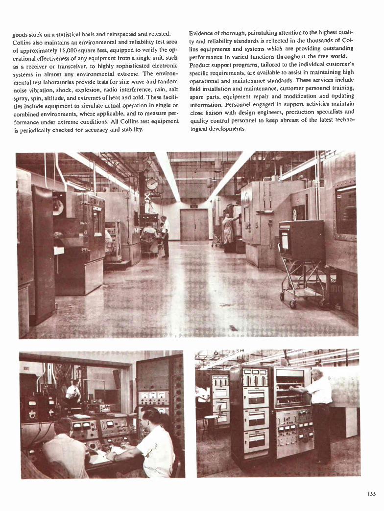
goods stock on a statistical basis and reinspected and retested.
Collins also maintains an environmental and reliability test area
of approximately 16,000 square feet, equipped to verify the op-
erational effectiveness of any equipment from a single unit, such
as a receiver or transceiver, to highly sophisticated electronic
systems in almost any environmental extreme. The environ-
mental test laboratories provide tests for sine wave and random
noise vibration, shock, explosion, radio interference, rain, salt
spray, spin, altitude, and extremes of heat and cold. These facili-
ties include equipment to simulate actual operation in single or
combined environments, where applicable, and to measure per-
formance under extreme conditions. All Collins test equipment
is periodically checked for accuracy and stability.
Evidence of thorough, painstaking attention to the highest quali-
ty and reliability standards is reflected in the thousands of Col-
lins equipments and systems which are providing outstanding
performance in varied functions throughout the free world.
Product support programs, tailored to the individual customer's
specific requirements, are available to assist in maintaining high
operational and maintenance standards. These services include
field installation and maintenance, customer personnel training,
spare parts, equipment repair and modification and updating information. Personnel engaged in support activities maintain
close liaison with design engineers, production specialists and
quality control personnel to keep abreast of the latest techno-
logical developments.
155
Index by Type Number
8U-1 Frequency Divider 82
30L-1 Linear Amplifier 134
30S-I Linear Amplifier 134, 135
32MS-I B 100 Watt Mobile Transceiver 3, 4, 39-41
32RS-1 100 Watt Transceiver 8, 9, 42, 43
32S-3 Transmitter 134-136
40K-I Oscillator 82
40N-I Frequency Standard 57, 58, 82
40N-2 Frequency Standard 82
48A-1SW Desk Set Control 40
48B-2SW Mobile Control 40
51S-I Communication Receiver 18-20
5 IS-IA Receiver 19
51S-IAF Receiver 19
51S-IF Receiver 18, 19
54M-I Frequency Comparator 82
75S Receiver 135
75S-3B Receiver 136, 137
75S-3C Receiver 136, 137
76F-1 Speaker 3, 5, 75, 76
136B-2 Noise Blanker 138
143A-I Azimuth Rotation Control 93
143A-IA Azimuth Rotation Control 93
152.1-1 Phone Patch 42, 43
156G-I Receiver Coupler 102, 103
I80L-2 Antenna Coupler 101
180L-3 Antenna Coupler 101
180L-3A Antenna Coupler 101
180R-4 Antenna Coupler 101, 101
180R-6 Antenna Coupler 7, 10, 102, 103
180R-6A Line Flattener 103
180R-7 Antenna Coupler 103
180R-12 Antenna Coupler 103, 104
180S-I Antenna Tuner 138
180T-2 Antenna Coupler 9, 16, 104, 105
180U-2 Line Flattener 105
180U-2A Line Flattener
180V-2 Antenna Coupler 4, 9, 43
180Y-1 Line Flattener 105, 106
184U-I0 RF Matrix Uniswitch 8, 106, 107
199Q-1 Cooling Blower 55
205.14 45 KW HF Power Amplifier
208U-3 3 KW HF Power Amplifier
208U-10 10 KW Power Amplifier
237B-I Rotatable-Unidirectional
8,
8, 14,
HF Antenna 93, 94, 99
237C-1 Unidirectional HF Antenna 94, 99
237C-2 Unidirectional HF Antenna 94, 99
237N-1C Unidirectional HF Antenna 95, 99
237N-2C Unidirectional HF Antenna 95, 99
302C-3 Directional Wattmeter 139
302E-2 Directional Wattmeter 42
309A-I Coupler Control 101, 102
309A-2 Coupler Control 102, 103
309A-2D Coupler Control 7, 10, 102, 103 309A-2E Coupler Control 103
309A-9 Coupler Control 103, 104
310V-1 Universal Radio Group Exciter ... 8, 14, 25-27, 87
312B-3 Speaker 139
312B-4 Speaker Console 139
312B-5 VFO Console 139
312C-1 Panel Mounted Speaker 19
312C-2 Panel Mounted Speaker 19
3I2C-3 Panel Mounted Speaker 19
3I3B-3 Cabinet Speaker 19
313J-/ Dial Pulse Control 8, 11, 83-85
313K-1 Allotter-Preset 8, 11, 83-85
313L-I Frequency Register 8, 11, 83-85
313Q-I Control Unit 83, 85
313V-I Control Unit 3, 5
313W- I Remote Control 41
350D-3 Mounting 101
351D-1 Mobile Mount 139
351E Mounting Plates 139
351E-1 Mounting Plate 139
35IE-.) Mounting Plate 139
351E-3 Mounting Plate 19, 139
351E-4 Mounting Plate 19, 139
351R-1 Rack Mount 19, 139
35 I R-1 Rack Mount 19, 139
399C-I External VFO Unit 139
399R-1 Teletypewriter Adapter 117-119
399S-I Time Base 117-119
426A-I Power Supply 82
426U-2 27.5 V DC Power Supply 11, 86
437C-1A Broadband Monopole Antenna 95, 96, 99
437C-2A Broadband Monopole Antenna 95, 96, 99
437C-3A Broadband Monopole Antenna ... 61, 95, 96, 99
437G-/A Broadband Dipole Antenna 96, 97, 99
105 437P-I Mobile Antenna 40
437R-I HF Helical Antenna 109
440E-1 Cable Kit 139
440F-1 Cable 139
452A- l Lightning Arrestor 101, 102
8, 28-31 476D-1 Distortion Analyzer-Monitor 130
14, 32, 33 478R-I Spectrum Analyzer 130, 131
34-36, 113 488A-I DC to AC Inverter 107
488A-2 DC to AC Inverter 108
490B-1 Automatic Antenna Coupler 3, 5, 108
490C-I Antenna Coupler 115
490C-2 Antenna Coupler 115
490T-1 Antenna Coupler 4, 109
499L-I Mounting Shelf 21, 22
499L-/ Mounting Shelf 26
499L-3 Mounting Shelf 46, 47
512B-2 HF Impedance Conversion Unit 109, 110
156
Index by Type Number
512D-1 HF Impedance Conversion Unit
5I6F-2 AC Power Supply 136, 138, 139
5 I 6H-1 Power Supply 45
548L-4 1 KW Power
Amplifier 4, 7, 8, 10, 11, 14, 37, 86
618T HF Transceiver 6, 7, 44, 45, 71, 102, 108
6I8T- I Transceiver 44, 45
6I8T-2 Transceiver 44, 45
6I8T-3 Transceiver 44, 45, 62, 75
618T HF Transceiver Test Sets 131, 132
6I8Z-4 RF Translator 10, 11, 87-90
635R-I HF Receiver Bandpass Filter 110, 1 II
635T-2 HF Receiver Bandpass Filter 111, 112
635V-I HF Receiver Filter 8, 10, 11, 14, 112
635W-I Harmonic Filter 113
637B-I A Transportable Rotatable HF Antenna 97, 99
637C-3 Transportable Broadband HF Antenna 97-99
637E-1 Transportable Unidirectional HF Antenna .. 98, 99
651F-I Universal Radio Group Receiver 14, 21-23, 87
671B-I Universal Radio Group
Receiver-Exciter 4, 7, 8, 46-48
678P-I Test Harness 131
678Y-I Maintenance Kit 131
678Z- l Function Test Set 131, 132
690D-I Load Coil 76
700B-2 Teletypewriter
Converter 4, 7, 16, 72, 75, 78, 80, 122, 123
700C-1 Teletypewriter Adapter Kit 13, 55, 123
714E-2 Control 7, 44, 45
714E-3 Control 45
714Y Control 83
714Y-1 Control Unit 4, 7, 90
714Y-2 Control Unit 4, 90
718F-1 HF Receiver-Transmitter 3, 5
718M-1 UHF Receiver-Transmitter 5, 78, 79
789R-1 IF Translator 10, 88-90
789T-I IF Translator 10, 11, 88-90
789X-1 IF Translator 88-90
878L-1 Servo Amplifier Test Set 132
8781-2 Relay Control Test Set 132
878L-3 Discriminator Tester 132
914B-2 Control Unit 11 I
9 I 4B-3 Control I 12
AM-3535 Amplifier-Control 50
AM-3536/URC RF Amplifier 50
AN/ARC-52X Radio Set 78-80
AN/ARC-80 Airborne HF Communication
System 6, 49, 50
AN/ARC-94 System 44, 45
AN/ARC-94 Test Sets 131
AN/ARC-IO2 System 44, 45
AN/ARC-102 Test Sets 131
110 AN/ARC-105 Airborne HF Communication
System 51, 52
AN/ARM-73 Portable Test Set 131
AN/GRA-6 Remote Control 3, 5, 75, 76, 78, 80
AN/MRC-95 Vehicular HF Communication
System 62, 63
AN/PRC-38 40 Watt SSB-FM Man Pack
Transceiver 12, 13, 53, 54
AN/PRC-47 100 Watt Man Pack HF
Transceiver 13, 55, 56
AN/SRA-22 Antenna Coupler 104, 105
AN/SRC-I6 Shipboard HF Communication
System 15, 64-66
AN/SRC-23 Shipboard HF Communication
System 15, 66
AN/TRC-115 Transportable HF Communication
System 66, 67
AN/TSC-38 Transportable HF Communication
System 10, 34, 68-70
AN/URC-32 HF Transceiver 8, 9, 14, 16, 57, 58
ANNA-1 Air Transportable HF Communication
System 10, 60, 61
AS-390 UHF Discone Antenna 5, 78, 80
AS-1321 Trailing Wire Antenna 50
AT-101 System 102
AT-101A System 102
AT-102 System 102
BB-451/U Battery 54
C-4368 Control Unit 50
C-4658/SRC-I6 Antenna Coupler Control 115
C-4958/ARC-I05 Control Unit 51, 52
C-4959/ARC-105 Control Unit 51, 52
CC-2 Carrying Case 19, 134, 139
CC-3 Carrying Case 139
CG-2755/ARC-105 RF Transmission Line 52
CF-1 Crystal Packet 139, 140
CU-737/URC Line Flattener 105
CU-791/URT Line Flattener 105, 106
CU-1094 Antenna Coupler 50
CU-1169/SRC- I 6 Antenna Coupler 66, 115
CU-1170/SRC-16 Antenna Coupler 66, 115
CU-1239/ARC-105 Antenna Coupler 51,52
DL-I Dummy Load 140
F-775 Interference Filter 50
F-776 Low Pass Filter 50
H33F/PT Handset 63, 67
H33G/PT Handset 56
H F-I0 I HF Communication System 44, 45
HF-IO2 HF Communication System 44, 45
HF-I03 HF Communication System 44, 45
HF-los Shipboard HF Communication System
HF-106 Shipboard HF Communication System
HF-107 Shipboard HF Communication System
16, 71, 72
16, 71, 72
16, 71, 72
157

Index by Function
HF-108 Shipboard HF Communication System .. 16, 71, 72
HF-I09 Shipboard HF Communication System .. 16, 71, 72
HS-1 Headset 19
ID-1066 Control-Indicator 50
KWM-1 Transceiver 134
KWM-2 175 Watt Transceiver 134, 137, 138
KWM-2A 175 Watt Transceiver 137, 138
M-151 Vehicle 62, 79, 80
M38A-1 Vehicle 77, 78
MK-773 Portable Test Set 131
MM-1 Mobile Microphone 140
MM-2 Microphone 140
MP-1 Mobile Power Supply 140
MT-2790 Antenna Coupler Mounting 50
MT-3094/ARC-I05 Mounting 52
MT-3095/ARC-I05 Mounting 52
MX-6066/ARC-105 Vacuum Capacitor 52
MX-6067/ARC-105 Feed Line Capacitor 52
MX-6068/ARC-105 Inerconnect Capacitor 52
0A-1448/GRT 45 KW HF Power Amplifier 28-31
PM-2 Portable Power Supply 138, 140
R-1122/GR Communication Receiver 18-20
R-I153/URC Receiver 50
R-1156/GR Communication Receiver 18, 19
RT-712/ARC-I05 Receiver-Transmitter 51, 52
S-14I Shelter 69
S-141A/G Shelter 60
S-I44( VG Shelter 66, 67, 73, 74
SM-1 Desk Top Microphone 140
SM-2 Microphone 140
Index by Function
Accessories
Air Transportable Communication Systems 10, 60, 61
Airborne Typical Systems 6, 7, 51, 52
Allotter-Preset 8, 11, 83-85
Amateur Radio Equipment 133-140
Amplifiers, Linear 134, 135
Anchor Kits
Antennas
Broadband Dipole 96, 97, 99
Broadband Monopole 61, 95, 96, 99
Dipole 140
Mobile 40
Rotatable-Unidirectional 93, 94, 99
Trailing Wire 6, 49, 50
Transportable Broadband 97-99
Transportable Rotatable 97, 99
Transportable Unidirectional 98, 99
Unidirectional 94, 95, 99
Antenna Couplers 4, 7, 9, 10, 16, 43, 50-52, 66, 100-115
SW-1020TA Automatic Switchboard 113, 114
SW-1030A Automatic Switchboard 113, 114
T-899/URC Transmitter 50
TCS-I 10-1 HF Communication Terminal 11, 73, 74
TD-I Dipole Antenna 140
TE-,02 Kineplex* Data Terminal 120-122, 127
TE-202E-3 Transmit Terminal 120-122
TE-,02F-6 Receive Terminal 120-122
TE-202G-6 Diversity Receive Terminal 120-122
TE-204A-2 Data Modem 117-120
TE-, 10 Modem 126
TE-2 10D-, Data Modem 125
TE-, I2 Digital Data Modem 124, 125
I2D Digital Data Communication Modem 124
TE-2 I6A-4 Adaptive Kineplexe Data
Communication Modern 126, 127
TE-216A-20 Adaptive Kineplex® Data Modem 127, 128
TE-216B-4 Data Transmitter 126, 127
TE-, 1 6B-20 Transmit Terminal 127, 128
TE-, I 6C-4 Data Receiver 127
TE-216C-20 Receive Terminal 127, 128
TE-, 1 6D-20 Diversity Receive Terminal 127, 128
TT4 Teletypewriter 63
TT-76/FG Keyboard 74
TT-98/FG Page Printer/Keyboard 74
VC-IO2 HF Communication System 3, 75, 76, 78-80
VC-I04 Vehicular HF-UHF Communication
System 3, 5, 77, 78
VC-106 Vehicular HF-UHF Communication
System 3, 5, 79, 80
Antenna Couplers and Accessories 100-115
Automatic Switchboards 113, 114
Azimuth Rotation Control 93
Bandpass Filters 110-112
Cabinets 91
Cable Kits
Carrying Cases 19, 134, 139
Charts, Graphs and Tables 142-152
Communication Systems 3, 5, 16, 44, 45, 71, 72, 75-80
Controls
Converter, Teletype-
writer 4, 7, 13, 16, 55, 72, 75, 78, 80, 122, 123
Counterpoise Kit
Coupler Controls 7, 10, 101-104
Crystal Packet 139, 140
Data and Teletypewriter Equipment 116-128
Desk Top Microphone 139
Dial Pulse Control 8, 11, 83-85
Dipole Antennas 140
158

Index by Function
Directional Wattmeter 42, 139
Discriminator Tester 132
Distortion Analyzer-Monitor 130
Dummy Load 140
Exciters 8, 14, 25-27, 87
External VFO Unit 139
Ferrite Balun
Ferrite Impedance Transformer Kit
Field Erection Kits
Filters, RF 8, 10, 11, 14, 50, 110-112
Fixed Station Typical Systems 8, 9
Frequency Register 8, 11, 83-85
Frequency Standards 57, 58, 82
Galvanized Steel Support Tower and Guy Kits
Glossary 160
Graphs, Charts and Tables 142-152
Ground Screen Kits
Guy Wire Kits
Headsets 19
HF Pack Sets 12, 13, 53-56
IF Translators 10, 11 88-90
Impedance Conversion Unit 109, 110
Installation Kits
Inverters, DC to AC 107, 108
Lightning Arrestor 101, 102
Line Flatteners 103, 105, 106
Linear Amplifiers 134, 135
Load Coil 76
Man-Pack Systems 12, 13, 53-56
Microphones 140
Mobile Typical Systems 3-5
Mounts
Mounting Shelves
Noise Blanker 138
Nomenclature Cross Reference 153
Obstruction Light Kit
Pack Set Typical Systems 12, 13, 53-56
Phone Patch 42, 43
Power Amplifiers 1 KW 4, 7, 8, 10, 11, 14, 37, 86
3 KW 8, 14, 32, 33
10 KW 8, 14, 34-36, 113
45 KW 8, 28-31
Portable Power Supplies 138, 140
Portable Test Set 131
Power Supplies 1, 45, 82, 86, 136, 138-140
Racks and Cabinets 91
Rack Mounts
Receivers 8, 14, 18-23, 87, 136, 137
Receiver Bandpass Filter 110-112
Receiver-Exciters 4, 7, 8, 46-48
•
Receiver Filter, RF 8, 10, 11, 14, 112
Relay Control Test Set 132
RF Matrix Uniswitch 8, 106, 107
RF Translators 10, 11, 87-90
SELCAL (Selective Calling) 128
Servo Amplifier Test Set 132
Shelves
Shipboard Systems .... 8, 9, 14-16, 57, 58, 64-66, 71, 72
Shipboard Typical Systems 14, 15, 16
Speakers 19, 139
Spectrum Analyzer 130, 131
• Support Tower, Guy and Anchor Kits
Switchboards, Automatic 113, 114
Tables, Charts and Graphs 142-152
Teletypewriter
Converter 4, 7, 16, 72, 75, 78, 80, 122, 123
Test Equipment 129-132
Test Harness 131
Tower and Guy Kits
Trailing Wire Antenna
Transceivers
Airborne 6, 7, 44, 45, 49-52, 71, 102, 108
Fixed Station .... 4, 7-9, 14, 16, 42, 43, 46-48, 57, 58
Man-Pack 12, 13, 53-56
Mobile 3, 4, 39-41, 134, 137, 138
Shipboard 8, 9, 14, 16, 57, 58
Transformer Kits, RF
Translators
IF 10, 11, 88-90
RF 10, 11 87-90
Transmitting Equip-
ment 4, 7, 8, 10, 11, 14, 25-37, 86, 87, 113, 134-136
Transportable Communication
Systems 10, 11, 34, 60, 61, 66-70, 73, 74
Transportable Typical
Systems 10, 11, 34, 60, 61, 66-70, 73, 74
Typical Airborne Systems 6, 7
Typical Fixed Station Systems 8, 9
Uniswitch, RF Matrix 8, 106, 107
Universal Radio Group Equipment
Controls 7, 8, 11, 44, 45, 83-85
Exciters 8, 14, 25-27, 87
Power Amplifiers .. 4, 7, 8, 10, 11, 14, 32-37, 86, 113
Racks and Cabinets 91
Receiver 8, 14, 21-23, 87
Receiver-Exciter 4, 7, 8, 46-48
Translators, IF 10, 11, 88-90
Translator, RF 10, 11, 87-90
Vehicular Communication Systems 3, 5, 62, 63, 75-80
Wattmeter, Directional 42, 139
*Listed under applicable equipment.
6, 49, 50
159
Glossary AFC Automatic Frequency Control. A circuit that holds a
receiver on the frequency of the station it is receiving.
AGC Automatic Gain Control. A device which automatically
adjusts the gain of a receiver in accordance with the re-
ceived signal level.
ALC Automatic Load Control. A circuit which allows a high
average level of modulation and optimum transmitter pow-
er output within rated limits of distortion.
ARINC Aeronautical Radio, Inc. A corporation whose prin-
cipal stockholders are the U. S. airlines and whose activities
include ( 1) cognizance of airborne and ground electronics
systems in the interest of compatibility, (2) coordination
and exchange of technical information, and (3) operation
of an extensive communication system devoted to the aero-
nautical services.
ATR Air Transport Radio. A form factor agreed upon with-
in the airline and electronics industries governing the con-
figuration of avionics equipment. A "one ATR" unit has the
following dimensions: width, 10.125" (25.72 cm); height,
7.625" (19.37 cm); length, 19.5625" (49.69 cm).
AVC Automatic Volume Control. A device which maintains
the output of a receiver within narrow limits while the sig-
nal input amplitude varies over a wide range.
BALANCED MODULATOR A circuit in which the carrier
and modulating signals are introduced in such a manner
that after modulation takes place the output contains the
two sidebands without the carrier.
CARD CAGE A unit to house plug-in circuit cards. Intercon-
necting wiring is usually included.
CCITT Consultative Committee for International Telephone
and Telegraph. The committee has the responsibility of
studying technical and operating questions pertaining to
wireline transmission and issuing recommendations.
COMPATIBLE AM A method of AM transmission or recep-
tion using one sideband and reinserted carrier.
CROSS-MODULATION A type of interference caused by
modulation of the carrier of the desired signal by an unde-
sired signal.
DIAL PULSE CONTROL A remote control system for the
Universal Radio Group equipment which permits subscriber
control of Universal Radio Group equipment from a dial
telephone over four-wire circuits.
DIV Diversity. A method of reception using two receivers
operating on different frequencies or with spaced antennas
to overcome the effects of fading by selecting the strongest
of two signals.
EIA Electronic Industries Association.
FREQUENCY SHIFT KEYING A form of frequency mod-
ulation in which the modulating wave shifts the output fre-
quency between predetermined values.
IF TRANSLATOR A unit of the Universal Radio Group
equipment which contains audio and IF circuits. It is used
with an RF translator in receiver or exciter applications.
INTERMODULATION DISTORTION Loss of fidelity re-
sulting from the generation of frequencies that are the sum
and difference of those contained in the applied waveform.
LOGARITHMICALLY PERIODIC ANTENNA An anten-
na which is characterized by input impedance and radiation
patterns that are uniform over a wide range.
MECHANICAL FILTER A magnetostrictive device with ex-
tremely sharp selectivity characteristics.
MTBF Mean Time Between Failures. Usually expressed in
hours of operation and used to evaluate equipment reliability.
MODEM Modulator and Demodulator. A bilateral unit
which processes data information for communication over
radio channels.
MODULE A group of related components, usually compris-
ing a circuit division, arranged on a common mounting.
MULTIPLEX The simultaneous use of two or more chan-
nels on a single circuit.
PEP Peak Envelope Power.
PEV Peak Envelope Volts.
PILOT CARRIER A technique in which a small amount of
carrier power is transmitted with the sideband. This type of
operation allows compatibility with older equipment.
POWER AMPLIFIER An amplifier to raise the exciter out-
put signal to the desired RF level in a communication system.
PRODUCT DETECTOR A detector circuit characterized by
minimum intermodulation products and requiring small lo-
cal carrier voltage. It is ideal for single sideband applications.
Q MULTIPLIER A filter which has sharp peak response or a
deep rejection notch at a particular frequency.
RF FEEDBACK CIRCUIT An inverse feedback arrange-
ment used in RF amplifiers to reduce harmonic distortion
and improve fidelity.
RF SWITCHING MATRIX A device to rapidly interconnect
a number of power amplifiers and antennas, as required in
a communication system.
RF TRANSLATOR A unit of the Universal Radio Group
equipment which contains RF circuitry. It is used with an IF
translator in receiver or exciter applications.
RTTY Radio Teletypewriter. Teletypewriter communication over radio circuits.
SELCAL Selective Calling. A method of alerting a desired
receiving facility by means of a coded discrete signal.
SSB Single Sideband. A method of radio transmission wherein
the intelligence is contained in only one sideband. Results in
conservation of spectrum, more effective "talking power."
TGC Transmitter Gain Control. A circuit to maintain the
over-all transmitter gain within relatively narrow limits.
TSO Technical Standard Order. A U. S. Federal Aviation
Agency regulation detailing minimum performance and
quality control standards for equipment used on specified civil aircraft.
TWO-OUT-OF-FIVE WIRE SWITCHING A method using
only five wires to provide ten switching combinations.
VOX Voice Operated Relay. A circuit which automatically
switches a transceiver from receive function to transmit
function whenever the operator speaks into microphone.
VU Volume Unit. A term used to express the magnitude of
a complex electrical wave, such as that corresponding to speech or music.
160

-
- - -

creative leader in electronics COLLINS
COLLINS RADIO COMPANY
Cedar Rapids; Dallas; Los Angeles;
New York; Washington, D.C.
International Division, Dallas
Collins Radio of Canada, Ltd., Toronto
074 3094 00 9M.WP-664 Printed in U.S.A.