hf-250 general coverage receiver. - radiomanual general coverage receiver. ... and morse code was...
TRANSCRIPT


HF-250 General Coverage Receiver.
User's Manual.
Contents
Introduction. 2
Getting started. 3
Controls and Connections 12
Operatingthe HF-250. 17
Care of your Receiver. 30
General notes. 32
Optional Units. 33
Circuit description. 34
Receiver specification. 36
Circuit Diagrams. 44
(C) 1995 Lowe Production Ltd.
Bentley Bridge,

HF-250 User Manual HF250 User Manual
Introduction.
The term Communications Receiver was originally used in its quite literal sense to describe a radio receiver which was part of a point to point Communications link.
These radio links were normally manned by trained operators, and Morse Code was the usual method of transmitting information. Because of the specialist nature of the system and the fact that the operators were technically trained the Communications receiver itself was quite often a complex piece of equipment.
Over the past twenty or so years, a marked change has taken place in HF spectrum occupancy and there has been a considerable increase in the use of short wave broadcasting, air traffic control, news agency transmissions and so on. The interest in listening generated by this spread of activity has lead to a demand amongst the general public for receivers which will enable them to keep in touch with world affairs by short wave radio.
Clearly, these users of receivers are relatively unskilled in the handling of complicated equipment and this in turn has resulted in the introduction of simpler receivers. However, simplicity of operation has often been accomplished by a compromise in actual performance, and the results obtained from some of these simple receivers have been quite disappointing.
The design and development of the HF-250 was based on straightforward objectives :-
• To obtain sufficiënt RF performance for the receiver to
operate without problem in crowded bands with many
strong signals
• To combine complete control of a necessarily complex piece of equipment with easy operation for the user.
• To achieve both the previous objectives within a
reasonable price range.
We believe that these stated goals have been reached, and that the HF-250 receiver represents a truly new approach to meeting the demands of the educated short wave listener.
Gettinq Started
The Power Supplv and other Connections.
The HF-250 requires an external DC supply of between 10 and 15 volts. The absolute maximum supply is 16 volts, and
if this is exceeded damage may occur to the receiver. The
supply polarity is negative ground only, and although
reverse polarity protection is built in it is wise to ensure that
any supply is correctly connected. Be sure that the receiver
power switch is OFF before plugging in or unplugging the
power connectot.
In most countries, the HF-250 will be supplied with a
small 12 volt regulated power unit which is designed to
operate from the local mains power. Remember that this
supply will be operating all the time that it is connected

HF-250 User Manual HF250 User Manual
to the mains outlet, and it is a wise safety precaution to
disconnect it when the receiver or clock are not in use.
In the United Kingdom the power supply is fitted with a three-core mains lead, and the earth connection (yellow/green) is connected to the negative (Earth Connection ground) terminal of the receiver.
This provides a reasonable earth connection for the receiver, but in some cases, where mains-borne interference is prominent, it will be necessary to provide the receiver with a good RF earth, either in addition to the mains earth or in some cases instead of it. If the receiver is used with any other mains power supply it should be able to comply with BSI standards relating to Class 2 insulation.
External Loudspeaker.
A small internal loudspeaker is provided in the HF-250 so that it is self contained, but although it can provide reasonable all round audio quality, clearly in the limited space available compromise has to be made. You will find that if the volume control is set to a high level there may be some audio feedback caused by vibration induced by the internal loudspeaker. If it is necessary to operate the receiver for long periods at high audio levels the use of an external loudspeaker is recommended.
Because the HF-250 is capable of giving a high quality audio
signal, we suggest you use a good external loudspeaker, a
small bookshelf type Hi-Fi unit is satisfactory. We can
provide a suitable unit as an optional accessory with the
correct connecting lead for the HF-250. Any external
loudspeaker should have an impedance of 4 to 8Q.
Record Output. Many keen listeners like to tape record any interesting stations they hear, and a low level audio output has been provided, also a pair of relay contacts for switching on the tape recorder in connection with the built in timer.
The record out socket accepts a 3.5mm mono jack plug and provides a level suitable for feeding into the line input of most tape recorders or amplifier systems. An attenuating resistor should be added in the lead if feeding directly into the microphone input of a cassette recorder. The output level at this socket is not affected by the Volume or Tone controls, so that the loudspeaker can be used to monitor whilst recording. The record output can also be used for driving most types of receiver ancillary equipment such as RTTY, Facsimile or Morse Code decoders. The output level is about 350 mV RMS from a source impedance of 5k.
Types of Signal.
The HF-250 is equipped to receive most types of
transmission likely to be encountered within its tuning range,
and although most users will be familiar with these, here is a
short section on this topic that may be useful to the
beginner.
AM (Amplitude Modulation). This was the earliest method used of audio modulation of an RF carrier wave, and is still almost universally used for long, medium and short wave broadcasting. An AM signal is fairly

HF-250 User Manual HF250 User Manual 7
easy to tune in, and given a reasonable signal strength, the receiver may not need to be spot on in frequency. However when conditions are poor, AM can be difficult to resolve -one particular problem is frequency selective fading and this is discussed later.
AM Selectivity. A radio signal occupies a certain portion of the radio
spectrum which is known as its bandwidth.
The bandwidth of an AM signal is twice its highest modulation frequency, and because of this broadcasters are restricted to transmitting audio frequencies below 5 kHz so that they do not occupy too much spectrum. In the long and medium wave broadcast bands, station frequencies are separated by 9 kHz (10 kHz in the USA) so there is little or no overlap of adjacent signal bandwidths. In the short wave bands however, the stations use a nominal 5 kHz spacing, and some broadcasters do not abide by any rules at all, so there is considerable signal overlap.
The HF-250 is provided with four different filter bandwidths because of this very problem. If you are receiving a strong signal in a clear part of the radio spectrum then you can use the 10 kHz filter and obtain the best fidelity. The stronger and closer adjacent stations are, the narrower the filter you will need, and the more muffled the sound will be because high frequencies are removed.
The 7 kHz filter provides a good compromise for most
medium wave conditions, and the 4 kHz filter for short wave.
The 2.2 kHz filter can be used under severe conditions, but it is really only suitable for speech reproduction.
When AM mode is selected on the HF-250, the 7 kHz filter is initially switched in. If you want to change to a different filter you can use the filter select function. You may find that reception of a station is improved by tuning the receiver slightly above or below its carrier frequency.
This is quite a useful technique if there is a strong adjacent signal that you don't want. As long as the carrier signal is
within the receiver's filter then all will be well, but if you tune
too far or select a narrower filter then the signal will become
distorted.
SSB (Single Sideband). An AM signal can be considered as a carrier wave combined
with two identical sidebands which contain the modulating
audio signal. It is possible to remove one of the sidebands
without losing any vital information, and immediately halve
the bandwidth occupied by the signal. In practice the carrier
wave is also removed (or partially suppressed) to improve
transmission efficiency, and the result is a single sideband
transmission.
SSB transmissions are used extensively for voice
communication, particularly to aircraft and shipping, and also
by radio amateurs.
It is possible to use either of the two initial sidebands of a signal, so there are two distinct types of SSB transmission; Upper Sideband (USB) where the sideband frequency is above the carrier frequency, and Lower Sideband (LSB)

8 HF-250 User Manual HF250 User Manual
where it is below. Nearly all commercial transmissions are USB, as are amateur transmissions at frequencies above 10 MHz. At frequencies below 10 MHz radio amateurs use LSB by convention.
To receive an SSB transmission, the receiver must re-insert the missing carrier signal. If this is not done the signal will sound just like Donald Duck, - try listening to an SSB signal in AM mode for this effect. For correct reception the receiver should be tuned exactly to the carrier frequency.
The HF-250 has a very slow tune rate on its SSB mode to facilitate accurate tuning, but you will need a steady hand.
The pitch of the received voice will change as you tune
through the signal, but only at one tuning position will it
sound like a natural voice.
A 2.2 kHz bandwidth filter will just accommodate the audio frequencies used for voice transmission, and this is the filter most commonly used for SSB reception. The HF-250 will automatically select this filter for LSB or USB modes, but under good signal conditions selecting the 4 kHz filter may offer improved clarity.
CW (Continuous Wave, ie Morse).
Morse code is usually transmitted by interrupting a single
carrier wave, and it occupies a very narrow bandwidth. In terms of ability to get a message through under difficult
propagation conditions morse is an efficiënt method,
although modern error-correcting digital data systems are
also very good. CW signals are received in the same way as
SSB signals, with the carrier inserted in the
receiver
producing a beat note with the incoming signal. In the CW mode the HF-250 provides an 800 Hz offset between the display and the intemal carrier, so that a note is heard at 800 Hz when the receiver is tuned exactly to the signal.
The HF-250 initially selects the 2.2 kHz filter in CW mode and this should be used for finding and tuning signals. As an alternative, a narrow 200 Hz filter is provided, and its use will greatly reduce the background noise, allowing the Morse to be more easily read. Careful tuning is needed to place the signal at the peak of this filter, which is centred on 800 Hz.
RTTY (Radio Teletype). The method of sending teleprinter messages by HF radio
link is to use two closely spaced signals, transmitting one or
the other to send binary data. Each teleprinter character is
encoded into a different sequence of tones which are
transmitted in a bewildering combination of different speeds,
tone shifts, and codes. RTTY signals are tuned in SSB
mode on a receiver, but require a special terminal unit to
decode and display the actual text.
FAX (Facsimile).
Pictorial information (often meteorological data) is
transmitted over HF radio links for reception by shipping. As
with RTTY, a special facsimile decoder and display or printer
is required for its reception.
FM (Frequency Modulation).
When the DU-250 detector option is fitted to the HF-250, the receiver will receive FM signals. In the context of an HF
receiver this means narrow band FM, which occupies a
10 HF-250 User Manual HF250 User Manual 11
bandwidth of around 12 kHz. This is not to be confused with broadcast FM transmissions which have bandwidths in excess of 150 kHz, and are normally transmitted at VHF or UHF where there is sufficiënt spectrum to accommodate them.
FM signals in the HF spectrum are usually found either in the 27 MHz Citizens Band or in the 28 MHz amateur band. It is typical of FM receivers that they produce a large amount of noise when there is no signal at the aerial. To overcome this a squeich system is employed to automatically turn off the audio output unless a signal is detected. The HF-250 squeich system may be turned on or off manually by using the filter select control. The filter bandwidth is fixed at 12 kHz in FM mode.
AM Propagation and Fading.
During AM signal reception it is possible to experience
severe fading problems, particularly after nightfall.
This is mainly due to the signal reaching the receiver by several different paths from the transmitter, and it is most common after dark because this is when the ionosphere reflects most HF radio signals. Fading occurs when the signals arrive at the receiver in antiphase (having travelled different distances) and then cancel each other out. This will only occur at a few specific frequencies at any one instant, hence the term frequency selective fading.
If a selective fade reduces the carrier level of an AM signal, but leaves the sideband levels unaltered, a receiver with a
conventional AM detector will not be able to
correctly
reproduce the signal, and the output will be distorted. There are two techniques that can be used to improve the situation; ECSS, and Synchronous (or Phase-Locked) AM detection.
ECSS (Exalted Carrier, Selectable Sideband). The ECSS technique makes use of the fact that with a good, selective receiver, capable of resolving SSB, an AM signal can be passed through the SSB filter which is only wide enough to allow one sideband through. The filter must attenuate the carrier signal by at least 20dB for this technique to work with any success.
The receiver can be used in the SSB mode with the incoming AM carrier tuned to zero beat, and the
accompanying sideband treated as a true SSB signal. Either
the upper or lower sideband can be selected using either
USB or LSB mode, so interfering stations can often be
eliminated.
The improvement in intelligibility is often dramatic, and it is
well worth trying out ECSS and developing the ability to use
it. The HF-250 when used with its 2.2 kHz filter is ideally
suited to ECSS reception.
AMS (Synchronous AM). The difficulty in receiving music signals with the ECSS
method is that it is very difficult to match the receivers
injected carrier exactly with the frequency of the incoming
carrier. Any difference results in a frequency shift of the
audio signal, and the consequent loss of harmonie
relationships.

12 HF-250 User Manual HF250 User Manual 13
The synchronous AM detector in the DU-250 option uses a narrow deviation phase-locked oscillator to replace the incoming AM carrier. When phase locked, this oscillator is at exactly the same frequency as the carrier signal, and does not have to rely on absolute receiver tuning accuracy.
Incoming carrier level changes make no difference to the signal detection provided that there is some carrier for the oscillator to lock on to.
Synchronous AM reception can be selected using the information carried in the upper or lower sidebands, or both together. Use of this facility can considerably improve reception under difficult conditions.
Controls and Connections.
(1) Signal strength
Calibrated S1 to S9 and 10dB, 30dB and 50dB above S9.
The S9 signal strength is set at 50 microvolts p.d. at the 50
Q antenna socket.
(2) Mode Button.
Enables one of ten available reception modes to be selected
by use of the MHz Up and Down buttons (16 and 11)
CW For reception of CW (Morse) signals
LSB For single-sideband signals, (Lower sideband).
USB For single-sideband signals, (Upper sideband).
AM For reception of AM (broadcast) signals
AMS For AM reception using the synchronous detector.
DSB, USB LSB. (DU-250 option).
AMSU Synchronous AM reception using upper sideband.
(DU250 option) AMSL Synchronous AM reception using lower sideband.
(DU250 option) FM For reception of narrow-band FM signals. (DU-250
option).
Press this button and the mode indicators will flash. Now use
the MHz Up/Down buttons (16 and 11) to change mode.
When you have selected the mode you require, press the
mode button once more to return to tuning function. The
display will also flash as a reminder that you are in mode
select function.
(3) AMS detector lock indicator
Is illuminated when the synchronous detector is correctly
locked to the received signal.
(4) Frequency display
A 6-digit back-lit LCD showing the received frequency to the
nearest 100 hertz. Frequencies below 1000 kilohertz are
shown directly and those above in megahertz, with a decimal
point separating MHz and kHz.
(5) Main tuning knob
For tuning the receiver and selecting memories. The rate of
tuning is adjusted according to the receiver's mode and the
speed of rotation of the tuning knob.
(6) Headphone socket
The headphone output jack for a Standard 1/4" plug. Mono or stereo headphones may be used (stereo phones operating

14 HF-250 User Manual HF250 User Manual 15
in mono), when the headphones are plugged in the intemal loudspeaker is disconnected .
(7) Volume control and Power switch
Controls the volume in the loudspeaker and at the headphone output. When turned fully counter-clockwise to the click position, the receiver power is turned off, leaving only the clock displayed.
(8) Tone control
Varies the audio tonal quality in the loudspeaker and at the headphone output. The control provides either high
frequency cut or low frequency cut, with a flat response in its central position.
(9) Mode Indicators.
These indicators show the reception mode currently selected.
(10) Fast Tuning.
When this button is held pressed then the receiver will tune in I.OKhz steps.
(14) R F Attenuator button
Displays, and allows the user to change, the state of the attenuator. A fixed 20dB of attenuation may be switched in or out.
(15) Filter select button
Enables the receiver bandwidth to be displayed and changed. In LSB, USB, AM and AMS modes, four different filters are available :- 2.2, 4, 7 and 10kHz. In CW mode, two
:- 2.2kHz and 200Hz. In FM squelch facility on and off.
(11+16) Megahertz fast tuning buttons
Tunes the receiver in one-megahertz increments up or down the HF spectrum. The tuning will continue automatically if either of the buttons is held pressed, and will wrap around when at the end of its coverage.
(12) Memory mode select button
Switches the frequency display into memory mode and then enables memory preview. Turning the main tuning knob allows each memory to be viewed in turn. Pressing the memory select button again returns the display to frequency mode. Memory mode LED is illuminated when the frequency display is showing memory information.
(14) Memory channel mode button
In memory mode, switches channel monitoring on and off.
This allows each memory to be reviewed, i.e. turning the
tuning knob to a memory number that has a programmed
frequency in the set will receive that frequency.
(15) Memory recall button
In memory mode, transfers a frequency from the selected
memory to the receiver tuning.
(16+11) Memory store buttons
In memory mode, transfers the current receiver frequency
and mode into the selected memory, over-writing any
previous content. Both store buttons must be pressed
simultaneously.
mode this control turns the
16 HF-250 User Manual HF250 User Manual 17
(17) RS232 socket
For connection to your computer for remote control, also a pair of relay contacts for operating a tape recorder in conjunction with the HF250 timer.
(18) 50Q / Whip antenna socket
For connection of antennae terminated with 50Q or 75Q co-axial cable. The cable should be fitted with a PL-259 plug to match this socket. Also used for mounting the telescopic whip aerial when the WA-250 option is used.
(19) Antenna select switch
Determines which antenna socket is connected to the receiver input. The Whip position will only operate if the internal WA-250 amplifier is fitted to the receiver.
(20) 600 n antenna terminal
For connection of wire antennae not terminated with co-axial cable. Connection Ground terminal connected to the case of the receiver. A good earth connection will improve reception and reduce interference, particularly with a long wire aerial.
(22) FM squelch level adjustment
Only present when the DU-250 detector option is fitted, this sets the signal level at which the squelch circuit turns on the audio output.
(23) Record output jack socket
Afixed level signal is available here that is unaffected by the
volume or tone control settings. The level is suitable for
feeding into the line input of most tape recorders and for driving RTTY decoders.
(24) External loudspeaker jack socket
For connection of an external loudspeaker of 4 or 8 Q
impedance. Inserting a plug into this socket will disconnect
the internal loudspeaker.
(25) 12V DC power input socket For connection of a suitable power source. Ensure correct
supply polarity (as marked on the panel) and that the voltage
does not exceed 15V.
(26) External Mute Control
For connection to a transmitters mute output, i.e. ground to
mute.
Operating the HF-250.
Volume and Tone Controls.
The volume and tone controls affect the level and quality of
the sound from the loudspeaker or fed to the headphones.
The signal from the record out socket on the rear of the
receiver is not altered by these controls._The tone control can provide quite comprehensive audio filtering facilities.
When in its central position the response is flat, but when
turned to the left high frequencies are reduced and this can
be used to lessen the unpleasant whistles from interfering
stations. When turned to the right low frequencies are
reduced and the clarity of speech is often improved.
The volume control also functions as a power switch, and turning it fully counter-clockwise will turn the receiver off,

18 HF-250 UserManual HF250 User Manual 19
leaving the clock displayed. If you are running the receiver from its mains adapter then the adapter will still be running even if the receiver is turned off as it is supplying power for the clock display and timer facilities.
Receiver Tuning.
The HF-250 is tuned with a single rotary control (which drives a digital / optical shaft encoder) giving continuous tuning over the whole of the receiver's range. There are no separate tuning bands on the HF- 250, but for convenience two buttons, MHz Down and MHz Up, are provided to tune in one-megahertz steps to a frequency near the one of interest, or a fast button used in conjunction with the tuning knob to enable rapid movement up or down the band in 1.0 Khz steps.
The frequency readout on the HF-250 is at the true carrier frequency in all modes of reception. It is at the centre of the filter passband in AM mode, and at the re-injected carrier frequency in USB and LSB modes. An 800 Hz offset from carrier is provided in CW mode.
Although the frequency display changes in 100 hertz steps
the receiver is actually tuned in much smaller steps. These
are sufficiently small for tuning to appear to be continuous.
The rate at which the receiver tunes when the tuning knob is rotated depends on the mode selected and on the speed of
rotation of the knob. All modes, offer the facility of speed-up
tuning - when the tuning knob is rotated rapidly the tuning
rate increases. This allows a slow tuning rate for precise
signal resolution coupled with the ability to reach the required frequency quickly.
You may find at first that the receiver apparently jumps in frequency when you are trying to tune a signal. This is because you have moved the tuning control quickly and the receiver has increased its tuning rate. A smooth action will
cure the problem, and will make tuning the HF-250, and any other receiver, much easier. You may also slow tune using
the RC250 remote commander unit.
The tuning rates adopted by the HF-250 are shown in the
table below:-
Receiver Mode Normal tune rate Fast tune rate
Tuning step
kHz per rev
LSB, USB & CW 8 Hz 1.8 4 times faster
AM 50 Hz 11 II
FM 125 Hz 11 il
AMS 8 Hz 1.8 as AM
When the operating frequency limits of the HF-250 are
reached, tuning will stop. There are no mechanical stops on
the tuning knob, but you will notice that the frequency
display stops changing.
The lower tuning limit is 30 kHz and the upper limit 29.999
MHz on a Standard model. Unlike some receivers, the
HF-250 does not wrap-around between its highest and
lowest frequencies, except with the MHz up down buttons.

20 HF-250 User Manual HF250 User Manual 21
Tuning in AMS mode. (With DU250 option fitted) The tuning of the receiver in synchronous AM modes is more critical than in normal AM modes, because the signal has to be within the lock range of the synchronous detector.
To aid tuning, a slow tuninig rate is provided in all AMS modes.lt is difficult to 'search tune in AMS mode (i.e. tune through a selection of frequencies looking for a particular signal) so the receiver automatically switches to normal AM mode whenever the tuning knob is rotated quickly. When the tuning knob is not moved for about one second the receiver will return to its previous AMS mode. When a station has been tuned, and the tuning control used to fine-tune the receiver until the detector locks to the signal and the LED indicator is shown in the top left corner of the frequency display. When AMS mode is selected it is likely that you will hear the signal with a superimposed tone. Slowly turn the tuning knob so that the pitch of the tone falls, and continue until the tone stops. Finally tune for the best clarity of reception.
During severe carrier fading it is possible for the detector to
unlock from the signal, causing a tearing sound. This effect
can often be minimised by some judicious fine tuning.
Keypad frequency entry.
If you use the RC-250 keypad option with your receiver, then you can tune the receiver by entering frequencies directly. This is very useful for quickly checking stations at known frequencies, or for setting the frequency in a particular band of interest and then searching for signals with the main tuning control. The keypad unit is remote from
the receiver so that it can be positioned in a convenient
place.
The keypad has 23 keys - the digits [0] to [9], (clock), (enter), (mute), (mode), (filter), (attn), (MHz), (memory), (recall), (store), (up/down), (stand by). As keys are pressed they are shown on the receiver's frequency display. Frequencies are entered in kilohertz.
The receiver will only tune to the entered frequency when it
is complete - either when sufficiënt digits have been keyed in
or when the enter key is pressed. Frequencies above 3000
kHz will enter automatically as soon as the last digit is
keyed. Those below 3000 kHz should be foliowed by the
enter key.
For example :-
[1] [5] [0] [7] tunes to 15.070 MHz [0]
[1] [9] [8] [enter] tunes to 198 kHz
Because frequencies entered by the keypad are to the
nearest kilohertz, it may be necessary to re-tune the receiver
slightly to correctly resolve single sideband signals or when
using the receiver in AMS mode. Please note that once
keypad frequency entry is started the other controls on the
receiver will be inoperative until entry is completed. A
comprehensive list of the available functions is supplied with
the RC250.
R F Attenuator. The RF attenuator reduces the signal from the aerial that reaches the input stages of the receiver. There are two situations where its use is beneficial, firstly when a strong

22 HF-250 User Manual HF250 User Manual 23
local signal exceeds the range of the automatic gain control in the receiver, and secondly when strong signals close to the one being received overload the receiver's input. The first case is easy to see, because the signal strength meter will deflect well over to the right-hand end of its scale.
The second effect can be recognised with experience, but is more subtle. Either way, if switching the attenuator on results in better reception, then use it. Otherwise leave it switched off. When you press the [R F ATTEN] button the frequency display will change to show the present condition of the attenuator. There are two possible messages, either OFF or ATTN.
If the button is pressed again whilst either of these show, then the attenuator state will be changed, and the display changed accordingly. The same operation can be performed with the RC250.
The display will revert to the receiver's frequency after about one second. The attenuator in the HF-250 applies a fixed 20 dB of attenuation when it is switched in, reducing the signal voltage by a factor of ten.
Filter Selection.
With the HF-250 receiver, it is possible to select different IF
filter bandwidths to suit reception conditions. Wide filters can
be used with strong signals to give good audio quality, and
narrow filters can extract a signal from a crowded band.
There are four IF bandwidths offered :- 2.2 kHz, 4 kHz, 7 kHz and 10 kHz, and additionally a 200 Hz wide audio filter
for Morse Code reception. Filters appropriate for normal
conditions in each mode are selected when the receiver is first switched on :- 7 kHz for AM and AMS. AMSL, AMSU 4KHz and 2.2 kHz for USB, LSB and CW.
The [FILTER SELECT] button allows this selection to be overridden. The filter last selected in each receiver mode is remembered, and then re- selected when the mode is changed. LSB and USB share the same filter setting, as do AM and AMS.
When you press the [FILTER SELECT] button the frequency
display will change to show the current filter bandwidth (in
kHz) and an F on the right-hand side indicating filter select
mode. Each subsequent press of the button whilst the FLT is
displayed will select a new filter in the order :-2.2 4 7
10 2.2 etc.
The display will revert to frequency after about one second
from the last press of the [FILTER SELECT] button. In CW mode only two filters are available, 2.2 kHz and 0.2kHz. If
the 0.2 kHz filter is selected, the 2.2 kHz filter remains in the
IF, and the audio peak filter is switched in. In FM mode there
is only one fixed filter bandwidth of 12 kHz. The [FILTER
SELECT] button serves to turn the squelch facility on and
off,
with the display showing the messages SQL or OFF as
appropriate
Memory Operations. The HF-250 has 255 memories which can store mode and receiver frequency settings. Memory information is held in the eeprom and will be held for a minimum of 10 years.

24 HF-250 User Manual HF250 User Manual 25
There are four memory functions - preview, recall, store and channel - controlled by buttons on the front of the receiver :-
Pressing [MEMORY SELECT] will show the memory mode flag in the display with a memory number (1 to 255). After about one second the display will change to the frequency stored in that particular memory. This is the memory preview function.
Turning the main tuning knob will display the memory number again and select different memories to preview. The receiver's tuned frequency is not affected whilst previewing memories, the memory mode flag in the display indicates that the main tuning knob selects memories rather than tuning the receiver. After selecting and previewing a memory you can use the store or recall functions.
Pressing [RECALL] re-tunes the receiver to the frequency in the selected memory and returns the display to received frequency. Remember that the receiver mode may need to be changed manually. If you tune the receiver now, the contents of the memory will not be affected.
Pressing the two [STORE] buttons simultaneously will save the current tuned frequency in the selected memory, over-writing its previous contents. A message STO appears briefly on the display to confirm the operation. Pressing [MEMORY SELECT] will return the receiver to normal tuning mode, with the received frequency on the display. The channel memory function is similar to the preview function, but instead of just displaying the frequency stored in a particular memory, the receiver is tuned to the memory
immediately it is selected. Pressing the [CHANNEL] button switches between preview and channel functions.
The frequency that the receiver was tuned to before entering the channel function is not lost. To return to this frequency press [MEMORY SELECT]. If, however, you want to tune from the channel memory frequency, press [RECALL] If the RC-250 keypad is used with your receiver, then all 255 memories can be selected directly.
After pressing [MEMORY SELECT], keys [0] to [9] will select
memories 1 to 255.
Special Functions.
There are four special functions labelled in red on the front panel of the HF-250. To obtain these, the [FN] (memory
select) button is pressed AND HELD whilst pressing one of
the other buttons.
The four functions are :-
1) Set background (B) tuning store
to the same frequency as the main tuning store (A).
Press [FN] and [A=B].
2) Swap the frequencies in the background
and main tuning stores.
Press [FN] and [A/B].
3) Front panel control lock (disables tuning
control and functions).
Press [FN] and [LOCK].
4) Unlock (reverses above operation).

26 HF-250 User Manual HF250 User Manual 27
Press [FN] and [UNLOCK]. The front panel can also be unlocked by changing
mode.
Use with the Whip Antenna.
The WA-250 whip antenna option provides an active aerial pre-amplifier and a telescopic whip on a PL-259 plug which
screws into the 50 Q antenna socket on the rear of the
HF-250.
A slide switch by the side of the socket selects either the 50
D. input (switch in the central position) or the whip aerial
(switch to the left) and the 600Q wire input. The switch only
operates in the WHIP position when the WA-250 option is
fitted. You may find the active aerial pre-amplifier useful for
improving reception from short wire aerials, but do not use it
in conjunction with long wire or dipole aerials since it will
probably be overloaded by the large signal levels that these
aerials can produce.
FM Squeich level.
An FM squeich facility is offered on the DU-250 detector option. The signal level at which the squeich gate opens and
closes can be adjusted by turning the spindle on the rear
panel labelled FM Squeich Level.
This control is normally adjusted to the point where the receiver just goes quiet with no signal present. Any signal received will then open the squeich. The squeich operation can be bypassed using the [FILTER SELECT] button in FM mode.
Clock and Timers. The HF250 has a 24 hour clock and two programmable timers. To enter clock mode press and hold buttons (10) FAST and (2) MODE now we can set the time, press button (14 ) ATTEN and keep it pressed, and at the same time turn the tuning knob clockwise for up anticlockwise for down, this will set the hours, to set the minutes press and hold button (15) FILTER and by turning the tuning knob you will be able to set the time you require, at any time you can leave the clock mode and return to tuning mode by one press of the (2) MODE button.
To set a timer, from clock mode press (12) Memory, if you
press this button again then it will return to the previous
mode, i.e. this button toggles as most of the functions will.
With the set in timer mode enable the timer by pressing (11) Mhz up button, when the timer has been enabled an extra
point will appear between hours and minutes on the display.
We can now programme the ON time, press and hold (14) ATTN button use the tuning knob to set the hours, now
press and hold (15) Filter use the tuning knob to set minutes,
the last two digits on the display are for memory location
(01-99), the contents of the programmed memory number
will be used by the timer when the set is turned on, (please
ensure that the memory you have selected has already been
programmed) to set a memory number press and hold (16)
Mhz down button and turn the tuning knob, when you have
finished save these settings, press (2) MODE button.

28 HF-250 User Manual HF250 User Manual 29
The next display will be the OFF time, to set an OFF time use the
same procedure as for the on time, when this has been set press
(2) MODE button.
Timer 2 is next and the routine is the same as timer 1, if you do
not wish to use timer 2 then you must set on and off times to
00:00, and press the (2) MODE button after each choice, when
you have entered the OFF time foliowed by mode button you will
return to normal receive mode.
If you place the set into standby mode it will automatically turn on
and off at the times you have programmed. An extra decimal
point on the display between the Hours and minutes will indicate
that the alarm is active when in clock \ standby mode.
To enter standby mode from the front panel press and hold
Memory (12) and mode (2) buttons, to return to receive mode
press the mode (2) button once.
RS232 Control
The HF250 can be controlled from a computer via the RS232
port at the rear of the set (17).
Baud rate 1200, 8 Data bits, no parity, 1 stop bit.
(1) Modes
1 USB 2AMS 3CW 4 AM
5LSB 6 FM 7AMSL 8AMSU
(2) General
All command strings sent to the unit are in uppercase.
All reply markers returned are in lowercase.
All commands have a constant character count. Frequencies
are padded with leading zeros or spaces.
All return strings are padded with leading
spaces as
required.
A '*' character cancels a partially entered command.
A [ CR] character completes an entry.
(3) Commands:
MU[n] Upload, set mode where n=1 to 8
MD[n] Download mode - returns MD[n] where n=1 to 8
FU[nnnnnnn] Upload freq data, 10Hz resolution.
FD Download freq data - returns FD[nnnnnnnm]
MS[nnn] Store current freq and mode to memory 001-255
MR[nnn] Recall contents of memory 001-255
BD[sssnnn] Download memory contents, Start [sss] Count [nnn]. Format returned is xxx -nnnnnnnm where
xxx=memory n=freq M=mode, BU Upload data to memory xxx, no effect on receiver
settings, returns a '*' when stored, format is xxx- nnnnnnnm'.
SS Return S meter data, returns ss[nnn] n=0 to 255
F+[nnn] Increment frequency by [nnn] units of 8Hz
F-[nnn] Decrement frequency by [nnn] units of 8Hz.
nnn has a limit of 127 i.e. 1 kHz.
When a [nnn] has been sent all subsequent F+
or F- will move by that value until a new value
has been sent.
SC Set clock, format [hhmm], hours and minutes.
51 Set timer, format [HHMM XX HHMM] where
HHMM=on time XX=memory HHMM=off time.
52 The same format as timer 1.
A+ Turn timer on

30 HF-250 User Manual HF250 User Manual 31
A- Turn timer off
N+ Turn Attenuator on
N- Turn Attenuator off
RB Return option and version details (1) = DU250 fitted
FL Cycle filter selection
MT Mute toggle state
SB Standby toggle state Read Clock - Returns [HH:MM:SS]
L+ Lock front panel
L- Unlock front panel.
RF Read filter control byte - Returns rf [nn] as ASCII -HEX.
SF Sets filter control byte - 2 ASCII - HEX digits.
(FM) SQON 00010001 SQ OFF
01010001
2.2KHZ 01001100 4.0KHz 01001010
7.0KHZ 01010010 10KHz 01010001
e.g. 4.0KHz = (4A) e.g. 0.2khz Audio
Filter with 2.2khz Filter = 01X01100
RA Read auxiliary settings - Returns ra [nn] as ASCII - HEX
0 = ATTN OFF 0 = UN-MUTED 0 = UNLOCKED
Pinout for the RS232 socket:- Pin
2=TX, Pin3=RX, Pin5=GND. Pins 1 and 9 are the relay contacts
controlled by the timer
The HF-250 is a complex piece of electronic equipment, and it
makes good sense to look after it. Install it in a well ventilated
place, out of direct sunlight and as free from dust as possible.
Cleaning the exterior of the receiver is very easy since the case
is anodised, and obviously you should avoid spilling your coffee
over the HF-250, and it won't last long if you leave it out in the
rain. In other words keep the receiver dry. It is intended to work
at normal domestic room temperatures, and hot or cold extremes
of temperature may affect its proper function.
Please make sure that the various sockets on the HF-250 are
used for the intended purpose. It is no use plugging the
extension speaker into the record out socket, or trying to connect
the antenna input to the live side of the mains power. The likely
result will be tears of distress and a big repair bill.
The HF-250 is powered by 12 Volts DC, negative ground only.
CAREFUL when applying power from any source other than the
power unit provided with the receiver.
Remember to disconnect the power supply from the mains when
the radio will not be used for long periods. If there is an electrical
storm in the vicinity of your house it is sensible to switch off the
receiver and disconnect any external aerial system from it, since
potentially damaging voltages can be induced in a large aerial.
Finally, after unpacking your HF-250, please retain the carton
and packing material. If you
Care of your Receiver.
1 = ATTN ON 1
= MUTED 1 =
LOCKED
BIT 2 BIT1 BIT0

32 HF-250 User Manual HF250 User Manual 33
should ever need to transport the receiver it will survive the
journey much better in the correct carton.
General notes. If there is a momentary power failure, or if you plug in the power connector whilst the receiver is switched on, you may find that the receiver does not receive, or fails to respond to its controls. The problem is caused by the microprocessor controller having crashed. The fault can be rectified by disconnecting the power plug, waiting a few seconds, and then put it back in again - all should be well, but occasionally the frequency information in the memories may be garbled. In the same way that high volume levels from the internal loudspeaker may cause microphonic effects, external shock or vibration can cause frequency fluctuations.
Of course it is not normal to bang the receiver around....Strange effects can also occur if the receiver is
placed in a strong altemating magnetic field, for example in
close proximity to a large mains transformer in another piece
of equipment. When tuning the HF-250 you will notice that
the output will be muted for about half a second as you tune
through the local oscillator range switching frequencies at
5.000, 11.000 and 19.000 MHz.
This is quite normal and should not be taken as a fault. Also one other effect that you may notice when tuning the
receiver in some parts of the band is a whining noise as the
tuning control is rotated. It is caused by the data transfers
inside the receiver being picked-up by the input circuitry and
it is normally not audible above the noise and signals coming
from the aerial connected to the receiver.
As in any receiver there are a few spurious signals generated internally, mostly at or slightly above the background noise level of the receiver. Again these signals are usually masked by aerial noise and rarely cause any degradation to reception of radio signals.
Optional Units.
RC-250 Remote Keypad.
The External keypad provides direct frequency entry and memory selection for the HF-250 receiver. All Normal
functions of the radio are accessible with your RC250 with
the exception of setting the clock and on and off times of the
timers, or tone and volume. The acknowledge beep can be
activated for the RC250 by holding the Mhz up button (11)
and turning the radio on, hold the button untill a repeated
beep can be heard, repeat the same process to turn it off.
DU-250 Detector Unit.
The detector unit in fact combines two separate detectors in
one unit, and provides narrow-band FM reception and
synchronous AM detection for the HF-250. Synchronous
(DSB LSB USB) detection can offer improved audio quality
compared with the normal envelope detection, especially under band conditions where selective frequency fading
occurs. The FM detector will allow monitoring of FM
communication channels, but it is for narrow band signals
only and will not work with FM broadcast signals. The
detector unit is installed inside the HF-250, and dealer fitting
is recommended.

34 HF-250 User Manual HF250 User Manual 35
WA-250 Whip Antenna.
The whip antenna option includes a telescopic whip aerial and an internally fitted active aerial pre-amplifier. Dealer fitting of the whip antenna option is recommended. Any, or all, of the above options may be fitted to your HF-250 receiver either when purchased or at a later date.
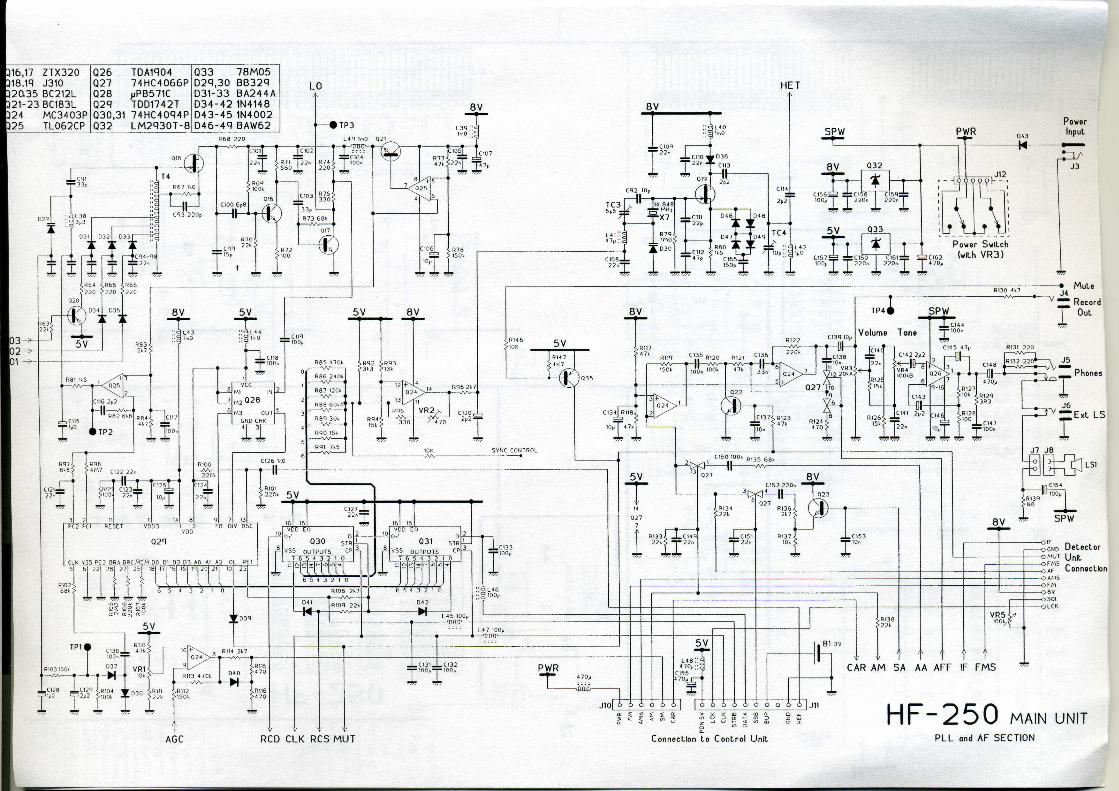
Circuit description. The HF-250 is a dual conversion super heterodyne receiver,
using up-conversion to a high frequency first IF of 45 MHz
and a second IF of 455 kHz for the selective filters. This
design gives good IF image rejection at all tuned frequencies
in the HF band, coupled with good filter shape factors in the
455 kHz IF.
Signals from the aerial pass through one of six band
selecting filters before the first mixer. These filters attenuate
strong signals that are well separated from the frequency
being received, and help to reduce interference from even
order intermodulation distortion. Particular attention has
been paid to separating strong medium wave signals from
the rest of the HF spectrum, and to attenuating signals above 30 MHz which may be received as IF images.
There is no RF stage before the first mixer, and this, coupled with the use of a high performance transistor-tree mixer,
gives the HF-250 a high dynamic range and good resistance
to strong signal overload. A four-pole crystal filter with a 15
kHz bandwidth in the first IF (at 45 MHz) limits the signals
fed to the second mixer and removes image responses from
the second IF.
Most gain in the receiver is in the 455 kHz second IF stage, where amplifiers and filters are interspersed in a chain. The receiver uses ceramic multi-element filters in this IF, and switches in as many as possible for a selected bandwidth :-
2.2 kHz bandwidth :2.2, 4 and 10 kHz filters
4 kHz bandwidth :7 ,4 and 10 kHz filters
7 kHz bandwidth :7 and 10 kHz filters
10 kHz bandwidth :10 kHz filter.
At the end of the second IF, a f ui I-wave envelope detector serves as a low-distortion AM detector and an AGC source. When excessive levels of signal (noise spikes) are detected it fires a noise blanker monostable which in turn mutes the audio output. The IF signal also feeds a product detector which is used for detection in SSB and CW modes, where the IF is mixed with a carrier signal. Audio signal filtering is provided by a high Q peaked response filter centred on 800 Hz which is switched in for the 200 Hz CW filter. The tone control uses an R/C bridge circuit to give either LF or HF cut, with a central flat response position. Receiver tuning is achieved by varying the frequency of both the local oscillator and the IF conversion (heterodyne) oscillator.
The local oscillator covers 45.030 to 74.999 MHz in 1 kHz steps, and fine tuning is provided by the heterodyne oscillator covering 44.544 to 44.545 MHz in 128 steps. The final carrier insertion frequency is determined by the mode selected so that the IF filter passband is in the correct position relative to the carrier for USB or LSB reception.
36 HF-250 User Manual HF250 User Manual 37
Only the local oscillator signal is produced by a phase-locked-loop frequency synthesiser, but all frequencies affecting the receiver are crystal derived to ensure good frequency accuracy and low drift in operation.
All the switching and tuning functions in the receiver are under the control of a dedicated microprocessor system, which receives commands from the front panel controls and sends information to the receiver control register and the PLL system on serial data busses. The single-chip microprocessor is supported by controllers driving the liquid crystal display and a frequency memory chip.
All these components are mounted separately from the main RF and IF circuits on a PCB behind the front panel. The control system is designed to use the "static idle" principle, whereby there are no signals (other than a basic doek oscillator) in the system until the operator requires a change in the receiver condition. The system then reacts to commands from the receiver's controls before retuming to its static condition once again. This method of operation virtually eliminates spurious signals from the control system being picked up by the receiver's input stages.
Receiver specification.
Frequency coverage
30 kHz to 30 MHz continuous coverage.
Reception modes
AM, LSB, USB, CW, (Narrow band FM . Synchronous AMS
DSB,USB,LSB, with the DU250 option).
Receiver system
Microprocessor controlled PLL tuning, dual conversion super
heterodyne receiver.
First intermediate frequency 44.999 MHz to 45.000 MHz. Second intermediate frequency 455 kHz.
R F Input tuning in six bands 1. Below 500 kHz 2. 500 kHz to 1.7 MHz 3. 1.7 MHz to 4.2 MHz 4. 4.2 MHz to 11 MHz 5. 11 MHzto19MHz 6. 19 MHz to 30 MHz
Displays
6-digit backlit LCD showing receiver frequency to the
nearest 100 hertz.
Mode
Indicated by LED mode panel.
Additional indicators show memory mode and AMS detector
lock. Analogue signal strength meter, calibrated S1 to S9,
+10dB,+30dBand +50dB.
Tuning
Spin-wheel, MHz band buttons and Direct keypad frequency
entry. Tuning rates : CW, SSB and AMS AMSL AMSU modes - 8
Hz steps, 1.8 kHz per revolution.
AM mode - 50 Hz steps, 11 kHz per revolution.
FM mode -125 Hz steps, 11 kHz per revolution.
Tuning step size increases with rapid rotation.
Keypad frequency entry is to 1 kHz resolution.
Memories

38 HF-250 User Manual HF250 User Manual 39
255 frequency memories selected with tuning spin-wheel. Data held for 10years. Memories 1 to 255 can be selected from the keypad. Memory functions : Store, Recall, Preview and Channel. Two tuneable frequency stores, A and B. Current tuned frequency and mode is saved when
receiver is switched off.
Operator selectable 2.2, 4, 7 and 10 kHz.
Operator selectable 2.2, 4, 7 and 12 kHz. 2.2
kHz. 12 kHz. (750 us audio de-emphasis).
Audio filters
200 Hz wide audio peak filter centred on 800Hz,
selectable in CW mode.
R F attenuator
Operator selectable 20 dB attenuator.
Controls
Power on/off and Volume control. Tone control (high pass / low pass). Modes - CW, LSB, USB, FM, AMS.AMSL, AMSU, AM.
Memory mode select button. RF attenuator / Memory CHANNEL button.
Filter select / Memory RECALL button.
MHz Down / Memory STORE button.
MHz Up / Memory STORE button.
Fast tune button. Mode button.
the
Tuning / Memory select spin-wheel. Aerial select switch (on rear panel). FM squelch level (on rear panel).
Aerial inputs
50n input via SO-239 socket.
600 Q. Input and Earth connection on spring terminals, also we have a mute contact. Active low.
High-impedance active aerial input for whip antenna via SO-239 socket.
Audio outputs
Record output at approx 350 mV (3.5mm jack socket). External loudspeaker (3.5mm jack socket).
Headphone output (mono or stereo headphones) (6mm
jack).
The intemal loudspeaker is disconnected when headphones
or an external loudspeaker are plugged in.
Power supply
External 12V DC supply (2.1 mm power jack).
230V AC Mains power unit supplied as Standard.
110VAC
Dimensions
Size 280 x 105 x 205 mm (WxHxD, overall).
Weight approx 2.7 kg .
Receiver Performance.
Sensitivity
I F filters
SSB and AM
AMS: CW:
FM:

HF250 User Manual 41
Signal levels are in micro-volts PD across the 50Q aerial input.
AM and SSB sensitivity measured with 10 dB signal/noise ratio at
the receiver output. FM sensitivity measured for 12dB SINAD.
AM signal - modulated to 70% depth at 1 kHz. FM signal -
deviated by 3 kHz at 1 kHz. SSB signal - unmodulated, resolved
at 1 kHz.
Receiver Frequency
60 kHz to 2 MHz AM <1.0 typically 0.7
FM <0.8 typically 0.6
SSB <0.6 typically 0.3
2 MHz to 30 MHz AM <0.7 typically 0.5
FM <0.6 typically 0.4
SSB <0.2 typically 0.15 nV
Bandwidth (kHz) (Shape factor 6:60 dB)
2.3 at -6dB 3.4 at -60dB 5.5 at -80dB SF
1:1.5
9.8at-60dB 10.7at-80dB
12.9at-60dB 14.6at-80dB
21.5at-60dB
FM Adjacent channel selectivity : 12.5 kHz channels 40 dB (1.5 kHz deviation) 25 kHz channels 65 dB (3.0 kHz deviation) FM Signal capture ratio 9 dB
Dynamic range Reciprocal mixing effects : (2.2 kHz filter)
80 dB at 5 kHz from wanted signal. 90 dB at 10 kHz from wanted signal. 105 dB at » 100 kHz from wanted signal.
Intermodulation effects : (2.2 kHz filter)At 10 kHz signal separation, 3rd order intercept point » +4 dBm Intermodulation-free dynamic range » 90 dB At >50 kHz signal separation, 3rd order intercept point » +13 dBm Intermodulation-free dynamic range » 96 dB
Spurious responses
Images :
Fixed responses :
Frequency stability
(Typical performance
only - not guaranteed spec) At a constant 20 Deg C Drift 10~Hz
in one hour, Frequency error < +- 50 Hz.
SSB carrier point attenuation (2.2 kHz filter) 20 dB. CW mode filter position : (ref carrier frequency) -6dB points at -0.8 kHz and +1.35 kHz Resolved audio 800 Hz at carrier frequency. 200 Hz audio filter centered on 800 Hz, Bandwidth 170 Hz at -6dB, 850 Hz at -20dB.
AGC characteristics
Input signal level
(AM mode) -11
dB
Audio output level
(SSB mode) -21 dB (noise only)
Selectivity
I F Filter
2.2 kHz
4 kHz
7 kHz
5.9at-6dB SF
1:1.7
8.8at-6dB SF 1:1.5
10.5at-6dB
SF 1:2
10 kHz
75 dB rejection 90 dB rejection 85 dB rejection 100 dB rejection 75 dB rejection
At +90 MHz At+910 kHz At 45 MHz At 455 kHz At 22.5 MHz
No signal

42 HF-250 User Manual HF250 User Manual 43
0.5V -2 dB -7 dB
5V 0 dB -1dB
50V 0 dB 0dB (ref level)
100mV +0.5 dB +2 dB (AGC limit)
AM mode : Attack time 500 ms for 60 dB level change
Release rate 30 dB per second
SSB mode : Attack time « 10 ms for 60 dB level change
Release rate 40 dB per second
Noise blanker
Audio blanking triggered by IF signal level. Permanently enabled,
operates on all reception modes. Blanking period 500 ms.
Threshold level 12 dB above normal carrier.
Audio output 1.6 W into 8Q at 5% THD (With 12V power supply unit).2.0
W into 4 Q 5% THD (With 12V power supply unit). External loudspeaker output is suitable for loudspeakers with
impedance's of 4Q or greater. Headphone output :up to 4 volts from 220Q
Record output: 350 to 400 mV from 5 KQ
Frequency response
(Tone control in central position)
SSB mode : 2.2 kHz filter 370 Hz to 2.5 kHz (-6dB)
AM mode : 2.2 kHz filter 40 Hz to 1.1 kHz (-6dB)
4 kHz filter 40 Hz to 3.1 kHz (-6dB)
7 kHz filter 40 Hz to 4.3 kHz (-6dB)
10 kHz filter 40 Hz to 5.2 kHz (-6dB)
Tone control action (7 kHz filter, AM mode)
High pass (clockwise) 330 Hz to 4.4 kHz (-6dB)
Flat (central) 40 Hz to 4.3 kHz (-6dB)
Low pass (c/clockwise) 40 Hz to 1.4 kHz (-6dB)
Distortion
AM mode : 1 kHz signal modulated at 70% depth. With Standard AM detector: THD 1 %
With synchronous detector: THD 0.6%
SSB mode : 1 kHz resolved signal THD 0.2%
Two-signal IM products >35 dB below wanted signals, with signal separation > 180 Hz. AMS Detector Lock range : +/- 200 Hz
Audio distortion under carrier-fade conditions : Signal modulated to 70% depth at full carrier level.
6 dB carrier reduction : 2.8% THD (23% with conventional AM
detector).
10 dB carrier reduction : 4.0% THD (39% with conventional AM
detector).
20 dB carrier reduction : 4.1% THD (50% with conventional AM
detector).
Signal to Noise ratio
AM mode : 7 kHz filter, ref 70% modulation. Input signal S/N Weighted S/N
5uV 29 dB 33 dB
>50 uV 47 dB 52 dB
SSB mode : 5 uV 34 dB 37 dB
>50uV 50 dB 54 dB
Weighting to CCITT P.53A telephonic filter. Power supply DC
supply 10 to 15 V (12 V nominal).Quiescent current 250 mA (no
options, no audio output).Typical power consumption 400 to 500
mA.
Specification subject to change without notice.