hermetic protectors for refrigeratio … metals and controls... · hermetic protectors for...
TRANSCRIPT
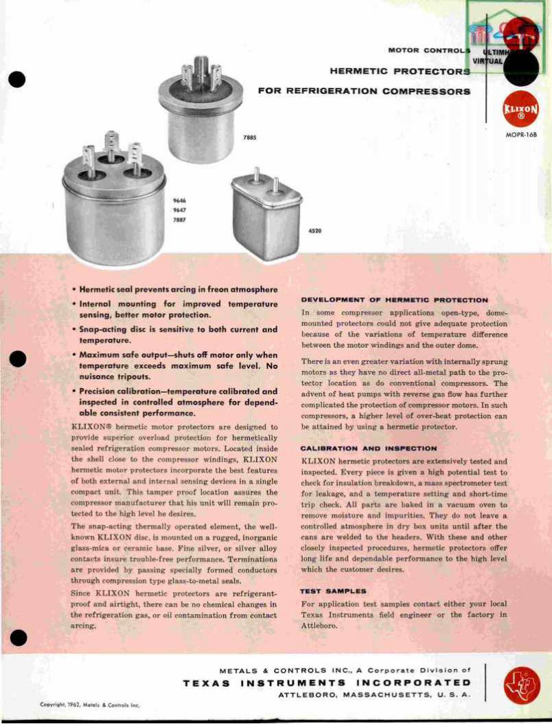
M O T O R C O N T R O L S
H E R M E T I C P R O T E C T O R S
F O R R E F R I G E R A T I O N C O M P R E S S O R S
• Hermetic seal prevents arcing in freon atmosphere
• Internal mounting for improved temperature sensing, better motor protection.
• Snap-acting disc is sensitive to both current and temperature.
• Maximum safe output—shuts off motor only when temperature exceeds maximum safe level. No nuisance tripouts.
• Precision calibration—temperature calibrated and inspected in controlled atmosphere for depend-able consistent performance.
KLIXON® hermetic motor protectors are designed to provide superior overload protection for hermetically sealed refrigeration compressor motors. Located inside the shell close to the compressor windings, KLIXON hermetic motor protectors incorporate the best features of both external and internal sensing devices in a single compact unit. This tamper proof location assures the compressor manufacturer that his unit will remain pro-tected to the high level he desires.
The snap-acting thermally operated element, the well-known KLIXON disc, is mounted on a rugged, inorganic glass-mica or ceramic base. Pine silver, or silver alloy contacts insure trouble-free performance. Terminations are provided by passing specially formed conductors through compression type glass-to-metal seals. Since KLIXON hermetic protectors are refrigerant-proof and airtight, there can be no chemical changes in the refrigeration gas, or oil contamination from contact arcing. % r-
D E V E L O P M E N T O F H E R M E T I C P R O T E C T I O N
In some compressor applications open-type, dome-mounted protectors could not give adequate protection because of the variations of temperature difference between the motor windings and the outer dome.
There is an even greater variation with internally sprung motors as they have no direct all-metal path to the pro-tector location as do conventional compressors. The advent of heat pumps with reverse gas flow has further complicated the protection of compressor motors. In such compressors, a higher level of over-heat protection can be attained by using a hermetic protector.
C A L I B R A T I O N A N D I N S P E C T I O N
KLIXON hermetic protectors are extensively tested and inspected. Every piece is given a high potential test to check for insulation breakdown, a mass spectrometer test for leakage, and a temperature setting and short-time trip check. All parts are baked in a vacuum oven to remove moisture and impurities. They do not leave a controlled atmosphere in dry box units until after the cans are welded to the headers. With these and other closely inspected procedures, hermetic protectors offer long life and dependable performance to the high level which the customer desires.
T E S T S A M P L E S
For application test samples contact either your local Texas Instruments field engineer or the factory in Attleboro.
M E T A L S & C O N T R O L S INC., A Corporate Div is ion of
T E X A S I N S T R U M E N T S I N C O R P O R A T E D ATTLEBORO, M A S S A C H U S E T T S , U. S . A.
Copyright, 1962, Metals & Controls Inc.
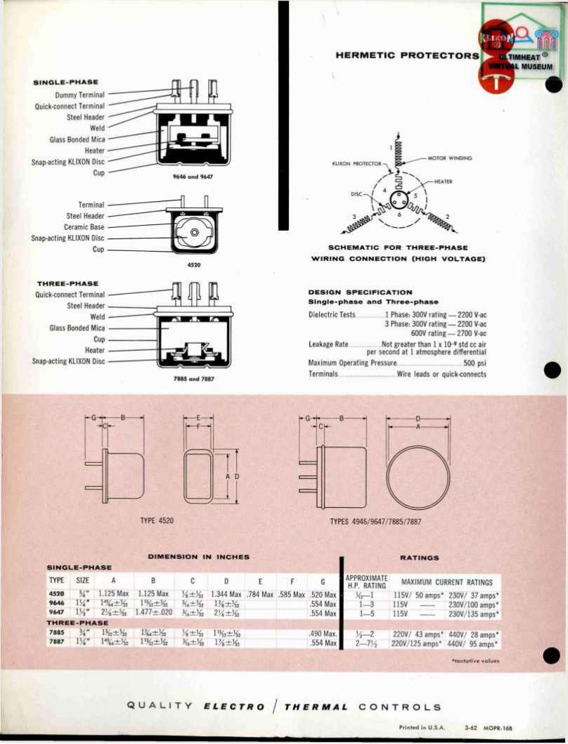
S I N G L E - P H A S E
Dummy Terminal
Quick-connect Terminal
Steel Header
Weld
Glass Bonded Mica
Heater
Snap-acting KLIXON Disc
Cup
Terminal
Steel Header
Ceramic Base
Snap-acting KLIXON Disc
Cup
9646 and 9647
H E R M E T I C P R O T E C T O R S
MOTOR WINDING KLIXON PROTECTOR
4520
S C H E M A T I C F O R T H R E E - P H A S E
W I R I N G C O N N E C T I O N ( H I G H V O L T A G E )
T H R E E - P H A S E
Quick-connect Terminal
Steel Header
Weld
Glass Bonded Mica
Cup
Heater
Snap-acting KLIXON Disc
7885 and 7887
D E S I G N S P E C I F I C A T I O N
S i n g l e - p h a s e a n d T h r e e - p h a s e
Dielectric Tests 1 Phase: 300V rating — 2200 V-ac 3 Phase: 300V rating — 2200 V-ac
600V rating — 2 7 0 0 V-ac
Leakage Rate Not greater than 1 x 10-' std cc air per second at 1 atmosphere differential
Maximum Operating Pressure 500 psi
Terminals Wire leads or quick-connects
A D
TYPE 4520 TYPES 4946/9647/7885/7887
D I M E N S I O N IN I N C H E S
TYPE SIZE A B C D E F G APPROXIMATE H.P. RATING MAXIMUM CURRENT RATINGS
4520 3A" 1.125 Max 1.125 Max 1.344 Max .784 Max .585 Max .520 Max J f r - l 115V/ 50 amps* 230V/ 37 amps* 9646 W i k ± J 6 .554 Max 1—3 115V 230V/100 amps* 9647 V/2" 1.477±.020 2A±V32 .554 Max 1—5 115V 230V/135 amps*
T H R E E - P H A S E
7885 y* 1 %±Vl2 .490 Max. > 4 - 2 220V/ 43 amps* 440V/ 28 amps* 7887 VA" 1 V/s±V32 .554 Max 2-7% 220V/125 amps* 440V/ 95 amps*
R A T I N G S
•tentative values
Q U A L I T Y ELECTRO / THERMAL C O N T R O L S
Printed in U.S.A. 3-62 MOPR-16B

Q
n PRET-9B
Actual Size
Narrow differential • control High reliability
- provides close temperature
• We lded seams assure better hermetic seal — eliminate corrosive solder fluxes
• Designed to easily fit small, narrow spaces
• Can be supplied to open or close on temperature rise
• Pre-set temperature settings — tamperproof
The K L I X O N ® M2 thermostat is a simple, snap-acting mechanism designed to provide precise temperature control within exceptionally narrow limits. The thermal control ele-ment consists of a basic snap-acting, KLIXON disc and fine silver contacts — mounted in a silicone-ceramic base. This assembly is hermetically welded in a flat, nickel plated steel shell. The terminals pass through glass-to-metal seals.
The exclusive all-welded construction — a process perfected through years of K L I X O N thermostat production-elimi-nates the use of organic substances commonly found in units having a soldered seal (solder fluxes often leave deposits of
.063 DIA. HOLE
contaminants inside the device which tend to corrode and shorten the expected service life of the thermostat).
M2 thermostats are recommended for use as controls and warning devices in guided missiles, aircraft controls, heat-ing blankets, electronic circuit components, servo mechan-isms, gyroscopes, aerial cameras, crystal ovens, surface heaters, computers, and similar electronic devices where reliable performance is vital.
L . i .300°°
* .660°DIA. — » ' ' " L
.015
L o o s e M o u n t i n g B r a c k e t
4 5 ° A n g l e T e r m i n a l s S t r a i g h t T e r m i n a l s R i g h t A n g l e T e r m i n a l s
Tolerances ±.010 unless otherwise specified. Dimensions shown in inches and are subject to change without notice. Send for up-to-date drawings.
Copyright, 1964 Metals & Controls Inc.
M E T A L S S ATTLEBORO
C O N T R O L S I I M C . MASSACHUSETTS. U S A.
C O R P O R A T E D 1 V I
T E X A S I N S T R U M E N T S I N C O R P O R A T E D
P R E C I S I O N C O N T R O L S
P R E C I S I O N T H E R M O S
N A R R O W D I F F E R E N T I A L
W E L D E D S E A M S
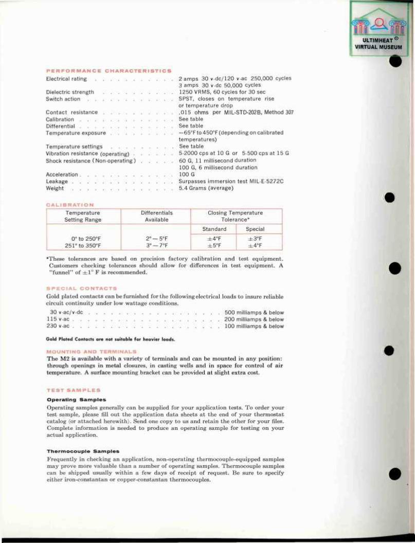
P E R F O R M A N C E C H A R A C T E R I S T I C S
Electrical rating 2 amps 30 v-dc/120 v-ac 250,000 cycles 3 amps 30 v-dc 50,000 cycles
Dielectric strength 1250 VRMS, 60 cycles for 30 sec Switch action SPST, closes on temperature rise
or temperature drop Contact resistance 015 ohms per MIL-STD-202B, Method 307 Calibration See table Differential See table Temperature exposure —65°Fto 450°F(depending on calibrated
temperatures) Temperature settings See table Vibration resistance (operating) 5-2000 cps at 10 G or 5-500 cps at 15 G Shock resistance ( Non-operating ) 60 G, 11 millisecond duration
100 G, 6 millisecond duration Acceleration 100 G Leakage Surpasses immersion test MIL-E-5272C Weight 5.4 Grams (average)
C A L I B R A T I O N
Temperature Differentials Closing Temperature Setting Range Available Tolerance*
Standard Special
0° to 250°F 2° — 5°F ± 4 ° F ± 3 ° F 251° to 350°F 3° — 7°F ± 5 ° F ± 4 ° F
*These tolerances are based on precision factory calibration and test equipment. Customers checking tolerances should allow for differences in test equipment. A "funnel" of ±1 ° F is recommended.
S P E C I A L C O N T A C T S
Gold plated contacts can be furnished for the following electrical loads to insure reliable circuit continuity under low wattage conditions.
30 v-ac/v-dc 500 milliamps & below 115 v-ac 200 milliamps & below 230 v-ac 100 milliamps & below
Gold Plated Contacts are not suitable for heavier loads.
M O U N T I N G A N D T E R M I N A L S
The M2 is available with a variety of terminals and can be mounted in any position: through openings in metal closures, in casting wells and in space for control of air temperature. A surface mounting bracket can be provided at slight extra cost.
T E S T S A M P L E S
O p e r a t i n g S a m p l e s
Operating samples generally can be supplied for your application tests. To order your test sample, please fill out the application data sheets at the end of your thermostat catalog (or attached herewith). Send one copy to us and retain the other for your files. Complete information is needed to produce an operating sample for testing on your actual application.
T h e r m o c o u p l e S a m p l e s
Frequently in checking an application, non-operating thermocouple-equipped samples may prove more valuable than a number of operating samples. Thermocouple samples can be shipped usually within a few days of receipt of request. Be sure to specify either iron-constantan or copper-constantan thermocouples.
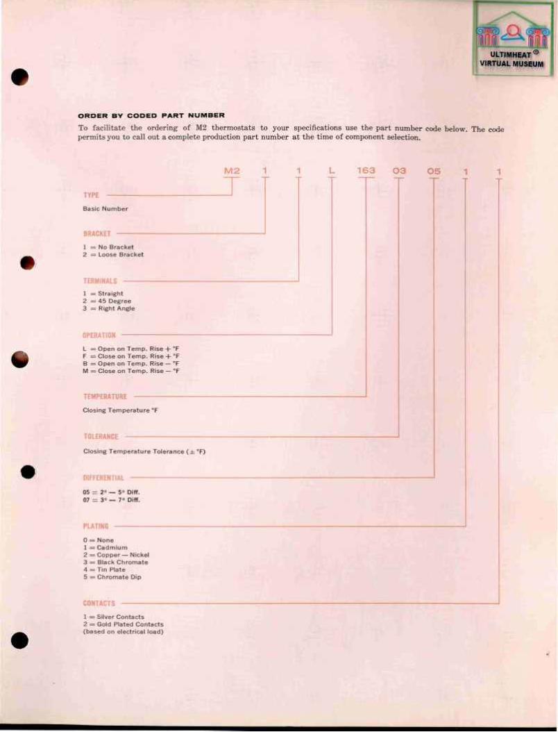
O R D E R BY C O D E D F A R T N U M B E R
To facilitate the ordering of M2 thermostats to your specifications use the part number code below. The code permits you to call out a complete production part number at the time of component selection.
M 2 1 1 L 163 0 3 0 5 1 1
TYPE
Basic Number
BRACKET
1 = No Bracket 2 = Loose Bracket
TERMINALS
1 = Straight 2 = 45 Degree 3 = Right Angle
OPERATION
L — Open on Temp. Rise -F °F F = Close on Temp. Rise 4- ° F B = Open on Temp. Rise — °F M = Close on Temp. Rise — °F
TEMPERATURE
Closing Temperature ° F
TOLERANCE
Closing Temperature Tolerance (=t°F)
DIFFERENTIAL —
05 = 2° — 5° Diff. 07 = 3° — 7° Diff.
PLATING
0 = None 1 = Cadmium 2 = Copper— Nickel 3 — Black Chromate 4 = Tin Plate 5 = Chromate Dip
CONTACTS
1 = Silver Contacts 2 = Gold Plated Contacts (based on electrical load)
ULTIMHEAT ® VIRTUAL MUSEUM
m au
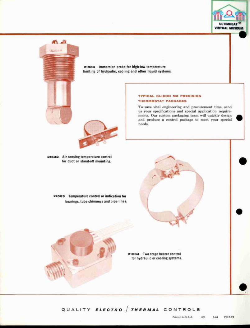
21504 Immersion probe for high-low temperature limiting of hydraulic, cooling and other liquid systems.
T Y P I C A L K L I X O N M 2 P R E C I S I O N
T H E R M O S T A T P A C K A G E S
To save vital engineering and procurement time, send us your specifications and special application require-ments. Our custom packaging team will quickly design and produce a control package to meet your special needs.
21532 Air sensing temperature control for duct or stand-off mounting.
21563 Temperature control or indication for bearings, tube chimneys and pipe lines.
o I x I « »
J S > .
4 M 21564 Two stage heater control for hydraulic or cooling systems.
Q U A L I T Y ELECTRO / THERMAL C O N T R O L S
Printed in U.S.A. 5M 3-64 PRET-9B

FOR
T H P R - 1 1
M J E open t y p e 9644 h e r m e t i c a l l y s e a l e d
FEATURES
• Max imum Motor Output Consistent wi th System Requirements — motor shuts down only when maxi -mum allowable temperature is reached.
• Complete Overtemperature Protection — against such causes as:
• P ro l onged o v e r l o a d s • S ta l l ing • Lack of ven t i l a t i on
• Fa i lure to start • Excess ive amb i en t t empe ra tu re • U n b a l a n c e d v o l t a g e
• Shock and Vibrat ion Resistant — high contact pres-sure continuously maintained by Spencer snap-acting disc.
• Long Contact Life — fine silver-clad contacts, termi-nals, and special components assure long life.
• Fungus Resistant — mycalex, silicone or phenolic housings, depending upon temperature requirements.
• Dependable Operat ion — single construction — only one moving part — insures reliability.
G E N E R A L
High performance electric motors require overtempera-ture protection designed to match their special operating requirements. KLIXON Precision Inherent Overtempera-ture Protectors are designed to meet these requirements without limiting useful motor output. Motors equipped with KLIXON inherent protection develop maximum operating capacity under a l l overload conditions while eliminating danger of motor burnout. Present usage ranges from miniature camera motors to fuel pump motors and large actuator and blower motors.
DESCR I PT ION The KLIXON Inherent Overheat Protector is a small, light weight, temperature and current'sensitive device that is built into an electtic motor to turn off the power when the windings get too hot. Mounted inside the motor, the protector is aware of motor temperature at all times. The single operating element of the KLIXON Protector is the famous Spencer snap-acting disc. Fine silver clad contacts are mounted directly on the disc. Terminals are also silver clad. Solder connections are standard, but screw-type connections are available. Fungus resistant mycalex, silicone or phenolic housings are supplied, de-pending on temperature requirements.
To meet the requirements of a three-phase motor operat-ing on one, two or three phases, KLIXON Three-Phase Protectors have a heater connected in each motor phase. The disc serves to close the neutral point of the motor and also carries phase current. Thus, the one protector performs the function of three separate devices but with the advantage of less weight, smaller size and greater reliability.
Copyright, 1963, Metals & Controls Inc.
M E T A L S Sl C O N T R O L S I N C . ATTLEBORO • M AS S AC H U S ET TS. U. S. A. A C O R P O R A T E D I V I S I O N O F
T E X A S I N S T R U M E N T S I N C O R P O R A T E D
PRECISION
PRECISION THERMAL PROTECTORS THREE-PHASE ELECTRIC MOTORS
OPEN TYPES
ESTIMATED CAPACITY PROTECTOR APPROXIMATE
HORSEPOWER Continuous Duty
MAXIMUM RUPTURE CAPACITY
(200 V., 400 cycl«<) TYPE SIZE
APPROXIMATE HORSEPOWER
Continuous Duty
MAXIMUM RUPTURE CAPACITY
(200 V., 400 cycl«<)
S J V»" to VA 30 amperes MJ V* to 3 60 amperes BJ VA" 2 to 10 120 amperes
HERMETICALLY SEALED TYPE Originally designed for overtemperature protection of three-phase, four-wire aircraft fuel pump motors, the 9644 type is equally suitable for use in other explosive atmospheres. The basic protector is the well-proven KLIXON S JE Type, operating either as an automatic or non-reset device. Special mounting flanges can be made to meet customer requirements.
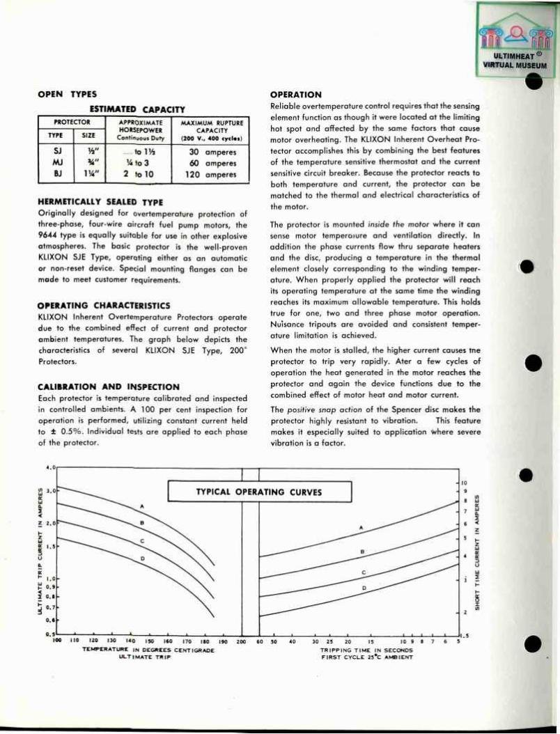
OPERATING CHARACTERISTICS KLIXON Inherent Overtemperature Protectors operate due to the combined effect of current and protector ambient temperatures. The graph below depicts the characteristics of several KLIXON SJE Type, 200° Protectors.
CALIBRATION AND INSPECTION Each protector is temperature calibrated and inspected in controlled ambients. A 100 per cent inspection for operation is performed, utilizing constant current held to ± 0 .5%. Individual tests are applied to each phase of the protector.
OPERATION Reliable overtemperature control requires that the sensing element function as though it were located at the limiting hot spot and affected by the same factors that cause motor overheating. The KLIXON Inherent Overheat Pro-tector accomplishes this by combining the best features of the temperature sensitive thermostat and the current sensitive circuit breaker. Because the protector reacts to both temperature and current, the protector can be matched to the thermal and electrical characteristics of the motor.
The protec tor is m o u n t e d inside the motor w h e r e it c a n sense motor temperorure and ventilation directly. In addition the phase currents flow thru separate heaters and the disc, producing a temperature in the thermal element closely corresponding to the winding temper-ature. When properly applied the protector will reach its operating temperature at the same time the winding reaches its maximum allowable temperature. This holds true for one, two and three phase motor operation. Nuisance tripouts are avoided and consistent temper-ature limitation is achieved.
When the motor is stalled, the higher current causes tne protector to trip very rapidly. Ater a few cycles of operation the heat generated in the motor reaches the protector and again the device functions due to the combined effect of motor heat and motor current.
The positive snap action of the S p e n c e r disc m a k e s the protector highly resistant to vibration. This feature makes it especially suited to application V/here severe vibration is a factor.
110 120 130 u o 150 l«0 170 110 190 TEMPERATURE IN DEGREES CENTIGRADE
ULTIMATE TRIP
30 25 20 15 10 9 TRIPP ING TIME IN SECONDS F IRST CYCLE 25*C AMBIENT

ULTIMHEAT ® VIRTUAL MUSEUM
RATINGS
Standard ratings are avai lable in approximately 5 % current steps at ultimate trip for motors with maximum allowable temperatures of 150°, 175° and 200°C. Special operating temperatures or ratings can be produced as required. The stalled rotor first cycle trip time can be varied at each ultimate trip point to match this motor characteristic.
Physical size of the protector is determined by the stalled rotor current that must be ruptured. For capacity of each size, see the table o f estimated capacity on the
opposite page. Maximum current based on 200 volts, 400 cycles is 400 amperes.
MOUNTING The protector should be located in the motor so that it will receive the maximum amount of heating from the windings, not only for running but also for stalled rotor conditions. The degree of protection obtained depends to a large extent upon the protector location and its manner of mounting. The best location depends upon the construction of the motor; but, in general, may be the air-shield, end-bell or possibly the stator iron and preferably in the discharge air.
TYPE SJE
OPEN TYPES
DIMENSIONS IN INCHES
TYPES BJE AND MJE
P R O T E C T O R D I M E N S I O N S ( i n i n c h » , )
T y p e
A p p r o x . W e i g h t
( O u n c e » )
A M A X . B C D E F
G
D i a m e t e r H
S J E \ 1 . 0 7 2 . 7 1 8 + . 0 0 5 . 298 ±.015 . 630 ±.010 . 1 5 6 M A X . . 8 1 2 ± . 0 0 2 . 090 ±.003
M J E 1 .635 .970±.OO5 . 390 ±.010 . 8 6 3 ± . 0 1 0 . 1 8 8 M A X . 1 .312±.006 . 152±.005 . 250 ±.010
B J E 2 yt 2 . 4 5 7 +.000
1 .562 . 0 1 5 . 609 ±.005 1.344 ±.010 . 3 1 2 M A X . 1 .937±.010 +.005
. 2 1 8 - . 0 0 0 .250 ±.010
APPLICATION DETAILS For specific information concerning the selection of pro-tector ratings, contact Spencer products group,Attleboro, Mass. or our local field engineer.
Suggested motor test procedure and forms for recording
data are available upon request. These forms are identi-fied as follows:
Suggested Test Procedure IN-MOPR-11 Application Data Form AD-MOPR-11 Verification Test Data V-MOPR-11

ULTIMHEAT ® VIRTUAL MUSEUM
HERMETICALLY SEALED TYPE
Approximate weight - V/l ozs.
N • DESIGNATES NEUTRAL TERMINAL
(2 PLACES)
.0002 .0003 CADMIUM PLATE EXCEPT TERMINALS WHICH ARE .0001-.0002 SILVER
9644
K u x o N Q U A L I T Y ELECTRO / THERMAL C O N T R O L S
P R I N T E D I N U . S . A . 7 - 6 3 T H P R - 1 1
TYPICAL C4344 APPLICATIONS
• G R O U N D S U P P O R T E Q U I P M E N T • E L E C T R O N I C A N D R A D A R E Q U I P M E N T
• FUEL P U M P M O T O R S • G Y R O S
• C A B I N A I R C O N D I T I O N I N G SYSTEMS • A C C E L E R O M E T E R S
• A E R I A L C A M E R A S • M I SS I L E H E A T I N G B L A N K E T S
• P O W E R TUBES
• B E A R I N G S S U B J E C T TO O V E R H E A T C O N D I T I O N S
PRET-2A
P R E C I S I O N C O N T R O L S
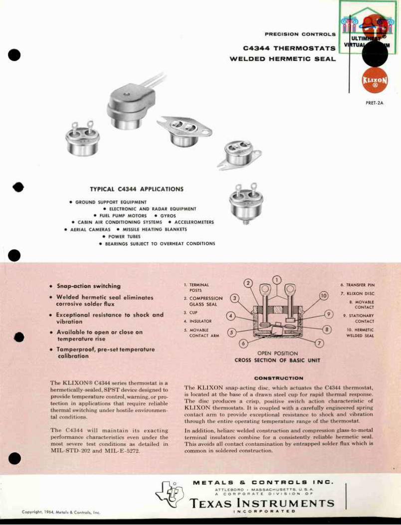
C 4 3 4 4 T H E R M O S T A T S
W E L D E D H E R M E T I C S E A L
• Snap-action switching
• We lded hermetic seal eliminates corrosive solder flux
• Exceptional resistance to shock and vibration
• Ava i lab le to open or close on temperature rise
• Tamperproof, pre-set temperature calibration
1. TERMINAL POSTS
2. C O M P R E S S I O N G L A S S S E A L
3. CUP
4. INSULATOR
5. MOVABLE CONTACT ARM
6. TRANSFER P IN
7. K L I X O N DISC
8. MOVABLE CONTACT
9. STATIONARY CONTACT
10. HERMETIC WELDED SEAL
OPEN POSITION CROSS SECTION OF BASIC UNIT
The KLIXON® C4344 series thermostat is a hermetically-sealed, SPST device designed to provide temperature control, warning, or pro-tection in applications that require reliable thermal switching under hostile environmen-tal conditions.
The C4344 will maintain its exacting performance characteristics even under the most severe test conditions as detailed in MIL-STD-202 and MIL-E-5272.
C O N S T R U C T I O N
The K L I X O N snap-acting disc, which actuates the C4344 thermostat, is located at the base of a drawn steel cup for rapid thermal response. The disc produces a crisp, positive switch action characteristic of K L I X O N thermostats. It is coupled with a carefully engineered spring contact arm to provide exceptional resistance to shock and vibration through the entire operating temperature range of the thermostat. In addition, heliarc welded construction and compression glass-t.o-metal terminal insulators combine for a consistently reliable hermetic seal. This avoids all contact contamination by entrapped solder flux which is common in soldered construction.
M E T A L S fi. ATTLEBO RO
C O N T R O L S I N C . M A S S A C H U S E T T S . U .S .A .
C O R P O R A ~ V I S I O N O F
T E X A S I N S T R U M E N T S Copyright, 1964, Metals & Controls, Inc. I N C O R P O R A T E D

NO BRACKET FLATTENED & PIERCED
TERMINALS
ULTIMHEAT ® VIRTUAL MUSEUM
H h
P E R F O R M A N C E C H A R A C T E R I S T I C S
Dielectric strength (without breakdown or
current leakage in excess of one mil l iampere)
Calibration
Differential
Swi tch action
Ambient temperature range
Life cycle
Contact resistance
Accelerat ion
Shock resistance
Vibration resistance*
Sand and dust
Humidity
Sa l t spray
Leakage
Weight (avg)
1250 v-ac, rms, 60 cycles for 1 min, terminal to case; 1000 V-ac, rms, 60 cycles for 1 min, terminal to terminal with contacts open; Per MIL-STD-202B, Method 301
See temperature settings table
See temperature settings table
S P S T , (snap-action)
— 8 0 ° F to +500°F continuous (non-overmolded units available for exposure to —320 °F when required)
See contact ratings table
0.015 ohms per MIL-STD-202B, Method 307
60 G
60 G, 11 mil l iseconds
5-2000 cps, 20 G per MIL-STD-202B, Method 204A, Condition D
MIL-STD-202B, Method 110, Test Condition A
MIL-STD-202B, Method 103A, Test Condition A
MIL-STD-202B, Method 101A, 168 hrs
Immersion test per MIL-E-5272C or MIL-STD-202B, Method 104A, Condition A
k ™ H
. 1 .292
L - J P MAX "]
NO BRACKET RIGHT ANGLE
TERMINALS
.049 i n
* -.,01 s
.269
t ' .315 J
t .029
L .572 » P MAX
NO BRACKET PIN TERMINALS
Bas ic unit 4.8 gr Bas ic unit with bracket . . . . 5.9 gr Basic unit with overmold,
12" leads 23 gr
C O N T A C T R A T I N G S ( R e s i s t i v e )
* Devices with Group B or C differentials wil l withstand these vibration levels without contact bounce or chatter while thermally operated through their switching cycles, (see temperature settings table — next page)
30 v-ac/dc 125 v-ac 250 V-ac Life
Amperes Cycles
5.0 2.0 1.0 100,000
5.5 3.0 1.5 50,000
6.0 4.0 2.0 25,000
6.5 5.0 2.5 10,000
7.0 6.0 3.0 5,000 ^
Electr ical loads above 5 amps produce some internal heating. The effect on temperature settings varies with the usage should be checked on crit ical applications.
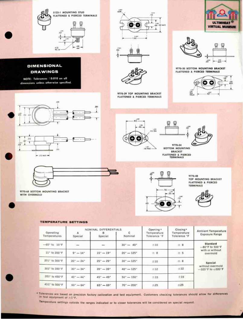
5123-1 MOUNTING STUD FLATTENED & PIERCED TERMINALS
11
D I M E N S I O N A L
D R A W I N G S
NOTE: Tolerances ±0.010 on all dimensions unless otherwise specified.
S r
i . T o
9770-39 TOP MOUNTING BRACKET FLATTENED & PIERCED TERMINALS
U L T I M H E A T
V I R T U A L M U S E U M
J O .
i t Î.005 .021 „ .572 .
MAX
9770-30 BOTTOM MOUNTING BRACKET FLATTENED & PIERCED TERMINALS
3 — E Z Z ^
J L
î t - M 1 -387 —w X 1 - i
625 1 T 1 ^
I
I
Î .305
.572 MAX-»
Î .305
3 - E 1 3 — 9770-54
BOTTOM MOUNTING BRACKET
FLATTENED & PIERCED TERMINALS
9770-68 BOTTOM MOUNTING BRACKET WITH OVERMOLD
T E M P E R A T U R E S E T T I N G S
Operating Temperatures
NOf> A
Specia l
1NAL D I F F E R E N T B
Spec ia l
ALS C
Nominal
Opening * Temperature Tolerance ° F
Closing* Temperature Tolerance ° F
Ambient Temperature Exposure Range
—65° to 10 °F - - 30° — 40 ° ±10 ± 8 Standard — 8 0 ° F to 500 °F with or without
overmold
Specia l without overmold
—320 °F to + 2 2 0 ° F
11° to 200° F 9 ° — 14° 15° — 19° 20° — 125° ± 8 ± 5
Standard — 8 0 ° F to 500 °F with or without
overmold
Specia l without overmold
—320 °F to + 2 2 0 ° F
201° to 300° F 20 ° — 24° 25° — 29° 30 ° — 125° ±10 ± 8
Standard — 8 0 ° F to 500 °F with or without
overmold
Specia l without overmold
—320 °F to + 2 2 0 ° F 301° to 350° F 30 ° — 34° 35 ° — 39° 40 ° — 125° ±12 ±12
Standard — 8 0 ° F to 500 °F with or without
overmold
Specia l without overmold
—320 °F to + 2 2 0 ° F
351° to 450° F 40 ° — 44° 4 5 ° — 4 9 ° 50 ° — 150° ± 1 5 ±15
Standard — 8 0 ° F to 500 °F with or without
overmold
Specia l without overmold
—320 °F to + 2 2 0 ° F
451° to 500° F 60° — 64° 65 ° — 69° 70° — 200° ± 2 5 ±25
Standard — 8 0 ° F to 500 °F with or without
overmold
Specia l without overmold
—320 °F to + 2 2 0 ° F
* Tolerances are based on precision factory calibration and test equipment. Customers checking tolerances should allow for differences in test equipment of ± 1 ° F .
Temperature settings outside the ranges indicated or to closer tolerances wil l be considered on special request.
i

S P E C I A L C O N T A C T S
Gold plated contacts can be furnished for the electrical loads listed in the following table to assure reliable cir-cuit making under low wattage conditions. Gold plated contacts are not suitable for heavier loads.
30 v -ac /dc 115 v-ac 230 v-ac
500 ma and below 200 ma and below 100 ma and below
T E R M I N A L S
Terminal options include right angle, flattened and pierced or straight pin type. In addition, the C4344 thermostat can be supplied with integral leads and sili-cone rubber overmolding for use under extreme condi-tions of humidity, moisture and corrosion.
L E A D S
W i t h o u t O v e r m o l d
The C4344 thermostat can be supplied with wire leads welded to straight pin type or right angle terminals. Leads are #18 AWG with insulation and lead length as specified.
ULTIMHEAT ® VIRTUAL MUSEUM
W i t h S i l i c o n e R u b b e r O v e r m o l d ( D o w C o r n i n g 1 5 2 o r e q u i v a l e n t )
Leads are #18 AWG wire insulated with silicone rubber and are cut to customers' specified length. Lead length is measured from the center of the thermostat to the end of the wire.
T E S T S A M P L E S
O p e r a t i n g S a m p l e s
Operating samples generally can be supplied for your application tests. Please fill in the data sheets at the end of your precision thermostat catalog (or attached) for your test sample. Send one copy to us and retain the other for your files. Complete circuit and environ-mental information is needed to produce an operating sample for testing on your actual application.
T h e r m o c o u p l e S a m p l e s
Frequently, in making an application, non-operating thermocouple-equipped samples may prove more help-ful than a number of operating samples. Thermocouple samples can be shipped usually within a few days of receipt of request. Be sure to specify either iron-constantan or copper-constantan thermocouples.
NO. 2 1 4 4 7
I m m e r s i o n T h e r m o s t a t s
Fast response sensing of coolant and other fluid temperatures
N o . 2 1 4 0 0
F l a n g e - M o u n t e d T h e r m o s t a t s
Temperature protection or warning for critical equipment enclosures
T Y P I C A L K L I X O N C 4 3 4 4 P R E C I S I O N T H E R M O S T A T P A C K A G E S
To save vital engineering and procurement time, send us your specifications and special application require-ments. Our custom packaging team will quickly design and produce a control package to meet your special needs.
H i g h P r e s s u r e T h e r m o s t a t s
Temperature protection or indication for hydraulic systems
N o . 2 1 5 5 6
Q U A L I T Y ELECTRO / THERMAL C O N T R O L S
Printed in U.S.A. 5M 3-64 PRET-2A
N o . 2 1 5 4 0
S t r a p M o u n t e d T h e r m o s t a t s
Over temperature protection for bearings and power tube chimneys.