manual motor protectors, motor protectors with contactor ... · manual motor protectors, motor...
TRANSCRIPT

7
Man
ual M
otor
Pro
tect
ors,
Mot
or P
rote
ctor
s w
ith C
onta
ctor
Mot
or S
tart
er C
ombi
natio
ns
7/2
7/6
7/8
7/107/117/12
7/147/157/167/177/18
7/20
7/24
7/257/26
7/287/297/307/32
7/367/377/377/38
7/397/40
7/427/437/447/47
7/487/497/507/54
7/55
Overview
Manual Motor ProtectorMotor Protector for high inrush loadsMotor Protector Combinations with ContactorNEC Group Motor Application Ratings
Auxiliary ContactsVoltage Trips(High Capacity) Magnetic Contactors + Accessories
Enclosures, HousingsHandles, AccessoriesWiring accessories: Feeder ConnectorsBus Bar AdaptersMounting & Wiring System MVS
Overview
Manual Motor ProtectorMotor Protector Combinations with ContactorNEC Group Motor Application RatingsMotor Protector without Protective Trip ModuleProtective Trip Module
Auxiliary ContactsVoltage TripsRemote Control DrivesHigh Capacity Magnetic Contactors + Accessories
Enclosures, HousingsHandles, AccessoriesWiring accessories: Feeder ConnectorsBus Bar Adapters
System PKZ 0- Motor Protector Coil Voltage RatingsSystem PKZ 2- Motor Protector Coil Voltage Ratings
Technical Data- System PKZ 0 - Motor Protector- Electrical Life Curves- Let-through Current and Energy Curves- General Technical Information- Short Circuit Ratings IEC/EN 60 947
Technical Data- System PKZ 2 - Motor Protector- Electrical Life Curves- Let-through Current and Energy Curves- General Technical Information- Short Circuit Ratings IEC/EN 60 947
Dimensions
Manual Motor Protectors, Motor Protectors with ContactorMotor Starter Combinations
System PKZ 0- Motor Protector
System PKZ 2- Motor Protector
7/1
1
Return To MAIN INDEX
For Immediate Delivery call KMParts.com at (866) 595-9616

7
Manual M
otor Protectors, M
otor Protectors w
ith Contactor
Motor S
tarter Com
binations
7/2
Overview - System PKZ 0 UL/CSA; IEC/EN 60 947; CEManual Motor Protector and Magnetic Motor Protector Combinations
System PKZ 0 refers to all of thecomponents and accessories whichmake up the line of PKZM 0 Motor Protectors.It is a modular system, with ample flexibilityand comprehensive ratings to accommodate a broadrange of industrial control motor switching and protectionrequirements.System PKZ 0 components are in compliance with all pertinentinternational and domestic standards and can be installedworld-wide.Maximum ratings: 25 Amps, 600 V AC
For Immediate Delivery call KMParts.com at (866) 595-9616

7
Man
ual M
otor
Pro
tect
ors,
Mot
or P
rote
ctor
s w
ith C
onta
ctor
Mot
or S
tart
er C
ombi
natio
ns
UL/CSA; IEC/EN 60 947; CE Overview - System PKZ 0Manual Motor Protector and Magnetic Motor Protector Combinations
7/3
Manual Motor ProtectorThermal-Magnetic Motor Protector
Rated up to 25 Amps
Maximum 3 Phase HP rating: 15/ 20 @ 460/ 575 V AC
UL Listed for Group installations per NEC 430-53
CSA Certified for Group installations per CEC Part 1, 28-206
High Short Circuit Rating: Up to 50 kA @ 600 V AC
UL Listed, CSA Certified, in Conformity with IEC/EN 60 947
CE Marked
Type: PKZM 0-...
1
Current Limiter Module
Increases short circuit current rating of the PKZM 0.
Fuseless, current limiting set of contacts housed in a
module.
Mounts directly beneath or ahead of the PKZM 0.Type: CL-PKZ 0
2
Auxiliary Contact Modules
Signals ON/OFF status of PKZM 0 Motor Protector and
Motor Protector + Contactor combination.
Trip indicating contacts which differentiate between overload
and short circuit tripping.
Early-Make contacts for use with undervoltage trips.
Type: NHI-..., AGM-..., VHI-...
3
Door Mounted Handle Rated IP 65/ NEMA/UL 12, 3R.
3 Positions- ON, OFF, Tripped.
Door interlocking feature and padlockable with up to
3 padlocks. (Also available without door interlocking or
padlockable feature.)
Plug-in extension shaft to accommodate various
mounting depths.
Black, or Red/Yellow for E-Stop function
Type: (R)H-PKZ 0, HSOV-PKZ 0
6
Magnetic Contactor ModuleAC or DC operated versions.
Supplied with 1 N.O./1N.C. or 2 N.O. contacts.
Plugs into the load side of the PKZM 0 protector
or can be separately mounted.
Rated 7 1/2 HP @ 460 V AC/ 10 HP @ 575 V AC
UL Listed with PKZM 0 Motor Protector for Group
installations per NEC 430-53.
CSA Certified with PKZM 0 Motor Protector for Group
installations per CEC 28-206.
IEC 60 947-4-1 rated for Type 1 co-ordination.
Type: SE 00-...
4
High Capacity Magnetic Contactor ModuleSame approvals & features as Type SE00 above except:
Internal current limitation feature to increase short circuit
current rating and self-protection characteristics per
IEC/EN 60 947.
IEC 60 947-4-1 rated for Type 2 co-ordination.
Type: S 00
5
Voltage trips
Undervoltage trip module
Shunt trip module
Mounts to the side of the PKZM 0.Type: U-PKZ0, A-PKZ0
7
Magnetic Motor Protector Combination
Thermal-Magnetic Motor Protector (1) combined with
the Magnetic Contactor Module (4) on a clip plate, suitable
for DIN rail mounting (EN 50 022).
Maximum rating: 7 1/2 HP @ 460 V AC/ 10 HP @ 575 V AC
UL Listed for Group installations per NEC 430-53.
CSA Certified for Group installations per CEC 28-206.
High Short Circuit Rating: Up to 50 kA @ 600 V AC
UL Listed, CSA Certified, in Conformity with IEC/EN 60 947
IEC 60 947-4-1 rated for Type 1 co-ordination.
CE Marked
Type: PKZM 0-.../SE 00
8(1+4)
Magnetic Motor Protector Combinationwith High Capacity Contactor
Thermal-Magnetic Motor Protector (1) combined with
the High Capacity Magnetic Contactor Module (5) on a clip
plate, suitable for DIN rail mounting (EN 50 022).
Maximum rating: 7 1/2 HP @ 460 V AC/ 10 HP @ 575 V AC
UL Listed for Group installations per NEC 430-53
CSA Certified for Group installations per CEC 28-206.
High Short Circuit Rating: Up to 50 kA @ 600 V AC
UL Listed, CSA Certified, in Conformity with IEC/EN 60 947
IEC 60 947-4-1 rated for Type 2 co-ordination.
CE Marked
Type: PKZM 0-.../S 00
9(1+5)
Mounting/Wiring
Clip plate, onto which the compact motor protector
combinations PKZM 0-.../S(E) 00 are mounted.
Suitable for DIN rail mounting (EN 50 022).
Other Mounting/Wiring Hardware:
- Adapters for direct busbar feeds in control panels.
- Mounting and Wiring system Type MVS-... to combine
PKZM 0 protectors with Type DIL...M magnetic
contactors. (Refer to Section 3 for DIL...M info.)
Refer to pages 7/16-18 for additional details on these
mounting and wiring accessories.
10
For Immediate Delivery call KMParts.com at (866) 595-9616

7
Manual M
otor Protectors, M
otor Protectors w
ith Contactor
Motor S
tarter Com
binations
Trip IndicatingContacts
AGM 2-10-PKZ 0AGM 2-01-PKZ 0
●
– –
● –
– –
● –
–
● –
● –
Standard AuxiliaryContacts
NHI 11-PKZ 0NHI 21-PKZ 0NHI 12-PKZ 0
●
● –
● –
● –
● –
–
● –
● –
Degree ofProtection
IP 20
FrontIP 40
FrontIP 55
IP 40UL/NEMA 1
IP 55UL/NEMA 12
IP 55UL/NEMA 12
IP 20
IP 65UL/NEMA 12
Type
–
E-PKZ 0
E-PKZ 0-G(R)
CI-PKZ 0
CI-PKZ 0-G(R)
CI-PKZ 0-G(R)V
–
CI 23X -125-NA
7/4
System PKZ 0- Motor ProtectorOverview of Combinations
Manual Motor Protector
Standard AuxiliaryContacts
NHI-E-11-PKZ 0NHI-E-10-PKZ 0
● or
– –
●●
– –
●●
–
● or● or
● or● or
Open Devices, Enclosures Contacts and ModulesThe possiblecombinations of openand enclosed motorprotectors with variousaccessories isindicated by a dot ● ineach shaded row.
Motor ProtectorCombination
Insulated Enclosurefor Surface Mounting
Insulated Enclosurefor Flush Mounting
Type
PKZM 0-...
PKZM 0-.../S(E) 00
Insulated Enclosurefor Surface Mounting
Early MakeAuxiliary Contacts
VHI 20-PKZ 0
●
– –
– –
– –
– –
●
●●
●●
For Immediate Delivery call KMParts.com at (866) 595-9616

7
Man
ual M
otor
Pro
tect
ors,
Mot
or P
rote
ctor
s w
ith C
onta
ctor
Mot
or S
tart
er C
ombi
natio
ns
Standard AuxiliaryContacts
NHI2-11S-PKZ 0
–
– –
– –
– –
– –
–
–●
–●
7/5
Contactor
SE 00-...PKZ 0S 00-...PKZ 0
●
– –
– –
– –
– –
–
– –
– –
UndervoltageTrip
U-PKZ 0
● or
–● or
–● or
–● or
–● or
●
● or● or
● or● or
Shunt Trip
A-PKZ 0
●
–●
–●
–●
–●
–
●●
●●
Door MountingHandle
H-PKZ 0RH-PKZ 0HSOV-PKZ 0
●
– –
– –
– –
– –
–
●●
● IP 65● IP 65
Indicating Light
L-PKZ 0
–
●●
●●
●●
●●
●
– –
●●
System PKZ 0- Motor ProtectorOverview of Combinations
For Immediate Delivery call KMParts.com at (866) 595-9616

7
Manual M
otor Protectors, M
otor Protectors w
ith Contactor
Motor S
tarter Com
binations
1
7/6
System PKZ 0 UL / CSA / IEC / CEManual Motor Protectors Type PKZM 0...
Manual Motor Protectors
2
UL/CSA3 Phase HP Ratings
(Single phase ratings& IEC kW Ratings,see pages 7/44 & 7/45)
3
Circuit Diagram
4
Type
460 V
1/2
3/4
1
2
3
71/2
10
10
15
1/2
3/4
1
2
3
71/2
10
10
575 V
1/2
1
11/2
3
5
10
10
15
20
1/2
1
11/2
3
5
10
10
15
Manual Motor ProtectorsFor more inductive loads-Higher inrush currents
200 V
1/2
1
11/2
3
3
5
5
1/2
1
11/2
3
3
5
230 V
1/2
1
11/2
3
5
5
71/2
1/2
1
11/2
3
5
5
PKZM 0-0.16
PKZM 0-0.25
PKZM 0-0.4
PKZM 0-0.63
PKZM 0-1
PKZM 0-1.6
PKZM 0-2.5
PKZM 0-4
PKZM 0-6.3
PKZM 0-10
PKZM 0-16
PKZM 0-20
PKZM 0-25
PKZM 0-0.16-T
PKZM 0-0.25-T
PKZM 0-0.4-T
PKZM 0-0.63-T
PKZM 0-1-T
PKZM 0-1.6-T
PKZM 0-2.5-T
PKZM 0-4-T
PKZM 0-6.3-T
PKZM 0-10-T
PKZM 0-16-T
PKZM 0-20-T
Price
5
The PKZM 0...(-T) is a 3 phase thermal-magnetic motor protective deviceincorporating adjustable bimetal trips for motor overload protection and magnetictrips to de-energize the motor circuit in case of a short circuit. The PKZM 0-...-T
has its magnetic trip set at a higher response level to provide better protectionagainst nuisance tripping in circuits with higher current inrush ratings e.g. incircuits employing control circuit transformers. The PKZM 0-... and the PKZM 0-..-
T are UL listed and CSA certified as HP rated motor controllers which providemotor running overload protection. In addition, they are UL listed and CSAcertified for group applications as per NEC 430-53(c) and CEC part 1, Rule 28-206. This means that a group of motors, each protected and controlled by aPKZM 0-... or a PKZM 0-..-T can be combined under a single branch circuit shortcircuit and ground fault protective device, the maximum rating of which is markedon each PKZM 0 motor protector. (See columns 8-10 for UL/CSA short circuitcurrent and backup overcurrent protection ratings.)
Features:■ Ratings: 25 Amp, 600 V AC - 15 HP @ 460 V, 20 HP @ 575 V max.■ Approved for world markets = UL, CSA, IEC/EN 60 947, CE Marked■ Phase failure sensitive & ambient compensated.■ Adjustable thermal trips set to motor FLC or nameplate current.■ Fixed instantaneous magnetic trip response.■ Open or door mounted handle, padlockable, with 3 position indication
(ON, OFF, Trip). See Accessories on page 7/15■ 'Finger Safe' construction.■ 35 mm DIN rail or panel mounting.
L
I >
T
L
I >
T
In this range selectMotor Protector inaccordance with theMotor nameplateFull Load Current.
In this range selectMotor Protector inaccordance with theMotor nameplateFull Load Current.
Ordering Information:
Specify Type from column 4. Example: PKZM0-10
See P
rice L
ist
S
ee P
rice L
ist
S
ee P
rice L
ist
S
ee P
rice L
ist
S
ee P
rice L
ist
S
ee P
rice L
ist
S
ee P
rice L
ist
S
ee P
rice L
ist
See P
rice L
ist
S
ee P
rice L
ist
S
ee P
rice L
ist
S
ee P
rice L
ist
S
ee P
rice L
ist
S
ee P
rice L
ist
S
ee P
rice L
ist
S
ee P
rice L
ist
$
For Immediate Delivery call KMParts.com at (866) 595-9616

7
Man
ual M
otor
Pro
tect
ors,
Mot
or P
rote
ctor
s w
ith C
onta
ctor
Mot
or S
tart
er C
ombi
natio
ns
7/7
6
Adjustable ThermalRange
A
0.1 - 0.16
0.16 - 0.25
0.25 - 0.4
0.4 - 0.63
0.63 - 1
1 - 1.6
1.6 - 2.5
2.5 - 4
4 - 6.3
6.3 - 11
10 - 16
16 - 20
20 - 25
0.1 - 0.16
0.16 - 0.25
0.25 - 0.4
0.4 - 0.63
0.63 - 1
1 - 1.6
1.6 - 2.5
2.5 - 4
4 - 6.3
6.3 - 11
10 - 16
16 - 20
7
ResponseCurrent ofMagnetic Trips
A
2.2
3.4
5.6
8.8
14
22
35
56
88
140
224
280
350
2.4
4.25
6.8
11.97
20
32
50
84
141
224
358
380
11
Remarks
8
1 - PKZM 0(-T) Motor Protector 7/62 - Side-mounted Auxiliary Contact 7/103 - Top-mounted Auxiliary Contact 7/104 - Trip Indicating Auxiliary Contact 7/115 - Shunt Trip
Undervoltage Trip 7/116 - Magnetic Contactor Module* 7/127 - Clip Plate 7/15
- Accessories 7/10 - 7/19
* Note:The PKZM 0-...-T cannot be combined with thehigh capacity contactor module (Type S 00).
UL/CSAShort CircuitCurrentRating@ 600 V AC.
9
MaximumListedBranch CircuitProtectiveFuse
10
MaximumListedBranch CircuitProtectiveBreaker
kA
50
50
50
50
50
50
50
50
50
22 1)
10 1)
10 1)
10 1)
50
50
50
50
50
50
50
50
50
22 1)
10 1)
10 1)
A
600
600
600
600
600
600
600
600
600
150
150
150
150
600
600
600
600
600
600
600
600
600
150
150
150
A
600
600
600
600
600
600
600
600
600
125
125
125
125
600
600
600
600
600
600
600
600
600
125
125
125
System PKZ 0 Motor Protectors in Group Motor Applications
PKZM 0 motor protectors are UL listed and CSA certified for group applications as per the intent of NEC 430-53 and CEC part 1, Rule 28-206. This eliminatesthe need for individual motor branch circuit overcurrent protective devices for each motor, thus greatly reducing the cost and space requirements of industrial controlpanels and assemblies.
In group installations involving a number of PKZM 0 motor protectors, the maximum rating of the group branch circuit overcurrent protective device is based onthe lowest backup overcurrent rating marked on each motor protector in the group, combined with applicable NEC installation rules.
Please refer to the UL/CSA short circuit current and backup overcurrent protection ratings in columns 8-10 for selection guidelines on PKZM 0 Motorprotectors.
1) Higher short circuit ratings can be obtained by use of the CL-PKZ0 accessory: (See page 7/11).- PKZM 0-... + CL-PKZ0: 50 kA @ 600 V AC, for 10 A and 16 A models- PKZM 0-... + CL-PKZ0: 18 kA @ 600 V AC, for 20 A and 25 A models
UL / CSA / IEC / CE System PKZ 0Manual Motor Protectors Type PKZM 0...
35
6
7
8
3
For Immediate Delivery call KMParts.com at (866) 595-9616

7
Manual M
otor Protectors, M
otor Protectors w
ith Contactor
Motor S
tarter Com
binations
1
7/8
Magnetic Motor Protector CombinationUL/CSA Group installations
IEC/EN 60 947-4-1 “Type 1” co-ordination level
2
UL/CSA3 Phase HP Ratings
(Single phase ratings& IEC kW Ratings,see pages 7/44 & 7/45)
3
Circuit Diagram
Contactors suppliedstandard with 1 N.O.& 1 N.C. Auxiliarycontacts.
4
Type
460 V
1/2
3/4
1
2
3
71/2
1/2
3/4
1
2
3
71/2
575 V
1/2
1
11/2
3
5
10
1/2
1
11/2
3
5
10
Magnetic Motor Protector Combination
with High Capacity ContactorUL/CSA Group installations
IEC/EN 60 947-4-1 “Type 2” co-ordination level
200 V
1/2
1
11/2
2
1/2
1
11/2
2
230 V
1/2
1
11/2
3
1/2
1
11/2
3
PKZM 0-0.16/SE 00-11 (...)
PKZM 0-0.25/SE 00-11 (...)
PKZM 0-0.4/SE 00-11 (...)
PKZM 0-0.63/SE 00-11 (...)
PKZM 0-1/SE 00-11 (...)
PKZM 0-1.6/SE 00-11 (...)
PKZM 0-2.5/SE 00-11 (...)
PKZM 0-4/SE 00-11 (...)
PKZM 0-6.3/SE 00-11 (...)
PKZM 0-10/SE 00-11 (...)
PKZM 0-0.16/S 00-11 (...)
PKZM 0-0.25/S 00-11 (...)
PKZM 0-0.4/S 00-11 (...)
PKZM 0-0.63/S 00-11 (...)
PKZM 0-1/S 00-11 (...)
PKZM 0-1.6/S 00-11 (...)
PKZM 0-2.5/S 00-11 (...)
PKZM 0-4/S 00-11 (...)
PKZM 0-6.3/S 00-11 (...)
PKZM 0-10/S 00-11 (...)
Price
5
The PKZM 0-.../SE 00 and PKZM 0-.../S 00 are motor protector combinationsmade up of PKZM 0-... manual motor protectors (see page 7/6) and System PKZ 0
magnetic contactors (Types SE 00 and S 00).These Motor Protector combinations are UL listed and CSA certified as
assemblies which provide motor controller functions and running overload protection.In addition, they are UL listed and CSA certified for group applications as per NEC430-53(c) and CEC part 1, Rule 28-206. This means that a group of motors, eachprotected and controlled by a PKZM 0-.../S(E) 00, can be combined under a singlebranch circuit short circuit and ground fault protective device, the maximum rating ofwhich is marked on each PKZM 0 motor protector. (See columns 8-10 for UL/CSAshort circuit current and backup overcurrent protection ratings.)
L
I >
T
A1 13 21
A2 14 22
Specify Coil Voltagefrom page 7/39 when ordering (...)
Features:■ Ratings: 11 Amp, 600 V AC - 7 1/2 HP @ 460 V, 10 HP @ 575 V max.■ Approved for world markets = UL, CSA, IEC/EN 60 947, CE Marked■ Conformity with “Type 1” and “Type 2” co-ordination levels■ Phase failure sensitive & ambient compensated.■ Adjustable thermal trips set to motor FLC or nameplate current.■ Fixed instantaneous magnetic trip response.■ Open or door mounted handle, padlockable, with 3 position indication
(ON, OFF, Trip). See Accessories on page 7/15■ 'Finger Safe' construction.■ Assembled on clip plate for 35 mm DIN rail or panel mounting.
Ordering Information: Specify Type from column 4 and add desired control
voltage. Example: PKZM 0-10/SE 00-11 (120V, 60Hz)
In this range selectMotor Protector inaccordance with theMotor nameplateFull Load Current.
In this range selectMotor Protector inaccordance with theMotor nameplateFull Load Current.
System PKZ 0 UL / CSA / IEC / CEMagnetic Motor Protector Combinations Type PKZM 0.../S(E) 00
Specify Coil Voltagefrom page 7/39 when ordering (...)
L
I >
A1 13 21
14 22A2
T
I > >
See P
rice L
ist
S
ee P
rice L
ist
S
ee P
rice L
ist
S
ee P
rice L
ist
S
ee P
rice L
ist
S
ee P
rice L
ist
S
ee P
rice L
ist
S
ee P
rice L
ist
See P
rice L
ist
S
ee P
rice L
ist
S
ee P
rice L
ist
S
ee P
rice L
ist
S
ee P
rice L
ist
S
ee P
rice L
ist
S
ee P
rice L
ist
S
ee P
rice L
ist
For Immediate Delivery call KMParts.com at (866) 595-9616
7
Man
ual M
otor
Pro
tect
ors,
Mot
or P
rote
ctor
s w
ith C
onta
ctor
Mot
or S
tart
er C
ombi
natio
ns
7/9
6
AdjustableThermal Range(Set toMotorFLC)
A
0.1 - 0.16
0.16 - 0.25
0.25 - 0.4
0.4 - 0.63
0.63 - 1
1 - 1.6
1.6 - 2.5
2.5 - 4
4 - 6.3
6.3 - 11
0.1 - 0.16
0.16 - 0.25
0.25 - 0.4
0.4 - 0.63
0.63 - 1
1 - 1.6
1.6 - 2.5
2.5 - 4
4 - 6.3
6.3 - 11
7
ResponseCurrent ofMagnetic Trips
A
2.2
3.4
5.6
8.8
14
22
35
56
88
140
2.2
3.4
5.6
8.8
14
22
35
56
88
140
11
Remarks
8
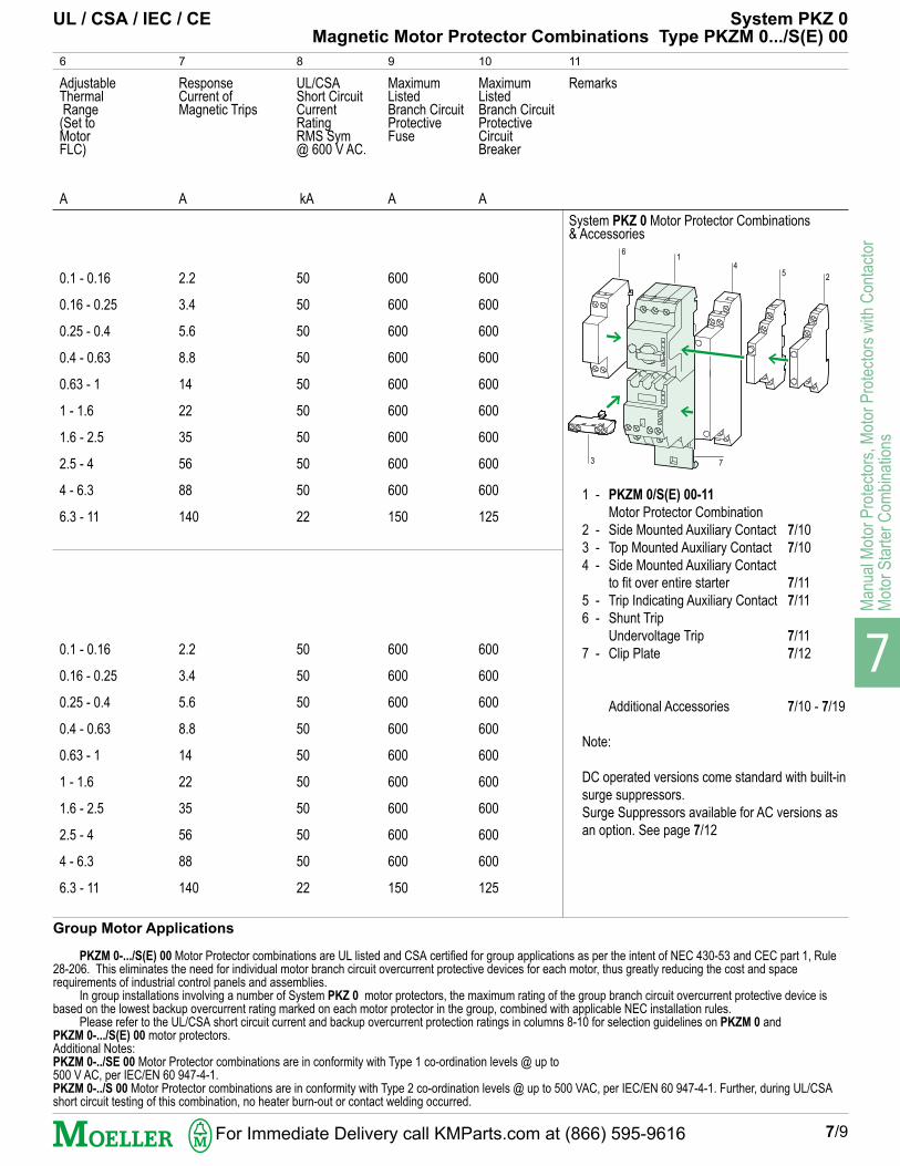
1 - PKZM 0/S(E) 00-11
Motor Protector Combination2 - Side Mounted Auxiliary Contact 7/103 - Top Mounted Auxiliary Contact 7/104 - Side Mounted Auxiliary Contact
to fit over entire starter 7/115 - Trip Indicating Auxiliary Contact 7/116 - Shunt Trip
Undervoltage Trip 7/117 - Clip Plate 7/12
Additional Accessories 7/10 - 7/19
Note:
DC operated versions come standard with built-insurge suppressors.Surge Suppressors available for AC versions asan option. See page 7/12
UL/CSAShort CircuitCurrentRatingRMS Sym@ 600 V AC.
9
MaximumListedBranch CircuitProtectiveFuse
10
MaximumListedBranch CircuitProtectiveCircuitBreaker
kA
50
50
50
50
50
50
50
50
50
22
50
50
50
50
50
50
50
50
50
22
A
600
600
600
600
600
600
600
600
600
150
600
600
600
600
600
600
600
600
600
150
A
600
600
600
600
600
600
600
600
600
125
600
600
600
600
600
600
600
600
600
125
Group Motor Applications
PKZM 0-.../S(E) 00 Motor Protector combinations are UL listed and CSA certified for group applications as per the intent of NEC 430-53 and CEC part 1, Rule28-206. This eliminates the need for individual motor branch circuit overcurrent protective devices for each motor, thus greatly reducing the cost and spacerequirements of industrial control panels and assemblies.
In group installations involving a number of System PKZ 0 motor protectors, the maximum rating of the group branch circuit overcurrent protective device isbased on the lowest backup overcurrent rating marked on each motor protector in the group, combined with applicable NEC installation rules.
Please refer to the UL/CSA short circuit current and backup overcurrent protection ratings in columns 8-10 for selection guidelines on PKZM 0 andPKZM 0-.../S(E) 00 motor protectors.Additional Notes:PKZM 0-../SE 00 Motor Protector combinations are in conformity with Type 1 co-ordination levels @ up to500 V AC, per IEC/EN 60 947-4-1.PKZM 0-../S 00 Motor Protector combinations are in conformity with Type 2 co-ordination levels @ up to 500 VAC, per IEC/EN 60 947-4-1. Further, during UL/CSAshort circuit testing of this combination, no heater burn-out or contact welding occurred.
System PKZ 0 Motor Protector Combinations& Accessories
UL / CSA / IEC / CE System PKZ 0Magnetic Motor Protector Combinations Type PKZM 0.../S(E) 00
6
3
45 2
1
7
For Immediate Delivery call KMParts.com at (866) 595-9616

7
Manual M
otor Protectors, M
otor Protectors w
ith Contactor
Motor S
tarter Com
binations
7/10
System PKZ 0- Motor ProtectorAccessories- Auxiliary Contacts
$
1
Standard Auxiliary ContactsShort Version- Side Mounted
2 3
Connection Diagram
5
Type
NHI 11-PKZ 0
NHI 12-PKZ 0
NHI 21-PKZ 0
NHI-E-11-PKZ 0
NHI-E-10-PKZ 0
NHI 2-11S-PKZ 0
Price
6
Number ofContacts
N.O. = NormallyOpen
N.C. = NormallyClosed
4
N. O.
1
1
2
1
1
2
N. C.
1
2
1
1
0
2
Remarks
7
1 - Manual Motor Protector7/6
2 - Motor Protector Combinations7/8
3 - Trip Indicating Contact7/11
The Side Mounted contacts (ShortVersion) mount on the right side ofthe protector and can be combinedwith:- Trip indicating contacts
Type AGM...- Top-Mounted contacts
Type NHI-E...but cannot be combined with thelong version contact module TypeNHI2-11S-PKZ0.
The Top-Mounted contacts TypeNHI-E... have the added benefit ofnot increasing the width or height ofthe Motor Protector when inserted.
The long version contact moduleType NHI2-11S-PKZ0mounts on the right side of thePKZM0/S(E) 00 Motor ProtectorCombination and can be combinedwith:- Top-Mounted contacts
Type NHI-E...
but cannot be combined with:- Short version contact
Modules Type NHI...- Trip indicating contacts
Type AGM...
Ordering Information:If ordered separately:- Specify Type from Column 5
Example: NHI 21-PKZ 0If ordered with device:- Add a + in front of Type
Example: + NHI 21-PKZ 0
L1 L2 L3
NHI 11
L
I >
T
1.13 1.21
1.14 1.22
L1 L2 L3
NHI 12
1.13 1.21
1.14 1.22
1.31
1.32
L1 L2 L3
NHI 21
L1 L2 L3
NHI-E-11
1.53 1.61
1.54 1.62
L1 L2 L3
NHI-E-10
1.53
1.54
L1 L2 L3
NHI 2-11S
L
I >
T
1.13 1.21 31 43
1.14 1.22 32 44
Standard Auxiliary ContactsTop Mounted
Standard Auxiliary ContactsLong Version- Side Mounted
Mounts on side of PKZM 0/S(E) 00protector combination.Features two sets of contacts:- One set actuated by Motor Protector- One set actuated by ContactorPermits differentiated signalling of thestate of Motor Protector and ContactorMain Contacts.
Clips onto top portionof PKZM 0 MotorProtector
Mounts to sideof PKZM 0 MotorProtector
AuxiliaryContactstate inrelation toMainContacts
1.13 1.21
1.14 1.22
1.33
1.34
See P
rice L
ist
S
ee P
rice L
ist
S
ee P
rice L
ist
S
ee P
rice L
ist
S
ee P
rice L
ist
S
ee P
rice L
ist
S
ee P
rice L
ist
S
ee P
rice L
ist
S
ee P
rice L
ist
S
ee P
rice L
ist
See P
rice L
ist
S
ee P
rice L
ist
S
ee P
rice L
ist
S
ee P
rice L
ist
S
ee P
rice L
ist
S
ee P
rice L
ist
S
ee P
rice L
ist
S
ee P
rice L
ist
S
ee P
rice L
ist
S
ee P
rice L
ist 1
3
2
3
For Immediate Delivery call KMParts.com at (866) 595-9616

7
Man
ual M
otor
Pro
tect
ors,
Mot
or P
rote
ctor
s w
ith C
onta
ctor
Mot
or S
tart
er C
ombi
natio
ns
7/11
1
Trip Indicating Auxiliary Contacts
2 3
Connection Diagram
5
Type
AGM 2-10-PKZ 0
AGM 2-01-PKZ 0
VHI 20-PKZ 0
A-PKZ 0 (...)
A-PKZ 0 (...)DC
U-PKZ 0 (...)
CL- PKZ 0
Price
6
Number ofContacts
N.O. = NormallyOpen
N.C. = NormallyClosed
4
N. O.
2
0
2
N. C.
0
2
0
Remarks
7
1 - Manual Motor Protector7/6
3 - Standard Auxiliary Contact7/10
- Accessories 7/13
The AGM... trip indicating contactmounts on the right side of the MotorProtector and can be combined with:Standard Auxiliary Contacts:
NHI 11-PKZ 0NHI 12-PKZ 0NHI 21-PKZ 0NHI-E-PKZ 0
It cannot be combined with the longversion auxiliary contact:
NHI 2-11S-PKZ 0
L
I >
T
"+"4.43
4.44 4.14
"I >"4.13
ON OFF
L1 L2 L3"+""I >"
TRIP "+"
L1 L2 L3"+""I >"
"+"4.31
4.32 4.22
"I >"4.21
ON OFF
L1 L2 L3"+""I >"
TRIP "+"
L1 L2 L3"+""I >"
Insert desired Voltage ratingfrom page 7/39
Shunt TripAC and DC ratings
Undervoltage TripAC ratings
C1
C2
Early-Make Auxiliary Contacts
1 - Manual Motor Protector7/6
2 - Motor Protector Combinations7/8
Voltage trip modules mount on theleft side of the main device.
A-PKZ 0 shunt trips cannot becombined with U-PKZ 0 undervoltagetrips. The DC version is rated forshort time duty: Max. 5 sec.
U-PKZ 0 undervoltage trips cannotbe combined with A-PKZ 0 shunttrips. Can be used in conjunctionwith the Motor Protector PKZM 0 andVHI early-make contacts to provideEmergency-Stop functions.
System PKZ 0- Motor ProtectorAccessories- Auxiliary Contacts, Voltage Trips
Mounts to side of PKZM 0 MotorProtector. Provides a differentiatedtrip signal:"+" : These contacts actuate underall trip conditions."I >" : These contacts actuate only
under short circuit trip conditions.Also comes with red short circuit tripindicator which can be resetmanually.
AuxiliaryContactstate inrelation toMainContacts
Clips onto top portion of PKZM 0 MotorProtector. Ideally used in combinationwith the undervoltage trip module inEmergency-Stop circuits
Voltage trips
Ordering Information:- If ordered separately: Specify Type from Column 5. Example: U-PKZ 0 (120V, 60Hz)
- If ordered with device: Add a + in front of Type: Example: + U-PKZ 0 (120V, 60 Hz)
D1
D2
U <
Fuseless Current LimiterL
I >>
T
Used to increase the shortcircuit rating of Motor Protec-tors and Motor ProtectorCombinations. Mounts beneathor next to PKZM 0 MotorProtector. S
ee P
rice L
ist
S
ee P
rice L
ist
S
ee P
rice L
ist
S
ee P
rice L
ist
S
ee P
rice L
ist
S
ee P
rice L
ist
S
ee P
rice L
ist
S
ee P
rice L
ist
S
ee P
rice L
ist
See P
rice L
ist
S
ee P
rice L
ist
S
ee P
rice L
ist
S
ee P
rice L
ist
S
ee P
rice L
ist
S
ee P
rice L
ist
S
ee P
rice L
ist
S
ee P
rice L
ist
S
ee P
rice L
ist 1
3
1
2
For Immediate Delivery call KMParts.com at (866) 595-9616

7
Manual M
otor Protectors, M
otor Protectors w
ith Contactor
Motor S
tarter Com
binations
7/12
1
Magnetic Contactor Module
2 3
Connection Diagram
200 V
2
2
2
2
2
2
2
2
Voltage Range (50,60Hz):
24 - 48 V AC
110 - 250 V AC
24 - 48 V AC
110 - 250 V AC
380 - 415 V AC
4
Number of Contacts
N.O. = NormallyOpen
N.C. = NormallyClosed
N. O.
1
2
2
1
1
2
2
1
1
N. C.
1
–
–
1
1
–
–
1
1
5
For Use With:
230 V
3
3
3
3
3
3
3
3
460 V
5
5
5
5
5
5
5
5
575 V
5
5
5
5
5
5
5
5
PKZM 0
PKZM 0
PKZM 0
PKZM 0
PKZM 0
PKZM 0
PKZM 0
PKZM 0
S(E)00-...-PKZ 0
S(E)00-...-PKZ 0
S(E)00-...-PKZ 0
S(E)00-...-PKZ 0
S(E)00-...-PKZ 0
S(E)00-PKZ 0 (...)HI 11-S/EZ-PKZ 0
S(E)00-PKZ 0 (...)PKZM 0-../S(E)00
S(E)00 + EZ-PKZ 0
Surge Suppressorsfor AC Contactor Coils
Base for separate mounting
Mechanical Interlock
A1
A2
A1
A2
43 31
44 32
System PKZ 0- Motor ProtectorContactors and Accessories, Auxiliary Contacts, Surge Suppressors
High Capacity Magnetic Contactor Modulewith Current Limiting Contact Assembly
Plug-fit into load side
of Motor Protector
UL/CSAMaximum3 Phase HP Rating @:
(Single phase ratings: page 7/44)
Auxiliary contact module
I >>
T
13
14 22
A1
A2
21
T
13 23
14 24
A1
A2
I >>
T
13 21
2214A2
A1
T
13 23
14 24
A1
A2
For Immediate Delivery call KMParts.com at (866) 595-9616

7
Man
ual M
otor
Pro
tect
ors,
Mot
or P
rote
ctor
s w
ith C
onta
ctor
Mot
or S
tart
er C
ombi
natio
ns
7/13
6
Type
SE00-11-PKZ 0 (...)
SE00-20-PKZ 0 (...)
SE00-20-PKZ 0 (...V DC)
SE00-11-PKZ 0 (...V DC)
S00-11-PKZ 0 (...)
S00-20-PKZ 0 (...)
S00-20-PKZ 0 (...V DC)
S00-11-PKZ 0 (...V DC)
RC SPKZ 0 48
RC SPKZ 0 250
VG SPKZ 48
VG SPKZ 250
VG SPKZ 415
EZ-PKZ 0
MV-PKZ 0
HI11-S/EZ-PKZ 0
Price
7 8
Notes
9
Remarks
SE 00 and S 00 contactors are onlysuitable for use with PKZM 0 protectors.
The Contactors are designed to plug intothe load side of the PKZM 0 MotorProtector to form a compact andcontoured fit.A clip plate (see figure at right), ontowhich the combination is mounted, is anecessary part of the assembly and mustbe ordered separately if the MotorProtector combination is not purchasedcomplete as shown on page 7/8.
S(E) 00 contactors can also be Individu-ally mounted using the EZ-PKZ 0mounting base. Contactors so mountedcan also be equipped with a side-mounted auxiliary contact module TypeHI11-S/EZ-PKZ 0. (See below).
The S 00 contactor is identical to theSE 00 except for the built-in currentlimiting contact assembly, which makes itsuitable for “Type 2” co-ordination levelsper IEC/EN 60 947 and no weldingperformance in combination with thePKZM 0 Motor Protector.
DC rated contactor coils are suppliedstandard with built-in surge suppressors.
Coil Voltage: Circuit Diagram:
12 V DC24 V DC48 V DC60 V DC
110 V DC220 V DC
SE 00 and S 00 contactors can beindividually or separately mounted usingthe EZ-PKZ 0 mounting base. The basecan also be mounted on DIN rail (on railsof 7.5 mm or 15 mm heights).
The MV-PKZ 0 can be used to mechani-cally interlock two S(E) 00 contactors e.g.to build reversing starter combinations.
Cannot be combined with:PKZM 0-../S(E) 00 equipped withNHI-...-PKZ 0 and/or AGM-...-PKZ 0.
1 - PKZM 0 Motor Protector 7/62 - Side-mounted, long version
Auxiliary Contact 7/103 - Clip Plate 7/13
- Additional Accessories 7/14
Ordering Information:Specify Type from Column 6.Example: MV-PKZ 0
Insert desired coil voltage where specified.Example: SE00-11-PKZ 0 (120V, 60Hz)
S00-20- PKZ 0 (24V DC)
Specify CoilVoltagefrom page 7/39when ordering
System PKZ 0- Motor Protector Contactors and Accessories, Auxiliary Contacts, Surge Suppressors
Specify CoilVoltagefrom page 7/39when ordering
13
2
See P
rice L
ist
S
ee P
rice L
ist
S
ee P
rice L
ist
S
ee P
rice L
ist
S
ee P
rice L
ist
S
ee P
rice L
ist
S
ee P
rice L
ist
S
ee P
rice L
ist
S
ee P
rice L
ist
S
ee P
rice L
ist
See P
rice L
ist
S
ee P
rice L
ist
S
ee P
rice L
ist
S
ee P
rice L
ist
S
ee P
rice L
ist
S
ee P
rice L
ist
S
ee P
rice L
ist
S
ee P
rice L
ist
S
ee P
rice L
ist
S
ee P
rice L
ist
For Immediate Delivery call KMParts.com at (866) 595-9616

7
Manual M
otor Protectors, M
otor Protectors w
ith Contactor
Motor S
tarter Com
binations
7/14
System PKZ 0- Motor ProtectorInsulated Enclosures, Housings, Padlocking provisions
1
Insulated Enclosures for surface mounting
2 3
Notes
6
Type
CI-PKZ 0
CI-PKZ 0-G
CI-PKZ 0-GR
CI-PKZ 0-GV
CI-PKZ 0-GRV
SVB-PKZ 0-CI
CI23X-125-NA
E-PKZ 0
E-PKZ 0-G
E-PKZ 0-GR
SVB-PKZ 0-E
Price
7
For Use With
4
PKZM 0-..+NHI or U or A,+L-PKZ 0(Max. 2 lights)
PKZM 0-...,+NHI+NHI-E orU+NHI-E or A+NHI-E,+L-PKZ 0(Max. 2 lights)
PKZM 0-...+VHI...+ U...
PKZM 0-...+VHI...+ U...
CI-PKZ 0-G(R)(V)
PKZM 0-.../S(E)00+NHI or NHI...S+NHI-E, +U or A+(R)H+L PKZ 0(MAX. 2 lights)
PKZM 0-...,+NHI or U or A,+L-PKZ 0 (Max.2 lights)
PKZM 0-...,+NHI+NHI-E orU+NHI-E or A+NHI-E,+AGM or U+NHI-E orA+NHI-E, +L-PKZ 0
E-PKZ 0-G(R)
Remarks
5
Degree ofProtection
Cover with openingdimensioned to accommo-date front of MotorProtector
With black/gray handle
With red/yellow handlefor use in Emergency-Stopcircuits.
With black/gray handle
With red/yellow handle foruse in Emergency-Stopcircuits.
Padlocking assemblyaccommodating up to 3padlocks with a haspthickness of 3 - 6 mm
Suitable for coverinterlocking handle(R)H-PKZ 0 (IP 65).
Cover with openingdimensioned to accommo-date front of MotorProtector
With black/gray rotaryhandle
With red/yellow rotaryhandle for use inEmergency-Stop circuits
Padlocking accessory toaccommodate up to 3padlocks with a haspthickness of 3 - 6 mm
IP 40UL/NEMA 1
IP 55UL/NEMA 12
IP 55UL/NEMA 12
IP 55UL/NEMA 12
IP 55UL/NEMA 12
IP 65UL/NEMA 121)
Front IP 40
Front IP 55
Front IP 55
Includes ground terminalconnection, 2 PG 16 cableentry knockouts, top andbottom
Includes ground terminalconnection, 2 PG 16 cableentry knockouts, top andbottom
Padlockable in the OFFposition of the PKZM 0Manual Motor Protector
Mounting depth 125 mm,additional M3-CI23mounting plate required
Includes ground terminalconnection, 2 PG 16 cableentry knockouts, top andbottom
Padlockable in the OFFposition of the PKZM 0Manual Motor Protector
Insulated Housings for cavity mounting
For Motor Protector
For Motor Protector with early-make contacts
For Motor Protector enclosures
For Motor Protector Combinations
1) UL Type 12 currently under submittal
Ordering Information:Specify Type from Column 6.Example: CI-PKZ 0-G
See P
rice L
ist
S
ee P
rice L
ist
S
ee P
rice L
ist
S
ee P
rice L
ist
S
ee P
rice L
ist
S
ee P
rice L
ist
S
ee P
rice L
ist
S
ee P
rice L
ist
S
ee P
rice L
ist
See P
rice L
ist
S
ee P
rice L
ist
S
ee P
rice L
ist
S
ee P
rice L
ist
S
ee P
rice L
ist
S
ee P
rice L
ist
S
ee P
rice L
ist
S
ee P
rice L
ist
S
ee P
rice L
ist
For Immediate Delivery call KMParts.com at (866) 595-9616

7
Man
ual M
otor
Pro
tect
ors,
Mot
or P
rote
ctor
s w
ith C
onta
ctor
Mot
or S
tart
er C
ombi
natio
ns
System PKZ 0- Motor ProtectorAccessories- Clip plates, Handles, Indicating Lights
7/15
1
Clip Plate
2
Notes
3
Type
C-PKZ 0
H-PKZ 0
RH-PKZ 0
HSOV-PKZ 0
AK-PKZ 0
PL-PKZ 0
L-PKZ 0 (230V)
L-PKZ 0 (400V)
L-PKZ 0 (500V)
L-PKZ 0-GN (230V)
L-PKZ 0-GN (400V)
L-PKZ 0-GN (500V)
L-PKZ 0-RT (230V)
L-PKZ 0-RT (400V)
L-PKZ 0-RT (500V)
Price
4
Always necessary when combining a PKZM 0 manual protector and a S(E) 00magnetic contactor to create a magnetic Motor Protector Combination.Can be either panel mounted with screws or DIN rail mounted using one 15 mmheight rail or two 7.5 or 15 mm height rails. DIN rails must conform to EN 50 022-35.
For use as Main Switch. Door/Cover interlocked when switch is in the ON position.Color: Black with On/Off and "+" (Trip) switch positions, lockable in OFF positionusing three 4 - 8 mm padlocks. Can also be modified to be lockable in the ONposition.
For use as Main Switch with Emergency-Stop function. Door/Cover interlockingfeature. Color: Red/yellow with On/Off and "+" (Trip) switch positions, lockable inOFF position using three 4 - 8 mm padlocks.
Simpler mechanism, without any door/cover interlocking or padlocking capability.Color: Black, with On/Off and "+" (Trip) switch positions.
Replaces standard PKZM 0 knob handle with a padlockable version. Accommodates1/4” padlocks (range: 3 – 6.35 mm). Padlockable in OFF position.
To prevent unauthorized access to the Motor FLC thermal trip dial setting and theTest-to-Trip function. Uses conventional lead seal.
For CI23X-..., CI-PKZ 0-..., E-PKZ 0-... Enclosures and Housings
Color: White Voltages: 110 - 230 V
230 - 400 V
415 - 500 V
Color: Green Voltages: 110 - 230 V
230 - 400 V
415 - 500 V
Color: Red Voltages: 110 - 230 V
230 - 400 V
415 - 500 V
Indicator Lights
Door Coupling Handles UL/NEMA 12 / IEC IP 651)
1/4” Padlockable Knob for Manual Protector
Drive dog and A-H-PKZ 0 extension shaft supplied with all door coupling handles. The extensionshaft can be cut to any required length to accommodate mounting depths of 100 – 240 mm.
Tamper sealing Cover
Ordering Information:Specify Type from Column 3.Example: AK-PKZ 0
See P
rice L
ist
S
ee P
rice L
ist
S
ee P
rice L
ist
S
ee P
rice L
ist
S
ee P
rice L
ist
S
ee P
rice L
ist
S
ee P
rice L
ist
S
ee P
rice L
ist
S
ee P
rice L
ist
S
ee P
rice L
ist
See P
rice L
ist
S
ee P
rice L
ist
S
ee P
rice L
ist
S
ee P
rice L
ist
S
ee P
rice L
ist
S
ee P
rice L
ist
S
ee P
rice L
ist
S
ee P
rice L
ist
S
ee P
rice L
ist
S
ee P
rice L
ist
1) UL Type 12 currently under submittal
For Immediate Delivery call KMParts.com at (866) 595-9616

7
Manual M
otor Protectors, M
otor Protectors w
ith Contactor
Motor S
tarter Com
binations
7/16
System PKZ 0- Motor ProtectorWiring Accessories
1
Three-Phase Feeder Bus ConnectorsReduces mounting space and wiring time by eliminating daisy-chain wiring.
Can be joined to accommodate more units.
Finger-Safe!
2
Notes
6
Type
B3.0/2-PKZ 0
B3.0/4-PKZ 0
B3.1/2-PKZ 0
B3.1/3-PKZ 0
B3.1/4-PKZ 0
B3.1/5-PKZ 0
B3.2/2-PKZ 0
B3.2/4-PKZ 0
H-B3-PKZ 0
BK25/3-PKZ 0
Price
7
Number ofMotorProtectors
3
2
4
2
3
4
5
2
4
UnitWidthavailableperMotorProtector
5
For Motor Protector and Motor ProtectorCombinations without side-mounted auxiliarycontacts or voltage trips.
For Motor Protector and Motor ProtectorCombinations each with one side-mountedauxiliary contact or trip-indicating contactmodule, or a single voltage trip.
For Motor Protector and Motor ProtectorCombinations each having one auxiliary contactand trip-indicating auxiliary contact modulemounted on the right, or a voltage trip mountedon the left, or for Motor Protector Combinationshaving a long NHI 2-11S-PKZ 0 standardauxiliary contact mounted on the right.
Finger-safe covers which slip over unusedterminals of a three-phase feeder bus connector toprotect against accidental contact.
Incoming supply terminal to feed bus connectors.Finger-safe design. Maximum Ampacity: 63 APermissible Conductor Range:AWG 10...4, Cu Only
mm
45
45
45 + 9
45 + 9
45 + 9
45 + 9
45 + 18
45 + 18
Protective Shroud for Unused Terminals
Connector Feeder Terminal
Connec-torLength
4
mm
90
180
99
153
207
261
108
234
Ordering Information:Specify Type from Column 6. Example: B3.1/2-PKZ 0
See P
rice L
ist
S
ee P
rice L
ist
S
ee P
rice L
ist
S
ee P
rice L
ist
S
ee P
rice L
ist
S
ee P
rice L
ist
S
ee P
rice L
ist
S
ee P
rice L
ist
See P
rice L
ist
S
ee P
rice L
ist
S
ee P
rice L
ist
S
ee P
rice L
ist
S
ee P
rice L
ist
S
ee P
rice L
ist
S
ee P
rice L
ist
S
ee P
rice L
ist
For Immediate Delivery call KMParts.com at (866) 595-9616

7
Man
ual M
otor
Pro
tect
ors,
Mot
or P
rote
ctor
s w
ith C
onta
ctor
Mot
or S
tart
er C
ombi
natio
ns
7/17
1
Control Panel Bus Bar Adapters, 3-Pole
2
For use with
6
Type
AD 25/5-1
AD 25/5-2
AD 25/5-144
AD 25/10-1
AD 25/10-2
AD 25/10-144
AD-E
Price
7
MaximumRatedCurrent
3
Amps
25
25
25
25
25
25
AdapterWidth
5
PKZM 0-... orPKZM 0-.../S(E)00+ AGM or NHI
2 x PKZM 0-... or2 x PKZM 0-.../S(E) 00+ AGM or NHI, or1 x PKZM 0-...+ 2 x EZ-PKZ 0 + MV-PKZ 0
2 x PKZM 0-... or2 x PKZM 0-.../S(E) 00+ AGM or NHI, or1 x PKZM 0-...+ 2 x EZ-PKZ 0 + MV-PKZ 0+ AGM or NHI
PKZM 0-... orPKZM 0-.../S(E) 00+ AGM or NHI
2 x PKZM 0-... or2 x PKZM 0-.../S(E) 00+ AGM or NHI, or1 x PKZM 0-...+ 2 x EZ-PKZ 0 + MV-PKZ 0
2 x PKZM 0-... or2 x PKZM 0-.../S(E) 00+ AGM or NHI, or1 x PKZM 0-...+ 2 x EZ-PKZ 0 + MV-PKZ 0+ AGM or NHI
Push-fit strip, can be fitted onto AD...to extend mounting width
mm
54
108
144
54
108
144
9
Adapter Extension
AdapterSupplyleads
4
AWG
10
10
10
10
10
10
System PKZ 0- Motor ProtectorWiring Accessories
For mounting in industrial control panels on Cu 20 x 5 mm busbar arrangementswith 60 mm phase separation . The back of the adapter connects onto the bus.Components are mounted on top of the adapter and wired to the supply leads.All assembly is done under de-energized (Power OFF) conditions.
Same as above except for mounting on Cu 30 x 10 and 20 x 10 mm busbar arrangements with 60 mmphase separation.
Ordering Information:Specify Type from Column 6. Example: AD 25/10-1
See P
rice L
ist
S
ee P
rice L
ist
S
ee P
rice L
ist
S
ee P
rice L
ist
S
ee P
rice L
ist
S
ee P
rice L
ist
S
ee P
rice L
ist
S
ee P
rice L
ist
See P
rice L
ist
S
ee P
rice L
ist
S
ee P
rice L
ist
S
ee P
rice L
ist
S
ee P
rice L
ist
S
ee P
rice L
ist
S
ee P
rice L
ist
S
ee P
rice L
ist
For Immediate Delivery call KMParts.com at (866) 595-9616

7
Manual M
otor Protectors, M
otor Protectors w
ith Contactor
Motor S
tarter Com
binations
1 2
For Use WithPKZM 0 Motor Protectors+ DIL...M Magnetic Contactors
(Refer to Section 3 forinfo on Type DIL...Mcontactors.)
4
MVS KitType
MVS-D4
MVS-D5
MVS-D11
MVS-D11
MVS-W4
MVS-W5MV
MVS-W11MV
MVS-W11MV
MVS-S5
MVS-S7
MVS-S11
MVS-C45-S
Price
5
Remarks
6
PKZM 0 + DIL (E)EM
PKZM 0 + DIL 00(A)M
PKZM 0 + DIL 0M
PKZM 0 + DIL 0AM
PKZM 0 + DIUL (E)EM/21/MV
PKZM 0 + DIUL 00(A)M/11/MV
PKZM 0 + DIUL 0M/11/MV
PKZM 0 + DIUL 0AM/11/MV
PKZM 0 + DIL EM/EEM +DIL ET 11-30-A
PKZM 0 + DIL 00AM/00M + ETR 4-51-A
PKZM 0 + DIL 0M/00AM+ETR 4-51-A
PKZM 0-.../SE 00
PKZM 0-.../S 00
Includes a mounting plate and finger-safe wiring harness to accommodateFVNR motor starter combinationsconsisting of PKZM 0 Motor Protec-tors and DIL...M Magnetic Contactorsin various HP sizes.UL listed/CSA certified for groupinstallations and high fault short circuitcurrent ratings (see page 7/19) inassociation with Moeller Electriccomponents.
Includes a mounting plate and finger-safe wiring harnesses to accommo-date FVR motor starter combinationsconsisting of PKZM 0 Motor Protec-tors and DIL...M mechanicallyinterlocked Magnetic Contactors invarious HP sizes.UL listed/CSA certified for groupinstallations and high fault short circuitcurrent ratings (see page 7/19) inassociation with Moeller Electriccomponents.
Includes a mounting plate and finger-safe wiring harnesses to accommo-date Star-Delta motor starter combina-tions consisting of PKZM 0 MotorProtectors, electronic timing relays andDIL...M Magnetic Contactors in variousHP sizes.UL listed/CSA certified for groupinstallations and high fault short circuitcurrent ratings (see page 7/19) inassociation with Moeller Electriccomponents.
Mounting Plate to combinePKZM 0-.../S(E) 00 Motor ProtectorCombinations with other MVS starters.Also allows feed using bus barconnectors (page 7/16).
7/18
Full Voltage, Non-Reversing Starter Combinations
Star-Delta Starter Combinations
Accommodates Mechanically Interlocked Contactors
Notes:Control Circuit Voltage
The MVS System wiring harnesses are designed to accommodate DIL (E)EM contactors that areeither AC or DC energized and DIL...M contactors that are AC energized only.
Surge Suppressors for DIL...M contactors
The following surge suppressors can be used with DIL...M contactors mounted on MVS mtg. plates:RC B DIL 250 (RC filter), VG B DIL 250 (Varistor suppressor) and FD B-DIL (diode suppressor)
Refer to Section 3 for more information on DIL (E)EM and DIL M contactors.
460 V 575 V
5 5
71/2 10
10 15
15 20
5 5
71/2 10
10 15
15 20
71/2 10
10 15
15 20
UL/CSAMaximum3 Phase HPRating @:
Open Transition
System PKZ 0- Motor ProtectorMVS Mounting and Wiring Accessory Kits for Motor Starter Combinations
For PKZM 0 Motor Protector Combinations
Ordering Information:Specify Type from Column 4.Example: MVS-D5
3
See P
rice L
ist
S
ee P
rice L
ist
S
ee P
rice L
ist
S
ee P
rice L
ist
S
ee P
rice L
ist
S
ee P
rice L
ist
S
ee P
rice L
ist
S
ee P
rice L
ist
See P
rice L
ist
S
ee P
rice L
ist
S
ee P
rice L
ist
S
ee P
rice L
ist
S
ee P
rice L
ist
S
ee P
rice L
ist
S
ee P
rice L
ist
S
ee P
rice L
ist
For Immediate Delivery call KMParts.com at (866) 595-9616

7
Man
ual M
otor
Pro
tect
ors,
Mot
or P
rote
ctor
s w
ith C
onta
ctor
Mot
or S
tart
er C
ombi
natio
ns
7/19
Installation Instructions
UL/CSA Short Circuit Current / NEC Group Protection Ratings
MVS System used in association with PKZM 0 Motor Protectors, DIL...M Magnetic Contactors and Listed BranchCircuit Overcurrent Protective Devices
RMS Short Circuit Listed Group
Current Rating Protection Back-up
@ 600 V AC Device
kA Fuse Breaker
PKZM 0-6.3 + DIL....M + MVS 50 600 A 600 A
PKZM 0-10 + DIL...M + MVS 22 150 A 125 A
PKZM 0-16, 20, 25 + DIL...M + MVS 10 150A 125 A
MVS System
System PKZ 0- Motor ProtectorMVS Mounting and Wiring Accessories for Motor Starter Combinations
The MVS system consists of mounting plates and wiring harnesses designed to combine PKZM 0 Motor Protectors and DIL...M
Magnetic Contactors in various Motor Starter configurations.MVS Motor Starter Combinations are UL Listed and CSA Certified for group installations per the intent of NEC 430-53 and are alsorated for high fault current ratings in association with listed upstream protective circuit breakers or fuses.The MVS mounting and wiring system greatly cuts down the amount of mounting and wiring assembly time normally associated withmotor starters and is thus ideally suited for use in industrial control panels.
Full Voltage Non-Reversing Combinations: MVS-D...
Full Voltage Reversing Combinations: MVS-W...(MV)Star-Delta Combinations MVS-S...
The MVS System Mounting plates are equipped with DIN Rails onto which PKZM 0 Motor Protector and DIL...M Magnetic Contactorsare securely fastened. Each MVS type comes with its own set of wiring harnesses to accommodate a number of starter configurationssuch as Full Voltage Non-Reversing and Full Voltage Reversing combinations. Once the wiring harness is in place it will provide afinger-safe connection between the Motor Protector and Contactor(s). One size screwdriver is the only tool required to complete theassembly. The mounting plate itself can either be panel mounted using screws or snapped onto a 35 mm DIN rail (EN 50 022) forquicker assembly. Depending on the starter type, assembly and wiring time is reduced by more than 50% over conventional methods.In addition to the time saving, the MVS System kits will further lower costs by reducing overall panel space requirements.
For Immediate Delivery call KMParts.com at (866) 595-9616

7
Manual M
otor Protectors, M
otor Protectors w
ith Contactor
Motor S
tarter Com
binations
7/20
System PKZ 2 refers to all of thecomponents and accessories whichmake up the line of PKZ 2 Motor Protectors.It is a modular system, with ample flexibilityand comprehensive ratings to accommodate a broadrange of industrial control motor switching and protectionrequirements.System PKZ 2 components are in compliance with all pertinentinternational and domestic standards and can be installedworld-wide.Maximum ratings: 42 Amps, 600 V AC
Overview UL/CSA; IEC/EN 60 947; CESystem PKZ 2 Manual Motor Protector and Magnetic Motor Protector Combinations
For Immediate Delivery call KMParts.com at (866) 595-9616

7
Man
ual M
otor
Pro
tect
ors,
Mot
or P
rote
ctor
s w
ith C
onta
ctor
Mot
or S
tart
er C
ombi
natio
ns
OverviewSystem PKZ 2
7/21
Manual Motor ProtectorThermal-Magnetic Motor Protector
Adjustable Thermal & Magnetic Trips
Ambient Compensated, Phase failure sensitive
Rated up to 42 Amps
Maximum 3 Phase HP rating: 30 @ 460/ 575 V AC
UL Listed for Group installations per NEC 430-53
CSA Certified for Group installations per CEC Part 1, 28-206
High Short Circuit Rating: Up to 65 kA/42 kA @ 480/600 V AC
UL Listed, CSA Certified, in Conformity to IEC/EN 60 947
CE Marked
Type: PKZ 2/ZM-...
1
Corrosion Resistant EnclosuresCorrosion resistant enclosures made of high industrial grade
insulating material to house PKZ 2/ZM Manual Motor
Protectors and PKZ 2/ZM-.../S Magnetic Motor Protector
Combinations.
UL/NEMA 12, IEC IP 40 and 54 Environmental ratings with
cover interlocked operating handle.
Type: CI...
3
Auxiliary Contact ModulesSignals ON/OFF status of PKZ 2/ZM Motor Protector and
PKZ 2/ZM-.../S Motor Protector + Contactor combination.
Trip indicating contacts which differentiate between overload
and short circuit tripping.
Type: NHI-...-PKZ 2, AGM-...-PKZ 2
10
Door/Cover Mounted HandleRated IP 65/ NEMA/UL 12, 3R.
3 Positions- ON, OFF, Tripped.
Door interlocking feature and padlockable with up to
3 padlocks.
Plug-in extension shaft to accommodate various mounting
depths.
Black, or Red/Yellow for E-Stop function
Type: (R)H-PKZ 2
9
Magnetic Contactor ModuleAC or 24 V DC operated versions.
AC Supplied with 1 N.O./1N.C. or 2 N.O. contacts.
Plugs into the load side of the PKZ 2/ZM protector or can be
separately mounted.
Can be equipped with 4th (Neutral) Pole.
Rated 20 kW @ 400/415 V AC.
IEC 60 947-4-1 rated for Type 1 co-ordination.
CE Marked. For IEC/EN applications.
Type: SE1A/...-PKZ 2, SE1A-G-...-PKZ 2
(Consult Moeller Electric for further info)
6
High Capacity MagneticContactor Module
Internal current limitation feature to increase short circuit
current rating and self-protection characteristics.
AC or 24 V DC operated versions.
AC Supplied with 1 N.O./1N.C. or 2 N.O. contacts.
Plugs into the load side of the PKZ 2/ZM protector to create
PKZ 2/ZM-.../S Magnetic Motor Protector combination.
In association with PKZ 2/ZM:
Maximum 3 Phase HP rating: 30 @ 460/ 575 V AC
UL Listed for Group installations per NEC 430-53
CSA Certified for Group installations per CEC Part 1, 28-206
High Short Circuit Rating: Up to 65 kA/42 kA @ 480/600 V AC
Rated 20 kW @ 400/415 V AC.
IEC 60 947-4-1 rated for Type 2 co-ordination.
UL Listed, CSA Certified, in conformity with IEC/EN 60 947
CE Marked
Type: S-PKZ 2
7
Voltage trip ModulesUndervoltage trip modules:
- With Early-Make auxiliary contacts
- With Drop-Off delay and Early-Make auxiliary contacts
Shunt trip module
Mounts on the side of the PKZ 2/ZM Motor Protector.
Type: U-PKZ 2, UHI 20-PKZ 2, UVHI-PKZ 2, A-PKZ 0
4
Mounting/WiringClip plate, onto which combinations of the PKZ 2/ZM-...
Motor Protector and S-PKZ 2 Magnetic contactors are
mounted to form Motor Protector Combinations.
Suitable for DIN rail mounting (EN 50 022). Can also be panel
mounted with screws.
Other Mounting/Wiring Hardware:
- Adapters for direct busbar feeds in control panels.
- 3 Phase Bus connectors to eliminate the need for daisy-
chain wiring of motor protector combinations.
Type: C-PKZ 2
2
Remote Control DriveElectrically turns PKZ 2/ZM Motor Protector ON and OFF
Electrically resets PKZ 2/ZM Motor Protector from Tripped
position.
Available in both AC and DC models.
Has HAND and AUTO settings for maximum flexibility.
HAND and AUTO positions are also signalled with an auxiliary
contact.
HAND position can be padlocked OFF.
Type RS-PKZ 2 can be directly energized by a 24 V DC
output from a PLC.
Type: RE-PKZ 2, RS-PKZ 2
5
Current Limiter ModuleFuseless, current limiting set of contacts housed in a module.
Increases short circuit current rating of the PKZ 2/ZM up to
100 kA @ 500 V AC. For IEC/EN applications.
Plugs directly into the PKZ 2/ZM or is separately mounted.
Type: CL-PKZ 2
8
For Immediate Delivery call KMParts.com at (866) 595-9616

7
Manual M
otor Protectors, M
otor Protectors w
ith Contactor
Motor S
tarter Com
binations
Trip IndicatingContacts
AGM 2-11-PKZ 2
●
●
●
●
●
●
Type
PKZ 2/ZM-...
PKZ 2/ZM-.../S
7/22
Degree ofProtection
Type 1GeneralPurpose
Type 12
Type 1GeneralPurpose
Type 12
Open Devices, Enclosures
Type
–
CS 3-PKZ 2
CI 19EE-PKZ2-NA
–
S1 GK-PKZ 2
CI 43-PKZ 2
AccessoriesThe possible combinations of openand enclosed motor protectors withvarious accessories is indicated bya dot ● in each shaded row.
Surface Mounting Enclosures
System PKZ 2- Motor ProtectorOverview of Combinations
Motor Protector Combination
with
High
Capacity
Contactor
Manual Motor Protector
without
Contactor
Surface Mounting Enclosures
Standard AuxiliaryContacts
NHI 11 S-PKZ 2NHI 22 S-PKZ 2NHI 2-11 S-PKZ 2
–
–
–
●
●
●
Standard AuxiliaryContacts
NHI 11-PKZ 2NHI 22-PKZ 2
●
●
●
● or
● or
● or
Steel
Insulating material
Steel
Insulating material
For Immediate Delivery call KMParts.com at (866) 595-9616

7
Man
ual M
otor
Pro
tect
ors,
Mot
or P
rote
ctor
s w
ith C
onta
ctor
Mot
or S
tart
er C
ombi
natio
ns
7/23
UndervoltageTrip
U-PKZ 2UVHI-PKZ 2
● or
● or
● or
● or
● or
● or
System PKZ 2- Motor ProtectorOverview of Combinations
Door MountingHandle
H-PKZ 2RH-PKZ 2
–
–
●
–
●
●
Shunt Trip
A-PKZ 2
●
●
●
●
●
●
U-HI 20-PKZ 2
● or
● or
● or
● or
● or
● or
Remote Drive
RE-PKZ 2RS-PKZ 2
●
● or
–
●
–
–
For Immediate Delivery call KMParts.com at (866) 595-9616

7
Manual M
otor Protectors, M
otor Protectors w
ith Contactor
Motor S
tarter Com
binations
1
7/24
2 4
Type
460 V
1/2
3/4
1
2
3
5
10
20
20
30
1/2
3/4
1
2
3
5
10
20
20
30
230 V
1/2
1
11/2
3
5
71/2
10
15
1/2
1
11/2
3
5
71/2
10
15
PKZ 2/ZM-0.6
PKZ 2/ZM-1
PKZ 2/ZM-1.6
PKZ 2/ZM-2.4
PKZ 2/ZM-4
PKZ 2/ZM-6
PKZ 2/ZM-10
PKZ 2/ZM-16
PKZ 2/ZM-25
PKZ 2/ZM-32
PKZ 2/ZM-40
PKZ 2/ZM-0.6/S (...)
PKZ 2/ZM-1/S (...)
PKZ 2/ZM-1.6/S (...)
PKZ 2/ZM-2.4/S (...)
PKZ 2/ZM-4/S (...)
PKZ 2/ZM-6/S (...)
PKZ 2/ZM-10/S (...)
PKZ 2/ZM-16/S (...)
PKZ 2/ZM-25/S (...)
PKZ 2/ZM-32/S (...)
PKZ 2/ZM-40/S (...)
Price
5
The PKZ 2/ZM-... is a 3 phase thermal-magnetic motor protective deviceincorporating adjustable bimetal trips for motor overload protection and magnetictrips to de-energize the motor circuit in case of a short circuit. The PKZ 2/ZM-.../S
is a combination of the PKZ 2/ZM-... manual motor protector and the S-PKZ 2
High Capacity magnetic contactor.The PKZ 2/ZM-... and the PKZ 2/ZM-.../S are UL listed and CSA certified as
HP rated motor controllers which provide motor running overload protection. Inaddition, they are UL listed and CSA certified for group applications as per NEC430-53(c) and CEC part 1, Rule 28-206. This means that a group of motors, eachprotected and controlled by a PKZ 2/ZM-... or a PKZ 2/ZM-.../S, can be combinedunder a single branch circuit short circuit and ground fault protective device, themaximum rating of which is marked on each PKZ 2 motor protector. (See columns7-9 for UL/CSA short circuit current and backup overcurrent protection ratings.)
Features:■ Ratings: 42 Amp, 600 V AC - 30 HP/460 V, 30 HP/575 V max.■ Approved for world markets = UL, CSA, IEC/EN 60 947, CE Marked■ Conformity with IEC/EN 60 947 “Type 2” co-ordination levels■ Phase failure sensitive.■ Adjustable thermal trips set to motor FLC. Ambient compensated.■ Adjustable magnetic trips.■ Open or door mounted handle, padlockable, with 3 position indication
(ON, OFF, Trip). See Accessories on page 7/37■ 'Finger Safe' construction.■ 35 mm DIN rail or panel mounting.
Specify Coil Voltagefrom page 7/40 when ordering (...)
575 V
1/2
1
11/2
3
5
71/2
10
25
30
30
1/2
1
11/2
3
5
71/2
10
25
30
30
In this range select Motor Protector inaccordance withthe MotornameplateFull Load Current.
UL/CSAMaximum3 Phase HP Rating @:
(Single phase ratings: page 7/53)
Circuit Diagram
In this range select Motor Protector inaccordance withthe MotornameplateFull Load Current.
200 V
1/2
1
11/2
2
3
71/2
10
10
1/2
1
11/2
2
3
71/2
10
10
Manual Motor Protectors
L
I >
T
Magnetic Motor Protector Combinationwith High Capacity ContactorUL/CSA Group installationsIEC/EN 60 947-4-1 “Type 2”co-ordination level
Ordering Information: Specify Type from column 4 and add desiredcontrol voltage if applicable.Example: PKZ 2/ZM-16, or PKZ 2/ZM-16/S (120V, 60Hz)
3
System PKZ 2- Motor Protector UL / CSA / IEC / CEManual Motor Protectors, Magnetic Motor Protector Combinations
L
I >
A1 13 21
14 22A2
T
I > >
See P
rice L
ist
S
ee P
rice L
ist
S
ee P
rice L
ist
S
ee P
rice L
ist
S
ee P
rice L
ist
S
ee P
rice L
ist
S
ee P
rice L
ist
S
ee P
rice L
ist
See P
rice L
ist
S
ee P
rice L
ist
S
ee P
rice L
ist
S
ee P
rice L
ist
S
ee P
rice L
ist
S
ee P
rice L
ist
S
ee P
rice L
ist
S
ee P
rice L
ist
$
For Immediate Delivery call KMParts.com at (866) 595-9616

7
Man
ual M
otor
Pro
tect
ors,
Mot
or P
rote
ctor
s w
ith C
onta
ctor
Mot
or S
tart
er C
ombi
natio
ns
A
5 - 8
8 - 14
14 - 22
20 - 35
35 - 55
50 - 80
80 - 140
130 - 220
200 - 350
275 - 425
350 - 500
5 - 8
8 - 14
14 - 22
20 - 35
35 - 55
50 - 80
80 - 140
130 - 220
200 - 350
275 - 425
350 - 500
7/25
11
A
0.4 - 0.6
0.6 - 1
1 - 1.6
1.6 - 2.4
2.4 - 4
4 - 6
6 - 10
10 - 16
16 - 27
24 - 32
32 - 42
0.4 - 0.6
0.6 - 1
1 - 1.6
1.6 - 2.4
2.4 - 4
4 - 6
6 - 10
10 - 16
16 - 27
24 - 32
32 - 42
6 10
Remarks
7
1 - PKZ 2/ZM-... Manual Motor Protector2 - PKZ 2/ZM-.../S Magnetic Motor Protector
Combination3 - Standard Auxiliary Contact (Short Form) 7/284 - Standard Auxiliary Contact (Long Form) 7/285 - Trip Indicating/Differentiating Contact 7/286 - Shunt Trip
Undervoltage Trip 7/297 - Remote Control Operator 7/308 - High Capacity Contactor Module 7/329 - Clip Plate 7/37
Accessories 7/28 - 7/38
8 9
480 V AC
65
65
65
65
65
65
65
65
65
65
65
65
65
65
65
65
65
65
65
65
65
65
A
500
500
500
500
500
500
500
500
500
500
500
2000
2000
2000
2000
2000
2000
2000
2000
2000
2000
2000
A
600
600
600
600
600
600
600
600
600
600
600
2000
2000
2000
2000
2000
2000
2000
2000
2000
2000
2000
600 V AC
42
42
42
42
42
42
42
42
42
42
42
42
42
42
42
42
42
42
42
42
42
42
AdjustableThermalRange(Set toMotorFLC)
AdjustableTrip SettingCurrent ofMagnetic Trips
UL/CSAShort CircuitCurrent RatingkA RMS Sym@
MaximumListedBranch CircuitProtectiveFuse
MaximumListedBranch CircuitProtectiveCircuitBreaker
System PKZ 2 Motor Protectors in Group Motor Applications
PKZ 2/ZM Manual Motor Protectors and PKZ 2/ZM-.../S Magnetic Motor Protector Combinations are UL listed and CSA certified for group applications as perthe intent of NEC 430-53 and CEC part 1, Rule 28-206. This eliminates the need for individual motor branch circuit overcurrent protective devices for each motor,thus greatly reducing the cost and space requirements of industrial control panels and assemblies.
In group installations involving a number of System PKZ 2 Motor protectors, the maximum rating of the group branch circuit overcurrent protective device isbased on the lowest backup overcurrent rating marked on each motor protector in the group, combined with applicable NEC installation rules.
Please refer to the UL/CSA short circuit current and backup overcurrent protection ratings in columns 8-10 for selection guidelines on System PKZ 2 Motorprotectors.
UL / CSA / IEC / CE System PKZ 2- Motor ProtectorManual Motor Protectors, Magnetic Motor Protector Combinations
5
39 7
6
8
1
5
3 4
7 692
For Immediate Delivery call KMParts.com at (866) 595-9616

7
Manual M
otor Protectors, M
otor Protectors w
ith Contactor
Motor S
tarter Com
binations
A
42
42
1
7/26
Manual Motor Protector
6
460 V
1/2
3/4
1
2
3
5
10
20
20
30
1/2
3/4
1
2
3
5
10
20
20
30
200 V
1/2
1
11/2
2
3
71/2
10
10
1/2
1
11/2
2
3
71/2
10
10
230 V
1/2
1
11/2
3
5
71/2
10
15
1/2
1
11/2
3
5
71/2
10
15
575 V
1/2
1
11/2
3
5
71/2
10
25
30
30
1/2
1
11/2
3
5
71/2
10
25
30
30
53
Type
PKZ 2
PKZ 2/S (...)
Price
$
42
RatedUninterruptedCurrent
Plug-in Motor Protective Trip Modules
Plug-in Motor Protective Trip Moduleswith Overload Relay Function
Specify Coil Voltage frompage 7/40 when ordering
System PKZ 2- Motor Protector UL / CSA / IEC / CEMotor Protectors without Trip Modules, Trip Modules
without Plug-in Trip Module
Magnetic Motor ProtectorCombinationwithout Plug-in Trip Module
The PKZ 2 Manual Motor Protector and PKZ 2/S... Motor Protector Combi-nation without plug-in trip modules make up one frame size rated for amaximum continuous motor load current of 42 Amps.These products can be stocked, or mounted and wired in a panel, withoutprior knowledge of motor HP ratings. Motor overload and overcurrentprotection is provided by the Plug-in Motor Protective trip Modules shown atright, which are inserted into the slots below the handle (between thedisconnect and contactor portions) and enable the Motor Protector to covera motor range from fractional HP up to 30 HP at 460/575 V AC.Once motor loads are determined, selection of the appropriate plug-in motorprotective trip module can take place. Exchanging trip modules is easy anddoes not require any removal of wiring or cables. Removal of the tripmodule provides an additional safety benefit by creating an open circuitpath to the motor. This still allows the performance of routine motor mainte-nance tasks and circuit function checks but effectively rules out anyinadvertent energization of the motor.
UL/CSAMaximum3 Phase HP Rating @:
(Single phase ratings: page 7/53)
In this range select Motor Protector inaccordance withthe MotornameplateFull Load Current.
In this range select Motor Protector inaccordance withthe MotornameplateFull Load Current.
The plug-in Motor protective trip modules have thefollowing features:- Adjustable thermal and magnetic trips set in accor-dance with the motor FLC.- Tamper-proof lids that cover thermal and magneticsettings when the device is on.- Ambient compensation.- Phase failure sensitivity.- Coding accessory to insure insertion of correct modulefor the motor rating.
See P
rice L
ist
S
ee P
rice L
ist
S
ee P
rice L
ist
S
ee P
rice L
ist
S
ee P
rice L
ist
S
ee P
rice L
ist
See P
rice L
ist
S
ee P
rice L
ist
S
ee P
rice L
ist
S
ee P
rice L
ist
S
ee P
rice L
ist
S
ee P
rice L
ist
For Immediate Delivery call KMParts.com at (866) 595-9616

7
Man
ual M
otor
Pro
tect
ors,
Mot
or P
rote
ctor
s w
ith C
onta
ctor
Mot
or S
tart
er C
ombi
natio
ns
A
5 - 8
8 - 14
14 - 22
20 - 35
35 - 55
50 - 80
80 - 140
130 - 220
200 - 350
275 - 425
350 - 500
5 - 8
8 - 14
14 - 22
20 - 35
35 - 55
50 - 80
80 - 140
130 - 220
200 - 350
275 - 425
350 - 500
7/27
7
Type
9
AdjustableThermalRange(Set toMotorFLC)
ZM-0.6-PKZ 2
ZM-1-PKZ 2
ZM-1.6-PKZ 2
ZM-2.4-PKZ 2
ZM-4-PKZ 2
ZM-6-PKZ 2
ZM-10-PKZ 2
ZM-16-PKZ 2
ZM-25-PKZ 2
ZM-32-PKZ 2
ZM-40-PKZ 2
ZMR-0.6-PKZ 2
ZMR-1-PKZ 2
ZMR-1.6-PKZ 2
ZMR-2.4-PKZ 2
ZMR-4-PKZ 2
ZMR-6-PKZ 2
ZMR-10-PKZ 2
ZMR-16-PKZ 2
ZMR-25-PKZ 2
ZMR-32-PKZ 2
ZMR-40-PKZ 2
A
0.4 - 0.6
0.6 - 1
1 - 1.6
1.6 - 2.4
2.4 - 4
4 - 6
6 - 10
10 - 16
16 - 27
24 - 32
32 - 42
0.4 - 0.6
0.6 - 1
1 - 1.6
1.6 - 2.4
2.4 - 4
4 - 6
6 - 10
10 - 16
16 - 27
24 - 32
32 - 42
10
Setting Rangeof AdjustableMagnetic Trips
11
RemarksPrice
$
8
- Accessories 7/28 - 7/38
Standard Trip Modules ZM-..-PKZ 2 are inserted on theload side of the Motor Protector disconnect handle.In case of overload or short circuit the trip module willcause the Motor Protector switch mechanism to openand disconnect power to the load.
Trip Modules with overload function ZMR-...-PKZ 2 areinserted on the load side of the Motor Protectordisconnect handle. Similar to the operation of anoverload relay, the ZMR uses a set of auxiliary contactsto de-energize a contactor coil circuit and signal anoverload condition. A short circuit will trip open theMotor Protector just like the standard ZM trip module.The ZMR is also supplied with a HAND/AUTO resetfeature. The ZMR cannot be combined with the U/Avoltage trips and RE/RS Remote Control drives.
Ordering Information:- Specify Type from column 3 and add desired control voltage if applicable. Example: PKZ 2, PKZ 2/S (120V, 60 Hz)
- Specify Type from column 7. Example: ZM-16-PKZ 2
UL / CSA / IEC / CE System PKZ 2- Motor ProtectorMotor Protective Trip Modules
See P
rice L
ist
S
ee P
rice L
ist
S
ee P
rice L
ist
S
ee P
rice L
ist
S
ee P
rice L
ist
S
ee P
rice L
ist
S
ee P
rice L
ist
S
ee P
rice L
ist
See P
rice L
ist
S
ee P
rice L
ist
S
ee P
rice L
ist
S
ee P
rice L
ist
S
ee P
rice L
ist
S
ee P
rice L
ist
S
ee P
rice L
ist
S
ee P
rice L
ist
I >
I >
95
96
97
98
H A
- Accessories 7/28 - 7/38
For Immediate Delivery call KMParts.com at (866) 595-9616

7
Manual M
otor Protectors, M
otor Protectors w
ith Contactor
Motor S
tarter Com
binations
7/28
1
Standard Auxiliary Contacts
2 3
Connection Diagram
5
Type
NHI 11-PKZ 2
NHI 22-PKZ 2
NHI 11S-PKZ 2
NHI 22S-PKZ 2
NHI 2-11S-PKZ 2
AGM 2-11-PKZ 2
K-AGM-PKZ 2
CL-PKZ 2
Price
6
Number ofContacts
N.O. = NormallyOpen
N.C. = NormallyClosed
4
N. O.
1
2
1
2
2 x 1
1
N. C.
1
2
1
2
2 x 1
1
Remarks
7
Trip Indicating Auxiliary Contacts
Short Circuit Indicator
Current Limiter
1 - PKZ 2/ZM Motor Protector2 - PKZ 2/ZM-.../S Combination3 - NHI...PKZ 2 auxiliary contacts4 - NHI...S PKZ 2 auxiliary contacts5 - AGM...PKZ 2 trip differentiating
contacts6 - R(E)(S)-PKZ 2 Remote
Control drive7 - C- PKZ 2 Clip plate
Additional Accessories 7/28-7/38
The Side Mounted NHI-...(S)auxiliary contacts operate inconjunction with the Motor Protectorcontacts and can be combined withAGM... Trip indicating contacts.Type NHI2-11S-PKZ 2 has a set ofcontacts operated by the MotorProtector, the other set by thecontactor.
The AGM...-PKZ 2 provides tripdifferentiating contacts and issupplied with K-AGM-PKZ 2 shortcircuit indicator.
The K-AGM-PKZ 2 provides avisual signal of a short circuit tripcondition via a resettable redflag indicator.Differentiated trip signallingpossible in conjunction with handleposition.
The CL-PKZ 2 plugs directly intothe Motor Protector or can beseparately mounted using theEZ-PKZ 2 mounting base.
with Short Circuit Indicator
Fuseless, current limiting set of contactshoused in a module. Increases short circuit current rating ofthe PKZ2/ZM up to 100kA @ 500VAC inIEC group applications.Not UL/CSA
"+" : This set of contacts actuates underall trip conditions."I >" : This set of contacts actuate onlyunder short circuit trip conditions.
Supplied with red shortcircuit trip indicator whichcan be reset manually.(K-AGM-PKZ 2)
Red flag indicator signalsa short circuit tripcondition and can bemanually reset.
Ordering Information:Specify Type from column 5Example: NHI 22-PKZ 2
System PKZ 2- Motor ProtectorAuxiliary Contacts, Trip indicating contacts, Trip indicator, Current Limiter
I
NHI 22
NHI 11
1.13
1.14
1.21
1.22
1.211.13
1.14 1.22
1.31
1.32
1.43
1.44
PKZ 2/ZM...
or
NHI 11
L1 L2 L3
L1 L2 L3
NHI2-11S
13
PKZ 2/ZM.../S
A1
14
21
22A2
NHI 2-11SNHI 11S NHI 22S
1.131.13 1.21 1.13 1.31 1.311.21 1.431.431.21
1.141.14 1.22 1.14 1.32 1.321.22 1.441.441.22
NHI 11
L1 L2 L3
L1 L2 L3
NHI2-11S
L1 L2 L3
NHI2-11S
I
4.43 4.31 4.21 4.13
4.44 4.32 4.22 4.14
PKZ 2/ZM... AGM 2-11
"+" "I >"
L1 L2 L3
AGM
Trip "+"
L1 L2 L3
"+"
" "
Trip "+"
L1 L2 L3
"+"
" "
On/Off
L
T
I> >
16
3
5
267
4
5
See P
rice L
ist
S
ee P
rice L
ist
S
ee P
rice L
ist
S
ee P
rice L
ist
S
ee P
rice L
ist
S
ee P
rice L
ist
S
ee P
rice L
ist
S
ee P
rice L
ist
S
ee P
rice L
ist
S
ee P
rice L
ist
See P
rice L
ist
S
ee P
rice L
ist
S
ee P
rice L
ist
S
ee P
rice L
ist
S
ee P
rice L
ist
S
ee P
rice L
ist
S
ee P
rice L
ist
S
ee P
rice L
ist
S
ee P
rice L
ist
S
ee P
rice L
ist
$
For Immediate Delivery call KMParts.com at (866) 595-9616

7
Man
ual M
otor
Pro
tect
ors,
Mot
or P
rote
ctor
s w
ith C
onta
ctor
Mot
or S
tart
er C
ombi
natio
ns
7/29
1
Shunt Trips
2 3
ConnectionDiagram
5
Type
A-PKZ 2-A
A-PKZ 2-B
A-PKZ 2-C
U-PKZ 2 (...)
U-PKZ 2 (...) DC
U-HI 20-PKZ 2 (...)
UVHI-PKZ 2 (...)
Price
6
Voltage Ratings
4
Range of AC and DC voltages that can beaccommodated with one shunt trip coil.
24 V DC 48 V DC 60 V DC24 V 50 HZ 48 V 50 HZ24 V 60 HZ 48 V 60 HZ
110 V DC 125 V DC 250 V DC110 V 50 HZ 127 V 50 HZ 220 V 50 HZ230 V 50 HZ 240 V 50 HZ110 V 60 HZ 120 V 60 HZ 208 V 60 HZ220 V 60 HZ 240 V 60 HZ
380 V 50 HZ 400 V 50 HZ 415 V 50 HZ440 V 50 HZ 500 V 50 HZ480 V 60 HZ 600 V 60 HZ
Remarks
7
Undervoltage Trips
C1
C2
For AC, with Auxiliary Contact
Drop-Off Delayed (200 ms)
For AC, with Auxiliary Contact
Specify Coil Voltage frompage 7/40 when ordering
D1
D2
U <
D1 2.13 2.23
D2 2.14 2.24
L1 L2 L3
HI 20
+
ON
L1 L2 L3
HI 20
+
OFF / Trip
L1 L2 L3
UVHI
+
OND1 2.13
D2 2.14
U <
U <
L1 L2 L3
UVHI
+
OFF / Trip
Suitable for both AC and DC voltages
System PKZ 2- Motor ProtectorShunt and Undervoltage Trips
For AC
For DC
1 - PKZ 2/ZM Motor Protector2 - PKZ 2/ZM-../S Combination3 - A-PKZ 2... and U...-PKZ 2
voltage trips4 - R(E)(S)-PKZ 2 Remote
Control drive5 - C- PKZ 2 Clip plate
The A-PKZ 2... Shunt Trips are availablein 3 models which cover a broad range ofAC and DC voltages. They can be usedin combination with R(E)(S)-PKZ 2Remote Control drives.
The Undervoltage Trips are available inthe following versions:
U-PKZ 2...:- Can be combined with the MotorProtector to accomplish Emergency-Offcircuitry per IEC/EN 60 204.- Can be used in combination withR(E)(S)-PKZ 2 Remote Control drives.
U-HI 20-PKZ 2:- Can be combined with the MotorProtector to accomplish Emergency-Offcircuitry per IEC/EN 60 204.- Can be used in combination withR(E)(S)-PKZ 2 Remote Control drives.- Includes a set of Early-Make contacts.In the trip position, both contacts will beclosed. The U-trip coil can be energizedearly by jumpering from the contact (seediagram), however, in this mode it will notbe possible to combine it with theRemote Control Drive R(E)(S)- PKZ 2.
UVHI-PKZ 2:- Has a built-in time delay to preventtripping due to momentary power lossesof 200 ms or less.- In the trip position, both contacts will beclosed.- Can be used in combination withR(E)(S)-PKZ 2 Remote Control drives.
Ordering Information:Specify Type from column 5. Example: A-PKZ 2-BInsert Coil Voltage rating if applicable. Example: U-HI 20-PKZ 2 (120V, 60Hz)
See P
rice L
ist
S
ee P
rice L
ist
S
ee P
rice L
ist
S
ee P
rice L
ist
S
ee P
rice L
ist
S
ee P
rice L
ist
S
ee P
rice L
ist
S
ee P
rice L
ist
S
ee P
rice L
ist
See P
rice L
ist
S
ee P
rice L
ist
S
ee P
rice L
ist
S
ee P
rice L
ist
S
ee P
rice L
ist
S
ee P
rice L
ist
S
ee P
rice L
ist
S
ee P
rice L
ist
S
ee P
rice L
ist
14
3
25 4
3
$
For Immediate Delivery call KMParts.com at (866) 595-9616

7
Manual M
otor Protectors, M
otor Protectors w
ith Contactor
Motor S
tarter Com
binations
RE-PKZ 2 Mode of Operation:
Line and Control feeds have the same potential.
The Control section can be energized by a singleimpulse (≤ 2 VA/W power draw) of 15 msduration, or by a maintained contact.Upon energizing, the Line connection draws itspower requirement (700 VA/W for a duration of30 ms) directly from the Line.
Control section can also be actuated via auxiliarycontacts from various Moeller Electric compo-nents:NHI, AGM, ETR 4-VS 3, EK..., and dry outputcontacts from PLC’s with no RC filter type surgesuppression.
Line and Control sections are galvanicallyseparated.The Control section is energized solely from a 24V DC source by a single impulse (≤ 2 VA/W, 15ms duration) or by a maintained contact.Suitable for energizing directly from an electronicPLC output.Upon energizing, the Line connection draws itspower requirement (700 VA/W for a duration of30 ms) directly from the Line.
1
7/30
RE-PKZ 2 Remote Control Drive
Connection Diagram
2
RS-PKZ 2 Remote Control Drive
4
NotesCircuit Diagram for Pulsed Operation
3
LINE
CONTROL
72 74
A20 A40 B20
34
33
L(+) N(-)
I O
I >
L
T
72 74
A40 B20A20
ON OFF RESET
OFF and RESET Separate
OFF Equals RESET
I >
L
T
72 74
A30 A0A20
LINE
CONTROL
72 74
A20 A30 A0
34
33
L(+) N(-)
LINE
CONTROL
72 74
A20 A30 A0
34
33
L(+) N(-)
I O
OFF Equals RESET
Minimum Command Timefor Remote Operators
ONOFF /
RESET 24 V DC
ON OFF /
RESET
24 V DC
AC/DC
CONTROL
ON
CONTROL
OFF/
RESET
CONTROL
LINE
I
O
I
O
I
O
ON
≥ 15 t (ms)
t (ms)
t (ms)
≥ 15
≥ 300
≤ 30 ≤ 30
OFF/RESET
ON
OFF
Main Contact
System PKZ 2- Motor ProtectorRemote Control Drives
Uses same potential for Line and Control feed.
Line and Control feed are separate.Control supply is 24 V DC
RE-PKZ 2 and RS-PKZ 2 Remote Control Drives can be used to
electrically operate the Motor Protector from a remote location:
- OFF to ON
- ON to OFF
- Reset to OFF after Trip
Highly desirable in factory automated operations and/or physically
hard to reach locations!
The control portion of the RS-PKZ 2 RemoteControl Drive is designed to be directlyactuated by a PLC with 24 V DC electronicoutputs.
L(+) N(-)
72 74
A20 A40 B20
OI
33
34
LINE
CONTROL
ON OFF RESET
For Immediate Delivery call KMParts.com at (866) 595-9616

7
Man
ual M
otor
Pro
tect
ors,
Mot
or P
rote
ctor
s w
ith C
onta
ctor
Mot
or S
tart
er C
ombi
natio
ns
7/31
5
Type
RE-PKZ 2 (...)
RS-PKZ 2 (...)
7
Notes on RE-PKZ 2 and RS-PKZ 2
Remote Control Drives:
They can be used with both theMotor Protector and Motor ProtectorCombination.They are used to electrically operatethe Motor Protector (ON, OFF andReset to OFF (after Trip) operations.)They can be switched OFF at thedevice and the thumb-grip handlecan be padlocked using a 6 mmpadlock.Suitable for use with either AC or DCvoltages.Can be combined with U..., U-HI 20
and UVHI-PKZ 2 Undervoltage Tripsor A-PKZ 2-... Shunt Trips.Always use Standard auxiliarycontact Type NHI-... when usingRE/RS-PKZ 2 Remote ControlDrives to electrically signal the openor closed status of the MotorProtector.Remote Control Drives cannot beused in conjunction with (R)H-PKZ 2
door interlock handle.Mounting is possible in both ON andOFF positions of the Motor Protector.An internal electronic interlockalways sets OFF as the defaultsetting.The thumb-grip handle has twopositions: HAND and AUTO.In HAND:
The drive displays the colorGREEN and blocks any remoteelectrical actuation.The internal signalling contact33/34 is open.
In AUTO:The drive displays the colorRED, indicating that remoteelectrical actuation is possible.The internal signalling contact33/34 is closed.
Price
$
6 8
Remarks
Specify Supply Voltagefrom page 7/40 when ordering(...)
System PKZ 2- Motor ProtectorRemote Control Drives
1 - PKZ 2/ZM Motor Protector2 - PKZ 2/ZM-../S Motor Protector Combination3 - NHI..PKZ 2 Auxiliary contacts4 - NHI..S PKZ 2 Auxiliary contacts5 - AGM...PKZ 2 Trip differentiating
contacts6 - R(E)(S)-PKZ 2 Remote
Control Drive7 - C- PKZ 2 Clip plate
Note: The supply voltage refers to the Line and Control feed for the RE-PKZ 2 and the Line feed for the RS-PKZ 2.
The Control section of the RS-PKZ 2 is supplied with 24 V DC only.
Both Remote Control Drives will draw their power requirement (700 VA for 30 ms) directly from the Line.
See P
rice L
ist
S
ee P
rice L
ist
S
ee P
rice L
ist
S
ee P
rice L
ist
S
ee P
rice L
ist
S
ee P
rice L
ist
S
ee P
rice L
ist
S
ee P
rice L
ist
S
ee P
rice L
ist
See P
rice L
ist
S
ee P
rice L
ist
S
ee P
rice L
ist
S
ee P
rice L
ist
S
ee P
rice L
ist
S
ee P
rice L
ist
S
ee P
rice L
ist
S
ee P
rice L
ist
S
ee P
rice L
ist
Ordering Information:Specify Type from column 5 and insert desired Supply Voltage from page 7/40.
Example: RE-PKZ 2 (24V DC)RS-PKZ 2 (120V, 60Hz)
13
5
6
24
5
76
For Immediate Delivery call KMParts.com at (866) 595-9616

7
Manual M
otor Protectors, M
otor Protectors w
ith Contactor
Motor S
tarter Com
binations
1
7/32
High Capacity Magnetic Contactor Module
3
200 V
10
10
10
2
CircuitDiagram
PKZ 2PKZ 2/ZM-...
PKZ 2PKZ 2/ZM-...
PKZ 2PKZ 2/ZM-...
S-...-PKZ 2
S-...-PKZ 2
4
Number of Contacts
N.O. - NormallyOpen
N.C. - NormallyClosed
N.O.
1
2
1
5
For Use With
N.C.
1
–
–
230 V
15
15
15
460 V
30
30
30
575 V
30
30
30
I >> I >> I >>
I >> I >> I >>
2 4 6
T1 T2 T3
A2
A1
14
13
22
21
2 4 6
T1 T2 T3
A2
A1
14
13
22
21
DC Operatedwith built-in surge suppression
AC Operated
I >> I >> I >>
2 4 6
T1 T2 T3
A2
A1
14
13
24 V DC
Surge Suppressors
A1
A2
24 - 48 V AC
110 - 250 V AC
380 - 415 V AC
Actuating Voltages
System PKZ 2- Motor ProtectorMagnetic Contactors, Surge Suppressors
UL/CSAMaximum3 Phase HP Rating @:
Mounting Base
Varistor Type for AC coils
For separate mounting of the S-...-PKZ 2 contactor
With Internal current limitation feature to increase short circuit current rating and
self-protection characteristics of PKZ 2/ZM-.../S Motor Protector Combination.
For Immediate Delivery call KMParts.com at (866) 595-9616

7
Man
ual M
otor
Pro
tect
ors,
Mot
or P
rote
ctor
s w
ith C
onta
ctor
Mot
or S
tart
er C
ombi
natio
ns
7/33
6
Type
8
Notes
S-PKZ 2 (...)
S/HI 20-S-PKZ 2 (...)
S-G-PKZ 2 (... DC)
VG SPKZ 48
VG SPKZ 250
VG SPKZ 415
EZ-PKZ 2
The contactors can be directlyplugged into the manual MotorProtector PKZ 2/ZM-... to form aMagnetic Motor Protector Combina-tion. Use of a C-PKZ 2 clip plate isessential for this purpose. (Seediagram at right.)The combination on a clip plate canthen either be conventionally panelmounted using screws or clippedonto one, or two, 15 mm high DINrails conforming to EN 50 022-35.The contactors can also be individu-ally mounted using the EZ-PKZ 2mounting base (see below).RC filter surge suppressors for ACcoils, as an alternative to varistortypes shown on this page, areavailable on request.Contactors that are individuallymounted can also be mechanicallyinterlocked using the MV-PKZ 2mechanical interlock e.g. forReversing applications.
The DC operated contactor comesstandard with one N.O. contact andbuilt-in surge suppression. Coilexchange and different auxiliarycontact configurations are notpossible.
Surge suppressors for AC coils ofS-...-PKZ 2 contactors.RC filters also available on request.
Used to mount the S-...-PKZ 2contactor separate from the PKZ 2...Motor Protector. Always required forreversing applications.Also allows extra contactor operatedauxiliary contacts to be added:Type HI 11-S/EZ-PKZ 2 (1 N.O. &1 N.C.)The base can be either panelmounted using screws (M4) orclipped onto a 35 mm DIN railconforming to EN 50 022.
9
RemarksPrice
7
Specify Coil Voltagefrom page 7/40 when ordering (...)
System PKZ 2- Motor ProtectorMagnetic Contactors, Surge Suppressors
1 - PKZ 2/ZM Motor Protector2 - S-...PKZ 2 High Capacity Magnetic Contactor3 - C-PKZ 2 Clip plate4 - NHI...PKZ 2 Auxiliary contacts5 - NHI...S PKZ 2 Auxiliary contacts6 - AGM...PKZ 2 Trip differentiating auxiliary contacts7 - U-...-PKZ 2, A-PKZ 2-... Voltage Trips8 - R(E)(S)-PKZ 2 Remote Control Drives
6
4 531
87
2
See P
rice L
ist
S
ee P
rice L
ist
S
ee P
rice L
ist
S
ee P
rice L
ist
S
ee P
rice L
ist
S
ee P
rice L
ist
S
ee P
rice L
ist
S
ee P
rice L
ist
S
ee P
rice L
ist
See P
rice L
ist
S
ee P
rice L
ist
S
ee P
rice L
ist
S
ee P
rice L
ist
S
ee P
rice L
ist
S
ee P
rice L
ist
S
ee P
rice L
ist
S
ee P
rice L
ist
S
ee P
rice L
ist
$
For Immediate Delivery call KMParts.com at (866) 595-9616

7
Manual M
otor Protectors, M
otor Protectors w
ith Contactor
Motor S
tarter Com
binations
7/34
1
Control Circuit Terminal Tap-offs
2 3
Connection Diagram
4
Type
ST-PKZ 2
MV-PKZ 2
HI 11-S/EZ-PKZ 2
HI 11-S-PKZ 2
HI 20-S-PKZ 2
J-S-PKZ 2 (...)
Price
$
5
Auxiliary Contact ModulesFits to the side of separately mounted Contactors
Separate Coil
31 43
32 44
L1 L2 L3
HI
L1 L2 L3
HI
+
+
ON
OFF/Trip
Number ofContacts
N.O.
1
1
2
N.C.
1
1
–
Specify Coil Voltagefrom page 7/41 when ordering (...)
N.O. - Normally OpenN.C. - Normally Closed
System PKZ 2- Motor ProtectorAccessories for S-...-PKZ 2 High Capacity Magnetic Contactors
Mechanical Interlock
Auxiliary Contact InsertsMounts in the top portion of the contactor
Ordering Information: Specify Type from column 4. Example: MV-PKZ 2.If applicable, insert desired Supply Voltage from p 7/41: Example: J-S-PKZ 2 (120V, 60Hz)
See P
rice L
ist
S
ee P
rice L
ist
S
ee P
rice L
ist
S
ee P
rice L
ist
S
ee P
rice L
ist
S
ee P
rice L
ist
S
ee P
rice L
ist
S
ee P
rice L
ist
S
ee P
rice L
ist
See P
rice L
ist
S
ee P
rice L
ist
S
ee P
rice L
ist
S
ee P
rice L
ist
S
ee P
rice L
ist
S
ee P
rice L
ist
S
ee P
rice L
ist
S
ee P
rice L
ist
S
ee P
rice L
ist
For Immediate Delivery call KMParts.com at (866) 595-9616

7
Man
ual M
otor
Pro
tect
ors,
Mot
or P
rote
ctor
s w
ith C
onta
ctor
Mot
or S
tart
er C
ombi
natio
ns
Provides easy access to the load side terminals of the PKZ 2/ZM Motor Protector forcontrol circuit tap-off purposes when the protector and S-PKZ 2 High Capacitymagnetic contactor are mounted together as a combination unit. (PKZ 2/ZM-.../S)
Accepts 2.8 mm Fast-on connectors (insulated/non-insulated)Control Circuit conductor cross-section range: AWG 16 – 20, Cu only.
Max. current draw: 1 Amp or 15% of thermal dial (FLC) value, whichever is less.Increase the setting of the dial accordingly to compensate for the tapped off current.
To mechanically interlock two S-PKZ 2 contactors. Contactors must be separatelymounted using EZ-PKZ 2 mounting bases.Useful for reversing applications or when there is a need to mechanically interlock thecontactors of two PKZ 2/ZM-.../S Motor Protector Combinations (e.g. 2 speed motorswith 2 separate windings). Supplied with 4 end-brackets.
Provides an additional set of contactor operated auxiliary contacts (1 N.O. & 1 N.C.) forS-PKZ 2 contactors that are mounted separately using the EZ-PKZ 2 mounting base.
Auxiliary contact inserts are used as an exchange or replacement of the insert normallysupplied with the contactor.Exception: Exchange or replacement of insert is not possible with DC operatedcontactor type S-G-PKZ 2.
Separate coils available in AC voltages.See page 7/32-33 for varistor type surge suppressors.RC type filters can also be supplied on demand.
7/35
6
Notes Remarks
7
System PKZ 2- Motor ProtectorAccessories for S-...-PKZ 2 High Capacity Magnetic Contactors
1 - PKZ 2/ZM Motor Protector2 - S-...PKZ 2 High Capacity Magnetic Contactor3 - C-PKZ 2 Clip plate4 - EZ-PKZ 2 Mounting base5 - HI 11-S/EZ-PKZ 2 Auxiliary Contact Module
The S-...PKZ 2 High Capacity Magnetic Contactor caneither be directly plugged into the load side of thePKZ 2/ZM Motor Protector to create a Motor ProtectorCombination as shown in the top diagram, or separatelymounted using the EZ-PKZ 2 mounting base. (Refer topage 7/32-33).Whether the components form one unit or are individuallymounted does not affect the overall ratings of the combina-tion.When the contactor is separately mounted, an additionalset of auxiliary contacts (1 N.O. & 1N.C.) can be sidemounted to the base (Item 5 above).Note: When the contactor is plugged into the MotorProtector, an additional set of contactor operated auxiliarycontacts is also possible, using the long version auxiliarycontact module Type NHI 2-11S-PKZ 2. Refer to page 7/28for further details.
13
4
2
5
For Immediate Delivery call KMParts.com at (866) 595-9616

7
Manual M
otor Protectors, M
otor Protectors w
ith Contactor
Motor S
tarter Com
binations
7/36
1
Enclosures for Manual Motor Protector PKZ 2/ZM-...
2
Notes
4
Type
CS 3-PKZ 2
CI 19 EE-PKZ 2-NA
S1 GK-PKZ 2
CI 43-PKZ 2
Price
$
5
For Use Withthe followingcomponents andaccessories
3
PKZ 2/ZM-...+NHI, +AGM+U or A or RE or RS
PKZ 2/ZM-...+NHI, +AGM+U or A+(R)H
PKZ 2/ZM-.../S+NHI(S), +AGM+U or A+(R)H-PKZ 2
PKZ 2/ZM-.../S+NHI(S), +AGM+U or A+(R)H-PKZ 2
NEMA Type 1
NEMA Type 12
NEMA Type 1
UL/NEMA Type 12IEC Type IP 65
6
Remarks
General purpose enclosurewith lift-off cover. Includes arectangular cutout for theMotor Protector handle (notnecessary to include the(R)H-PKZ 2 door mountedhandle).Also includes a knockout forthe R(E)(S)-PKZ 2 RemoteControl Drives and aknockout for a pilot light.
NEMA Type 12, dust tightindustrial use enclosure withlift-off cover.Must be equipped with the(R)H-PKZ 2 door mountedhandle.Comes with a 15 mm DINrail, and provided with topand bottom steel plates andbrass strip for continuity ofground.
General purpose enclosurewith hinged cover.Must be equipped with the(R)H-PKZ 2 door mountedhandle.
Corrosion resistant and dusttight insulating materialenclosure.Must be equipped with the(R)H-PKZ 2 door mountedhandle.
General Purpose, steel
Insulating Material, Dust tight
System PKZ 2- Motor ProtectorEnclosures
Enclosures for Motor Protector CombinationPKZ 2/ZM-.../S
General Purpose, steel
Insulating Material, Dust tight
Ordering Information:Specify Type from column 4. Example: CS 3-PKZ 2.
See P
rice L
ist
S
ee P
rice L
ist
S
ee P
rice L
ist
S
ee P
rice L
ist
S
ee P
rice L
ist
S
ee P
rice L
ist
S
ee P
rice L
ist
S
ee P
rice L
ist
S
ee P
rice L
ist
See P
rice L
ist
S
ee P
rice L
ist
S
ee P
rice L
ist
S
ee P
rice L
ist
S
ee P
rice L
ist
S
ee P
rice L
ist
S
ee P
rice L
ist
S
ee P
rice L
ist
S
ee P
rice L
ist
For Immediate Delivery call KMParts.com at (866) 595-9616

7
Man
ual M
otor
Pro
tect
ors,
Mot
or P
rote
ctor
s w
ith C
onta
ctor
Mot
or S
tart
er C
ombi
natio
ns
7/37
1
Clip Plate
2
Notes
3
Type
C-PKZ 2
H-PKZ 2
RH-PKZ 2
A-H-PKZ 2
B3.1/3-PKZ 2
B3.1/2-PKZ 2
BK50/3-PKZ 2
H-B3-PKZ 2
SVB-PKZ 2
CS-PKZ 2
Price
4
Door/Cover Mounted Handles
Plate onto which the PKZ 2/ZM-...Motor Protector and S-PKZ 2 HighCapacity Magnetic Contactor aremounted as a unit.The plate can be either DIN rail mountedor panel mounted using screws.
NEMA/UL Type 3R, 12IEC Type IP 65Color: Black, for use as MainDisconnect switch
Color: Red/Yellow, for use as MainDisconnect switch with Emergency-Stopfunction
Plug-in extension shaft to accommodatemounting depths from 171 – 300 mm.
For wiring three PKZ 2 Motor Protectors.Space is provided for either two auxiliarycontacts or two Voltage Trips.
For wiring two PKZ 2 Motor Protectors.Space is provided for either one auxiliarycontact or one Voltage Trip.
Terminal used to feed Bus Connectors.Accepts:AWG 14 – 0, Cu only
Protection against accidental contact ofunused terminals on the bus connector.
For padlocking the Motor Protector in theOFF position when the panel door isopen.
Uses binary coding to match the MotorProtector with a trip module.
5
Remarks
Snaps onto one 15 mm high or two 10 mmhigh DIN rails conforming to EN 50 022-35.Can alternatively be panel mounted usingM4 screws.Can also be mounted on AD busbaradapters. Refer to page 7/38
Door/Cover Interlock feature.Lockable in OFF or ON position. Up tothree padlocks; hasp thickness 4 - 8 mm.Additional front plates:ZFS...T0 or ZFS...P3 (page 6/52) andZFS...-NZM 7 (page 8/51)
Lockable in OFF position only. Up to threepadlocks; hasp thickness 4 - 8 mm.
222 mm wide. Can be joined to feedadditional PKZ 2/ZMs.Maximum rating: 100 Amps.
140 mm wide. Can be joined to feedadditional PKZ 2/ZMs.Maximum rating: 85 Amps.
For connecting larger cable cross-sectionsto feed bus connectors.Finger-safe design is maintained andprotects against shock hazards.
The feeder bus connector must have alatching provision to secure the cover.
Accepts up to three padlocks; haspthickness 5 - 8 mm. Suitable for 1/4”padlocks.
Coding pins prevent switching of the MotorProtector if an incorrect trip module isinserted.
Three-Phase Feeder Bus Connectors &Incoming Supply Terminal
Cover for Unused Terminals
Padlocking Feature
Coding Pins
System PKZ 2- Motor ProtectorAccessories
Reduces mounting space and wiring time by eliminating
daisy-chain wiring. Can be joined to accommodate
more units. Finger-Safe construction.
Ordering Information:Specify Type from column 3. Example: SVB-PKZ 2
See P
rice L
ist
S
ee P
rice L
ist
S
ee P
rice L
ist
S
ee P
rice L
ist
S
ee P
rice L
ist
S
ee P
rice L
ist
S
ee P
rice L
ist
S
ee P
rice L
ist
S
ee P
rice L
ist
S
ee P
rice L
ist
See P
rice L
ist
S
ee P
rice L
ist
S
ee P
rice L
ist
S
ee P
rice L
ist
S
ee P
rice L
ist
S
ee P
rice L
ist
S
ee P
rice L
ist
S
ee P
rice L
ist
S
ee P
rice L
ist
S
ee P
rice L
ist
$
For Immediate Delivery call KMParts.com at (866) 595-9616

7
Manual M
otor Protectors, M
otor Protectors w
ith Contactor
Motor S
tarter Com
binations
7/38
1 2 6
Type
AD 40/5-1
AD 40/5-2
AD 40/10-1
AD 40/10-2
AD-E
Price
73
Amps
40
40
40
40
5
PKZ 2/ZM-..., orPKZ 2/ZM-.../Swithout any accessories
PKZ 2/ZM-..., orPKZ 2/ZM-.../Swith all possible accessories
PKZ 2/ZM-..., orPKZ 2/ZM-.../Swithout any accessories
PKZ 2/ZM-..., orPKZ 2/ZM-.../Swith all possible accessories
Push-fit strip, can be fitted onto AD...to extend mounting width
mm
72
144
72
144
9
Adapter Extension
4
AWG
8
8
8
8
System PKZ 2- Motor ProtectorWiring Accessories- Control Panel Bus Bar Adapters
Control Panel Bus Bar Adapters, 3-PoleFor mounting in industrial control panels on Cu 20 x 5 mm busbar arrangementswith 60 mm phase separation . The back of the adapter connects onto the bus.Components are mounted on top of the adapter and wired to the supply leads.All assembly is done under de-energized (Power OFF) conditions.
For use with MaximumRatedCurrent
AdapterWidth
AdapterSupplyleads
Same as above except for mounting on Cu 30 x 10 and 20 x 10 mm busbar arrangements with 60 mmphase separation.
Ordering Information:Specify Type from column 6. Example: AD 40/10-1.
See P
rice L
ist
S
ee P
rice L
ist
S
ee P
rice L
ist
S
ee P
rice L
ist
S
ee P
rice L
ist
S
ee P
rice L
ist
S
ee P
rice L
ist
S
ee P
rice L
ist
S
ee P
rice L
ist
See P
rice L
ist
S
ee P
rice L
ist
S
ee P
rice L
ist
S
ee P
rice L
ist
S
ee P
rice L
ist
S
ee P
rice L
ist
S
ee P
rice L
ist
S
ee P
rice L
ist
S
ee P
rice L
ist
$
For Immediate Delivery call KMParts.com at (866) 595-9616

7
Man
ual M
otor
Pro
tect
ors,
Mot
or P
rote
ctor
s w
ith C
onta
ctor
Mot
or S
tart
er C
ombi
natio
ns
Special Coils
Standard Coil VoltagesSystem PKZ 0- Motor Protector
7/39
AC Coils
Coil Voltage ratings for PKZM 0-.../S(E) 00-11 (...) Motor Protector Combinationsand S(E) 00 individual contactors
Standard Coils
Standard Coils
50 Hz 60 Hz 50/60 Hz 50 Hz, 60 Hz
Single Voltage,Single Frequency
Single Voltage,Single Frequency
Single Voltage,Dual Frequency
Dual Voltage,Dual Frequency1)
Standard Coils
Special Coils
DC Coils
24 V 50 Hz
48 V 50 Hz
240 V 50 Hz
24 V 50 Hz
48 V 50 Hz
110 V 50 Hz
220 V 50 Hz
230 V 50 Hz
240 V 50 Hz
380 V 50 Hz
400 V 50 Hz
415 V 50 Hz
24 - 500 V 50 Hz
24 V 50 Hz
48 V 50 Hz
110 V 50 Hz
220 V 50 Hz
230 V 50 Hz
240 V 50 Hz
380 V 50 Hz
400 V 50 Hz
415 V 50 Hz
24 - 500 V 50 Hz
Coil Voltage ratings for U-PKZ 0 (...) Undervoltage Trips
1) For ordering purposes it is only necessary to fill in one of the ratings from the dual voltage, dual frequency column.Example:
Motor Protector Type: PKZM 0-10/SE 00-11 (...) (from page 7/8)Desired voltage rating: 120 V, 60 Hz
Complete Part Number: PKZM 0-10/SE 00-11 (120V, 60Hz)
Note:
Coil Voltage ratings must be added to the product Type number in order to complete the ordering information.
PKZM 0-.../S(E) 00-11 (...) Motor Protector Combinations may be found on page 7/8.
S(E) 00 individual contactors may be found on page 7/13.
A-PKZ 0 (...) Shunt Trips and U-PKZ 0 (...) Undervoltage Trips may be found on page 7/11.
Coil Voltage ratings for A-PKZ 0 (...) Shunt Trips
24 V 60 Hz
110 V 60 Hz
115 V 60 Hz
120 V 60 Hz
240 V 60 Hz
440 V 60 Hz
480 V 60 Hz
24 - 600 V 60 Hz
120 V 60 Hz
240 V 60 Hz
440 V 60 Hz
480 V 60 Hz
24 - 600 V 60 Hz
24 V 50/60 Hz
42 V 50/60 Hz
110 V 50/60 Hz
230 V 50/60 Hz
42 V 50 Hz, 48 V 60 Hz
110 V 50 Hz, 120 V 60 Hz
190 V 50 Hz, 220 V 60 Hz
220 V 50 Hz, 240 V 60 Hz
230 V 50 Hz, 240 V 60 Hz
380 V 50 Hz, 440 V 60 Hz
400 V 50 Hz, 440 V 60 Hz
415 V 50 Hz, 480 V 60 Hz
12 V DC
24 V DC
48 V DC
60 V DC
110 V DC
220 V DC
24 V DC
48 V DC
60 V DC
110 V DC
125 V DC
220 V DC
250 V DC
For Immediate Delivery call KMParts.com at (866) 595-9616

7
Manual M
otor Protectors, M
otor Protectors w
ith Contactor
Motor S
tarter Com
binations
Special Ratings
Special Coils
Special Coils
7/40
24 V 50 Hz
48 V 50 Hz
240 V 50 Hz
24 - 600 V 50 Hz
24 V 50 Hz
48 V 50 Hz
240 V 50 Hz
24 - 600 V 50 Hz
24 V 50 Hz
48 V 50 Hz
240 V 50 Hz
24 - 600 V 50 Hz
AC Coils DC Coils
24 V 60 Hz
24 - 600 V 60 Hz
208 / 220 V
60 Hz
24 - 600 V 60 Hz
208 / 220 V
60 Hz
24 - 600 V 60 Hz
Standard Coils
Standard Coils
50 Hz 60 Hz 50/60 Hz 50 Hz, 60 Hz
Single Voltage,Single Frequency
Single Voltage,Single Frequency
Single Voltage,Dual Frequency
Dual Voltage,Dual Frequency1)
Coil Voltage ratings for U-HI 20-PKZ 2 (...) and UVHI-PKZ 2 (...) Undervoltage Trips
Standard Coils
Line/Control Voltage ratings for RE-PKZ 2 (...) Remote Control DrivesLine Voltage rating for RS-PKZ 2 (...) Remote Control Drives3)
Standard
Ratings
Special Coils
110 V 50 Hz, 120 V 60 Hz
190 V 50 Hz, 220 V 60 Hz
220 V 50 Hz, 240 V 60 Hz
230 V 50 Hz, 240 V 60 Hz
380 V 50 Hz, 440 V 60 Hz
400 V 50 Hz, 440 V 60 Hz
415 V 50 Hz, 480 V 60 Hz
110 V 50 Hz, 120 V 60 Hz
220 V 50 Hz, 240 V 60 Hz
230 V 50 Hz, 240 V 60 Hz
380 V 50 Hz, 440 V 60 Hz
400 V 50 Hz, 440 V 60 Hz
415 V 50 Hz, 480 V 60 Hz
110 V 50 Hz, 120 V 60 Hz
220 V 50 Hz, 240 V 60 Hz
230 V 50 Hz, 240 V 60 Hz
380 V 50 Hz, 440 V 60 Hz
400 V 50 Hz, 440 V 60 Hz
415 V 50 Hz, 480 V 60 Hz
Coil Voltage ratings for PKZ 2/ZM-.../S (...) Motor Protector Combinations2)
System PKZ 2 - Motor ProtectorCoil Voltage Ratings
Coil Voltage ratings for U-PKZ 2 (...) Undervoltage Trips
24 V 50/60 Hz
110 V 50/60 Hz
230 V 50/60 Hz
24 V 50/60 Hz
48 V 50/60 Hz
24 V 50/60 Hz
48 V 50/60 Hz
24 V 50/60 Hz
42 V 50/60 Hz
48 V 50/60 Hz
110 - 120 V 50/60 Hz
120 - 130 V 50/60 Hz
190 - 220 V 50/60 Hz
220 - 240 V 50/60 Hz
380 - 415 V 50/60 Hz
60 V 50/60 Hz
110 V 50/60 Hz
170 - 190 V 50/60 Hz
440 V 50/60 Hz
24 V DC
125 V DC
24 V DC
48 V DC
60 V DC
110 / 125 V DC
24 V DC
42 V DC
48 V DC
110-120 V DC
120-130 V DC
190-220 V DC
220-240 V DC
60 V DC
110 V DC
170 - 190 V DC
For Immediate Delivery call KMParts.com at (866) 595-9616

7
Man
ual M
otor
Pro
tect
ors,
Mot
or P
rote
ctor
s w
ith C
onta
ctor
Mot
or S
tart
er C
ombi
natio
ns
Special Coils
7/41
AC Coils
24 V 60 Hz
24 - 600 V 60 Hz
Coil Voltage ratings for AC operated S-PKZ 2 (...), S/HI 20-S-PKZ 2 (...) High Capacity Magnetic Contactorsand J-S-PKZ 2 (...) Individual Coils
Standard Coils
Standard Coils
50 Hz 60 Hz 50/60 Hz 50 Hz, 60 Hz
Single Voltage,Single Frequency
Single Voltage,Single Frequency
Single Voltage,Dual Frequency
Dual Voltage,Dual Frequency1)
DC Coils
24 V 50/60 Hz
110 V 50/60 Hz
230 V 50/60 Hz
24 V 50 Hz
48 V 50 Hz
240 V 50 Hz
24 - 600 V 50 Hz
System PKZ 2- Motor ProtectorCoil Voltage Ratings
1) For ordering purposes it is only necessary to fill in one of the ratings from the dual voltage, dual frequency column.Example:
Motor Protector Type: PKZ 2/ZM-16/S (...) (from page 7/24)Desired coil voltage rating: 120V, 60Hz
Complete Part Number: PKZ 2/ZM-16/S (120V,60Hz)
2) For Motor Protector Combinations with DC operated contactor add suffix “-G” to the part number.Example:
Motor Protector Type: PKZ 2/ZM-16/S (...) (from page 7/24)Desired DC voltage rating: 24 V DC
Complete Part Number: PKZ 2/ZM-16/S-G (24V DC)
3) Control Voltage Rating = 24 V DC for RS-PKZ 2
110 V 50 Hz, 120 V 60 Hz
190 V 50 Hz, 220 V 60 Hz
220 V 50 Hz, 240 V 60 Hz
230 V 50 Hz, 240 V 60 Hz
380 V 50 Hz, 440 V 60 Hz
400 V 50 Hz, 440 V 60 Hz
415 V 50 Hz, 480 V 60 Hz
Note:
Coil Voltage ratings must be added to the product Type number in order to complete the ordering information.
PKZ 2/ZM-.../S (...) Motor Protector Combinations may be found on page 7/24.
U-PKZ 0 (...), U-HI 20-PKZ 2 (...), and UVHI-PKZ 2 (...) Undervoltage Trips may be found on page 7/29.
RE-PKZ 2 (...) and RS-PKZ 2 (...) Remote Control Drives may be found on page 7/31.
S-(G-)PKZ 2 (...) and S/HI 20-S-PKZ 2 (...) High Capacity Magnetic Contactors may be found on page 7/33.
J-S-PKZ 2 (...) Individual Coils may be found on page 7/34.
Coil Voltage ratings for DC operated S-G-PKZ 2 (...) High Capacity Magnetic Contactors
24 V DC
125 V DC
For Immediate Delivery call KMParts.com at (866) 595-9616
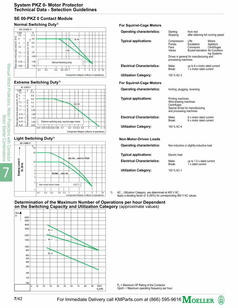
7
Manual M
otor Protectors, M
otor Protectors w
ith Contactor
Motor S
tarter Com
binations
7/42
System PKZ 0- Motor ProtectorTechnical Data - Selection Guidelines
SE 00-PKZ 0 Contact Module
Normal Switching Duty1)For Squirrel-Cage Motors
Operating characteristics:
Typical applications:
Electrical Characteristics:
Utilization Category:
Starting: from restStopping: after attaining full running speed
Compressors Lifts MixersPumps Escalators AgitatorsFans Conveyors CentrifugesValves Bucket-elevators Air-Condition-
ing SystemsDrives in general for manufacturing andprocessing machines
Make: up to 6 x motor rated currentBreak: 1 x motor rated current
100 % AC-3
Extreme Switching Duty1)For Squirrel-Cage Motors
Operating characteristics:
Typical applications:
Electrical Characteristics:
Utilization Category:
Inching, plugging, reversing
Printing machinesWire-drawing machinesCentrifugesSpecial drives for manufacturingand processing machines
Make: 6 x motor rated currentBreak: 6 x motor rated current
100 % AC-4
Light Switching Duty1)Non-Motor-Driven Loads
Operating characteristics:
Typical applications:
Electrical Characteristics:
Utilization Category:
Non-inductive or slightly-inductive load
Electric heat
Make: up to 1.5 x rated currentBreak: 1 x rated current
100 % AC-1
Determination of the Maximum Number of Operations per hour Dependenton the Switching Capacity and Utilization Category (approximate values)
1) AC... Utilization Category are determined at 400 V AC.Apply a derating factor of .9 (90%) for corresponding 460 V AC values.
PN = Maximum HP Rating of the Contactor.Ops/h. = Maximum operating frequency per hour.
For Immediate Delivery call KMParts.com at (866) 595-9616

7
Man
ual M
otor
Pro
tect
ors,
Mot
or P
rote
ctor
s w
ith C
onta
ctor
Mot
or S
tart
er C
ombi
natio
ns
7/43
Tripping Characteristics Manual Motor Protectors,Motor Protector Combinations
Let-Through Current Characteristics,Manual Motor Protectors
Let-Through Energy Characteristics,Manual Motor Protectors
Let-Through Current Characteristics,Motor Protector Combinations
Let-Through Energy Characteristics,Motor Protector Combinations
System PKZ 0- Motor ProtectorTechnical Data - Tripping Characteristic, Let-Through Curves
For Immediate Delivery call KMParts.com at (866) 595-9616

7
Manual M
otor Protectors, M
otor Protectors w
ith Contactor
Motor S
tarter Com
binations
Standards
Climatic Proofing
Ambient Temperature
Mounting Position
Direction of Incoming Supply
Environmental rating (Field-wiring terminals)Protection against electric shock hazardsImpact Shock Resistance (Half-sinusoidal shock 10 ms)
AltitudeIEC Terminal Capacities1 Conductor: Solid
Flexible with Ferrule2 Conductors: Solid
Flexible with FerruleUL/CSA Terminal Capacities
Tightening torque
IEC/EN 60 947 Data:Rated Impulse Withstand Voltage Uimp
Overvoltage Category / Pollution DegreeMaximum Rated Operational Voltage Ue
Rated Uninterrupted Current Iu = Rated Operational Current IeRated FrequencyNumber of PolesCurrent Heat Losses
Lifespan, Mechanical
Lifespan, Electrical
Max. Operating Frequency
Temperature Compensation– IEC/EN 60 947, VDE 0660– Operating RangeTemperature Compensation Residual Error
Thermal Trip Dial Setting RangeFixed Magnetic Trip ResponseMagnetic Trip ToleranceSingle-Phasing Sensitivity
7/44
General
StorageOpenEnclosed
Power terminalsControl Terminals
3-Pole, warm state
min./max. ºCmin./max. ºCmin./max. ºC
g
m
min./max. mm2
min./max. mm2
min./max. mm2
min./max. mm2
min./max. AWG
NmNm
V
V ACAHz
W
Ops.
Ops.
Ops./hr
min./max. ºCmin./max. ºC
%/K
x Iu
x Iu
%
1 Phase HP @
PKZM 0-1.6
PKZM 0-2.5
PKZM 0-4.0
PKZM 0-6.3
PKZM 0-10
PKZM 0-16
PKZM 0-20...25
S(E) 00-...
IEC/EN 60 947, VDE 0660, UL 508, CSA C 22.2 No. 14, CE,GL, LR, DNV, PRS, BV, RINA, RS, MEEI, EZU
Damp Heat, Constant, to IEC 60 068 Part 2-3Damp Heat, Cyclical, to IEC 60 068 Part 2-30-25/+70-25/+55-25/+40
Manual Motor Protector: OptionalMotor Protector Combination: From the topIP 20 (IP 00)Finger- and back-of-hand proof to IEC 536 (VDE 0106 Part 100)Manual Motor Protector: 25Motor Protector Combination: 82000
1 - 61 - 41 - 2.51 - 2.514 - 10
1.81.0
6000III/369025 or Thermal Trip Dial Setting40 - 603Manual Motor Protector: 6Combination Motor Protector: 9.5Manual Motor Protector: 0.1 x 10⁶
(High Capacity) Magnetic Contactor: 5.0 x 10⁶
Refer to Utilization Curves on page 7/42
Manual Motor Protector: 40(High Capacity) Magnetic Contactor: See Curve on page 7/42
-5/+40-25/+55≤ 0.25 - 0.4
0.6...114 (20 for PKZM 0-...T)± 20IEC/EN 60 947-4-1, DIN VDE 0660 Part 102, UL 508, CSA 22.2 # 14
115 V AC 200 V AC 230 V AC
- - 1/10
- 1/81/6
1/81/4
1/31/4
1/21/2
1/2 1 11/21 2 211/2 3 3
1/2 1 11/2
Main Contacts
Trip Blocks
UL/CSA Single Phase HP Ratings
Manual Motor Protector Type
(High Capacity) Magnetic Contactor
Always use 3 Poles for wiring
System PKZ 0- Motor ProtectorTechnical Data
90° 90°
PKZM 0
PKZM 0/S(E) 00
For Immediate Delivery call KMParts.com at (866) 595-9616

7
Man
ual M
otor
Pro
tect
ors,
Mot
or P
rote
ctor
s w
ith C
onta
ctor
Mot
or S
tart
er C
ombi
natio
ns
7/45
AC Operation
Operating Range ( Us = Coil Voltage Rating)Single-Voltage Coil 50 Hz andDual-Voltage Coil 50 Hz, 60 Hz
Dual-Frequency Coil...V 50/60 Hz
Power ConsumptionSingle-Voltage Coil 50 Hz andDual-Voltage Coil 50 Hz, 60 Hz
Dual Frequency Coil...V 50/60 Hz at 50 Hz
...V 50/60 Hz at 60 Hz
Operating Times at 100 % Us
DC Operation
Operating RangePower ConsumptionOperating Times at 100 % Us
Duty Factor
Component Lifespan
Terminal Capacities1 Conductor or 2 ConductorsSolid or Flexible with Ferrule
S(E) 00-PKZ 0 Magnetic Contactors
Pick-upDrop-out
Pick-upDrop-out
Pick-upSealing
Pick-upSealing
Pick-upSealing
(Main Contacts)Closing DelayOpening Delay
Pick-upPick-up = Sealing(Main Contacts)Closing DelayOpening Delay
min./max.min./max.
AC 3 kW Rating @
PKZM 0-0.16
PKZM 0-0.25
PKZM 0-0.4
PKZM 0-0.63
PKZM 0-1
PKZM 0-1.6
PKZM 0-2.5
PKZM 0-4.0
PKZM 0-6.3
PKZM 0-10
PKZM 0-16
PKZM 0-20
PKZM 0-25
PKZM 0-0.16/S(E) 00...
PKZM 0-0.25/S(E) 00...
PKZM 0-0.4/S(E) 00...
PKZM 0-0.63/S(E) 00...
PKZM 0-1/S(E) 00...
PKZM 0-1.6/S(E) 00...
PKZM 0-2.5/S(E) 00...
PKZM 0-4.0/S(E) 00...
PKZM 0-6.3/S(E) 00...
PKZM 0-10/S(E) 00...
x Us
x Us
x Us
x Us
VA/WVA/W
VA/WVA/W
VA/WVA/W
msms
x Us
W
msms% DF
mm2
AWG
0.85 - 1.10.4 - 0.6
0.85 - 1.10.25 - 0.5
25/224.6/1.3
30/265.6/1.6
29/243.9/1.1
14 - 218 - 18
0.85 - 1.12.6
26 - 3515 - 20100
Lifespan Characteristics Page 7/42
1 - 2.518 - 14
220 V 380 V 440 V 500 V 660 V230 V 400 V 690 V240 V 415 V
kW kW kW kW kW- - - - 0.06- 0.06 0.06 0.06 0.120.06 0.09 0.12 0.12 0.180.09 0.12 0.18 0.25 0.250.12 0.25 0.25 0.37 0.550.25 0.55 0.55 0.75 1.10.37 0.75 1.1 1.1 1.50.75 1.5 1.5 2.2 31.1 2.2 3 3 42.2 4 4 4 7.54 7.5 9 9 12.55.5 9 11 12.5 155.5 12.5 12.5 15 22
- - - - 0.06- 0.06 0.06 0.06 0.120.06 0.09 0.12 0.12 0.180.09 0.12 0.18 0.25 0.250.12 0.25 0.25 0.37 0.550.25 0.55 0.55 0.75 1.10.37 0.75 1.1 1.1 1.50.75 1.5 1.5 2.2 31.1 2.2 3 3 42.2 4 4 4 -
Magnet System
System PKZ 0- Motor ProtectorTechnical Data
System PKZ 0 Motor ProtectorIEC kW Ratings (AC 3)
Manual Motor Protector Type
Motor Protector + ContactorCombination
For Immediate Delivery call KMParts.com at (866) 595-9616

7
Manual M
otor Protectors, M
otor Protectors w
ith Contactor
Motor S
tarter Com
binations
UL/CSA Pilot Duty Ratings
IEC/EN 60 947 RatingsRated Operational Current IeAC-15
DC-13 (L/R ≤ 100 ms)
Component Lifespan
Control Circuit ReliabilityFault Probability at Rated Operational Voltage 24 V DC(Umin = 17 V, Imin = 5.4 mA)
Positively Driven Contacts to ZH 1/457
Terminal Capacities1 or 2 ConductorsSolid or Flexible (with Ferrule for IEC/EN applications)
IEC/ENUL/CSA
Rated Operational Voltage Ue
Terminal Capacities1 or 2 ConductorsSolid or Flexible (with Ferrule for IEC/EN applications)
IEC/ENUL/CSA
Operating Range ACDC (Intermittent Operation: 5 s)
Power Consumption
Pick-up VoltageDrop-out Voltage
Power Consumption
7/46
Auxiliary Contacts
A 600, Q 300 E 150 (for NHI-E-...-PKZ 0)NHI...(S),AGM...
3.5 1 (for NHI-E-...-PKZ 0)212 2 (for NHI-E-...-PKZ 0)1.5 1 (for NHI-E-...-PKZ 0)1 0.5 (for NHI-E-...-PKZ 0)0.25 0.25 (for NHI-E-...-PKZ 0)NHI 0.1 x 10⁶
NHI-E-... 0.1 x 10⁶
AGM 0.01 x 10⁶
NHI...S, HI 5 x 10⁶
NHI 0.05 x 10⁶
NHI-E-... 0.1 x 10⁶
AGM 5 x 10³
NHI...S, HI 1 x 10⁶
< 10-8, < 1 Fault in 1 x 10⁸ Operations
NHI 11, NHI 12, NHI 21
NHI 2-11S, HI 11-S/EZ
0.75 - 2.5 0.75 - 1.5 (for NHI-E-...-PKZ 0)18 - 14 18 - 16 (for NHI-E-...-PKZ 0)
42 - 48024 - 250
0.75 - 2.518 - 14
0.7 - 1.10.7 - 1.1
5333
0.850.7 - 0.35
53
Voltage Trips- General
Shunt Trips
Undervoltage Trips
220 - 240 V380 - 415 V440 - 500 V24 V60 V110 V220 VMechanical
Electrical
min./max.min./max.
min./max.min./max.
Pull-in ACSealing ACPick-up DCSealing DC
Pull-in ACSealing AC
AAAAAAAOps.
Ops.
mm2
AWG
V ACV DC
mm2
AWG
x Us
x Us
VAVAWW
x Us
x Us
VAVA
PKZM 0 Motor Protector Trip curveThe trip curve shows the tripping time of the MotorProtector in relation to the response current. The curveshows mean values of the tolerance ranges at an ambienttemperature of 20 ºC, starting from cold. The trippingtime of the bimetal trips at operational temperature (warmstate) is reduced to approximately 1/4 of the values shown.System PKZ 0 Motor Protectors are suitable for protectionof IEC Type EEx e- explosion-proof motors.Specific characteristics for each individual setting rangeare available on request. These characteristics, in 55 x75 mm format (self-adhesive), can be used as on-sitedocumentation to verify the suitability of each MotorProtector for this application. The data has beenindependently verified by the German PTB testing agencyand laboratory.
(Us = Trip coil rated voltage)
(Us = Trip coil rated voltage)
System PKZ 0 Motor Protectors:Suitable for protection of IEC Type EEx eExplosion-proof motors.
System PKZ 0- Motor ProtectorTechnical Data
2
5
20
50
200
1
2
5
102040
12
5
1020
2h
1.5 2 3 4 6 8 10 15 20 30
PKZM 0-...
PKZM 0-.../SE 00...
PKZM 0-.../S 00
Sec
onds
Min
utes
Mill
isec
onds
Trip
ping
tim
e
x Rated operational current
3 phase
2 phase
For Immediate Delivery call KMParts.com at (866) 595-9616

7
Man
ual M
otor
Pro
tect
ors,
Mot
or P
rote
ctor
s w
ith C
onta
ctor
Mot
or S
tart
er C
ombi
natio
ns
7/47
System PKZ 0 Short Circuit Ratings per IEC/EN 60 947 Standards for international applications
Iu
A
0.16 - 11.62.546.310162025
0.16 - 11.62.546.310162025
0.16 - 11.62.546.310162025
0.16 - 11.62.546.310
Iq
kA
161616
Icu
kA
161616
------
Ics
kA
888
------
A1)
NNNNNN505050
NNNNNNNNN
NNNNNNNNN
NNNNNN
Iq
kA
161616
Icu
kA
161616
------
Ics
kA
888
------
A1)
NNNNNN505050
NNNNNNNNN
NNNNNNNNN
NNNNNN
Iq
kA
10101010
Icu
kA
10101010
------
Ics
kA
10101010
------
A1)
NNNNN50505050
NNNNNNNNN
NNNNNNNNN
NNNNNN
Iq
kA
66666
5020201010
4040402020
66
Icu
kA
66666
5020201010
4040402020
------
Ics
kA
66666
5020201010
4040402020
------
A1)
NNNN5050505050
NNNNNNNNN
NNNNNNNNN
NNNN5050
Icu
kA
5333333
20202020555
40402020101010
------
Ics
kA
5322222
2020202020202.52.52.5
AAAAAAAAA
------
A1)
NN50505050505050
NNNNNNNNN
NNNNNNNNN
NN50505050
230 V 400 V 440 V 500 V 690 V
Motor Protector Combination PKZM 0-.../SE 00.... (Coordination) Type "1" and PKZM 0-.../S 00... Type “1” and "2"
PKZM 0+CL-PKZ 0+ upstream CL-PKZ 0 used as additional back-up protection
PKZM 0-... Motor Protector +CL-PKZ 0 Current Limiter
PKZM 0-... Motor Protector, Coordination Types "1" and "2"
Iu = Maximum Continuous Current Rating of each device. Iq = Conditional Short Circuit Current Rating (per IEC/EN 60 947-4-1, relevant for Motor Starters and Motor Starter Combinations) Icu = Ultimate Breaking Capacity (per IEC/EN 60 947-2, relevant for circuit breakers) Ics = Continuity of Service Breaking Capacity (per IEC/EN 60 947-2, relevant for circuit breakers)(All kA ratings are RMS Sym. values)
– Indicates Self-Protected Range (100 kA)N – Not necessary. Back-up protection is not required since device is operating within its self-protected range.A – On Request
System PKZ 0- Motor ProtectorTechnical Data
1) Additional Back-up protection is required whenever the available short circuit fault current exceeds the Iq Conditional Short Circuit Current Rating of the device shown in the table.The Conditional Short Circuit Current Rating is then dependent on the short circuit rating of the fuse:
With 50 A gL Characteristic fuse Iq = 100kAWith 100 A gL Characteristic fuse Iq = 30 kA
Iq
kA
5333333
20202020555
40402020101010
5533
For Immediate Delivery call KMParts.com at (866) 595-9616

7
Manual M
otor Protectors, M
otor Protectors w
ith Contactor
Motor S
tarter Com
binations
7/48
S-PKZ 2 Contact Module
Normal Switching Duty1) For Squirrel-Cage Motors
Operating characteristics:
Typical applications:
Electrical Characteristics:
Utilization Category:
Starting: from restStopping: after attaining full running speed
Compressors Lifts MixersPumps Escalators AgitatorsFans Conveyors CentrifugesValves Bucket-elevators Air-Condition-
ing SystemsDrives in general for manufacturing andprocessing machines
Make: up to 6 x motor rated currentBreak: 1 x motor rated current
100 % AC-3
Extreme Switching Duty1) For Squirrel-Cage Motors
Operating characteristics:
Typical applications:
Electrical Characteristics:
Utilization Category:
Inching, plugging, reversing
Printing machinesWire-drawing machinesCentrifugesSpecial drives for manufacturingand processing machines
Make: 6 x motor rated currentBreak: 6 x motor rated current
100 % AC-4
Light Switching Duty1) Non-Motor-Driven Loads
Operating characteristics:
Typical applications:
Electrical Characteristics:
Utilization Category:
Non-inductive or slightly-inductive load
Electric heat
Make: up to 1.5 x rated currentBreak: 1 x rated current
100 % AC-1
Determination of the Maximum Number of Operations per hour Dependenton the Switching Capacity and Utilization Category (approximate values)
0.1 0.2 0.4 0.6 0.8 1 2 3 4 5 6 8 10
0.811.051.42
1.86
2.65
5.2
6.8
8.811.415.4
22.128.5
35
3.6
0.250.37
0.55
0.75
1.1
2.2
3
45.57.5
1115
18.5
1.5
AC-3/400V
kW AS(E1A)-PKZ2
Rat
ed o
utpu
t of t
hree
-pha
sem
otor
s 50
...60
Hz
Component lifespan (millions of operations)
Rat
ed o
pera
tiona
lcu
rren
t 50.
..60
Hz
Normal switching duty
0.811.051.42
1.86
2.65
5.2
6.8
8.811.415.4
22.128.5
35
3.6
0.250.370.55
0.75
1.1
2.2
3
45.57.5
1115
18.5
1.5
AC-4/400V
kW A
0.01 0.02 0.03 0.04 0.06 0.1 0.2 0.3 0.4 0.6 1 2 3 4
S(E1A)-PKZ2
5
Rat
ed o
pera
tiona
lcu
rren
t 50
...60
Hz
Rat
ed o
utpu
t of t
hree
-pha
sem
otor
s 50
...60
Hz
Component lifespan (millions of operations)
Extreme switching duty, squirrel-cage motors
0.1 0.2 0.4 0.6 0.8 1 2 3 4 5 6 8 10
0.811.051.42
1.86
2.65
5.2
6.8
8.811.415.422.128.5
35
3.6
AC-1/400V
A40
Bre
akin
g cu
rren
t
Component lifespan (millions of operations)
Non-motor loads, 3-pole
100
150
200
300
400500600
800
1000
1500
2000
3000
4000
50006000
70009000
100 20 30 40 50 60 70 80 90 100%
Ops./h
AC-3
AC-4
P (kW)N
System PKZ 2- Motor ProtectorTechnical Data - Selection Guidelines
1) AC... Utilization Category are determined at 400 V AC.Apply a derating factor of .9 (90%) for corresponding 460 V AC. values.
PN = Maximum HP Rating of the Contactor.Ops/h. = Maximum operating frequency per hour.
For Immediate Delivery call KMParts.com at (866) 595-9616
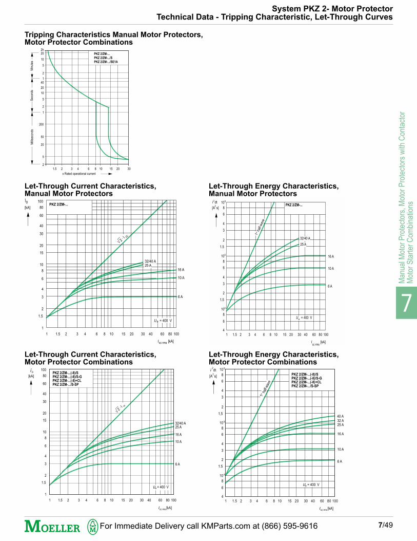
7
Man
ual M
otor
Pro
tect
ors,
Mot
or P
rote
ctor
s w
ith C
onta
ctor
Mot
or S
tart
er C
ombi
natio
ns
7/49
2
5
20
50
200
1
2
5
10
20
401
2
5
20
10
2h
1.5 2 3 4 6 8 10 15 20 30
PKZ 2/ZM-...
PKZ 2/ZM-.../S
PKZ 2/ZM-.../SE1A
Sec
onds
Mill
isec
onds
Min
utes
x Rated operational current
1
1
1.5
2
3
4
6
8
10
15
20
30
40
60
80
100
1.5 2 3 4 6 8 10 15 20 30 40 60 80 100
PKZ 2/ZM-...
2 · I cc
32/40 A25 A
16 A
10 A
6 A
ÎD
[kA]
I [kA]cc rms
U = 400 Ve
1 1.5 2 3 4 6 8 10 15 20 30 40 60 80 1004
6
8
1.5
2
3
4
6
8
1.5
2
3
4
6
8
105
104
106
PKZ 2/ZM-...
16 A
10 A
6 A
32/40 A
25 A
i dt2
[A s]2
U = 400 Ve
I [kA]cc rms
1stha
lf-w
ave
1
1
1.5
2
3
4
6
8
10
15
20
30
40
60
80
100
1.5 2 3 4 6 8 10 15 20 30 40 60 80 100
PKZ 2/ZM-...(-8)/S
PKZ 2/ZM-...(-8)/S-G
PKZ 2/ZM-...(-8)+CL
PKZ 2/ZM-.../S-SP
2 · I cc
32/40 A25 A
16 A
10 A
6 A
= 400 V
[kA]
e
cc rms
[kA] D
1 1.5 2 3 4 6 8 10 15 20 30 40 60 80 1004
6
8
1.5
2
3
4
6
8
1,5
2
3
4
6
8
10 5
10 4
10 6
16 A
10 A
PKZ 2/ZM-...(-8)/S
PKZ 2/ZM-...(-8)/S-G
PKZ 2/ZM-...(-8)+CL
PKZ 2/ZM-.../S-SP
6 A
25 A32 A40 A
[A s]2
= 400 V
1stha
lf-w
ave
[kA]
e
cc rms
dt2
System PKZ 2- Motor ProtectorTechnical Data - Tripping Characteristic, Let-Through Curves
Tripping Characteristics Manual Motor Protectors,Motor Protector Combinations
Let-Through Current Characteristics,Manual Motor Protectors
Let-Through Energy Characteristics,Manual Motor Protectors
Let-Through Current Characteristics,Motor Protector Combinations
Let-Through Energy Characteristics,Motor Protector Combinations
For Immediate Delivery call KMParts.com at (866) 595-9616

7
Manual M
otor Protectors, M
otor Protectors w
ith Contactor
Motor S
tarter Com
binations
Standards
Climatic Proofing
Ambient Temperature
Mounting Position
Direction of Incoming SupplyEnvironmental ratingMechanical Shock Resistance (Half-sinusoidal shock 20 ms)AltitudeIEC Terminal Capacities1 Conductor: Solid
Flexible with Ferrule2 Conductors: Solid
Flexible with FerruleUL/CSA Terminal Capacities
Tightening Torque
IEC/EN 60 947 Data:Rated Impulse Withstand Voltage Uimp
Overvoltage Category / Pollution DegreeMaximum Rated Operational Voltage Ue
Rated Uninterrupted Current Iu = Rated Operational Current IeRated FrequencyCurrent Heat Losses
Lifespan, Mechanical
Lifespan, Electrical (At max. loading.)(Refer to curves p. 7/48)Max. Operating Frequency
Motor Switching Capacity AC-3Motor Switching Capacity DC-5
DC ApplicationRated Short-Circuit Breaking Capacity
Icn (250 V DC) L/R = 15 msIcn (125 V DC)
Operating Times under Short-Circuit ConditionsMinimum Command TimeOpening DelayTotal Clearing Time
Temperature CompensationTemperature Compensation Residual ErrorMagnetic Trip ToleranceAdjustable Thermal Setting RangeAdjustable Magnetic trip Setting rangeSingle-Phasing Sensitivity
7/50
General
StorageOpenEnclosed
Power terminalsControl Terminals
3-Pole at OperationalTemperature
(100 %) AC-3AC-4
min./max. ºCmin./max. ºCmin./max. ºC
gm
min./max. mm2
min./max. mm2
min./max. mm2
min./max. mm2
min./max. AWG
NmNm
V
V ACAHzW
Ops.
Ops.Ops.Ops./hr
V ACV DCA DC
kAkA
Approx. msApprox. msApprox. ms
min./max. ºC%/K%x Iu
x Iu
IEC/EN 60 947, DIN VDE 0660, UL 508, CSA C 22.2 No. 14, CE,GL, LR, DNV, PRS, BV, RINA, RS, MEEI, EZU
Damp Heat, Constant, to IEC 60 068 Part 2-3Damp Heat, Cyclical, to IEC 60 068 Part 2-30
-25/+70-25/+60-25/+40
Optional, top or bottom feedIP 20Manual Motor Protector: 30 Motor Protector Combination: 82000
1...161.5...101...61.5...614...6
1.81.0
6000III/369042 or Thermal Trip Dial Setting50 - 60Manual Motor Protector: 14 Motor Protector Combination: 23
Manual Motor Protector: 0.1 x 10⁶ High Capacity Magnetic Contactor: 5.0 x 10⁶
(the mechanical life is reduced by 30% for a dual-frequency coil 50/60 Hz)Manual Motor Protector: 0.05 x 10⁶ High Capacity Magnetic Contactor: 1 x 10⁶
High Capacity Magnetic Contactor: 0.03 x 10⁶
Manual Motor Protector: 60High Capacity Magnetic Contactor: Characteristic Curves, Page 7/47
max. 690max. 250max. 40
PKZ 2/ZM-...: PKZ 2/ZM-.../S(+CL):
30 5050 65PKZ 2/ZM-... PKZ 2/ZM-.../S(+CL)
2 20.5 0.56 4
-5/+400.25± 200.6...1.08.5...14IEC/EN 60 947-4-1, DIN VDE 0660 Part 102, UL 508, CSA C 22.2 No. 14
Main Contacts
Motor Protective Trip ModulesZM-...-PKZ 2, ZMR-...-PKZ 2
System PKZ 2- Motor ProtectorTechnical Data
For Immediate Delivery call KMParts.com at (866) 595-9616

7
Man
ual M
otor
Pro
tect
ors,
Mot
or P
rote
ctor
s w
ith C
onta
ctor
Mot
or S
tart
er C
ombi
natio
ns
7/51
AC Operation
Operating Range
Power Consumption
DC OperationRated Coil Voltage Rating Us
Power Consumption
Switching TimesClosing TimeOpening TimeDuty Factor
UL/CSA Pilot Duty Ratings
IEC/EN 60 947 RatingsRated Operational Current Ie
AC-15
NHI 11, NHI 11S, NHI 2-11S, HI 11S/EZ
NHI 22, NHI 22S, HI 11-S, HI 20-S
AGM 2-11
ZMR-... 95 - 9697 - 98
DC-13
ZMR-... L/R ≤ 200 ms
Lifespan, Mechanical
Electrical
Control Circuit ReliabilityFault Probability Hf at Rated Operational Voltage 24 V DC(Umin = 24 V, Imin = 10 mA)
Positively Driven Contacts to ZH 1/457Short-Circuit Rating Without Welding: (IEC/EN 60 204 applications)Fuseless
Fuse
Terminal Capacities1 or 2 ConductorsSolid or Flexible (with Ferrule for IEC/EN applications)
S-PKZ 2 High Capacity Magnetic Contactor
Pull-inDrop-outPull-inSealing
Pull-inPull-inSealingSealing
NHI, NHI...S
AGM
NHI 2-11S, HI...-S
HI 11-S/EZ
ZMR
NHI, NHI...S
AGM
NHI 2-11S, HI...-S
HI 11-S/EZ
ZMR
NHI, NHI...S
AGM
NHI 2-11S, HI...-S
HI 11-S/EZ
ZMR
IEC/EN min./max.
UL/CSA min./max.
Torque
x Us
x Us
VAVA
V DCVAAWmA
msms% DF
AAAAA
A
S
S
A gL
mm2
AWG
Nm
0.85...1.10.4...0.6≤ 190≤ 13
241506.3 (16 - 22 ms)2.7113
9 - 304 - 12100
A 600, R 300A 600, R 300A 600, R 300A 600, R 3000.5 A @ 300 V AC
230/240 V 400/415 V 440/500 V
6 3 1.56 1.5 1.55 3 1.51.5 0.7 0.51.5 0.5 0.3
24 V 60 V 110 V 220 V
1 0.8 0.7 0.3
0.1 x 10⁶
0.01 x 10⁶
5 x 10⁶
5 x 10⁶
0.01 x 10⁶
0.05 x 10⁶
5 x 10³
1 x 10⁶
1 x 10⁶
5 x 10⁶
Fail-Safe over the Entire Mechanical Lifespan
NHI 2-11S, AGM 2-11
With PKZM 0-6.3: 240 VPKZM 0-4: 415 VPKZM 0-1.6: 500 V
10
0.75...2.5
18...14
1
Auxiliary Contacts
Magnet Systems
( Us = Coil Voltage Rating)
Note:24 V DC energization using PLC semi-conductoroutputs is possible. Use PLC Type:PS 416-OUT-410 (Refer to Section 1) and switchingtwo outputs in parallel. The alternative is to use theinterface relay Type ETS 4-VS 3 (Section 2).
System PKZ 2- Motor ProtectorTechnical Data
For Immediate Delivery call KMParts.com at (866) 595-9616

7
Manual M
otor Protectors, M
otor Protectors w
ith Contactor
Motor S
tarter Com
binations
Rated Operational Voltage Ue
Terminal Capacities1 or 2 ConductorsSolid or Flexible (with Ferrule for IEC/EN applications)
IEC/ENUL/CSA
Operating Range
Power Consumption AC
DC
Drop-out VoltagePower Consumption AC
DC
Drop-out Delay with UVHI-PKZ 2
Auxiliary Contacts U-HI 20-PKZ 2, UVHI-PKZ 2:
IEC/EN 60 947 Rated Operational Current Ie AC-15
UL/CSA Pilot Duty Ratings
Rated Operational Voltage Ue AC (50/60 Hz), DCUe AC (50/60 Hz)
Necessary short-time power requirementControl Transformer Short-Time duration Power RatingTotal Closing TimeTotal Opening TimeReset to OFF TimeOperating FequencyOperating Range AC
DCLifespan, Electrical
Integral Auxiliary Contacts (Hand/Auto 33/34):UL/CSA Pilot Duty RatingsIEC/EN 60 947 Rated Operational Current Ie
AC-14
Terminal Capacities1 or 2 ConductorsSolid or Flexible (with Ferrule for IEC/EN applications)
IEC/ENUL/CSA
UL/CSA Data:Maximium Rated VoltageMaximum Rated Current Type B 3.1/2-PKZ 2
Type B 3.1/3-PKZ 2
UL/CSA Data:Maximium Rated VoltageMaximum Rated Current Type BK 50/3-PKZ 2
Terminal Capacities UL/CSA
7/52
Voltage Trips- General
24...600A-PKZ 2: 24...250; U-PKZ 2: 24...125
0.75...2.522...14
0.7...1.10.7...1.15330.3
0.7...0.355333200
230 V 400 V 440 V6 3 1.5
B600, R300
24...120 (> 120V, IEC only)380...440 (IEC only)
700 VA/W, for a duration of 30 ms1100 VA –> (Use STI 0.4 transformer from Section 12)≤ 30≤ 30≤ 30600.85...1.10.85...150000
D 300, R 300
230/240 V 400/415 V 440 V
1.5 1 0.5
0.75...2.522...14
60085100
600100A
14...04.5
RE-PKZ 2, RS-PKZ 2 Remote Control Drives
Shunt Trips
Undervoltage Trips
min./max.min./max.
ACDCPull-inSealingPull-inSealing
Pull-inSealingPull-inSealing
min./max.min./max.
min./max.Torque Rating
V ACV DC
mm2
AWG
x Us
x Us
VAVAWW
x Us
VAVAWWms
A
VV
VA/WVAmsmsmsOps./hx Us
x Us
Operations
50 Hz
A
mm2
AWG
V ACAA
V ACA
AWGNm
Bus connector Incoming SupplyTerminal
Three Phase Feeder Bus Connectors
System PKZ 2- Motor ProtectorTechnical Data
(Us = Trip coil rated voltage)
(Us = Trip coil rated voltage)
(Us = Trip coil rated voltage)
For Immediate Delivery call KMParts.com at (866) 595-9616

7
Man
ual M
otor
Pro
tect
ors,
Mot
or P
rote
ctor
s w
ith C
onta
ctor
Mot
or S
tart
er C
ombi
natio
ns
7/53
Circuit Diagram
For PKZ 2/ZMR-...
and PKZ 2/ZMR-.../S
Note: Use of the ZMR-...-PKZ 2
Protective Trip Module in EEx eapplications:In EEx e applications the N.C. 95 - 96of the ZMR protective trip modulemust always be wired in series withthe contactor coil in the starter circuit.See diagram above.
I >
M
3~
I
O
13
14K1
95
96
K1
97
98
K1
ZMR-
Position
"Overload"
System PKZ 2- Motor ProtectorTechnical Data
PKZ2/ZM(R)-...(/S) Motor Protector Trip curve
The trip curve shows the tripping time of the MotorProtector in relation to the response current. The curveshows mean values of the tolerance ranges at an ambienttemperature of 20 ºC, starting from cold. The trippingtime of the bimetal trips at operational temperature (warmstate) is reduced to approximately 1/4 of the values shown.System PKZ 2 Motor Protectors are suitable for protectionof IEC Type EEx e- explosion-proof motors.Specific characteristics for each individual setting rangeare available on request. These characteristics, in 55 x75 mm format (self-adhesive), can be used as on-sitedocumentation to verify the suitability of each MotorProtector for this application. The data has beenindependently verified by the German PTB testing agencyand laboratory.
System PKZ 2 Motor Protectors:Suitable for protection of IEC Type EEx eExplosion-proof motors.
1 Phase HP @
PKZ 2/ZM-1.6
PKZ 2/ZM-2.4
PKZ 2/ZM-4
PKZ 2/ZM-6
PKZ 2/ZM-10
PKZ 2/ZM-16
PKZ 2/ZM-25
PKZ 2/ZM-32
PKZ 2/ZM-40
S-PKZ 2
AC 3 kW Ratings @
PKZ 2/ZM-0.6
PKZ 2/ZM-1
PKZ 2/ZM-1.6
PKZ 2/ZM-2.4
PKZ 2/ZM-4
PKZ 2/ZM-6
PKZ 2/ZM-10
PKZ 2/ZM-16
PKZ 2/ZM-25
PKZ 2/ZM-32
PKZ 2/ZM-40
PKZ 2/ZM-0.6/S...
PKZ 2/ZM-1/S...
PKZ 2/ZM-1.6/S...
PKZ 2/ZM-2.4/S...
PKZ 2/ZM-4/S...
PKZ 2/ZM-6/S...
PKZ 2/ZM-10/S...
PKZ 2/ZM-16/S...
PKZ 2/ZM-25/S...
PKZ 2/ZM-32/S...
PKZ 2/ZM-40/S...
UL/CSA Single Phase HP Ratings
Manual Motor Protector Type
(High Capacity) Magnetic Contactor
Manual Motor Protector Type
Motor Protector + ContactorCombination
Always use 3 Poles for wiring 115VAC 200VAC 230VAC
- - 1/10
- 1/81/6
1/81/4
1/31/4
1/21/2
1/2 1 11/21 2 22 3 32 5 53 5 71/2
3 5 71/2
220V 380V 440V 500V 660V230V 400V 690V240V 415V
kW kW kW kW kW0.09 0.12 0.18 0.25 0.250.18 0.25 0.25 0.37 0.550.25 0.55 0.55 0.8 1.10.37 0.8 1.1 1.1 1.50.8 1.5 1.5 2.2 31.5 2.5 3 3 42.5 4 5 5.5 7.54 7.5 9 10 13.55.5 12.5 12.5 15 227.5 15 17.5 22 2211 20 22 24 30
0.09 0.12 0.18 0.25 0.250.18 0.25 0.25 0.37 0.550.25 0.55 0.55 0.8 1.10.37 0.8 1.1 1.1 1.50.8 1.5 1.5 2.2 31.5 2.5 3 3 42.5 4 5 5.5 7.54 7.5 9 10 13.55.5 12.5 12.5 15 227.5 15 17.5 22 2211 20 22 24 30
Three Phase IEC kW Ratings (AC 3)
PKZ 2/ZM(R)-...
PKZ 2/ZM(R)-.../S
1,5 2 3 4 6 10 15 20 3082
5
20
50
200
1
2
5
10
20
401
5
10
20
2
2h
3 phase2 phaseM
inut
esS
econ
dsM
illis
econ
ds
x Rated Current
For Immediate Delivery call KMParts.com at (866) 595-9616

7
Manual M
otor Protectors, M
otor Protectors w
ith Contactor
Motor S
tarter Com
binations
Iq
kA
4.54.54.54.54.54.54.5
10101010101010
101010
Iq
kA
77777
Iq
kA
1010101010
Iq
kA
303030
Iq
kA
303030
Icu
kA
303030
----
Ics
kA
30307.57.57.5
30307.57.57.5
----
A
NNNNNN160160160
NNNNNNNNN
NNNN
Icu
kA
303030
----
Ics
kA
30307.57.57.5
30307.57.57.5
----
A
NNNNNN160160160
NNNNNNNNN
NNNN
Icu
kA
1010101010
----
Ics
kA
55555
55555
----
A
NNNN80100125160160
NNNNNNNNN
NNNN
Icu
kA
77777
----
Ics
kA
3.53.53.53.53.5
3.53.53.53.53.5
----
A
NNNN80100125160160
NNNNNNNNN
NNNN
Icu
kA
4.54.54.54.54.54.54.5
4.54.54.54.54.54.54.5
----
Ics
kA
2.52.52.52.52.52.52.5
2.52.52.52.52.52.52.5
----
A
NN638080100125160160
NNNNNNNNN
N80100160
7/54
Iu
A
0.16 - 1.62.4461016253240
0.16 - 1.62.4461016253240
0.6 - 2.44 - 610 - 1625 - 40
230 V 400 V 440 V 500 V 690 V
PKZ 2/ZM-.../S(-G) High capacity Motor Protector Combination, Coordination Types "1" and "2"
PKZ 2/ZM-... Motor Protector + CL-PKZ 2 Current Limiter, Coordination Types "1" and "2"
PKZ 2/ZM-...Motor Protector, Coordination Types "1" and "2"
System PKZ 2 Short Circuit Ratings per IEC/EN 60 947 Standards for international applications
Iu = Maximum Continuous Current Rating of each device. Iq = Conditional Short Circuit Current Rating (per IEC/EN 60 947-4-1, relevant for Motor Starters and Motor Starter Combinations) Icu = Ultimate Breaking Capacity (per IEC/EN 60 947-2, relevant for circuit breakers) Ics = Continuity of Service Breaking Capacity (per IEC/EN 60 947-2, relevant for circuit breakers)(All kA ratings are RMS Sym. values)
– Indicates Self-Protected Range (100kA)N – Not necessary. Back-up protection is not required whenever device is operating within its self-protected range or up to the available short circuit fault
current value shown in each respective column.
System PKZ 2- Motor ProtectorTechnical Data
For Immediate Delivery call KMParts.com at (866) 595-9616

7
Man
ual M
otor
Pro
tect
ors,
Mot
or P
rote
ctor
s w
ith C
onta
ctor
Mot
or S
tart
er C
ombi
natio
ns
7/55
System PKZ 0Dimensions
Manual Motor Protectors
PKZM 0-... (+NHI-E-...-PKZ 0)PKZM 0-...TPKZ 0-...
NHI-E-...-PKZ 0
NHI-E-...-PKZ 0
70
55
45
93
50
7668
45
PKZM 0-... +AK-PKZ 0
45
AK-PKZ 0
AK-PKZ 0
93
508894
45
Current Limiters
CL-PKZ
70
7.5
49.5
447.5
45
28
90 73 93
EN 50 022Top-hat rail
Manual Motor Protectors
PKZM 0-... +VHI-...-PKZ 0
VHI...-PKZ0
80
55
45
93
50
86
68
45
VHI...-PKZ0
Magnetic Motor Protector Combinations
PKZM 0-.../S(E) 00 (+NHI-E-...-PKZ 0)
U/A AGM
NHI
144
162
195
75
77
NHI-E-..-PKZ 0
NHI-E-...-PKZ 0
Standard Auxiliary Contacts for Motor ProtectorCombinations
NHI 2-11S-PKZ 0
18 26
68
115
161
Standard Auxiliary Contacts
NHI...-PKZ 0
9 26
68
45 9036
Trip-Indicating Auxiliary Contacts
AGM 2-...-PKZ 0
9 26
68
45 9036
Voltage Trips
U/A-PKZ 0
18 49
68
36 45 90
For Immediate Delivery call KMParts.com at (866) 595-9616

7
Manual M
otor Protectors, M
otor Protectors w
ith Contactor
Motor S
tarter Com
binations
Magnetic Contactor Modules
S(E) 00-PKZ 0
45 75
94
7/56
System PKZ 0Dimensions
Separate Mounting
EZ-PKZ 0
45 83
99
Auxiliary Contacts for Magnetic Contactor Modules
HI 11-S/EZ-PKZ 0
9 33
68
42 90
Mechanical Interlocks
MV-PKZ 0
83
99
15
9 9105
Three-Phase Feeder Bus Connectors
B3.0/2-PKZ 0B3.0/4-PKZ 0
180 (90)
H-B3-
PKZ 0
27
45
B3.2/2-PKZ 0B3.2/4-PKZ 0
234 (108)
H-B3-
PKZ 027
63
Three-Phase Feeder Bus Connectors
B3.1/2-PKZ 0B3.1/3-PKZ 0B3.1/4-PKZ 0B3.1/5-PKZ 0
H-B3-
PKZ 027
261 (207, 153, 99)
54
Terminals
BK25/3-PKZ 0
Cover for Unused Terminals
H-B3-PKZ 0
BK 25/3-
PKZ 0
max. 41
69
7.5 31
48
max. 56
B3...-PKZ 0
180
27
45
H-B 3-
PKZ 0
Use overlappingmounting toextend three-phase feederbus connectors.
For Immediate Delivery call KMParts.com at (866) 595-9616

7
Man
ual M
otor
Pro
tect
ors,
Mot
or P
rote
ctor
s w
ith C
onta
ctor
Mot
or S
tart
er C
ombi
natio
ns
7/57
System PKZ 0Dimensions
Insulated Enclosures for Surface Mounting
CI-PKZ 0
80
158
90
100
70
CI-PKZ 0-G(R)(V)
80
158
97.5
125.5
CI-PKZ 0-G(R)(V)+SVB-PKZ 0-CI
98
30
44
55
SVB-PKZ 0-CI
80
158
158
28
33
97.5
30
Drilling dimensions
CI-PKZ 0...
4.5
153
8
R3
4.5
For Immediate Delivery call KMParts.com at (866) 595-9616

7
Manual M
otor Protectors, M
otor Protectors w
ith Contactor
Motor S
tarter Com
binations
7/58
System PKZ 0Dimensions
Insulated Enclosures for Surface Mounting
CI 23 X-125-NA
62
19.5
+l
o
64
64
48
48
43
At least 100 mm
up to cover hinge
Door Coupling Handles
(R)H-PKZ 0, HS0V-PKZ 0
Mounting Plate
M 3-CI 23
69
85
129
96
80
124
55
Insulated Housings for Cavity Mounting
E-PKZ 0E-PKZ 0-G(R)
Mounting Opening
E-PKZ 0...
R4
70–72
116
– 11
8
E-PKZ 0-G(R)+SVB-PKZ 0-E
98
30
58
55
80
96
124
85
129
30
28
21
Mounting depth:100 to 240 mm from top edgeof mounting rail to front edgeof panel door/cover
25
187.5
215
200
162
25
250
225
262
278
7
3
125205
62.5
142.
5
For Immediate Delivery call KMParts.com at (866) 595-9616

7
Man
ual M
otor
Pro
tect
ors,
Mot
or P
rote
ctor
s w
ith C
onta
ctor
Mot
or S
tart
er C
ombi
natio
ns
7/59
System PKZ 0Dimensions
Component Adapters
AD 25/5(10)-1
230
54
56
AD 25/5(10)-2
70
76.5
100
60
108
AD 25/5(10)-144
70
86
230
144
147
For Immediate Delivery call KMParts.com at (866) 595-9616
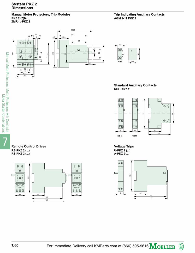
7
Manual M
otor Protectors, M
otor Protectors w
ith Contactor
Motor S
tarter Com
binations
7/60
System PKZ 2Dimensions
Manual Motor Protectors, Trip Modules
PKZ 2/(Z)M-...ZMR-...-PKZ 2
I >
ZMR
6
4.5
0
+
19
9M4
105
1938
62.571.5
20
83 105
68
39.5
109
133.5
62
45
15
ZMR
Trip Indicating Auxiliary Contacts
AGM 2-11 PKZ 2
18
31.5
45
AGM
1818
NHI 22 NHI 11
105
68
44
77
Standard Auxiliary Contacts
NHI...PKZ 2
Remote Control Drives
RE-PKZ 2 (...)RS-PKZ 2 (...)
105
45
109
126
36
RE
A
U
T
O
H
A
N
D
NO
33 34
Control
A20 A40 B20
RS
A
U
T
O
H
A
N
D
NO
33 34
Control 24V only
A20 A30 A0
72 74 72 74
36
Voltage Trips
U-PKZ 2 (...)A-PKZ 2-...
18 44109113
105
For Immediate Delivery call KMParts.com at (866) 595-9616
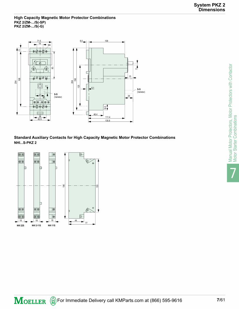
7
Man
ual M
otor
Pro
tect
ors,
Mot
or P
rote
ctor
s w
ith C
onta
ctor
Mot
or S
tart
er C
ombi
natio
ns
7/61
System PKZ 2Dimensions
High Capacity Magnetic Motor Protector Combinations
PKZ 2/ZM-.../S(-SP)PKZ 2/ZM-.../S(-G)
8.5
6
6.1
11
3862.5
168
204
11
27
1971.5
M4
I>
0
+
125
190
204
46.4111.4
135.9
25
15
109
83
18.5
S-G
(Varistor)
S-G
(Varistor)
Standard Auxiliary Contacts for High Capacity Magnetic Motor Protector Combinations
NHI...S-PKZ 2
18 18 18
NHI 22S NHI 2-11S
190
4477
153
NHI 11S
For Immediate Delivery call KMParts.com at (866) 595-9616

7
Manual M
otor Protectors, M
otor Protectors w
ith Contactor
Motor S
tarter Com
binations
7/62
System PKZ 2Dimensions
S(-G) High Capacity Magnetic Contactor Module
CL Current Limiters
77
37
53
125
3819
18 65.5
3
11
100
21.8
EZ Base for Separate Mounting
HI11-S/EZ Standard Auxiliary Contact for EZ Separate Mounting
Enclosures for Surface Mounting
CI 19 EE-PKZ 2-NA CS3-PKZ 2
S1 GK-PKZ 2 CI 43-PKZ 2
85103.
5
44
109
27
19
38
62.5
10
25
Type -G only
23
35.8
41.2
16.7
1817.5 1.2
16.7
34.4 40
16.7
225
262
278
250
25
387
403
25
350
7
3
375
150 150
200
170
127
192
22
240
150
For Immediate Delivery call KMParts.com at (866) 595-9616

7
Man
ual M
otor
Pro
tect
ors,
Mot
or P
rote
ctor
s w
ith C
onta
ctor
Mot
or S
tart
er C
ombi
natio
ns
7/63
System PKZ 2Dimensions
62
19.5
+l
o
64
64
48
48
7.5
43
At least 100 mm
up to cover hinge
Door Coupling Handle
(R)H-PKZ 2
Three-Phase Feeder Bus Connector
B3.1/3 PKZ 2
222
33
B3.1/3 PKZ 2
140
33
60Terminal
BK.50/3-PKZ 2
4.5
4.2
75
18
84.5
78.5
Cover for UnusedTerminals
HB-3-PKZ 2
50
25
Measurementthree-phase feederbus connector
Mechanical Interlock for High CapacityMagnetic Contactor Module
MV-PKZ 2
1.5
14.6
10 10149
21
15
59
56.5
36
128.5
4.5
For Immediate Delivery call KMParts.com at (866) 595-9616

7
Manual M
otor Protectors, M
otor Protectors w
ith Contactor
Motor S
tarter Com
binations
7/64
System PKZ 2Dimensions
230
72
75
Component Adapters
AD 40/5(10)-1 AD 40/5(10)-1
70
86
125
22.5
144
147
For Immediate Delivery call KMParts.com at (866) 595-9616