helping hand 7 dof haptic robotic arm project group 10 …€¦ · · 2013-04-29helping hand –...
TRANSCRIPT

Helping Hand – 7 DOF
Haptic Robotic Arm Project
Group 10 – Spring 2013
Taylor Jones, Kurt Graf, Matt Carlson,
Eric Donley
University of Central Florida,
DEPARTMENT OF ELECTRICAL
ENGINEERING AND COMPUTER
SCIENCE, Orlando, Florida, P.O.Box
160000 Orlando, FL 32816, USA
Abstract -- The purpose of the senior design project,
from the course description of objectives is "To provide students a complete design experience, including the necessity to set design goals and objectives, integrate
knowledge, exercise engineering judgment, plan to meet a budget and schedule, to work as a team member, and to communicate in writing." To accomplish these
objectives our group, Helping Hand, designed a tele-operated master-slave 7 DOF robot arm which motion tracks a human operator's arm motion including open-
close hand tracking by the end-effector. The project is exclusively focused on the electronics and software to control an electrically operated robotic arm. Stock
mechanical robot arms were utilized as needed to accomplish the project. Index Terms — Haptic interfaces, Human robot interaction, Humanoid robots,
Intelligent robots, Intelligent systems, Robotics and automation, Robotic assembly, Robot control, Robot motion, Robot programming, Robot sensing systems, Tele-operators, Tele-robotics.
I. INTRODUCTION
The Helping Hand haptic robotic arm is
investigating robotics as smart (or skilled) as the
human operator, a new phase in human-robotic
interact-ability. Potential applications range from the
pure athletic application of Real Steel (Hollywood
robotic boxing movie) [1] or the Sci-Fi television
channels’ Robot Combat League [2] to augmenting
traditional robotic surgery (Da Vinci systems) [3], or
a simpler programming interface for increasingly
ubiquitous, light-assembly and manufacturing
robotics like RethinkRobotics’ Baxter[4].
Wiki describes haptics as: “Haptic technology, or
haptics, is a tactile feedback technology which takes
advantage of the sense of touch by applying forces,
vibrations, or motions to the user. This mechanical
stimulation can be used to assist in the creation of
virtual objects in a computer simulation, to control
such virtual objects, and to enhance the remote
control of machines and devices (tele-robotics).
Haptic devices may incorporate tactile sensors
that measure forces exerted by the user on the
interface.” [5] “It has been described as "doing for
the sense of touch what computer graphics does for
vision". [6] The new cheap and readily usable MEMS
gyros make motion analysis of a human operator
directly programmable into an embedded robotic
control system very facile and readily
accomplishable.
Essentially, the Helping Hand is an exteroceptive
control system “activated by, relating to, or being
stimuli received by an organism from outside
<exteroceptive feedback>.” [7] More simply, the
human operator provides spontaneous control
feedback of the human-robot interactive system. The
current system is direct mechanical control of the
robot arm by the human operator’s arm motion.
Potential future applications include a sensor glove
for human hand motion duplication - for skilled work
robotic duplication - or direct human - motion
programming e.g. programmer’s sensor jacket,
directly programming a humanoid worker robot in a
one-to-one learning/programming dynamic.
II. PROJECT DESCRIPTION
Our project is a Haptic Robotic Arm controlled by
Velcro strap mounted motion and force sensors on a
human operator's arm – which controls the motion-
tracking robotic arm's proportional motion. "These
robots have a wide range of industrial and medical
applications such as pick and place robots, surgical
robots etc. They can be employed in places where
precision and accuracy are required. Robots can also
be employed where human hand cannot
penetrate."[8]
III. PROJECT CONCEPT
Why study the human-operated robot arm? The
future of robotics in manufacturing and assembly is
increasing flexibility both in mechanical performance
and ubiquitous integration with human workers. The
future of robotics is greater dexterity, easier and
quicker programmability, and safe operation with
human co-workers. Building a tele-operated master-
slave robot arm driven by sensors worn on a human
arm is investigating future possibilities and general
performance considerations of advanced robotics. An
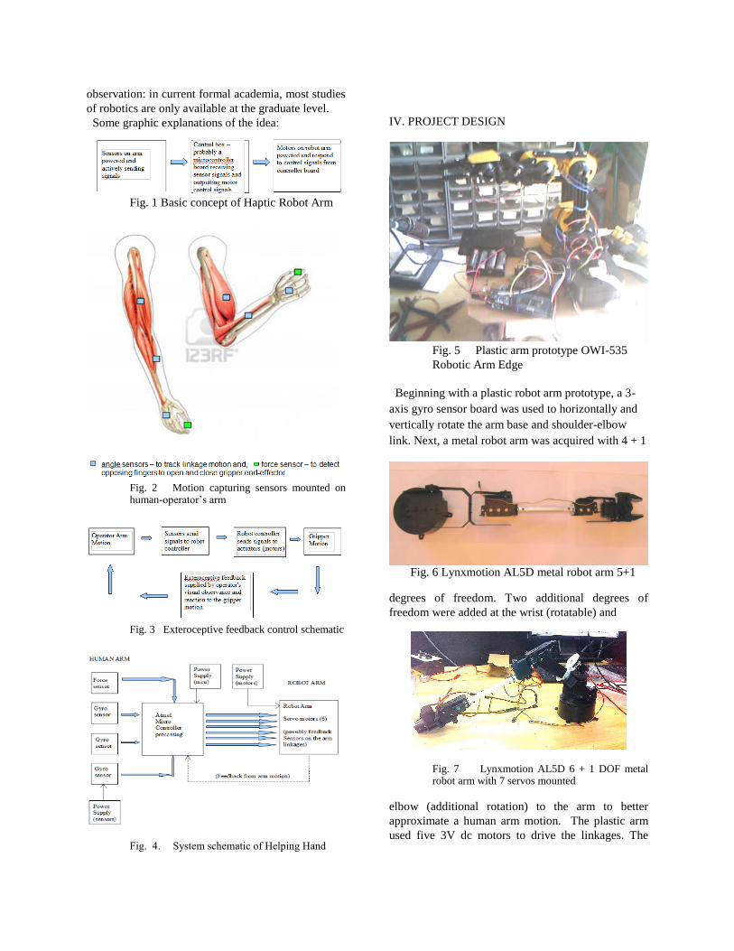
observation: in current formal academia, most studies
of robotics are only available at the graduate level.
Some graphic explanations of the idea:
Fig. 1 Basic concept of Haptic Robot Arm
Fig. 2 Motion capturing sensors mounted on human-operator’s arm
Fig. 3 Exteroceptive feedback control schematic
Fig. 4. System schematic of Helping Hand
IV. PROJECT DESIGN
Fig. 5 Plastic arm prototype OWI-535
Robotic Arm Edge
Beginning with a plastic robot arm prototype, a 3-
axis gyro sensor board was used to horizontally and
vertically rotate the arm base and shoulder-elbow
link. Next, a metal robot arm was acquired with 4 + 1
Fig. 6 Lynxmotion AL5D metal robot arm 5+1
degrees of freedom. Two additional degrees of
freedom were added at the wrist (rotatable) and
Fig. 7 Lynxmotion AL5D 6 + 1 DOF metal robot arm with 7 servos mounted
elbow (additional rotation) to the arm to better
approximate a human arm motion. The plastic arm
used five 3V dc motors to drive the linkages. The

metal arm uses seven 4.8-6.0 volt analog and digital
servo motors to power the final design motion.
V. COMPONENTS
A. MEMS Gyros and Accelerometers
MEMS (micro-electrical mechanical systems)
gyroscopes measure the rate of change around an
axis, which means to determine the amount of
angular change - needed for the robot arm control –
the output of the gyro has to be integrated to find the
amount of angular change.[9] The gyroscopes are
available in basic IC chip format. The physics of
operation of the gyro is a measured Coriolis force
that occurs when a massive object has both
translational and rotational motion simultaneously. If
a rotational motion is applied perpendicularly to the
direction of velocity of an object a Coriolis force is
developed by the right-hand-rule perpendicular to
both the velocity vector and the angular momentum
vector. A capacitive sensing mechanism measures the
force and the measurement is used to determine the
rate of change of angle of motion.
Fig. 8 MEMS 'two masses design' [9]
The MEMS device used is the MPU-6050
Fig. 9 MEMS implementation of above 'two masses design' [10]
Fig. 10 MEMS MPU-6050 4 x 4 x 1 mm (actual size) [11]
The gyro gives data in degrees/second. To
determine actual angle of rotation requires integration
with respect to time:
B. GYRO SENSOR PCB
Three MPU-6050 six-axis gyroscope-accelerometer
combination sensors were implemented on test
boards to measure the human-operator’s arm motion.
Fig. 11 MEMS 6-axis gyro-accelerometer test board
(1)
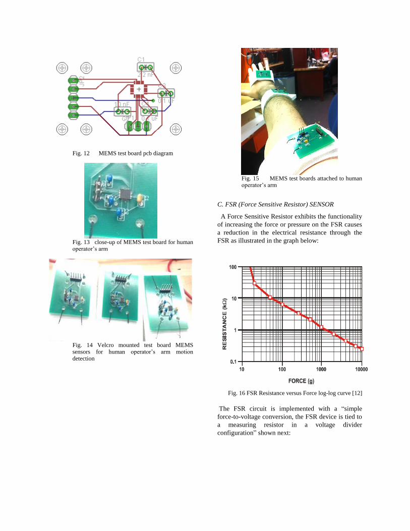
Fig. 12 MEMS test board pcb diagram
Fig. 13 close-up of MEMS test board for human operator’s arm
Fig. 14 Velcro mounted test board MEMS sensors for human operator’s arm motion detection
Fig. 15 MEMS test boards attached to human operator’s arm
C. FSR (Force Sensitive Resistor) SENSOR
A Force Sensitive Resistor exhibits the functionality
of increasing the force or pressure on the FSR causes
a reduction in the electrical resistance through the
FSR as illustrated in the graph below:
Fig. 16 FSR Resistance versus Force log-log curve [12]
The FSR circuit is implemented with a “simple
force-to-voltage conversion, the FSR device is tied to
a measuring resistor in a voltage divider
configuration” shown next:
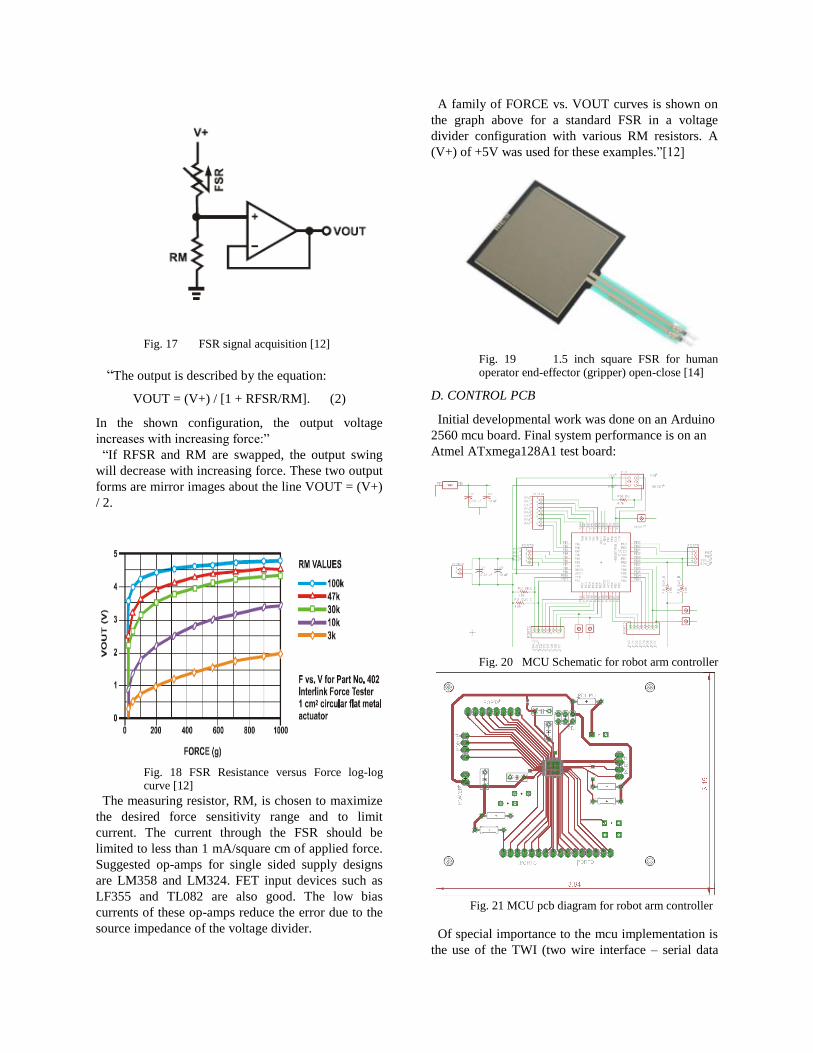
Fig. 17 FSR signal acquisition [12]
“The output is described by the equation:
VOUT = (V+) / [1 + RFSR/RM]. (2)
In the shown configuration, the output voltage
increases with increasing force:”
“If RFSR and RM are swapped, the output swing
will decrease with increasing force. These two output
forms are mirror images about the line VOUT = (V+)
/ 2.
Fig. 18 FSR Resistance versus Force log-log curve [12]
The measuring resistor, RM, is chosen to maximize
the desired force sensitivity range and to limit
current. The current through the FSR should be
limited to less than 1 mA/square cm of applied force.
Suggested op-amps for single sided supply designs
are LM358 and LM324. FET input devices such as
LF355 and TL082 are also good. The low bias
currents of these op-amps reduce the error due to the
source impedance of the voltage divider.
A family of FORCE vs. VOUT curves is shown on
the graph above for a standard FSR in a voltage
divider configuration with various RM resistors. A
(V+) of +5V was used for these examples.”[12]
Fig. 19 1.5 inch square FSR for human operator end-effector (gripper) open-close [14]
D. CONTROL PCB
Initial developmental work was done on an Arduino
2560 mcu board. Final system performance is on an
Atmel ATxmega128A1 test board:
Fig. 20 MCU Schematic for robot arm controller
Fig. 21 MCU pcb diagram for robot arm controller
Of special importance to the mcu implementation is
the use of the TWI (two wire interface – serial data

and serial clock) to connect the gyro sensor boards
into the microcontroller.
E. MOTOR ACTUATORS OF ROBOT ARM
Although dc motors driven by motor driver boards
connected to an Arduino microcontroller unit were
used to operate the plastic prototype arm, the metal
arm linkages are all driven by digital (or analog
replacement) servo motors.
Of the three types of motors available to actuate a
robot arm (neglecting hydraulic) – dc, stepper, and
Fig. 22 Three types of motors to actuate robot arm [13]
servo – servos were chosen for their superior control
qualities and the fact that the current payload
(maximum of 13 grams) does not require much
power. Standard robot shop analog and digital servos
were obtained as needed to complete the project.
F. POWER SUPPLY
There are two basic operating voltages on the
system. The sensor and microcontroller boards
operate on 3.3 Volts DC and the servos operate on
4.8V to 6.0V DC and draw about 0.2 to 1.5 amperes
of current each. A very inexpensive and effective
shared dc power bus power supply was implemented
using a discarded and still functioning personal
computer power supply unit:
Fig. 23 Shared dc power bus power supply
An STM TO-220 LD1117AV33 low drop voltage
regulator was used to step down the standby 5 volt
supply from pin #9 of the PC power supply connector
to 3.3 volts. The 5 volt supply powers the servo
motors and the 3.3 volt supply powers the sensors
and mcu.
VI. SOFTWARE
Initial software development for both the plastic arm
prototype and the metal arm was done on an Arduino
2560 micro-controller.
Final software development is done on an Atmel
ATxmega128A4U in Atmel Studio software
available free of charge for 8/16 bit AVR micro-
controller at
http://www.Atmel.com/tools/Atmelstudio.aspx
The system control flowchart is:
Fig. 24 Operating flow chart
There is a significant amount of number-crunching
involved in converting the raw data of the very
sensitive gyro sensors:
X: -4 Y: 109 Z: -9 // these are values when the gyro isn't moving
X: -5 Y: 72 Z: -17 // they average near zero
X: 22 Y: 81 Z: 5
X: 13 Y: 75 Z: 30
X: 11 Y: 75 Z: 67
X: 9 Y: 89 Z: 4
X: 27406 Y: -2091 Z: -29629 // these are values after a quick
// move of the gyro
X: 35 Y: 67 Z: 12 // next values after motion stopped
X: 26 Y: 74 Z: 50 // back near zero
Fig. 25 Sample Gyro Data (degrees/second)
II. CONCLUSION
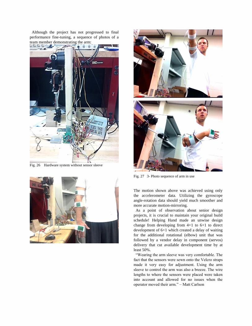
Although the project has not progressed to final
performance fine-tuning, a sequence of photos of a
team member demonstrating the arm:
Fig. 26 Hardware system without sensor sleeve
Fig. 27 3- Photo sequence of arm in use
The motion shown above was achieved using only
the accelerometer data. Utilizing the gyroscope
angle-rotation data should yield much smoother and
more accurate motion-mirroring.
As a point of observation about senior design
projects, it is crucial to maintain your original build
schedule! Helping Hand made an unwise design
change from developing from 4+1 to 6+1 to direct
development of 6+1 which created a delay of waiting
for the additional rotational (elbow) unit that was
followed by a vendor delay in component (servos)
delivery that cut available development time by at
least 50%.
“Wearing the arm sleeve was very comfortable. The
fact that the sensors were sewn onto the Velcro straps
made it very easy for adjustment. Using the arm
sleeve to control the arm was also a breeze. The wire
lengths to where the sensors were placed were taken
into account and allowed for no issues when the
operator moved their arm.” – Matt Carlson

REFERENCES
[1] Website: http://www.steelgetsreal.com/ [2] Website: http://www.syfy.com/robotcombatleague [3] Website: http://www.intuitivesurgical.com/products/davinci_surgical_system/ [4] Website: http://www.rethinkrobotics.com/ [5] Website: http://en.wikipedia.org/wiki/Haptic_technology [6] Website: http://www.isfh.org/GR-Virtual_Reality_TouchHaptics2009.pdf [7] def. exteroceptive Website: http://www.merriam-webster.com/medical/exteroceptive [8] Website: http://www.ijera.com/papers/Vol2_issue3/SQ2330983103.pdf [9] Accessed Nov. 18, 2012, Website: http://clifton.mech.northwestern.edu/~me381/project/done/Gyroscope.pdf [10] Accessed Nov. 21, 2012, Website: http://www.sensorsmag.com/files/sensor/nodes/2003/970/fig6.jpg [11] Website: http://invensense.com/mems/gyro/sixaxis.html [12] Accessed Nov 26, 2012, Website: http://www.pololu.com/file/0J383/fsr_datasheet.pdf from www.interlinklelectronics.com [13] Accessed Nov. 25, 2012, Website: http://openmoco.org/node/179 [14] Accessed Nov 26, 2012, Website: http://www.pololu.com/catalog/product/1645 [15] Accessed Mar 23, 2013, Website: http://www.lynxmotion.com/p-627-force-sensing-resistor.aspx
graduation he will be looking for employment in the
electrical engineering profession.
Email: [email protected]
URL:
www.eecs.ucf.edu/seniordesign/fa2012sp2013/g10
Currently two-thirds completed mba at UCF,
looking for employment after graduation while
finishing mba in evening courses.
Email: [email protected]
Website:
www.eecs.ucf.edu/seniordesign/fa2012sp2013/g10
Email: [email protected]
Website:
www.eecs.ucf.edu/seniordesign/fa2012sp2013/g10
Email: [email protected]
Website:
www.eecs.ucf.edu/seniordesign/fa2012sp2013/g10
Candidate for
Bachelor of
Science in Electrical
Engineering UCF
spring 2013.
Previously graduated
from UCF in BS
electrical engineering
technology.
Matthew Carlson is
currently a senior at
the University of
Central Florida and
will receive his
Bachelors of
Science in Electrical
Engineering in May
of 2013. Upon
Taylor Jones is currently a senior at the University of Central Florida and will receive his Bachelors of Science in Computer Engineering in May of 2013. He has an interest in Artificial Intelligence, game design, and robotics.
Eric Donely is currently a senior at the University of Central Florida and will receive his Bachelors of Science in Computer Engineering in May of 2013. He has an interest in computers, electronics, and robotics.