design and characterization of a 7-dof haptic interface
TRANSCRIPT

Design and Characterization of a 7-DOF Haptic Interface for aMinimally Invasive Surgery Test-bed
H. Bassan1,3, A. Talasaz1,3 and R.V. Patel1,2,3
1Department of Electrical & Computer Engineering, 2Department of Surgery, The University of Western Ontario,and
3Canadian Surgical Technologies & Advanced Robotics (CSTAR),London, Ontario, Canada.
hbassan, atalasaz, [email protected]
Abstract— In this paper, we present the design of a 7degrees-of-freedom (DOF) Haptic Interface for applications inMinimally Invasive Surgery (MIS). The design of the interfaceis based on an existing dual-panthograph Haptic Wand and iscapable of position and force reflection in three translational,three rotational DOF and grasping motion. The paper presentsthe implementation of a novel cable driven differential trans-mission to include the yaw and grasping force reflection tothe interface. The kinematic and dynamic properties of theinterface are characterized and presented. Experimental resultsdemonstrate that the device is capable of high-force reflectionwith good transparency.
Keywords: Haptic interface, force-feedback, minimallyinvasive surgery.
I. INTRODUCTION
MIS is gaining interest currently due to its benefitsto the patient and the healthcare system. As opposed toopen surgery, this approach utilizes thin instruments andan endoscope to perform surgery through tiny incisionson the patient’s body. The approach is beneficial in termsof reduced trauma and scarring, faster recovery times andshorter hospital stays. In recent years, master-slave (tele-operated) robotic systems have been introduced to assist asurgeon perform MIS procedures. While the currently usedrobotic MIS systems (such as the da Vinci from IntuitiveSurgical) do not have haptic feedback, in general, the mastermanipulator (haptic interface) of an MIS robotic systemwould be required to have force-reflection capability in allseven DOF (three translations, three rotations and grasping).
Various researchers have investigated experimental robotictest-beds for MIS. These systems utilize specialized surgicalinstruments (equipped with a force sensing capability) toprovide force feedback to the operator using a haptic in-terface. In [1], a 7-DOF haptic interface for applications inrobot-assisted MIS is presented. The device is capable offorce reflection in 4-DOF and position sensing in 7-DOF. Ahaptic interface capable of force reflection in 5-DOF for MISis presented in [2]. The design utilizes an off-the-shelf 3-DOF commercial haptic interface [3] and a custom designedgrasping and roll assembly. In [4], a 7-DOF haptic interface
This research was supported by the Ontario Centers of Excellence undergrant IC50272, and the Natural Sciences and Engineering Research Council(NSERC) of Canada under Grant CRDPJ349675-06.
based on a parallel kinematic structure is presented. Thedevice has a large number of links arranged as a dual 3-legged structure and is capable of force feedback in 7-DOF.
A few commercial haptic interfaces with 7-DOF are avail-able in the market. The Freedom 7S (MPB Technologies,Montreal, Canada) is a haptic interface with a 7-DOF forcereflection capability. The device is available with a scissorlike end-effector or an optional handle or a scalpel. However,this device is capable of very limited continuous forcereflection due to the direct-drive actuators employed in thedesign. Another commercial haptic device with 6-DOF forcereflection and 7-DOF position sensing is the PHANToM(Sensable Technologies, MA, U.S.A.). The grasping motionin this device is passive and is available either as a thumb-pad or a scissor like handle. Based on a parallel kinematicstructure for positioning and a serial-chain structure fororientation, Omega (Force Dimension, Nyon, Switzerland)is another commercial haptic interface capable of forcereflection in 7-DOF.
These haptic devices have limited applicability in MISresearch due to one or more of the following shortcomings:insufficient DOF, limited continuous force reflection, limitedworkspace or high cost. Our research group (in collaborationwith an industrial partner) has embarked on the developmentof an experimental test-bed for MIS where tool-tissue inter-action is reflected to the surgeon through a custom designedhaptic interface. In addition to robot-assisted master-slaveMIS systems, the proposed haptic device is also suitablefor application in surgical simulators (tip control similar tothe da Vinci interface). In that scenario, the trainee clinicianinteracts with a virtual anatomy on a computer using virtualsurgical tools to gain experience with the procedure. Theproposed device will also be of particular interest to otherresearchers in the field of robotics, tele-operation and MISas it provides a platform with seven DOF force reflectionwith a fairly simplistic mechanism and relatively low cost ofconstruction as compared to existing devices. The tradeoff isa slightly lower range of motion in two orientation DOF.
II. DESIGN AND DEVELOPMENT
The kinematic design of the proposed haptic interface isbased on a dual-pantograph mechanism [5] (commercially
The 2009 IEEE/RSJ International Conference onIntelligent Robots and SystemsOctober 11-15, 2009 St. Louis, USA
978-1-4244-3804-4/09/$25.00 ©2009 IEEE 4098
available as the Haptic Wand [6] from Quanser ConsultingInc., Markham, Canada). The device is available with 5-DOFposition and force-feedback capability and employs direct-drive actuators to minimize friction and maximize trans-parency. The haptic interface is controlled by linear currentamplifiers to minimize actuator heating and therefore canprovide higher force reflection for prolonged periods whileminimizing electrical interference. The kinematic structureof the original Haptic Wand utilizes dual-panthograph mech-anisms interfaced to the output handle through two Cardenjoints. Each closed-chain panthograph mechanism is actuatedthrough the use of two shoulder motors which are supportedon a single DOF waist joint resulting in a kinematic chainwith three DOF. The addition of a Carden joint at each end ofthe handle constrains the total DOF of the haptic interface tofive (three translation and two rotation: roll and pitch) with aredundant waist joint that eliminates a workspace singularityof the mechanism. The motion about the handle axis in theoriginal device is passive and un-encoded. The pantographlinkages are built of a carbon-fiber material to minimizeinertia, and two counterbalance weights are utilized to gravitybalance individual pantograph mechanism in the middle ofthe workspace. The remaining gravity compensation torque(throughout the workspace) is provided using the actuators.
A. Hardware Modifications
The original haptic wand was found to have limitedapplicability in MIS due to the lack of force reflection in theyaw direction and grasping. Thus, it was required to modifythe device to include force reflection in those DOF. Variousdesign modifications were explored and their effects on thedevice performance were examined. A common approachwould have been to redesign the output handle to include twoactuators that would provide decoupled force reflection inthe yaw and grasping. This approach however, would resultin increased handle mass and therefore higher inertia andreduced force reflection capability and transparency. Eventhough it was possible to compensate for the increased massto a certain extent by incorporating extra counterbalanceweights, the particular kinematics of the haptic wand made itdifficult to fully eliminate the effect. Increased handle masswould also have made it difficult for the user to manipulatethe device for prolonged periods, a common requirement insurgical scenarios.
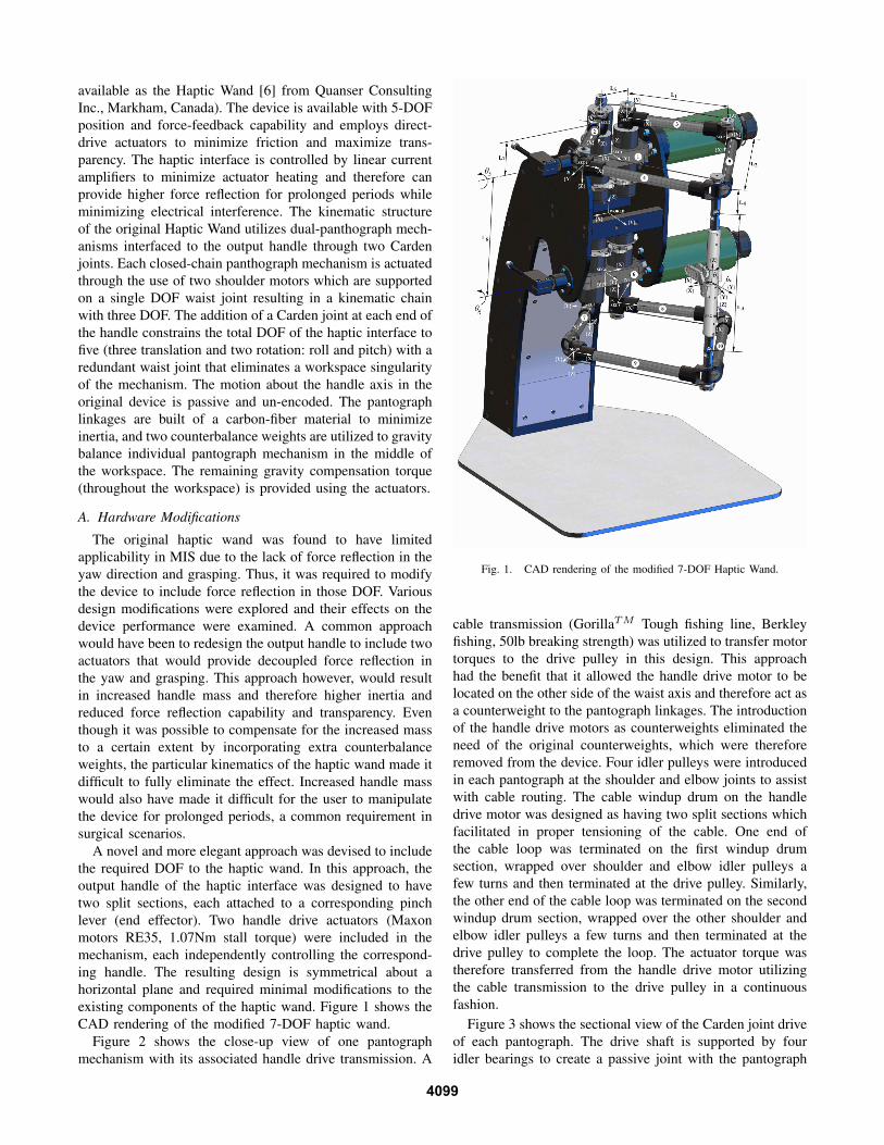
A novel and more elegant approach was devised to includethe required DOF to the haptic wand. In this approach, theoutput handle of the haptic interface was designed to havetwo split sections, each attached to a corresponding pinchlever (end effector). Two handle drive actuators (Maxonmotors RE35, 1.07Nm stall torque) were included in themechanism, each independently controlling the correspond-ing handle. The resulting design is symmetrical about ahorizontal plane and required minimal modifications to theexisting components of the haptic wand. Figure 1 shows theCAD rendering of the modified 7-DOF haptic wand.
Figure 2 shows the close-up view of one pantographmechanism with its associated handle drive transmission. A
Fig. 1. CAD rendering of the modified 7-DOF Haptic Wand.
cable transmission (GorillaTM Tough fishing line, Berkleyfishing, 50lb breaking strength) was utilized to transfer motortorques to the drive pulley in this design. This approachhad the benefit that it allowed the handle drive motor to belocated on the other side of the waist axis and therefore act asa counterweight to the pantograph linkages. The introductionof the handle drive motors as counterweights eliminated theneed of the original counterweights, which were thereforeremoved from the device. Four idler pulleys were introducedin each pantograph at the shoulder and elbow joints to assistwith cable routing. The cable windup drum on the handledrive motor was designed as having two split sections whichfacilitated in proper tensioning of the cable. One end ofthe cable loop was terminated on the first windup drumsection, wrapped over shoulder and elbow idler pulleys afew turns and then terminated at the drive pulley. Similarly,the other end of the cable loop was terminated on the secondwindup drum section, wrapped over the other shoulder andelbow idler pulleys a few turns and then terminated at thedrive pulley to complete the loop. The actuator torque wastherefore transferred from the handle drive motor utilizingthe cable transmission to the drive pulley in a continuousfashion.
Figure 3 shows the sectional view of the Carden joint driveof each pantograph. The drive shaft is supported by fouridler bearings to create a passive joint with the pantograph
4099

Fig. 2. CAD rendering of the upper handle drive.
mechanism and therefore can be independently rotated withrespect to the pantograph. At each end, the drive shaft isfirmly attached to the drive pulley and the input link of theCarden joint, respectively. The output link of the Cardenjoint is firmly attached to the handle and therefore actuatortorque is transferred from the drive pulley through the driveshaft, through the carden joint to the handle and to thecorresponding pinch lever.
Fig. 3. Section view of the carden joint drive.
The upper and lower handles are coupled to each otherthrough a passive joint (with its axis aligned with thelongitudinal axes of the handles). In a typical setting, theuser would hold the pinch levers utilizing the thumb andthe index finger and could utilize the remaining fingers andpalm to hold onto one of the handles for a better support.Velcro straps are attached to the pinch levers to maintain afirm contact with user’s fingers at all times. The pinch leverswere designed to be removable and can be easily replaced
with other types of end-effectors (such as scissor handlesetc), if required. The handles, pinch levers and idler pulleyswere all manufactured using a rapid prototyping 3D printer(light weight ABS plastic material). Figure 4 shows the 7-DOF haptic wand.
The upper and lower pinch levers are individually actuatedby the corresponding motors, however, as the user grasps thelevers using the thumb and the index finger, a differentialmechanism is created between the two. The yaw angle in thetool frame, denoted as θ7 (Figure 1), is defined in the right-handed sense about the haptic wand handle and the graspangle, denoted as θ8, is the angle between the upper andlower pinch levers. The motion in the yaw and the graspingdirections can be measured as follows:
θ7 =θM1 − θM2
2(1)
andθ8 = −(θM1 + θM2) (2)
where θM1 (Figure 2) and θM2 are the right-handed angleof the upper and lower pinch lever actuators, respectively.The output torque in the yaw and grasping directions in termsof upper and lower actuator torques are then given by:
τ7 =τM1 − τM2
2(3)
andτ8 =
τM1 + τM2
2(4)
Fig. 4. 7-DOF Haptic Wand.
B. Forward Kinematics
The forward kinematics of the manipulator describe theend effector position and orientation with reference to aworld frame as a function of its joint angles. For ease ofkinematic and dynamic analyses, Figure 1 indicates the world
4100

frame and segments 1 through 11 with their respective localcoordinate systems (SEG1−11). These segments include thetop triple motor assembly, top left drive arm, top right drivearm, top left passive arm, top right passive arm, bottom triplemotor assembly, bottom left drive arm, bottom right drivearm, bottom left passive arm and bottom right passive arm,labelled as 1 through 11, respectively. The haptic wand endeffector is located in the middle of the handle and the toolcoordinate system is parallel to the global coordinate systemat the home position. The parameters L1, . . . , L7 are definedas the distance between various frames. To solve the forwardkinematics of the haptic wand, the problem is broken downinto two smaller problems, i.e., forward kinematics for theupper pantograph and the lower pantograph, with end points(rEU and rEL) defined for these subsystems (see Figure 2).
Now referring to Figure 1, for the upper pantograph:
rSEG1 =
00L62
(5)
rSEG2 =
L52
−s5L7L62 + c5L7
(6)
rSEG3 =
−L52
−s5L7L62 + c5L7
(7)
rSEG4 =
L52 + c1L1
−s5L7 + c5s1L1L62 + c5L7 + s5s1L1
(8)
rSEG5 =
−L52 + c2L1
−s5L7 + c5s2L1L62 + c5L7 + s5s2L1
(9)
where, for i = 1, .., 5, rSEGi is the origin of the frameattached to the SEGi with respect to the world coordinatesystem and ci and si stand for cos(θi) and sin(θi), respec-tively.
Referring to Figure 2, the position of the upper end pointis computed as:
αU = arctans1L1 − s2L1
L5 + c1L1 − c2L1(10)
and
βU = arccoshU
2L2(11)
wherehU = ‖rSEG4 − rSEG5‖ (12)
Now, defineψU = π − (βU − αU ) (13)
andγU = αU + βU (14)
then, we get
rEU = rSEG4 +Rx(θ5)Rz(ψU )
L2
0−L4
(15)
where, Rj(κ) represents a rotation matrix about an axis jthrough an angle κ. Similarly, for the lower end point weget
rEL = rSEG9 +Rx(θ6)Rz(ψL)
L2
0L4
(16)
The haptic wand end effector is located in the middle ofa straight line between the upper and lower end points (rEU
and rEL). Therefore, we have
rEE = rEL +rEU − rEL
2(17)
where rEE is the position of the haptic wand end effector.To calculate the orientation of the end effector, the roll,
pitch and yaw angles are defined in the right-hand senseabout the world X, Y and Z axes, respectively. Let us definea unit vector of the handle in the global frame as
uh =rEU − rEL
‖rEU − rEL‖(18)
and
G = Rz(−ψL)Rx(−θ6)[0 0 uh
]Rz(−θ7) (19)
by defining
µ = arctanG(1, 3)G(3, 3)
(20)
andυ = − arcsinG(2, 3) (21)
we can then compute
REE = Rx(θ6)Rz(ψL)Ry(µ)Rx(υ)Rz(θ7) (22)
from 22, we can derive the Euler angles (about the worldframe axes) using the following
oroll = arctanREE(3, 2)REE(3, 3)
(23)
opitch = arctan−REE(3, 1)√1 +REE(3, 1)
(24)
oyaw = arctanREE(2, 1)REE(1, 1)
(25)
C. Dynamics
The dynamic equations of the haptic wand are derivedusing the Lagrangian formulation. The location of the centerof mass for segment i in the local frame, rl
cmi, can beexpressed in world coordinates, rw
cmi, as
rwcmi = rw
oi +Rx(φi)Rz(ϕi) rlcmi (26)
where rwoi is the position of the origin of the local frame for
segment i and φi is equal to θ5 for the upper pantograph,
4101

θ6 for the lower pantograph and 0 for the handle. we alsohave
ϕ =[0 θ1 θ2 ψU γU 0 θ3 θ4 ψL γL χ
]Since the origin of the tool frame is coincident with thecenter of mass of the handle, we have rl
cm11 = 0. For i =1, 6, rl
cmi =[0 −lcmi 0
]Tand for the other segments
rlcmi =
[lcmi 0 0
]T.
The rotational velocity, Ωi for i = 1, . . . , 11, in localframes is given by
Ω1 =
ω5
00
Ω6 =
ω6
00
Ω11 =
00ω11
(27)
Ω2 =
c1ω5
−s1ω5
ω1
Ω3 =
c2ω5
−s2ω5
ω2
(28)
Ω7 =
c3ω6
−s3ω6
ω3
Ω8 =
c4ω6
−s4ω6
ω4
(29)
Ω4 = Rz(−ψU ) Ω1 +
00ψU
(30)
Ω5 = Rz(−γU ) Ω1 +
00˙γU
(31)
Ω9 = Rz(−ψL) Ω6 +
00ψL
(32)
Ω10 = Rz(−γL) Ω6 +
00γL
(33)
The translational velocity is also defined for the center ofmass vector and is calculated as
vcmi = rcmi for i = 1, · · · , 11
The kinetic energy for each segment is given by
Ki =12
(vTcmiMi vcmi + ΩT
i Ii Ωi) (34)
where Mi = mi I3×3 and Ii are respectively the translationaland rotational inertia matrices for i = 1, .., 11. The potentialenergy for the segment i is defined as
Vi = mi g rzcmi (35)
where rzcmi is the third element of the vector rcmi (Z
direction). Then the lagrangian for the haptic wand is givenby
L =11∑
i=1
Ki −11∑
i=1
Vi (36)
and, the dynamic equations are calculated from
d
dt
∂L
∂θi
− ∂L
∂θi= τi, i = 1, .., 7. (37)
TABLE IHAPTIC WAND PARAMETERS
i mi(kg) lcmi(m) Li(m)1 1.1000 0.011 0.14432 0.0601 0.042 0.19613 0.0601 0.042 0.21144 0.0543 0.090 0.03595 0.0581 0.090 0.04456 1.1000 0.011 0.17787 0.0601 0.042 0.05268 0.0601 0.042 −9 0.0543 0.090 −
10 0.0581 0.090 −11 0.0637 − −
TABLE IIHAPTIC WAND WORKSPACE
Translation (mm) 480W x 450H x 250DRotation (deg) ±85 (roll)
±65 (pitch)±160 (yaw)30 (grasp)
D. Haptic Wand Parameters
The pantograph links of the haptic interface are made upof hollow carbon fiber tubing and therefore have negligiblemass and inertia. For simplicity of the dynamic model,these parameters are excluded from the calculations and onlythe inertia of the motor assemblies in the following form,expressed in local frames, are utilized.Iixx 0 0
0 Iiyy 00 0 Iizz
i = 1, 6. (38)
At the same time, the rotational velocity for the upper andlower motor assemblies is only about the X-axis and as aresult, only I1xx, I6xx are involved in the kinetic energycalculation. The measured values for these parameters (inkg m2) are
I1xx = 0.00163 I6xx = 0.00163
The other parameters for the 7-DOF haptic wand are sum-marized in Table I and the workspace is given in Table II.
III. EXPERIMENTS
To evaluate the closed-loop performance and measure thetransparency of force reflection, the kinematic and dynamicmodels developed in sections II-B and II-C were utilized tocreate a virtual wall simulation for the haptic interface [7].An impedance control algorithm as shown in Figure 5 wasimplemented for the experiments reported in this paper.
The impedance controller was designed so as to match thedynamics of the haptic wand with those of the virtual wall.The wall was assumed to be linear and decoupled in each co-ordinate and therefore, a simplified decoupled controller wasdesigned for each DOF. The decoupled controllers requirevelocity feedback in world coordinates (linear and angular)that was derived from the joint velocities of the motors andthe Jacobian of the haptic wand. The joint velocities were
4102

Fig. 5. Control block diagram for 7-DOF haptic wand including virtualenvironment.
estimated from the encoder measurements using a velocityobserver. The interaction force between the haptic wand andthe operator’s hand was measured by a force observer thatwas designed based on the obtained dynamics of the hapticwand [8]. In order to precisely transfer the simulated forcesfrom the virtual wall to the operator, the gravity terms wereextracted from the dynamics equations and fed forward tothe controller.
The virtual wall [9] was modeled as a spring-dampersystem and using this model, the reaction wall force canbe computed as
Fw = −ζ[Kw(X −Xw) + γBwX] (39)
where Kw and Bw are the spring and damper constants,respectively and ζ and γ are defined as
ζ =
1 X > Xw
0 X ≤ Xwγ =
1 X > 00 X ≤ 0
(40)
The parameter ζ guarantees that no force is exerted on theend effector unless the handle penetrates the virtual wall.Simultaneously, selecting γ as given in (40) ensures that noextra force is applied to the operator’s hand when the handleis being removed from the wall.
Figures 6 and 7 show the tracking response of the hapticinterface for three translational and three rotational DOF,respectively. The handle was kept in a fixed position duringthe experiment. In order to evaluate the transparency of forcereflection, the following values for environment stiffnesswere selected:
Kw =
500 t ≤ 301000 t > 50 (41)
It can be seen from Figures 6 and 7 that the interactionforce between the haptic wand and the operator’s handcorrespond accurately to the force reflected from the virtualwall.
IV. CONCLUSION
In this paper, we have presented the design, developmentand modeling of a seven-DOF haptic interface for minimallyinvasive surgery. An existing 5-DOF haptic interface was
Fig. 6. Tracking response for translational DOF.
Fig. 7. Tracking response for rotational DOF.
modified to include force-feedback in the yaw and graspingdirections through the use of a highly-backdrivable cable-driven differential transmission. The kinematic and dynamicanalyses of the modified interface was presented. Futurework will involve integration of the haptic interface into amaster-slave robotic test-bed to evaluate haptic-based tele-manipulation.
V. ACKNOWLEDGEMENTS
The authors would like to thank Jacob Apkarian, RyanLeslie and Paul Karam at Quanser Consulting Inc., for helpwith the QuaRC software and the kinematics and dynamicsof the 5-DOF Haptic Wand.
REFERENCES
[1] G. Tholey and J. P. Desai, “A general-purpose 7 DOF haptic devive:Applications toward robot-assisted surgery,” IEEE/ASME Transactionson Mechatronics, vol. 12, pp. 662–669, Dec. 2007.
[2] M. Tavakoli, R. Patel, M. Moallem, and A. Aziminejad, Haptics-BasedSystems for Robot-Assisted Surgery and Telesurgery: Design, Control,and Experimentation. World Scientific Publishers in the series - NewFrontiers in Robotics, 2008.
[3] T. H. Massie and J. K. Salisbury, “Force reflecting haptic interface,” inU.S. patent 5,625,576, 1999.
[4] K. Kim, W. K. Chung, and Y. Youm, “Design and analysis of a new 7-DOF parallel type haptic device : PATHOS-II,” in IEEE/RSJ Conferenceon Intelligent Robots and Systems, pp. 2241–2246, 2003.
[5] L. J. Stocco, S. E. Salcudean, and F. Sassani, “Optimal kinematic designof a haptic pen,” IEEE/ASME Transactions on Mechatronics, vol. 6,pp. 210–220, Sept. 2001.
[6] http://www.quanser.com.[7] M. R. Sirouspour, S. P. DiMaio, S. E. Salcudean, P. Abolmaesumi, and
C. Jones, “Haptic interface control-design issues and experiments witha planar device,” in IEEE International Conference on Robotics andAutomation, pp. 789–794, 2000.
[8] A. C. Smith, F. Mobasser, and K. Hashtrudi-Zaad, “Neural-network-based contact force observers for haptic applications,” IEEE Transac-tions on Robotics, vol. 22, pp. 1163–1175, Dec. 2006.
[9] J. Yoon and J. Ryu, “Control and evaluation of a new 6-dof haptic deviceusing a parallel mechanism,” in IEEE/RSJ Conference on IntelligentRobots and Systems, pp. 1125–1130, 2000.
4103